EP2319763A1 - Protection for elements made from composite material - Google Patents
Protection for elements made from composite material Download PDFInfo
- Publication number
- EP2319763A1 EP2319763A1 EP09784136A EP09784136A EP2319763A1 EP 2319763 A1 EP2319763 A1 EP 2319763A1 EP 09784136 A EP09784136 A EP 09784136A EP 09784136 A EP09784136 A EP 09784136A EP 2319763 A1 EP2319763 A1 EP 2319763A1
- Authority
- EP
- European Patent Office
- Prior art keywords
- composite material
- resin
- edges
- corners
- protection
- Prior art date
- Legal status (The legal status is an assumption and is not a legal conclusion. Google has not performed a legal analysis and makes no representation as to the accuracy of the status listed.)
- Granted
Links
- 239000002131 composite material Substances 0.000 title claims abstract description 44
- 239000011347 resin Substances 0.000 claims abstract description 40
- 229920005989 resin Polymers 0.000 claims abstract description 40
- 238000004519 manufacturing process Methods 0.000 claims abstract description 24
- 238000000034 method Methods 0.000 claims abstract description 18
- 239000002245 particle Substances 0.000 claims abstract description 5
- 238000009825 accumulation Methods 0.000 claims abstract description 4
- 238000010292 electrical insulation Methods 0.000 claims abstract description 3
- 238000009413 insulation Methods 0.000 claims description 8
- 239000000835 fiber Substances 0.000 claims description 6
- OKTJSMMVPCPJKN-UHFFFAOYSA-N Carbon Chemical compound [C] OKTJSMMVPCPJKN-UHFFFAOYSA-N 0.000 claims description 4
- 229910052799 carbon Inorganic materials 0.000 claims description 4
- 239000003822 epoxy resin Substances 0.000 claims description 3
- 229920000647 polyepoxide Polymers 0.000 claims description 3
- 239000007789 gas Substances 0.000 claims description 2
- 239000007788 liquid Substances 0.000 claims description 2
- 239000007787 solid Substances 0.000 claims description 2
- 239000010410 layer Substances 0.000 description 10
- 239000002828 fuel tank Substances 0.000 description 5
- 239000000463 material Substances 0.000 description 4
- 230000004888 barrier function Effects 0.000 description 3
- 239000003989 dielectric material Substances 0.000 description 3
- 239000003365 glass fiber Substances 0.000 description 3
- 239000011229 interlayer Substances 0.000 description 3
- 239000004848 polyfunctional curative Substances 0.000 description 3
- 239000003795 chemical substances by application Substances 0.000 description 2
- 239000000615 nonconductor Substances 0.000 description 2
- 239000000565 sealant Substances 0.000 description 2
- 239000012141 concentrate Substances 0.000 description 1
- 239000004020 conductor Substances 0.000 description 1
- 230000006866 deterioration Effects 0.000 description 1
- 238000005516 engineering process Methods 0.000 description 1
- 238000004880 explosion Methods 0.000 description 1
- 239000000446 fuel Substances 0.000 description 1
- 239000011810 insulating material Substances 0.000 description 1
- 239000012212 insulator Substances 0.000 description 1
- 230000010354 integration Effects 0.000 description 1
- 238000005259 measurement Methods 0.000 description 1
- 239000007769 metal material Substances 0.000 description 1
- 238000012986 modification Methods 0.000 description 1
- 230000004048 modification Effects 0.000 description 1
- 238000007789 sealing Methods 0.000 description 1
- 239000003381 stabilizer Substances 0.000 description 1
Images

Classifications
-
- B—PERFORMING OPERATIONS; TRANSPORTING
- B64—AIRCRAFT; AVIATION; COSMONAUTICS
- B64D—EQUIPMENT FOR FITTING IN OR TO AIRCRAFT; FLIGHT SUITS; PARACHUTES; ARRANGEMENT OR MOUNTING OF POWER PLANTS OR PROPULSION TRANSMISSIONS IN AIRCRAFT
- B64D45/00—Aircraft indicators or protectors not otherwise provided for
- B64D45/02—Lightning protectors; Static dischargers
-
- B—PERFORMING OPERATIONS; TRANSPORTING
- B29—WORKING OF PLASTICS; WORKING OF SUBSTANCES IN A PLASTIC STATE IN GENERAL
- B29C—SHAPING OR JOINING OF PLASTICS; SHAPING OF MATERIAL IN A PLASTIC STATE, NOT OTHERWISE PROVIDED FOR; AFTER-TREATMENT OF THE SHAPED PRODUCTS, e.g. REPAIRING
- B29C70/00—Shaping composites, i.e. plastics material comprising reinforcements, fillers or preformed parts, e.g. inserts
- B29C70/88—Shaping composites, i.e. plastics material comprising reinforcements, fillers or preformed parts, e.g. inserts characterised primarily by possessing specific properties, e.g. electrically conductive or locally reinforced
-
- B—PERFORMING OPERATIONS; TRANSPORTING
- B29—WORKING OF PLASTICS; WORKING OF SUBSTANCES IN A PLASTIC STATE IN GENERAL
- B29K—INDEXING SCHEME ASSOCIATED WITH SUBCLASSES B29B, B29C OR B29D, RELATING TO MOULDING MATERIALS OR TO MATERIALS FOR MOULDS, REINFORCEMENTS, FILLERS OR PREFORMED PARTS, e.g. INSERTS
- B29K2063/00—Use of EP, i.e. epoxy resins or derivatives thereof, as moulding material
-
- B—PERFORMING OPERATIONS; TRANSPORTING
- B29—WORKING OF PLASTICS; WORKING OF SUBSTANCES IN A PLASTIC STATE IN GENERAL
- B29K—INDEXING SCHEME ASSOCIATED WITH SUBCLASSES B29B, B29C OR B29D, RELATING TO MOULDING MATERIALS OR TO MATERIALS FOR MOULDS, REINFORCEMENTS, FILLERS OR PREFORMED PARTS, e.g. INSERTS
- B29K2707/00—Use of elements other than metals for preformed parts, e.g. for inserts
- B29K2707/04—Carbon
-
- Y—GENERAL TAGGING OF NEW TECHNOLOGICAL DEVELOPMENTS; GENERAL TAGGING OF CROSS-SECTIONAL TECHNOLOGIES SPANNING OVER SEVERAL SECTIONS OF THE IPC; TECHNICAL SUBJECTS COVERED BY FORMER USPC CROSS-REFERENCE ART COLLECTIONS [XRACs] AND DIGESTS
- Y10—TECHNICAL SUBJECTS COVERED BY FORMER USPC
- Y10T—TECHNICAL SUBJECTS COVERED BY FORMER US CLASSIFICATION
- Y10T428/00—Stock material or miscellaneous articles
- Y10T428/24—Structurally defined web or sheet [e.g., overall dimension, etc.]
- Y10T428/24777—Edge feature
Definitions
- the present invention relates to elements made of composite material, particularly aircraft parts, protected against electric discharges, as well as to a method of manufacture of said elements.
- the present invention aims to solve the problems that have just been outlined.
- the present invention relates to elements, particularly of aircraft, made of composite material and protected against electric discharges to which they are potentially exposed, for example arising from a lightning strike.
- the invention is especially relevant to structures, in particular of aircraft, which, owing to their function of containing flammable liquids, gases or solids, must be properly protected against sources of ignition that might produce a risk of explosion.
- the present invention applies in particular to the aeronautical context, in which manufacture in composite materials is now very common and moreover in some cases said components fulfil the function of fuel tanks, as for example in the case of the wings and the horizontal stabilizers (trim tanks).
- the invention relates to elements made of composite material protected against electric discharges, said elements comprising a layer of non-conductive, insulating resin arranged on the edges that require protection, in such a way that said layer of resin is produced in the manufacturing process proper of the element in composite material, in one go and without the need for subsequent operations for specific protection of the edges.
- the invention does not present any major technical limitations in its application, since the aim is to obtain protection on the edges of the elements of composite material at the same time and in the same process of manufacture of said element.
- the invention assumes particular relevance in connection with the capacity for applying the resin on especially complex geometries, because it does not require an additional, special process for application of the insulating barrier, as application of the non-conductive resin is already integrated in the manufacturing process proper for the element.
- the invention relates to a process for the manufacture of elements as described previously, particularly aircraft parts, made of composite material and potentially exposed to electric discharges. This process comprises the following stages:
- the invention relates to an element manufactured in composite material and protected against electric discharges at its points of complex geometry, such as various edges and corners, where said element is manufactured in carbon-fibre composite and is mainly an element for aircraft.
- the edges of aircraft parts potentially exposed to electric discharges must be protected with a dielectric material (electrical insulator) in order to prevent electric arcs or incandescent particles, which damage the material in unpredictable ways, causing a deterioration of its mechanical properties, or which constitute sources of ignition if located in flammable atmospheres (as in the case of fuel tanks made of carbon fibre).
- the invention although applicable in a wider context, has been developed in an aeronautical setting.
- the probability of a commercial aircraft suffering a lightning strike (electric discharge) is high: it is calculated that an aircraft suffers on average almost two lightning strikes per year. Therefore it is necessary to take adequate measures to ensure firstly the safety of the passengers and, secondly, that the lightning strike has the least possible effect on the operation of the aircraft.
- the solution developed by the invention meets the requirement of insulating the edges electrically, by means of a robust solution of high integrity, from the electrical standpoint, as well as being simple to apply, through integration in the manufacturing process.
- the epoxy resin that is a component of the composite material that concentrates naturally on the edges of the parts or elements produced in a controlled manner on the basis of appropriate dimensions of the mould for the part or element and the precise amount of resin
- the element 1 of composite material is obtained by applying a cycle of temperature and pressure on the basis of a mould 2 designed in such a way that, once the geometry of the element 1 in question is known, the mould 2 is designed so that it comprises spaces 6 intended to accomodate resin from the manufacturing process of the element 1, and said resin will form the dielectric protection of the edges of the element 1.
- the mould 2 includes spaces 6 on designated free edges on which dielectric (insulating) protection of the element 1 is required, thus permitting the accumulation of resin in said spaces 6 during the process of manufacture of said element 1.
- the resin accumulates forming a layer 3 that is disposed around the free edge of the element 1, thus endowing this edged surface with dielectric protection (electrical insulation) that prevents possible discharges and expulsion of hot particles in case of a lightning strike or equivalent severe electric discharge on said element 1.
- the layer 3 of resin will need to have a thickness between 4 and 5 mm, so as to ensure a substantial dielectric or insulation capacity on the edges of said element 1.
- Thickness resistivity in depth (Z axis) (Ohms) Volume resistivity (Ohms.cm)
- Resin 8552/IM7 (without resin or hardener interlayers) 0.50
- Resin M21/IMA (with resin or hardener interlayers) 5.6-7.7 287-397
- Resin M21E/IMA (with resin or hardener interlayers) 9.1 469
- Fig. 2 shows a schematic representation of the particular application of the invention for stringers 4 in composite material for aircraft, which include coverings 5 of composite material, in particular of carbon fibre.
- the invention relates to a process for the manufacture of elements 1 as described previously, particularly aircraft parts, made of composite material and potentially exposed to electric discharges. This process comprises the following stages:
Landscapes
- Engineering & Computer Science (AREA)
- Chemical & Material Sciences (AREA)
- Composite Materials (AREA)
- Mechanical Engineering (AREA)
- Aviation & Aerospace Engineering (AREA)
- Casting Or Compression Moulding Of Plastics Or The Like (AREA)
- Moulding By Coating Moulds (AREA)
- Laminated Bodies (AREA)
- Reinforced Plastic Materials (AREA)
Abstract
Description
- The present invention relates to elements made of composite material, particularly aircraft parts, protected against electric discharges, as well as to a method of manufacture of said elements.
- Technologies based on the use of composite materials are now being used increasingly in industry for the production of components. Thus, there has been a particularly large increase in the proportion of composites being employed in the field of aeronautics, constituting the so-called aeronautical structures. However, this trend towards materials that are poor conductors relative to the traditional components in metallic materials requires exhaustive protection of them against external agents such as electric discharges, mainly, in the case of elements that make up aircraft structures, for the discharges produced by a lightning strike. This protection is of the utmost importance when the component or element in question contains fuel vapours or potentially flammable atmospheres, as is the case for the fuel tanks or the wings of an aircraft, when these last-mentioned components also perform the function of fuel tanks. In these cases, all the internal zones must be protected to prevent discharges of incandescent particles or electric arcs that could become sources of ignition.
- Despite current advances in protection against lightning and other external agents that involve an electric discharge, especially in the field of aeronautics, there are great difficulties in applying the proposed theoretical elements of protection at the manufacturing stage. This problem is especially pronounced in the area of the protection of edges of complex geometry in aircraft, for which a dielectric material (electrical insulator) is required along the entire length of the edge, in order to prevent arcs and discharges. However, it proves to be highly complex, from a practical standpoint, to apply insulating products on these edges, performing the function both of physical barrier and of electrical barrier, in a robust and integral manner, and throughout the working life of the component in question.
- Means for protecting the edges of components made of composite material are known in the prior art. However, these means are expensive, as they are mainly carried out manually, and moreover said manual application is very difficult. Thus, sealing elements are known at present, which are positioned on the edges of components in composite material, but they present problems of durability with the passage of time, as they lose their integrity. The application of films or layers of insulating materials on the edges of composite components is also known (said application being carried out following manufacture of the component in composite material), these films or layers usually being constituted of glass fibre or some other layer of dielectric material. This solution has the drawback that it requires a laborious and expensive additional process, and it does not adapt correctly to surfaces of difficult geometry, for example those that have curvatures.
- The present invention aims to solve the problems that have just been outlined.
- Thus, according to a first aspect, the present invention relates to elements, particularly of aircraft, made of composite material and protected against electric discharges to which they are potentially exposed, for example arising from a lightning strike. The invention is especially relevant to structures, in particular of aircraft, which, owing to their function of containing flammable liquids, gases or solids, must be properly protected against sources of ignition that might produce a risk of explosion.
- As already mentioned, the present invention applies in particular to the aeronautical context, in which manufacture in composite materials is now very common and moreover in some cases said components fulfil the function of fuel tanks, as for example in the case of the wings and the horizontal stabilizers (trim tanks).
- Thus, the invention relates to elements made of composite material protected against electric discharges, said elements comprising a layer of non-conductive, insulating resin arranged on the edges that require protection, in such a way that said layer of resin is produced in the manufacturing process proper of the element in composite material, in one go and without the need for subsequent operations for specific protection of the edges. Thus, the invention does not present any major technical limitations in its application, since the aim is to obtain protection on the edges of the elements of composite material at the same time and in the same process of manufacture of said element.
- The invention assumes particular relevance in connection with the capacity for applying the resin on especially complex geometries, because it does not require an additional, special process for application of the insulating barrier, as application of the non-conductive resin is already integrated in the manufacturing process proper for the element.
- According to a second aspect, the invention relates to a process for the manufacture of elements as described previously, particularly aircraft parts, made of composite material and potentially exposed to electric discharges. This process comprises the following stages:
- a) Design of the element or component: the geometry of said element or component is defined without taking into account the thickness of the protection on the edges that would be difficult to apply.
- b) Identification of the edges of the element or component on which protection is required based on insulation of said edges. Normally, for the invention, those edges are considered on which the application of common dielectric protection, such as sealants, glass fibre, etc. is complex, of difficult access or requires expensive manual work.
- c) Definition and design of the mould in which the aircraft element or component is produced, taking into account the distances for defining the spaces identified in the edges and that require dielectric protection. A layer of non-conductive, insulating resin will be disposed in these spaces disposed on the edges, during the manufacturing process proper of the element or component in composite material.
- d) Facing of the edges to level the excesses of resin to the required thickness, so as to ensure the necessary dielectric strength on said edges.
- Other characteristics and advantages of the present invention will become clear from the detailed description that follows, of an application illustrating its object, referring to the accompanying drawings.
-
-
Fig. 1 shows a schematic plan view of the element made of composite material protected against electric discharges on its edges (localized accumulation of resin), according to the present invention. -
Fig. 2 shows a schematic elevation of the element made of composite material protected against electric discharges according to the present invention, in its concrete application of stringers of aircraft. -
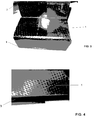
Fig. 3 shows a view of an element of composite material with extra resin manufactured in such a way that resin has accumulated, before the stage of facing of edges, according to the method of manufacture of the present invention. -
Fig. 4 shows a detail view of the edge of an element of composite material manufactured by the method of manufacture of the present invention, before the stage of facing of edges. - According to a first aspect, the invention relates to an element manufactured in composite material and protected against electric discharges at its points of complex geometry, such as various edges and corners, where said element is manufactured in carbon-fibre composite and is mainly an element for aircraft. Often, the edges of aircraft parts potentially exposed to electric discharges must be protected with a dielectric material (electrical insulator) in order to prevent electric arcs or incandescent particles, which damage the material in unpredictable ways, causing a deterioration of its mechanical properties, or which constitute sources of ignition if located in flammable atmospheres (as in the case of fuel tanks made of carbon fibre).
- The invention, although applicable in a wider context, has been developed in an aeronautical setting. The probability of a commercial aircraft suffering a lightning strike (electric discharge) is high: it is calculated that an aircraft suffers on average almost two lightning strikes per year. Therefore it is necessary to take adequate measures to ensure firstly the safety of the passengers and, secondly, that the lightning strike has the least possible effect on the operation of the aircraft.
- Thus, faced with the difficulty of covering all the internal edges that could potentially cause electric discharges in an aircraft due to a lightning strike, the solution developed by the invention meets the requirement of insulating the edges electrically, by means of a robust solution of high integrity, from the electrical standpoint, as well as being simple to apply, through integration in the manufacturing process.
- In the process of manufacture of composites (fibre plus resin co-cured in a thermal vacuum process) there is build-up of surplus material resulting from the flow of resin towards the ends of the part or element. The idea developed by the present invention is to utilize said surplus material of high insulating capacity (with very high dielectric strength constant) to fulfil the requirement of protection of edges against electric discharges.
- Thus, using the epoxy resin that is a component of the composite material that concentrates naturally on the edges of the parts or elements produced in a controlled manner (on the basis of appropriate dimensions of the mould for the part or element and the precise amount of resin) it is possible to obtain, in one go and without the need for subsequent operations, a system for the specific protection of the edges against electric discharges.
- Thus, the element 1 of composite material, said composite material being for example carbon fibre with epoxy resin, is obtained by applying a cycle of temperature and pressure on the basis of a
mould 2 designed in such a way that, once the geometry of the element 1 in question is known, themould 2 is designed so that it comprises spaces 6 intended to accomodate resin from the manufacturing process of the element 1, and said resin will form the dielectric protection of the edges of the element 1. Thus, themould 2 includes spaces 6 on designated free edges on which dielectric (insulating) protection of the element 1 is required, thus permitting the accumulation of resin in said spaces 6 during the process of manufacture of said element 1. The resin accumulates forming alayer 3 that is disposed around the free edge of the element 1, thus endowing this edged surface with dielectric protection (electrical insulation) that prevents possible discharges and expulsion of hot particles in case of a lightning strike or equivalent severe electric discharge on said element 1. - The
layer 3 of resin will need to have a thickness between 4 and 5 mm, so as to ensure a substantial dielectric or insulation capacity on the edges of said element 1. - All the resins employed for composites that are currently used for making aircraft structures are insulators, although their insulation capacity (capacity for withstanding potential differences) is greater in the latest generation of resins. A table is given below, showing the results of experimental measurements relating to resins very commonly used in the manufacture of parts in composite material for aeronautical structures. Thus, based on the values obtained, shown in this table, it can be stated that all the resins tested shown in this table are insulating from an electrical standpoint for the application of protection of edges, for example in aircraft fuel tanks. However, the greater the insulation capacity of the resin, the smaller is the thickness required in the
layer 3 of resin for withstanding potential differences in the element 1.Thickness resistivity in depth (Z axis) (Ohms) Volume resistivity (Ohms.cm) Resin 8552/IM7 (without resin or hardener interlayers) 0.50 25.8 Resin M21/IMA (with resin or hardener interlayers) 5.6-7.7 287-397 Resin M21E/IMA (with resin or hardener interlayers) 9.1 469 -
Fig. 2 shows a schematic representation of the particular application of the invention forstringers 4 in composite material for aircraft, which includecoverings 5 of composite material, in particular of carbon fibre. - According to a second aspect, the invention relates to a process for the manufacture of elements 1 as described previously, particularly aircraft parts, made of composite material and potentially exposed to electric discharges. This process comprises the following stages:
- a) Design of the element 1: the geometry of said element 1 is defined without taking into account the thickness of the protection on the edges for which application is difficult.
- b) Identification of the edges of the element 1 on which protection is required, based on insulation of said edges. Normally, for the invention, consideration is given to those edges on which the application of common dielectric protection, such as sealants, glass fibre, etc. is complex, of difficult access or requires expensive manual work.
- c) Definition and design of the
mould 2 in which the aircraft element 1 is produced, taking into account the distances for defining the spaces identified in the edges that require dielectric protection. Alayer 3 of non-conductive, insulating resin will be disposed in these spaces disposed on the edges, during the manufacturing process proper of the element or component in composite material. - d) Facing of the edges to level the excesses of resin to the required thickness, so as to ensure the necessary dielectric strength on said edges.
- Modifications that are included within the scope defined by the following claims can be introduced in the preferred embodiment that we have just described.
Claims (8)
- Element (1) of composite material protected at its points of complex geometry, such as various edges and corners, against electric discharges to which it is potentially exposed, characterized in that said element (1) is obtained by applying a cycle of temperature and pressure to a composite material arranged in a mould (2) designed so that, once the geometry of said element (1) is known, the mould (2) includes free spaces (6) intended for the accumulation of resin from the process of manufacture of the element (1), and said resin will form the dielectric protection of the various edges or corners of the element (1) as it accumulates, forming layers (3) that are disposed around the free edges of the element (1), thus endowing these surfaces of various edges or corners with dielectric protection of electrical insulation that prevents possible discharges and expulsion of hot particles in the case of electric discharge on said element (1).
- Element (1) of composite material according to Claim 1, characterized in that, the greater the insulation capacity of the resin, the less is the thickness required in the layers (3) of resin for withstanding potential differences in said element (1).
- Element (1) of composite material according to any of the preceding claims, characterized in that the layers (3) of resin have a thickness between 4 and 5 mm, so as to ensure a sufficient dielectric strenght or insulation capacity on the various edges and corners of said element (1).
- Element (1) of composite material according to any of the preceding claims, characterized in that the composite material is carbon fibre with epoxy resin.
- Element (1) of composite material according to any of the preceding claims, characterized in that the element (1) has the function of containing flammable liquids, gases or solids.
- Element (1) of composite material according to any of the preceding claims, characterized in that the element (1) is an aircraft part.
- Aircraft that includes an element (1) of composite material according to any of the preceding claims.
- Process of manufacture of an element (1) of composite material according to Claim 1, characterized in that the process comprises the following stages:a) design of the element (1) based on definition of its geometry;b) identification of the various edges or corners of the element (1) on which protection is required based on insulation of said surfaces;c) definition and design of the mould (2) in which the element (1) is produced, taking into account the distances for defining the spaces (6) in the various edges or corners that require dielectric protection, layers (3) of non-conductive, insulating resin being disposed in these spaces (6) during the manufacturing process proper of the element (1);d) facing of the various edges or corners of the element (1) for levelling the surpluses of resin of layers (3) to the required thickness, so as to guarantee the necessary dielectric strength on said surfaces.
Applications Claiming Priority (2)
| Application Number | Priority Date | Filing Date | Title |
|---|---|---|---|
| ES200802282 | 2008-07-31 | ||
| PCT/ES2009/070330 WO2010018292A1 (en) | 2008-07-31 | 2009-07-31 | Protection for elements made from composite material |
Publications (2)
| Publication Number | Publication Date |
|---|---|
| EP2319763A1 true EP2319763A1 (en) | 2011-05-11 |
| EP2319763B1 EP2319763B1 (en) | 2014-05-07 |
Family
ID=41505047
Family Applications (1)
| Application Number | Title | Priority Date | Filing Date |
|---|---|---|---|
| EP09784136.5A Not-in-force EP2319763B1 (en) | 2008-07-31 | 2009-07-31 | Protection for elements made from composite material |
Country Status (7)
| Country | Link |
|---|---|
| US (1) | US8834766B2 (en) |
| EP (1) | EP2319763B1 (en) |
| CN (1) | CN102171102A (en) |
| BR (1) | BRPI0917211B1 (en) |
| CA (1) | CA2732616C (en) |
| ES (1) | ES2486016T3 (en) |
| WO (1) | WO2010018292A1 (en) |
Families Citing this family (3)
| Publication number | Priority date | Publication date | Assignee | Title |
|---|---|---|---|---|
| ES2383668B1 (en) * | 2009-11-26 | 2013-05-03 | Airbus Operations, S.L. | UNION OF AERONAUTICAL STRUCTURE ELEMENTS WITH OTHER THERMOPLASTIC ELEMENTS |
| US20160229552A1 (en) * | 2015-02-05 | 2016-08-11 | The Boeing Company | Intermetallic and composite metallic gap filler |
| CN105253324B (en) * | 2015-10-22 | 2017-08-25 | 广州飞机维修工程有限公司 | A kind of mobile Clean room repaired for technique for aircraft composite |
Family Cites Families (10)
| Publication number | Priority date | Publication date | Assignee | Title |
|---|---|---|---|---|
| US3989984A (en) | 1975-07-11 | 1976-11-02 | Mcdonnell Douglas Corporation | Aircraft lightning protection means |
| US4305903A (en) * | 1980-02-25 | 1981-12-15 | Norris Industries, Inc. | Composite fiber reinforced member and method |
| US5225265A (en) * | 1991-12-06 | 1993-07-06 | Basf Aktiengesellschaft | Environmentally durable lightning strike protection materials for composite structures |
| US5292475A (en) * | 1992-03-06 | 1994-03-08 | Northrop Corporation | Tooling and process for variability reduction of composite structures |
| US5374780A (en) * | 1992-09-02 | 1994-12-20 | Maclean Fogg Company | Composite insulator structure and method of construction |
| US5721019A (en) | 1995-01-19 | 1998-02-24 | Martin Marietta Corporation | Electromagnetic attenuating laminate and method for its formation |
| WO2004096512A2 (en) * | 2003-04-29 | 2004-11-11 | Sampson James K | Autoclave molding system for carbon composite materials |
| CN2633558Y (en) * | 2003-08-11 | 2004-08-18 | 上海百盛橡胶制品有限公司 | Sub brihgt anti-static slab |
| US7655168B2 (en) * | 2006-01-31 | 2010-02-02 | The Boeing Company | Tools for manufacturing composite parts and methods for using such tools |
| GB0715303D0 (en) * | 2007-08-08 | 2007-09-19 | Airbus Uk Ltd | Composite laminate structure |
-
2009
- 2009-02-24 US US12/380,130 patent/US8834766B2/en active Active
- 2009-07-31 ES ES09784136.5T patent/ES2486016T3/en active Active
- 2009-07-31 BR BRPI0917211-4A patent/BRPI0917211B1/en not_active IP Right Cessation
- 2009-07-31 WO PCT/ES2009/070330 patent/WO2010018292A1/en not_active Ceased
- 2009-07-31 EP EP09784136.5A patent/EP2319763B1/en not_active Not-in-force
- 2009-07-31 CA CA2732616A patent/CA2732616C/en not_active Expired - Fee Related
- 2009-07-31 CN CN2009801386730A patent/CN102171102A/en active Pending
Non-Patent Citations (1)
| Title |
|---|
| See references of WO2010018292A1 * |
Also Published As
| Publication number | Publication date |
|---|---|
| US8834766B2 (en) | 2014-09-16 |
| ES2486016T3 (en) | 2014-08-14 |
| BRPI0917211A2 (en) | 2015-11-10 |
| CN102171102A (en) | 2011-08-31 |
| CA2732616C (en) | 2016-07-05 |
| WO2010018292A1 (en) | 2010-02-18 |
| EP2319763B1 (en) | 2014-05-07 |
| BRPI0917211B1 (en) | 2019-07-09 |
| CA2732616A1 (en) | 2010-02-18 |
| US20100025535A1 (en) | 2010-02-04 |
Similar Documents
| Publication | Publication Date | Title |
|---|---|---|
| US8900496B2 (en) | Edge seals for composite structure fuel tanks | |
| CA2936594C (en) | Sealing system for fasteners | |
| KR101252339B1 (en) | Lighting-resisting fastener | |
| US3806928A (en) | Laminated sandwich construction | |
| EP2319763B1 (en) | Protection for elements made from composite material | |
| US8714488B2 (en) | Elastic aircraft joint fairing | |
| US9764850B2 (en) | Edge seal for fibre-reinforced composite structure | |
| CN112106441B (en) | Aerospace surface heating device and method of manufacturing the same | |
| CN104853989A (en) | Method and apparatus for covering fastener system | |
| US3424642A (en) | Laminated window panels | |
| US20130087655A1 (en) | Precipitation Static Charge Drain System For An Aircraft Window | |
| US20160368583A1 (en) | Manufacturing method of reinforced structure | |
| US20160196891A1 (en) | Method for mitigating edge glow | |
| US20150283653A1 (en) | Method for repairing an electrical heating element of a wind turbine rotor blade | |
| CA2996744C (en) | Composite materials cured with thermoplastic thin film coating | |
| US9016615B2 (en) | Lightning and corrosion protection arrangement in an aircraft structural component | |
| US20210060880A1 (en) | Repair including a chamfered bracket and a chamfered bracket component for reinforcing a damaged structural element made from composite materials | |
| CN106626440A (en) | Machining and forming method for multi-layer electric heating unit | |
| US20090184477A1 (en) | Blade seal | |
| CN104039652B (en) | Charge dissipation system for aircraft | |
| US20240227249A9 (en) | Methods and apparatus for tooling in layered structures for increased joint performance |
Legal Events
| Date | Code | Title | Description |
|---|---|---|---|
| PUAI | Public reference made under article 153(3) epc to a published international application that has entered the european phase |
Free format text: ORIGINAL CODE: 0009012 |
|
| 17P | Request for examination filed |
Effective date: 20110228 |
|
| AK | Designated contracting states |
Kind code of ref document: A1 Designated state(s): AT BE BG CH CY CZ DE DK EE ES FI FR GB GR HR HU IE IS IT LI LT LU LV MC MK MT NL NO PL PT RO SE SI SK SM TR |
|
| AX | Request for extension of the european patent |
Extension state: AL BA RS |
|
| RIN1 | Information on inventor provided before grant (corrected) |
Inventor name: DESCALZO FERNANDEZ, LUIS MANUELC/O AIRBUS OPERATIO Inventor name: LOPEZ-REINA TORRIJOS, JOSE IGNACIO |
|
| DAX | Request for extension of the european patent (deleted) | ||
| RIC1 | Information provided on ipc code assigned before grant |
Ipc: B29K 63/00 20060101ALI20131121BHEP Ipc: B29K 707/04 20060101ALI20131121BHEP Ipc: B29C 70/88 20060101ALI20131121BHEP Ipc: B64D 45/02 20060101AFI20131121BHEP |
|
| GRAP | Despatch of communication of intention to grant a patent |
Free format text: ORIGINAL CODE: EPIDOSNIGR1 |
|
| INTG | Intention to grant announced |
Effective date: 20140129 |
|
| GRAS | Grant fee paid |
Free format text: ORIGINAL CODE: EPIDOSNIGR3 |
|
| GRAA | (expected) grant |
Free format text: ORIGINAL CODE: 0009210 |
|
| AK | Designated contracting states |
Kind code of ref document: B1 Designated state(s): AT BE BG CH CY CZ DE DK EE ES FI FR GB GR HR HU IE IS IT LI LT LU LV MC MK MT NL NO PL PT RO SE SI SK SM TR |
|
| REG | Reference to a national code |
Ref country code: GB Ref legal event code: FG4D |
|
| REG | Reference to a national code |
Ref country code: AT Ref legal event code: REF Ref document number: 666433 Country of ref document: AT Kind code of ref document: T Effective date: 20140515 |
|
| REG | Reference to a national code |
Ref country code: IE Ref legal event code: FG4D |
|
| REG | Reference to a national code |
Ref country code: DE Ref legal event code: R096 Ref document number: 602009023962 Country of ref document: DE Effective date: 20140618 |
|
| REG | Reference to a national code |
Ref country code: ES Ref legal event code: FG2A Ref document number: 2486016 Country of ref document: ES Kind code of ref document: T3 Effective date: 20140814 |
|
| REG | Reference to a national code |
Ref country code: AT Ref legal event code: MK05 Ref document number: 666433 Country of ref document: AT Kind code of ref document: T Effective date: 20140507 |
|
| REG | Reference to a national code |
Ref country code: NL Ref legal event code: VDEP Effective date: 20140507 |
|
| REG | Reference to a national code |
Ref country code: LT Ref legal event code: MG4D |
|
| PG25 | Lapsed in a contracting state [announced via postgrant information from national office to epo] |
Ref country code: NO Free format text: LAPSE BECAUSE OF FAILURE TO SUBMIT A TRANSLATION OF THE DESCRIPTION OR TO PAY THE FEE WITHIN THE PRESCRIBED TIME-LIMIT Effective date: 20140807 Ref country code: CY Free format text: LAPSE BECAUSE OF FAILURE TO SUBMIT A TRANSLATION OF THE DESCRIPTION OR TO PAY THE FEE WITHIN THE PRESCRIBED TIME-LIMIT Effective date: 20140507 Ref country code: GR Free format text: LAPSE BECAUSE OF FAILURE TO SUBMIT A TRANSLATION OF THE DESCRIPTION OR TO PAY THE FEE WITHIN THE PRESCRIBED TIME-LIMIT Effective date: 20140808 Ref country code: IS Free format text: LAPSE BECAUSE OF FAILURE TO SUBMIT A TRANSLATION OF THE DESCRIPTION OR TO PAY THE FEE WITHIN THE PRESCRIBED TIME-LIMIT Effective date: 20140907 Ref country code: LT Free format text: LAPSE BECAUSE OF FAILURE TO SUBMIT A TRANSLATION OF THE DESCRIPTION OR TO PAY THE FEE WITHIN THE PRESCRIBED TIME-LIMIT Effective date: 20140507 Ref country code: FI Free format text: LAPSE BECAUSE OF FAILURE TO SUBMIT A TRANSLATION OF THE DESCRIPTION OR TO PAY THE FEE WITHIN THE PRESCRIBED TIME-LIMIT Effective date: 20140507 |
|
| PG25 | Lapsed in a contracting state [announced via postgrant information from national office to epo] |
Ref country code: PL Free format text: LAPSE BECAUSE OF FAILURE TO SUBMIT A TRANSLATION OF THE DESCRIPTION OR TO PAY THE FEE WITHIN THE PRESCRIBED TIME-LIMIT Effective date: 20140507 Ref country code: LV Free format text: LAPSE BECAUSE OF FAILURE TO SUBMIT A TRANSLATION OF THE DESCRIPTION OR TO PAY THE FEE WITHIN THE PRESCRIBED TIME-LIMIT Effective date: 20140507 Ref country code: AT Free format text: LAPSE BECAUSE OF FAILURE TO SUBMIT A TRANSLATION OF THE DESCRIPTION OR TO PAY THE FEE WITHIN THE PRESCRIBED TIME-LIMIT Effective date: 20140507 Ref country code: SE Free format text: LAPSE BECAUSE OF FAILURE TO SUBMIT A TRANSLATION OF THE DESCRIPTION OR TO PAY THE FEE WITHIN THE PRESCRIBED TIME-LIMIT Effective date: 20140507 Ref country code: HR Free format text: LAPSE BECAUSE OF FAILURE TO SUBMIT A TRANSLATION OF THE DESCRIPTION OR TO PAY THE FEE WITHIN THE PRESCRIBED TIME-LIMIT Effective date: 20140507 |
|
| PG25 | Lapsed in a contracting state [announced via postgrant information from national office to epo] |
Ref country code: PT Free format text: LAPSE BECAUSE OF FAILURE TO SUBMIT A TRANSLATION OF THE DESCRIPTION OR TO PAY THE FEE WITHIN THE PRESCRIBED TIME-LIMIT Effective date: 20140908 |
|
| PG25 | Lapsed in a contracting state [announced via postgrant information from national office to epo] |
Ref country code: CZ Free format text: LAPSE BECAUSE OF FAILURE TO SUBMIT A TRANSLATION OF THE DESCRIPTION OR TO PAY THE FEE WITHIN THE PRESCRIBED TIME-LIMIT Effective date: 20140507 Ref country code: SK Free format text: LAPSE BECAUSE OF FAILURE TO SUBMIT A TRANSLATION OF THE DESCRIPTION OR TO PAY THE FEE WITHIN THE PRESCRIBED TIME-LIMIT Effective date: 20140507 Ref country code: BE Free format text: LAPSE BECAUSE OF FAILURE TO SUBMIT A TRANSLATION OF THE DESCRIPTION OR TO PAY THE FEE WITHIN THE PRESCRIBED TIME-LIMIT Effective date: 20140507 Ref country code: EE Free format text: LAPSE BECAUSE OF FAILURE TO SUBMIT A TRANSLATION OF THE DESCRIPTION OR TO PAY THE FEE WITHIN THE PRESCRIBED TIME-LIMIT Effective date: 20140507 Ref country code: DK Free format text: LAPSE BECAUSE OF FAILURE TO SUBMIT A TRANSLATION OF THE DESCRIPTION OR TO PAY THE FEE WITHIN THE PRESCRIBED TIME-LIMIT Effective date: 20140507 Ref country code: RO Free format text: LAPSE BECAUSE OF FAILURE TO SUBMIT A TRANSLATION OF THE DESCRIPTION OR TO PAY THE FEE WITHIN THE PRESCRIBED TIME-LIMIT Effective date: 20140507 |
|
| REG | Reference to a national code |
Ref country code: DE Ref legal event code: R097 Ref document number: 602009023962 Country of ref document: DE |
|
| PG25 | Lapsed in a contracting state [announced via postgrant information from national office to epo] |
Ref country code: LU Free format text: LAPSE BECAUSE OF FAILURE TO SUBMIT A TRANSLATION OF THE DESCRIPTION OR TO PAY THE FEE WITHIN THE PRESCRIBED TIME-LIMIT Effective date: 20140731 Ref country code: NL Free format text: LAPSE BECAUSE OF FAILURE TO SUBMIT A TRANSLATION OF THE DESCRIPTION OR TO PAY THE FEE WITHIN THE PRESCRIBED TIME-LIMIT Effective date: 20140507 |
|
| REG | Reference to a national code |
Ref country code: CH Ref legal event code: PL |
|
| PLBE | No opposition filed within time limit |
Free format text: ORIGINAL CODE: 0009261 |
|
| STAA | Information on the status of an ep patent application or granted ep patent |
Free format text: STATUS: NO OPPOSITION FILED WITHIN TIME LIMIT |
|
| 26N | No opposition filed |
Effective date: 20150210 |
|
| REG | Reference to a national code |
Ref country code: IE Ref legal event code: MM4A |
|
| PG25 | Lapsed in a contracting state [announced via postgrant information from national office to epo] |
Ref country code: CH Free format text: LAPSE BECAUSE OF NON-PAYMENT OF DUE FEES Effective date: 20140731 Ref country code: LI Free format text: LAPSE BECAUSE OF NON-PAYMENT OF DUE FEES Effective date: 20140731 |
|
| REG | Reference to a national code |
Ref country code: DE Ref legal event code: R097 Ref document number: 602009023962 Country of ref document: DE Effective date: 20150210 |
|
| PG25 | Lapsed in a contracting state [announced via postgrant information from national office to epo] |
Ref country code: SI Free format text: LAPSE BECAUSE OF FAILURE TO SUBMIT A TRANSLATION OF THE DESCRIPTION OR TO PAY THE FEE WITHIN THE PRESCRIBED TIME-LIMIT Effective date: 20140507 |
|
| PG25 | Lapsed in a contracting state [announced via postgrant information from national office to epo] |
Ref country code: IE Free format text: LAPSE BECAUSE OF NON-PAYMENT OF DUE FEES Effective date: 20140731 |
|
| PG25 | Lapsed in a contracting state [announced via postgrant information from national office to epo] |
Ref country code: MC Free format text: LAPSE BECAUSE OF FAILURE TO SUBMIT A TRANSLATION OF THE DESCRIPTION OR TO PAY THE FEE WITHIN THE PRESCRIBED TIME-LIMIT Effective date: 20140507 Ref country code: SM Free format text: LAPSE BECAUSE OF FAILURE TO SUBMIT A TRANSLATION OF THE DESCRIPTION OR TO PAY THE FEE WITHIN THE PRESCRIBED TIME-LIMIT Effective date: 20140507 |
|
| PG25 | Lapsed in a contracting state [announced via postgrant information from national office to epo] |
Ref country code: MT Free format text: LAPSE BECAUSE OF FAILURE TO SUBMIT A TRANSLATION OF THE DESCRIPTION OR TO PAY THE FEE WITHIN THE PRESCRIBED TIME-LIMIT Effective date: 20140507 Ref country code: BG Free format text: LAPSE BECAUSE OF FAILURE TO SUBMIT A TRANSLATION OF THE DESCRIPTION OR TO PAY THE FEE WITHIN THE PRESCRIBED TIME-LIMIT Effective date: 20140507 |
|
| REG | Reference to a national code |
Ref country code: FR Ref legal event code: PLFP Year of fee payment: 8 |
|
| PG25 | Lapsed in a contracting state [announced via postgrant information from national office to epo] |
Ref country code: HU Free format text: LAPSE BECAUSE OF FAILURE TO SUBMIT A TRANSLATION OF THE DESCRIPTION OR TO PAY THE FEE WITHIN THE PRESCRIBED TIME-LIMIT; INVALID AB INITIO Effective date: 20090731 Ref country code: TR Free format text: LAPSE BECAUSE OF FAILURE TO SUBMIT A TRANSLATION OF THE DESCRIPTION OR TO PAY THE FEE WITHIN THE PRESCRIBED TIME-LIMIT Effective date: 20140507 |
|
| REG | Reference to a national code |
Ref country code: FR Ref legal event code: PLFP Year of fee payment: 9 |
|
| PG25 | Lapsed in a contracting state [announced via postgrant information from national office to epo] |
Ref country code: MK Free format text: LAPSE BECAUSE OF FAILURE TO SUBMIT A TRANSLATION OF THE DESCRIPTION OR TO PAY THE FEE WITHIN THE PRESCRIBED TIME-LIMIT Effective date: 20140507 |
|
| REG | Reference to a national code |
Ref country code: FR Ref legal event code: PLFP Year of fee payment: 10 |
|
| PGFP | Annual fee paid to national office [announced via postgrant information from national office to epo] |
Ref country code: IT Payment date: 20190730 Year of fee payment: 11 Ref country code: ES Payment date: 20190822 Year of fee payment: 11 Ref country code: FR Payment date: 20190719 Year of fee payment: 11 Ref country code: DE Payment date: 20190719 Year of fee payment: 11 |
|
| PGFP | Annual fee paid to national office [announced via postgrant information from national office to epo] |
Ref country code: GB Payment date: 20190719 Year of fee payment: 11 |
|
| REG | Reference to a national code |
Ref country code: DE Ref legal event code: R119 Ref document number: 602009023962 Country of ref document: DE |
|
| GBPC | Gb: european patent ceased through non-payment of renewal fee |
Effective date: 20200731 |
|
| PG25 | Lapsed in a contracting state [announced via postgrant information from national office to epo] |
Ref country code: GB Free format text: LAPSE BECAUSE OF NON-PAYMENT OF DUE FEES Effective date: 20200731 Ref country code: FR Free format text: LAPSE BECAUSE OF NON-PAYMENT OF DUE FEES Effective date: 20200731 |
|
| PG25 | Lapsed in a contracting state [announced via postgrant information from national office to epo] |
Ref country code: DE Free format text: LAPSE BECAUSE OF NON-PAYMENT OF DUE FEES Effective date: 20210202 |
|
| PG25 | Lapsed in a contracting state [announced via postgrant information from national office to epo] |
Ref country code: IT Free format text: LAPSE BECAUSE OF NON-PAYMENT OF DUE FEES Effective date: 20200731 |
|
| REG | Reference to a national code |
Ref country code: ES Ref legal event code: FD2A Effective date: 20220110 |
|
| PG25 | Lapsed in a contracting state [announced via postgrant information from national office to epo] |
Ref country code: ES Free format text: LAPSE BECAUSE OF NON-PAYMENT OF DUE FEES Effective date: 20200801 |