EP2319716A1 - Front suspension system for an industrial vehicle with full air braking system - Google Patents
Front suspension system for an industrial vehicle with full air braking system Download PDFInfo
- Publication number
- EP2319716A1 EP2319716A1 EP09425447A EP09425447A EP2319716A1 EP 2319716 A1 EP2319716 A1 EP 2319716A1 EP 09425447 A EP09425447 A EP 09425447A EP 09425447 A EP09425447 A EP 09425447A EP 2319716 A1 EP2319716 A1 EP 2319716A1
- Authority
- EP
- European Patent Office
- Prior art keywords
- frame
- axle
- vehicle
- leaf spring
- control arm
- Prior art date
- Legal status (The legal status is an assumption and is not a legal conclusion. Google has not performed a legal analysis and makes no representation as to the accuracy of the status listed.)
- Granted
Links
Images


Classifications
-
- B—PERFORMING OPERATIONS; TRANSPORTING
- B60—VEHICLES IN GENERAL
- B60T—VEHICLE BRAKE CONTROL SYSTEMS OR PARTS THEREOF; BRAKE CONTROL SYSTEMS OR PARTS THEREOF, IN GENERAL; ARRANGEMENT OF BRAKING ELEMENTS ON VEHICLES IN GENERAL; PORTABLE DEVICES FOR PREVENTING UNWANTED MOVEMENT OF VEHICLES; VEHICLE MODIFICATIONS TO FACILITATE COOLING OF BRAKES
- B60T17/00—Component parts, details, or accessories of power brake systems not covered by groups B60T8/00, B60T13/00 or B60T15/00, or presenting other characteristic features
- B60T17/08—Brake cylinders other than ultimate actuators
-
- B—PERFORMING OPERATIONS; TRANSPORTING
- B60—VEHICLES IN GENERAL
- B60G—VEHICLE SUSPENSION ARRANGEMENTS
- B60G11/00—Resilient suspensions characterised by arrangement, location or kind of springs
- B60G11/32—Resilient suspensions characterised by arrangement, location or kind of springs having springs of different kinds
- B60G11/34—Resilient suspensions characterised by arrangement, location or kind of springs having springs of different kinds including leaf springs
- B60G11/44—Resilient suspensions characterised by arrangement, location or kind of springs having springs of different kinds including leaf springs and also torsion-bar springs
-
- B—PERFORMING OPERATIONS; TRANSPORTING
- B60—VEHICLES IN GENERAL
- B60G—VEHICLE SUSPENSION ARRANGEMENTS
- B60G11/00—Resilient suspensions characterised by arrangement, location or kind of springs
- B60G11/32—Resilient suspensions characterised by arrangement, location or kind of springs having springs of different kinds
- B60G11/34—Resilient suspensions characterised by arrangement, location or kind of springs having springs of different kinds including leaf springs
- B60G11/46—Resilient suspensions characterised by arrangement, location or kind of springs having springs of different kinds including leaf springs and also fluid springs
- B60G11/465—Resilient suspensions characterised by arrangement, location or kind of springs having springs of different kinds including leaf springs and also fluid springs with a flexible wall
-
- B—PERFORMING OPERATIONS; TRANSPORTING
- B60—VEHICLES IN GENERAL
- B60G—VEHICLE SUSPENSION ARRANGEMENTS
- B60G7/00—Pivoted suspension arms; Accessories thereof
- B60G7/04—Buffer means for limiting movement of arms
-
- B—PERFORMING OPERATIONS; TRANSPORTING
- B60—VEHICLES IN GENERAL
- B60G—VEHICLE SUSPENSION ARRANGEMENTS
- B60G2200/00—Indexing codes relating to suspension types
- B60G2200/30—Rigid axle suspensions
-
- B—PERFORMING OPERATIONS; TRANSPORTING
- B60—VEHICLES IN GENERAL
- B60G—VEHICLE SUSPENSION ARRANGEMENTS
- B60G2202/00—Indexing codes relating to the type of spring, damper or actuator
- B60G2202/10—Type of spring
- B60G2202/11—Leaf spring
- B60G2202/112—Leaf spring longitudinally arranged
-
- B—PERFORMING OPERATIONS; TRANSPORTING
- B60—VEHICLES IN GENERAL
- B60G—VEHICLE SUSPENSION ARRANGEMENTS
- B60G2202/00—Indexing codes relating to the type of spring, damper or actuator
- B60G2202/10—Type of spring
- B60G2202/13—Torsion spring
- B60G2202/135—Stabiliser bar and/or tube
-
- B—PERFORMING OPERATIONS; TRANSPORTING
- B60—VEHICLES IN GENERAL
- B60G—VEHICLE SUSPENSION ARRANGEMENTS
- B60G2202/00—Indexing codes relating to the type of spring, damper or actuator
- B60G2202/10—Type of spring
- B60G2202/15—Fluid spring
- B60G2202/152—Pneumatic spring
-
- B—PERFORMING OPERATIONS; TRANSPORTING
- B60—VEHICLES IN GENERAL
- B60G—VEHICLE SUSPENSION ARRANGEMENTS
- B60G2204/00—Indexing codes related to suspensions per se or to auxiliary parts
- B60G2204/10—Mounting of suspension elements
- B60G2204/12—Mounting of springs or dampers
- B60G2204/121—Mounting of leaf springs
-
- B—PERFORMING OPERATIONS; TRANSPORTING
- B60—VEHICLES IN GENERAL
- B60G—VEHICLE SUSPENSION ARRANGEMENTS
- B60G2204/00—Indexing codes related to suspensions per se or to auxiliary parts
- B60G2204/10—Mounting of suspension elements
- B60G2204/14—Mounting of suspension arms
- B60G2204/143—Mounting of suspension arms on the vehicle body or chassis
-
- B—PERFORMING OPERATIONS; TRANSPORTING
- B60—VEHICLES IN GENERAL
- B60G—VEHICLE SUSPENSION ARRANGEMENTS
- B60G2204/00—Indexing codes related to suspensions per se or to auxiliary parts
- B60G2204/40—Auxiliary suspension parts; Adjustment of suspensions
- B60G2204/45—Stops limiting travel
- B60G2204/4502—Stops limiting travel using resilient buffer
-
- B—PERFORMING OPERATIONS; TRANSPORTING
- B60—VEHICLES IN GENERAL
- B60G—VEHICLE SUSPENSION ARRANGEMENTS
- B60G2204/00—Indexing codes related to suspensions per se or to auxiliary parts
- B60G2204/80—Interactive suspensions; arrangement affecting more than one suspension unit
- B60G2204/82—Interactive suspensions; arrangement affecting more than one suspension unit left and right unit on same axle
-
- B—PERFORMING OPERATIONS; TRANSPORTING
- B60—VEHICLES IN GENERAL
- B60G—VEHICLE SUSPENSION ARRANGEMENTS
- B60G2204/00—Indexing codes related to suspensions per se or to auxiliary parts
- B60G2204/80—Interactive suspensions; arrangement affecting more than one suspension unit
- B60G2204/83—Type of interconnection
- B60G2204/8302—Mechanical
-
- B—PERFORMING OPERATIONS; TRANSPORTING
- B60—VEHICLES IN GENERAL
- B60G—VEHICLE SUSPENSION ARRANGEMENTS
- B60G2300/00—Indexing codes relating to the type of vehicle
- B60G2300/02—Trucks; Load vehicles
-
- B—PERFORMING OPERATIONS; TRANSPORTING
- B60—VEHICLES IN GENERAL
- B60G—VEHICLE SUSPENSION ARRANGEMENTS
- B60G2300/00—Indexing codes relating to the type of vehicle
- B60G2300/02—Trucks; Load vehicles
- B60G2300/024—Light trucks
-
- B—PERFORMING OPERATIONS; TRANSPORTING
- B60—VEHICLES IN GENERAL
- B60G—VEHICLE SUSPENSION ARRANGEMENTS
- B60G2300/00—Indexing codes relating to the type of vehicle
- B60G2300/02—Trucks; Load vehicles
- B60G2300/026—Heavy duty trucks
-
- B—PERFORMING OPERATIONS; TRANSPORTING
- B60—VEHICLES IN GENERAL
- B60G—VEHICLE SUSPENSION ARRANGEMENTS
- B60G2300/00—Indexing codes relating to the type of vehicle
- B60G2300/14—Buses
Definitions
- the present invention refers to a front suspension system for an industrial vehicle with a full air braking system, in particular for the transport of goods and/or passengers.
- Pneumatic suspensions are currently used in goods vehicles, thanks to the possibility to adjust the height of the vehicle, in order to align it with the floor of any warehouse.
- some goods suffer from the vibrations due to the ravelled road surface, such as fizzy drinks and explosives.
- pneumatic suspensions are particularly comfortable when carrying passengers.
- vehicles with a narrow track are to be preferred for the final distribution of the goods, or for carrying a limited number of passengers, in order to travel more easily on the downtown roads.
- This category of vehicles has between 200 and 230 cm of width and from 60 quintals of carrying capacity.
- Narrow track vehicles due to part arrangement problems, are usually provided with a hydraulic or partially pneumatic braking system. Therefore, in the production line, it is necessary to contrive a working station where the drainage of the hydraulic circuit or of the portion of the hydraulic circuit is performed.
- a rotochamber is a device suitable to make the caliper directly controlled by the air pressure of the pneumatic circuit.
- a rotochamber is assembled as integral with a caliper and extends toward the longitudinal axle of the vehicle, further limiting the space available for the suspensions.
- a further problem derives from the dimensions of the engine, which has to be housed between the side members defining the vehicle frame. Therefore there should be enough space between the two side members.
- the technical problem to be solved is that of realizing a suspension configuration, whose dimensions allow to use a pneumatic suspension system and a full air braking system.
- the aim of the present invention is to provide a front suspension system for an industrial vehicle with a full air braking system that solves all the problems set forth above.
- the subject of the present invention is to provide a front suspension system for an industrial vehicle with a full air braking system, according to claim 1.
- the suspension system comprises both a leaf spring and a pneumatic element.
- the invention comprises also a shock absorber placed beside said pneumatic element.
- the pneumatic elements are preferably placed between the vehicle frame and the leaf springs, in correspondence of the connection of the leaf springs with the wheel axle.
- the rotochambers of the calipers are placed over the wheel hubs, so that articulated joints connecting to the steering gear tie rod can be placed below the hub, so that said tie rod do not interfere with the rotochambers.
- the suspension that is subject of the present invention is contrived to equip a narrow track industrial vehicle, namely with an overall width of the vehicle preferably lower than 250 cm.
- the vehicle comprises a vehicle frame which consists of a pair of side members 21 and 22 parallel between each other, interconnected by cross members 23 and 23'.
- the suspension subject of the invention comprises a leaf spring 3 whose first end 31 and whose second end 32 are constrained to the vehicle frame.
- the first end is hinged to the frame, while the second end is hinged to an arm 33, the arm being hinged to the frame. Therefore, when a stress tends to rectify the leaf spring, the arm 33 allows an axial movement of the leaf spring 3.
- a control arm 4 is placed over said leaf spring, that is beside its side that faces the longitudinal member 22 of the vehicle.
- a first end 41 of the control arm is constrained to the frame together with said first end 31 of the leaf spring 3, that is having the same hinging point, while a second end 42, that can be seen in figure 1 , is constrained to the middle of the leaf spring 3.
- Said control arm is suitable to cooperate with the leaf spring in the deflexion, being at least partially adherent with the leaf spring.
- the second end 42 of the control arm comprises a bend toward the frame, so that on the extremity a U bolt can be inserted, having on its upper part a pad 43 which has the function to deaden the blows of the end 42 of the control arm 4 to the frame, in particular when the stresses bring the suspension to the limit stop.
- This bend is a little beyond the middle of the leaf spring, as it can be seen in figure 2 .
- the position of said pad is particularly advantageous, since it is easily reachable when it needs to be replaced, and it is visible, hence it is easy to determine its wear state.
- the front axle 6 is connected to the lower part of the leaf spring 3, in correspondence of said middle area. It is U-shaped, so that the arms 61 bring the hub axis 7 above the control arm 4, as it can be seen in figure 2 . This is particularly advantageous because it allows to keep the height of the suspension low and therefore also the loading platform of the vehicle is kept low.
- a shock absorber 10 of any of the type known is placed beside said pneumatic element 9. A first end of said shock absorber is hinged to said second end 42 of the control arm 4, while a second end is constrained to the frame.
- a plate 221 is applied to the side member 22, to which said second end 12 of the shock absorber 10 is hinged.
- the plate projects over the side member 22, externally with respect to the frame, that is on the side of the frame facing the hub 7 of the wheel.
- the shock absorber 10 works externally with respect to the pneumatic element 9 and it does not determine an increase of the height of the suspension.
- said shock absorber 10 is placed beside the pneumatic element 9 at the minimum distance necessary for guaranteeing that the two elements do not interfere with each other, in particular during the compression of the pneumatic element 9.
- the shock absorber 10 in the side view of figure 2 , overlaps said second end 42 of the control arm 4. Being the section of the shock absorber remarkably smaller than the pneumatic element, it does not extends towards the wheel more than the pneumatic element 9.
- the suspension 1 comprises both a pneumatic element 9, and a leaf spring 3 which cooperates with the control arm, allows the pneumatic element 9 to have small dimensions, and guarantees a low resonance frequency of the suspension.
- an industrial vehicle according to the present invention can guarantee a steering angle for example of 52° and 36° or wheel angle, respectively the external angle and the interior angle that the wheel can reach with respect to a longitudinal alignment.
- the caliper is placed above the hub 7, therefore the rotochamber is oriented in the twelve o'clock position with respect to the brake disc.
- a connection element 72 projects from the hub 7 towards the longitudinal axle of the vehicle.
- an articulated joint 51 is made for connecting to the steering gear tie rod 50.
- the figure also shows the actuator 52 of the assisted driving.
- a higher stability is given to the vehicle by means of a U-shaped torsion bar 90, having a linear part parallel with the axle 6 rotatably constrained to said axle by means of one or more eyes 65.
- Said torsion bar 90 comprises, for each of its ends, an arm whose free end is hinged to the vehicle frame by means of a connecting rod 95, in order to define a coupling connecting rod-crank.
- the torsion bar 90 is constrained to the axle 6 on the opposite side with respect to the side where the shock absorber 10 is housed. Therefore the elements forming the torsion bar do not interfere with the shock absorber, being restrained in a space that does not interfere even with the rotation of the wheel of the vehicle during the hub movement 7.
Landscapes
- Engineering & Computer Science (AREA)
- Mechanical Engineering (AREA)
- Transportation (AREA)
- Vehicle Body Suspensions (AREA)
Abstract
Description
- The present invention refers to a front suspension system for an industrial vehicle with a full air braking system, in particular for the transport of goods and/or passengers.
- Pneumatic suspensions are currently used in goods vehicles, thanks to the possibility to adjust the height of the vehicle, in order to align it with the floor of any warehouse.
- According to a further aspect, some goods suffer from the vibrations due to the ravelled road surface, such as fizzy drinks and explosives.
- Moreover, pneumatic suspensions are particularly comfortable when carrying passengers.
- On the other hand, vehicles with a narrow track are to be preferred for the final distribution of the goods, or for carrying a limited number of passengers, in order to travel more easily on the downtown roads. This category of vehicles has between 200 and 230 cm of width and from 60 quintals of carrying capacity.
- Narrow track vehicles, due to part arrangement problems, are usually provided with a hydraulic or partially pneumatic braking system. Therefore, in the production line, it is necessary to contrive a working station where the drainage of the hydraulic circuit or of the portion of the hydraulic circuit is performed.
- Moreover, using pneumatic suspensions is not easy, due to their considerable dimensions. The problem is even more critical when the braking system has to be of the full air type, namely comprising rotochambers. A rotochamber is a device suitable to make the caliper directly controlled by the air pressure of the pneumatic circuit. A rotochamber is assembled as integral with a caliper and extends toward the longitudinal axle of the vehicle, further limiting the space available for the suspensions.
- The use of pneumatic suspensions and of full air braking system is already known in the art, but in vehicles with considerable dimensions, namely not in narrow track vehicles. The arrangement of the elements defining the suspension system and of the elements defining the braking system is particularly critical for the front axle, where steering wheels are present, since when wheels are steering, they cover an area around the hub, which has to be kept free in order to avoid limiting the steering angle.
- A further problem derives from the dimensions of the engine, which has to be housed between the side members defining the vehicle frame. Therefore there should be enough space between the two side members.
- One of the needs that are particularly felt for the production of said industrial vehicles is from the one hand the need to assemble a single chassis with a single suspension type suitable for any use, and from the other hand is to use the same production line for assembling vehicles with different carrying capacity. Hence a drainage station should not be arranged, when not all vehicles need it.
- Therefore the technical problem to be solved is that of realizing a suspension configuration, whose dimensions allow to use a pneumatic suspension system and a full air braking system.
- The aim of the present invention is to provide a front suspension system for an industrial vehicle with a full air braking system that solves all the problems set forth above.
- The subject of the present invention is to provide a front suspension system for an industrial vehicle with a full air braking system, according to
claim 1. - Therefore, according to the present invention, the suspension system comprises both a leaf spring and a pneumatic element.
- According to a preferred alternative embodiment of the invention it comprises also a shock absorber placed beside said pneumatic element. In particular, in order to avoid interfering with the steering of the wheels, the pneumatic elements are preferably placed between the vehicle frame and the leaf springs, in correspondence of the connection of the leaf springs with the wheel axle.
- Moreover, according to a preferred alternative embodiment of the invention, the rotochambers of the calipers are placed over the wheel hubs, so that articulated joints connecting to the steering gear tie rod can be placed below the hub, so that said tie rod do not interfere with the rotochambers.
- The dependent claims describe the preferred embodiments of the invention, and are an integral part of this description.
- Further characteristics and advantages of the invention will be more apparent in light of a detailed description of a preferred, but non-exclusive, embodiment of a front suspension system for an industrial vehicle with full air braking system, shown with the help of the drawings that are attached hereto, which are merely illustrative and not limitative, in which:
-
Fig. 1 shows a isometric view of a suspension according to the present invention, -
Fig. 2 shows a side view of the suspension infigure 1 , -
Fig. 3 shows a view in a plan of the suspension of the previous figure, -
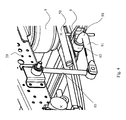
Fig. 4 shows an enlarged view of a portion offigure 1 . - In the drawings the same reference numbers and letters are used to identify the same elements or components.
- With reference to
figures 1 and2 , the suspension that is subject of the present invention is contrived to equip a narrow track industrial vehicle, namely with an overall width of the vehicle preferably lower than 250 cm. - The vehicle comprises a vehicle frame which consists of a pair of
side members cross members 23 and 23'. - The suspension subject of the invention comprises a
leaf spring 3 whosefirst end 31 and whosesecond end 32 are constrained to the vehicle frame. In particular, the first end is hinged to the frame, while the second end is hinged to anarm 33, the arm being hinged to the frame. Therefore, when a stress tends to rectify the leaf spring, thearm 33 allows an axial movement of theleaf spring 3. - A control arm 4 is placed over said leaf spring, that is beside its side that faces the
longitudinal member 22 of the vehicle. Afirst end 41 of the control arm is constrained to the frame together with saidfirst end 31 of theleaf spring 3, that is having the same hinging point, while asecond end 42, that can be seen infigure 1 , is constrained to the middle of theleaf spring 3. - Said control arm is suitable to cooperate with the leaf spring in the deflexion, being at least partially adherent with the leaf spring.
- The
second end 42 of the control arm comprises a bend toward the frame, so that on the extremity a U bolt can be inserted, having on its upper part apad 43 which has the function to deaden the blows of theend 42 of the control arm 4 to the frame, in particular when the stresses bring the suspension to the limit stop. This bend is a little beyond the middle of the leaf spring, as it can be seen infigure 2 . The position of said pad is particularly advantageous, since it is easily reachable when it needs to be replaced, and it is visible, hence it is easy to determine its wear state. - The
front axle 6 is connected to the lower part of theleaf spring 3, in correspondence of said middle area. It is U-shaped, so that thearms 61 bring thehub axis 7 above the control arm 4, as it can be seen infigure 2 . This is particularly advantageous because it allows to keep the height of the suspension low and therefore also the loading platform of the vehicle is kept low. - In correspondence of the interconnection between the
axle 3 and theleaf spring 3, apneumatic element 9 is placed between the leaf spring and theside member 22. - Thus it works between the
axle 6 of the wheels and theside member 22 undergoing compression stresses only, said two elements being particularly stiff. - A shock absorber 10 of any of the type known is placed beside said
pneumatic element 9. A first end of said shock absorber is hinged to saidsecond end 42 of the control arm 4, while a second end is constrained to the frame. - In particular, in order to allow the use of a shock absorber having an appropriate extension, but keeping the height of the suspension low, a
plate 221 is applied to theside member 22, to which saidsecond end 12 of theshock absorber 10 is hinged. The plate projects over theside member 22, externally with respect to the frame, that is on the side of the frame facing thehub 7 of the wheel. - Thus, as it can be seen in
figures 2 and3 , the shock absorber 10 works externally with respect to thepneumatic element 9 and it does not determine an increase of the height of the suspension. - Moreover, said shock absorber 10 is placed beside the
pneumatic element 9 at the minimum distance necessary for guaranteeing that the two elements do not interfere with each other, in particular during the compression of thepneumatic element 9. In particular, the shock absorber 10, in the side view offigure 2 , overlaps saidsecond end 42 of the control arm 4. Being the section of the shock absorber remarkably smaller than the pneumatic element, it does not extends towards the wheel more than thepneumatic element 9. - Moreover, the fact that the
suspension 1 comprises both apneumatic element 9, and aleaf spring 3 which cooperates with the control arm, allows thepneumatic element 9 to have small dimensions, and guarantees a low resonance frequency of the suspension. - Thanks to the disposition of the elements as described above and shown in the figures, the
rotochamber 71, integral with the relative caliper, and the relative pneumatic pipe do not interfere with the suspension system, even when an excessive wear of the pads makes the caliper move toward the inside of the vehicle, namely toward thepneumatic element 9. Thus, an industrial vehicle according to the present invention, for example being 220 cm wide, can guarantee a steering angle for example of 52° and 36° or wheel angle, respectively the external angle and the interior angle that the wheel can reach with respect to a longitudinal alignment. - According to another aspect of the invention, with reference to
figures 2 and3 , the caliper is placed above thehub 7, therefore the rotochamber is oriented in the twelve o'clock position with respect to the brake disc. Just under therotochamber 71, a connection element 72 projects from thehub 7 towards the longitudinal axle of the vehicle. In such connection element an articulated joint 51 is made for connecting to the steeringgear tie rod 50. Thus the articulated joint 51 is in a lower position with respect to therotochamber 71, without interfering with it. The figure also shows theactuator 52 of the assisted driving. - According to a further aspect of the invention, with reference to
figure 4 which shows an enlarged view of a portion offigure 1 , a higher stability is given to the vehicle by means of aU-shaped torsion bar 90, having a linear part parallel with theaxle 6 rotatably constrained to said axle by means of one ormore eyes 65. - Said
torsion bar 90, comprises, for each of its ends, an arm whose free end is hinged to the vehicle frame by means of a connectingrod 95, in order to define a coupling connecting rod-crank. - Taking as reference the axle of the
pneumatic element 9, thetorsion bar 90 is constrained to theaxle 6 on the opposite side with respect to the side where theshock absorber 10 is housed. Therefore the elements forming the torsion bar do not interfere with the shock absorber, being restrained in a space that does not interfere even with the rotation of the wheel of the vehicle during thehub movement 7. - The elements and the characteristics described in the different preferred embodiments may be combined without departing from the scope of the present invention.
- From the description set forth above it will be possible for the person skilled in the art to embody the invention with no need of describing further construction details.
Claims (10)
- Front suspension system for an industrial vehicle with full air braking system, comprising calipers equipped with a rotochamber (71), comprising: a leaf spring (3) hinged by a first (31) and a second end (32) to the frame (22) of said vehicle, said leaf spring (3) being connected below an axle (6); a control arm (4) whose first end (41) is hinged to the frame (22) of said vehicle and whose second end (42) is restricted above said connection of the leaf spring (3) with the axle (6); a pneumatic element (9) placed between said control arm (4) and said frame (22) above said connection of the leaf spring (3) with the axle (6).
- System according to the claim 1, further comprising a shock absorber (10) hinged between said second end (42) of said control arm (4) and the frame (22), externally to the frame by means of a plate (221) which projects over it.
- System according to any of the previous claims, wherein said second end (42) of said control arm (4) comprises a bend towards the frame to which a U bolt is connected having a limit stop pad (43) over it.
- System according to any of the previous claims, wherein said axle is U-shaped, and each one of its arms (61) has a hub (7) over the control arm (4).
- System according to any of the previous claims, wherein each hub comprises a caliper equipped with a rotochamber (72) placed over the hub (7), so that the rotochamber is oriented in the twelve o'clock position.
- System according to claim 5, wherein under the rotochamber (71), from the hub (7) towards the longitudinal axle of the vehicle a connection element (72) projects, wherein an articulated joint (51) is made for the connection to the steering gear tie rod (50).
- System according to any of the previous claims, further comprising a torsion bar (90) which comprises for each end an arm (91) whose free end is hinged to the vehicle frame by means of a connecting rod (95), in order to define a connecting rod-crank coupling, being a linear part of said torsion bar parallel with the axle (6) and rotatably constrained to said axle by means of two or more eyes (65).
- System according to claim 7, wherein said torsion bar (90) is constrained to the axle (6) on the opposite side with respect to the side where the shock absorber (10) is housed.
- Vehicle comprising a front suspension system according to any of the previous claims.
- Vehicle according to claim 9, having overall width lower than 250 cm.
Priority Applications (2)
| Application Number | Priority Date | Filing Date | Title |
|---|---|---|---|
| ES09425447T ES2389921T3 (en) | 2009-11-06 | 2009-11-06 | Front suspension system for an industrial vehicle with a complete pneumatic braking system |
| EP20090425447 EP2319716B1 (en) | 2009-11-06 | 2009-11-06 | Front suspension system for an industrial vehicle with full air braking system |
Applications Claiming Priority (1)
| Application Number | Priority Date | Filing Date | Title |
|---|---|---|---|
| EP20090425447 EP2319716B1 (en) | 2009-11-06 | 2009-11-06 | Front suspension system for an industrial vehicle with full air braking system |
Publications (2)
| Publication Number | Publication Date |
|---|---|
| EP2319716A1 true EP2319716A1 (en) | 2011-05-11 |
| EP2319716B1 EP2319716B1 (en) | 2012-06-27 |
Family
ID=42064247
Family Applications (1)
| Application Number | Title | Priority Date | Filing Date |
|---|---|---|---|
| EP20090425447 Active EP2319716B1 (en) | 2009-11-06 | 2009-11-06 | Front suspension system for an industrial vehicle with full air braking system |
Country Status (2)
| Country | Link |
|---|---|
| EP (1) | EP2319716B1 (en) |
| ES (1) | ES2389921T3 (en) |
Cited By (1)
| Publication number | Priority date | Publication date | Assignee | Title |
|---|---|---|---|---|
| US20230076886A1 (en) * | 2021-09-06 | 2023-03-09 | Wheel Pros, Llc | Easily Retrofittable Air Suspension Brackets, Method of Making and Method of Using. |
Citations (5)
| Publication number | Priority date | Publication date | Assignee | Title |
|---|---|---|---|---|
| NL8703122A (en) * | 1987-12-23 | 1989-07-17 | Weweler Nv | Vehicle air suspension - has axle mechanism including leaf spring with varying thickness |
| EP0352541A1 (en) * | 1988-07-23 | 1990-01-31 | Iveco Magirus Aktiengesellschaft | Resilient axle suspension for motor vehicles, in particular for utility vehicles |
| EP1375203A1 (en) * | 2002-06-26 | 2004-01-02 | IVECO FIAT S.p.A. | A mixed front suspension for a commercial vehicle |
| US20060208445A1 (en) * | 2005-03-16 | 2006-09-21 | Rowe Truck Equipment, Inc. | Suspension and steering system |
| US20070013160A1 (en) * | 2003-10-01 | 2007-01-18 | Gregory Richardson | Steer axle suspension |
-
2009
- 2009-11-06 ES ES09425447T patent/ES2389921T3/en active Active
- 2009-11-06 EP EP20090425447 patent/EP2319716B1/en active Active
Patent Citations (5)
| Publication number | Priority date | Publication date | Assignee | Title |
|---|---|---|---|---|
| NL8703122A (en) * | 1987-12-23 | 1989-07-17 | Weweler Nv | Vehicle air suspension - has axle mechanism including leaf spring with varying thickness |
| EP0352541A1 (en) * | 1988-07-23 | 1990-01-31 | Iveco Magirus Aktiengesellschaft | Resilient axle suspension for motor vehicles, in particular for utility vehicles |
| EP1375203A1 (en) * | 2002-06-26 | 2004-01-02 | IVECO FIAT S.p.A. | A mixed front suspension for a commercial vehicle |
| US20070013160A1 (en) * | 2003-10-01 | 2007-01-18 | Gregory Richardson | Steer axle suspension |
| US20060208445A1 (en) * | 2005-03-16 | 2006-09-21 | Rowe Truck Equipment, Inc. | Suspension and steering system |
Cited By (2)
| Publication number | Priority date | Publication date | Assignee | Title |
|---|---|---|---|---|
| US20230076886A1 (en) * | 2021-09-06 | 2023-03-09 | Wheel Pros, Llc | Easily Retrofittable Air Suspension Brackets, Method of Making and Method of Using. |
| US11745556B2 (en) * | 2021-09-06 | 2023-09-05 | Wheel Pros Llc | Easily retrofittable air suspension brackets, method of making and method of using |
Also Published As
| Publication number | Publication date |
|---|---|
| ES2389921T3 (en) | 2012-11-05 |
| EP2319716B1 (en) | 2012-06-27 |
Similar Documents
| Publication | Publication Date | Title |
|---|---|---|
| RU2562091C2 (en) | Independent suspension for spring-loaded controlled wheel | |
| RU2508998C2 (en) | Automotive dual lead suspension with j-shape spring | |
| US9096240B2 (en) | Bogie for railway vehicle with a suspension system | |
| EP1648722B1 (en) | Frame integrated rear suspension | |
| JP5702715B2 (en) | Vehicle suspension system | |
| US7850195B2 (en) | Tandem suspension for steerable axles | |
| US20100276901A1 (en) | Independent suspension and steering assembly | |
| US5016905A (en) | Tandem axle vehicle suspension system | |
| US10807430B2 (en) | Axle/suspension systems | |
| EP3126165B1 (en) | Double wishbone or mcpherson suspension with transverse leaf spring and dimensioning method thereof | |
| EP0897339A1 (en) | Suspensions system with laminated beam | |
| RU2487018C2 (en) | Stabiliser system for wheel axle suspension, and stabiliser | |
| EP1789268B1 (en) | Wheel suspension | |
| JPS60148709A (en) | Car suspension with prime mover | |
| EP2319716B1 (en) | Front suspension system for an industrial vehicle with full air braking system | |
| EP2990239B1 (en) | Semitrailer equipped with independent wheel suspension and air springs | |
| US20030102645A1 (en) | Arrangement for wheel suspension | |
| EP0887212A1 (en) | Off-road vehicle front wheel suspension | |
| AU2007201908A1 (en) | Trailer suspension | |
| US9902223B2 (en) | Couplable motor vehicle with improved coupling | |
| CN108608819B (en) | Trailer and suspension system thereof | |
| CA2342680A1 (en) | Suspension for a trailer having stub axles | |
| KR100423307B1 (en) | a structure of a rear axcel and suspention for 4WD vehicles | |
| KR100962200B1 (en) | Car Stabilizer Bar | |
| CN112659815A (en) | Trolley bus running system and trolley bus |
Legal Events
| Date | Code | Title | Description |
|---|---|---|---|
| PUAI | Public reference made under article 153(3) epc to a published international application that has entered the european phase |
Free format text: ORIGINAL CODE: 0009012 |
|
| AK | Designated contracting states |
Kind code of ref document: A1 Designated state(s): AT BE BG CH CY CZ DE DK EE ES FI FR GB GR HR HU IE IS IT LI LT LU LV MC MK MT NL NO PL PT RO SE SI SK SM TR |
|
| AX | Request for extension of the european patent |
Extension state: AL BA RS |
|
| 17P | Request for examination filed |
Effective date: 20111110 |
|
| GRAP | Despatch of communication of intention to grant a patent |
Free format text: ORIGINAL CODE: EPIDOSNIGR1 |
|
| RIC1 | Information provided on ipc code assigned before grant |
Ipc: B60G 7/04 20060101AFI20111208BHEP Ipc: B60T 17/08 20060101ALI20111208BHEP Ipc: B60G 11/44 20060101ALI20111208BHEP Ipc: B60G 11/46 20060101ALI20111208BHEP |
|
| GRAS | Grant fee paid |
Free format text: ORIGINAL CODE: EPIDOSNIGR3 |
|
| GRAA | (expected) grant |
Free format text: ORIGINAL CODE: 0009210 |
|
| AK | Designated contracting states |
Kind code of ref document: B1 Designated state(s): AT BE BG CH CY CZ DE DK EE ES FI FR GB GR HR HU IE IS IT LI LT LU LV MC MK MT NL NO PL PT RO SE SI SK SM TR |
|
| REG | Reference to a national code |
Ref country code: GB Ref legal event code: FG4D |
|
| REG | Reference to a national code |
Ref country code: CH Ref legal event code: EP |
|
| REG | Reference to a national code |
Ref country code: AT Ref legal event code: REF Ref document number: 563963 Country of ref document: AT Kind code of ref document: T Effective date: 20120715 |
|
| REG | Reference to a national code |
Ref country code: IE Ref legal event code: FG4D |
|
| REG | Reference to a national code |
Ref country code: DE Ref legal event code: R096 Ref document number: 602009007882 Country of ref document: DE Effective date: 20120823 |
|
| REG | Reference to a national code |
Ref country code: CH Ref legal event code: NV Representative=s name: N&G PATENT SERVICES SA |
|
| REG | Reference to a national code |
Ref country code: SE Ref legal event code: TRGR |
|
| PG25 | Lapsed in a contracting state [announced via postgrant information from national office to epo] |
Ref country code: NO Free format text: LAPSE BECAUSE OF FAILURE TO SUBMIT A TRANSLATION OF THE DESCRIPTION OR TO PAY THE FEE WITHIN THE PRESCRIBED TIME-LIMIT Effective date: 20120927 Ref country code: LT Free format text: LAPSE BECAUSE OF FAILURE TO SUBMIT A TRANSLATION OF THE DESCRIPTION OR TO PAY THE FEE WITHIN THE PRESCRIBED TIME-LIMIT Effective date: 20120627 Ref country code: FI Free format text: LAPSE BECAUSE OF FAILURE TO SUBMIT A TRANSLATION OF THE DESCRIPTION OR TO PAY THE FEE WITHIN THE PRESCRIBED TIME-LIMIT Effective date: 20120627 |
|
| REG | Reference to a national code |
Ref country code: NL Ref legal event code: T3 |
|
| REG | Reference to a national code |
Ref country code: ES Ref legal event code: FG2A Ref document number: 2389921 Country of ref document: ES Kind code of ref document: T3 Effective date: 20121105 |
|
| REG | Reference to a national code |
Ref country code: AT Ref legal event code: MK05 Ref document number: 563963 Country of ref document: AT Kind code of ref document: T Effective date: 20120627 |
|
| REG | Reference to a national code |
Ref country code: LT Ref legal event code: MG4D Effective date: 20120627 |
|
| PG25 | Lapsed in a contracting state [announced via postgrant information from national office to epo] |
Ref country code: GR Free format text: LAPSE BECAUSE OF FAILURE TO SUBMIT A TRANSLATION OF THE DESCRIPTION OR TO PAY THE FEE WITHIN THE PRESCRIBED TIME-LIMIT Effective date: 20120928 Ref country code: LV Free format text: LAPSE BECAUSE OF FAILURE TO SUBMIT A TRANSLATION OF THE DESCRIPTION OR TO PAY THE FEE WITHIN THE PRESCRIBED TIME-LIMIT Effective date: 20120627 Ref country code: SI Free format text: LAPSE BECAUSE OF FAILURE TO SUBMIT A TRANSLATION OF THE DESCRIPTION OR TO PAY THE FEE WITHIN THE PRESCRIBED TIME-LIMIT Effective date: 20120627 Ref country code: HR Free format text: LAPSE BECAUSE OF FAILURE TO SUBMIT A TRANSLATION OF THE DESCRIPTION OR TO PAY THE FEE WITHIN THE PRESCRIBED TIME-LIMIT Effective date: 20120627 |
|
| PG25 | Lapsed in a contracting state [announced via postgrant information from national office to epo] |
Ref country code: EE Free format text: LAPSE BECAUSE OF FAILURE TO SUBMIT A TRANSLATION OF THE DESCRIPTION OR TO PAY THE FEE WITHIN THE PRESCRIBED TIME-LIMIT Effective date: 20120627 Ref country code: RO Free format text: LAPSE BECAUSE OF FAILURE TO SUBMIT A TRANSLATION OF THE DESCRIPTION OR TO PAY THE FEE WITHIN THE PRESCRIBED TIME-LIMIT Effective date: 20120627 Ref country code: BE Free format text: LAPSE BECAUSE OF FAILURE TO SUBMIT A TRANSLATION OF THE DESCRIPTION OR TO PAY THE FEE WITHIN THE PRESCRIBED TIME-LIMIT Effective date: 20120627 Ref country code: CY Free format text: LAPSE BECAUSE OF FAILURE TO SUBMIT A TRANSLATION OF THE DESCRIPTION OR TO PAY THE FEE WITHIN THE PRESCRIBED TIME-LIMIT Effective date: 20120627 Ref country code: SK Free format text: LAPSE BECAUSE OF FAILURE TO SUBMIT A TRANSLATION OF THE DESCRIPTION OR TO PAY THE FEE WITHIN THE PRESCRIBED TIME-LIMIT Effective date: 20120627 Ref country code: AT Free format text: LAPSE BECAUSE OF FAILURE TO SUBMIT A TRANSLATION OF THE DESCRIPTION OR TO PAY THE FEE WITHIN THE PRESCRIBED TIME-LIMIT Effective date: 20120627 Ref country code: IS Free format text: LAPSE BECAUSE OF FAILURE TO SUBMIT A TRANSLATION OF THE DESCRIPTION OR TO PAY THE FEE WITHIN THE PRESCRIBED TIME-LIMIT Effective date: 20121027 Ref country code: CZ Free format text: LAPSE BECAUSE OF FAILURE TO SUBMIT A TRANSLATION OF THE DESCRIPTION OR TO PAY THE FEE WITHIN THE PRESCRIBED TIME-LIMIT Effective date: 20120627 |
|
| PG25 | Lapsed in a contracting state [announced via postgrant information from national office to epo] |
Ref country code: PT Free format text: LAPSE BECAUSE OF FAILURE TO SUBMIT A TRANSLATION OF THE DESCRIPTION OR TO PAY THE FEE WITHIN THE PRESCRIBED TIME-LIMIT Effective date: 20121029 Ref country code: PL Free format text: LAPSE BECAUSE OF FAILURE TO SUBMIT A TRANSLATION OF THE DESCRIPTION OR TO PAY THE FEE WITHIN THE PRESCRIBED TIME-LIMIT Effective date: 20120627 |
|
| PG25 | Lapsed in a contracting state [announced via postgrant information from national office to epo] |
Ref country code: DK Free format text: LAPSE BECAUSE OF FAILURE TO SUBMIT A TRANSLATION OF THE DESCRIPTION OR TO PAY THE FEE WITHIN THE PRESCRIBED TIME-LIMIT Effective date: 20120627 |
|
| PLBE | No opposition filed within time limit |
Free format text: ORIGINAL CODE: 0009261 |
|
| STAA | Information on the status of an ep patent application or granted ep patent |
Free format text: STATUS: NO OPPOSITION FILED WITHIN TIME LIMIT |
|
| 26N | No opposition filed |
Effective date: 20130328 |
|
| REG | Reference to a national code |
Ref country code: DE Ref legal event code: R097 Ref document number: 602009007882 Country of ref document: DE Effective date: 20130328 |
|
| PG25 | Lapsed in a contracting state [announced via postgrant information from national office to epo] |
Ref country code: BG Free format text: LAPSE BECAUSE OF FAILURE TO SUBMIT A TRANSLATION OF THE DESCRIPTION OR TO PAY THE FEE WITHIN THE PRESCRIBED TIME-LIMIT Effective date: 20120927 |
|
| REG | Reference to a national code |
Ref country code: IE Ref legal event code: MM4A |
|
| PG25 | Lapsed in a contracting state [announced via postgrant information from national office to epo] |
Ref country code: IE Free format text: LAPSE BECAUSE OF NON-PAYMENT OF DUE FEES Effective date: 20121106 |
|
| PG25 | Lapsed in a contracting state [announced via postgrant information from national office to epo] |
Ref country code: MT Free format text: LAPSE BECAUSE OF FAILURE TO SUBMIT A TRANSLATION OF THE DESCRIPTION OR TO PAY THE FEE WITHIN THE PRESCRIBED TIME-LIMIT Effective date: 20120627 |
|
| PG25 | Lapsed in a contracting state [announced via postgrant information from national office to epo] |
Ref country code: TR Free format text: LAPSE BECAUSE OF FAILURE TO SUBMIT A TRANSLATION OF THE DESCRIPTION OR TO PAY THE FEE WITHIN THE PRESCRIBED TIME-LIMIT Effective date: 20120627 Ref country code: MC Free format text: LAPSE BECAUSE OF NON-PAYMENT OF DUE FEES Effective date: 20121130 |
|
| PG25 | Lapsed in a contracting state [announced via postgrant information from national office to epo] |
Ref country code: LU Free format text: LAPSE BECAUSE OF NON-PAYMENT OF DUE FEES Effective date: 20121106 Ref country code: SM Free format text: LAPSE BECAUSE OF FAILURE TO SUBMIT A TRANSLATION OF THE DESCRIPTION OR TO PAY THE FEE WITHIN THE PRESCRIBED TIME-LIMIT Effective date: 20120627 |
|
| PG25 | Lapsed in a contracting state [announced via postgrant information from national office to epo] |
Ref country code: HU Free format text: LAPSE BECAUSE OF FAILURE TO SUBMIT A TRANSLATION OF THE DESCRIPTION OR TO PAY THE FEE WITHIN THE PRESCRIBED TIME-LIMIT Effective date: 20091106 |
|
| PG25 | Lapsed in a contracting state [announced via postgrant information from national office to epo] |
Ref country code: MK Free format text: LAPSE BECAUSE OF FAILURE TO SUBMIT A TRANSLATION OF THE DESCRIPTION OR TO PAY THE FEE WITHIN THE PRESCRIBED TIME-LIMIT Effective date: 20120627 |
|
| REG | Reference to a national code |
Ref country code: FR Ref legal event code: PLFP Year of fee payment: 7 |
|
| REG | Reference to a national code |
Ref country code: FR Ref legal event code: PLFP Year of fee payment: 8 |
|
| REG | Reference to a national code |
Ref country code: FR Ref legal event code: PLFP Year of fee payment: 9 |
|
| PGFP | Annual fee paid to national office [announced via postgrant information from national office to epo] |
Ref country code: CH Payment date: 20171114 Year of fee payment: 9 |
|
| PGFP | Annual fee paid to national office [announced via postgrant information from national office to epo] |
Ref country code: NL Payment date: 20181126 Year of fee payment: 10 |
|
| PGFP | Annual fee paid to national office [announced via postgrant information from national office to epo] |
Ref country code: SE Payment date: 20181126 Year of fee payment: 10 |
|
| PGFP | Annual fee paid to national office [announced via postgrant information from national office to epo] |
Ref country code: GB Payment date: 20181019 Year of fee payment: 16 |
|
| REG | Reference to a national code |
Ref country code: CH Ref legal event code: PL |
|
| GBPC | Gb: european patent ceased through non-payment of renewal fee |
Effective date: 20181106 |
|
| PG25 | Lapsed in a contracting state [announced via postgrant information from national office to epo] |
Ref country code: LI Free format text: LAPSE BECAUSE OF NON-PAYMENT OF DUE FEES Effective date: 20181130 Ref country code: CH Free format text: LAPSE BECAUSE OF NON-PAYMENT OF DUE FEES Effective date: 20181130 |
|
| PG25 | Lapsed in a contracting state [announced via postgrant information from national office to epo] |
Ref country code: GB Free format text: LAPSE BECAUSE OF NON-PAYMENT OF DUE FEES Effective date: 20181106 |
|
| REG | Reference to a national code |
Ref country code: SE Ref legal event code: EUG |
|
| REG | Reference to a national code |
Ref country code: NL Ref legal event code: MM Effective date: 20191201 |
|
| PG25 | Lapsed in a contracting state [announced via postgrant information from national office to epo] |
Ref country code: SE Free format text: LAPSE BECAUSE OF NON-PAYMENT OF DUE FEES Effective date: 20191107 |
|
| PG25 | Lapsed in a contracting state [announced via postgrant information from national office to epo] |
Ref country code: NL Free format text: LAPSE BECAUSE OF NON-PAYMENT OF DUE FEES Effective date: 20191201 |
|
| REG | Reference to a national code |
Ref country code: ES Ref legal event code: FD2A Effective date: 20210527 |
|
| PG25 | Lapsed in a contracting state [announced via postgrant information from national office to epo] |
Ref country code: ES Free format text: LAPSE BECAUSE OF NON-PAYMENT OF DUE FEES Effective date: 20191107 |
|
| P01 | Opt-out of the competence of the unified patent court (upc) registered |
Effective date: 20230523 |
|
| PGFP | Annual fee paid to national office [announced via postgrant information from national office to epo] |
Ref country code: DE Payment date: 20251126 Year of fee payment: 17 |
|
| PGFP | Annual fee paid to national office [announced via postgrant information from national office to epo] |
Ref country code: IT Payment date: 20251110 Year of fee payment: 17 |
|
| PGFP | Annual fee paid to national office [announced via postgrant information from national office to epo] |
Ref country code: FR Payment date: 20251124 Year of fee payment: 17 |