EP2319573A1 - Respiratory device for medication delivery. - Google Patents
Respiratory device for medication delivery. Download PDFInfo
- Publication number
- EP2319573A1 EP2319573A1 EP09425442A EP09425442A EP2319573A1 EP 2319573 A1 EP2319573 A1 EP 2319573A1 EP 09425442 A EP09425442 A EP 09425442A EP 09425442 A EP09425442 A EP 09425442A EP 2319573 A1 EP2319573 A1 EP 2319573A1
- Authority
- EP
- European Patent Office
- Prior art keywords
- valve
- operating position
- respiratory device
- pathway
- level
- Prior art date
- Legal status (The legal status is an assumption and is not a legal conclusion. Google has not performed a legal analysis and makes no representation as to the accuracy of the status listed.)
- Granted
Links
Images




Classifications
-
- A—HUMAN NECESSITIES
- A61—MEDICAL OR VETERINARY SCIENCE; HYGIENE
- A61M—DEVICES FOR INTRODUCING MEDIA INTO, OR ONTO, THE BODY; DEVICES FOR TRANSDUCING BODY MEDIA OR FOR TAKING MEDIA FROM THE BODY; DEVICES FOR PRODUCING OR ENDING SLEEP OR STUPOR
- A61M16/00—Devices for influencing the respiratory system of patients by gas treatment, e.g. ventilators; Tracheal tubes
- A61M16/08—Bellows; Connecting tubes ; Water traps; Patient circuits
- A61M16/0816—Joints or connectors
- A61M16/0833—T- or Y-type connectors, e.g. Y-piece
-
- A—HUMAN NECESSITIES
- A61—MEDICAL OR VETERINARY SCIENCE; HYGIENE
- A61M—DEVICES FOR INTRODUCING MEDIA INTO, OR ONTO, THE BODY; DEVICES FOR TRANSDUCING BODY MEDIA OR FOR TAKING MEDIA FROM THE BODY; DEVICES FOR PRODUCING OR ENDING SLEEP OR STUPOR
- A61M16/00—Devices for influencing the respiratory system of patients by gas treatment, e.g. ventilators; Tracheal tubes
- A61M16/08—Bellows; Connecting tubes ; Water traps; Patient circuits
- A61M16/0816—Joints or connectors
-
- A—HUMAN NECESSITIES
- A61—MEDICAL OR VETERINARY SCIENCE; HYGIENE
- A61M—DEVICES FOR INTRODUCING MEDIA INTO, OR ONTO, THE BODY; DEVICES FOR TRANSDUCING BODY MEDIA OR FOR TAKING MEDIA FROM THE BODY; DEVICES FOR PRODUCING OR ENDING SLEEP OR STUPOR
- A61M16/00—Devices for influencing the respiratory system of patients by gas treatment, e.g. ventilators; Tracheal tubes
- A61M16/10—Preparation of respiratory gases or vapours
- A61M16/1045—Devices for humidifying or heating the inspired gas by using recovered moisture or heat from the expired gas
-
- A—HUMAN NECESSITIES
- A61—MEDICAL OR VETERINARY SCIENCE; HYGIENE
- A61M—DEVICES FOR INTRODUCING MEDIA INTO, OR ONTO, THE BODY; DEVICES FOR TRANSDUCING BODY MEDIA OR FOR TAKING MEDIA FROM THE BODY; DEVICES FOR PRODUCING OR ENDING SLEEP OR STUPOR
- A61M16/00—Devices for influencing the respiratory system of patients by gas treatment, e.g. ventilators; Tracheal tubes
- A61M16/10—Preparation of respiratory gases or vapours
- A61M16/105—Filters
- A61M16/106—Filters in a path
- A61M16/107—Filters in a path in the inspiratory path
-
- A—HUMAN NECESSITIES
- A61—MEDICAL OR VETERINARY SCIENCE; HYGIENE
- A61M—DEVICES FOR INTRODUCING MEDIA INTO, OR ONTO, THE BODY; DEVICES FOR TRANSDUCING BODY MEDIA OR FOR TAKING MEDIA FROM THE BODY; DEVICES FOR PRODUCING OR ENDING SLEEP OR STUPOR
- A61M16/00—Devices for influencing the respiratory system of patients by gas treatment, e.g. ventilators; Tracheal tubes
- A61M16/10—Preparation of respiratory gases or vapours
- A61M16/14—Preparation of respiratory gases or vapours by mixing different fluids, one of them being in a liquid phase
-
- A—HUMAN NECESSITIES
- A61—MEDICAL OR VETERINARY SCIENCE; HYGIENE
- A61M—DEVICES FOR INTRODUCING MEDIA INTO, OR ONTO, THE BODY; DEVICES FOR TRANSDUCING BODY MEDIA OR FOR TAKING MEDIA FROM THE BODY; DEVICES FOR PRODUCING OR ENDING SLEEP OR STUPOR
- A61M16/00—Devices for influencing the respiratory system of patients by gas treatment, e.g. ventilators; Tracheal tubes
- A61M16/20—Valves specially adapted to medical respiratory devices
Definitions
- the present invention relates to a respiratory device capable of conditioning respiratory gases in combination with a path intended for medication delivery.
- Conditioning is intended as heating and humidification and/or filtration.
- the present invention is suitable for use connected to equipment for mechanical ventilation.
- the respiratory gases fed from the ventilator to the patient shall have adequate temperature level and moisture content because the patient has bypassed upper airways due to tracheal intubation.
- Heat and humidity can be added to respiratory gases through active humidifiers.
- prevention of heat and moisture loss from airways can be achieved by means of devices called HME (Heat and Moisture Exchanger) or artificial noses able to trap heat and humidity during exhalation and returning good portion of the same to the patient in inhalation phase.
- respiratory gases can be filtered through suitable means called antibacterial/antiviral filters.
- HME heat and moisture exchangers
- a patient connected to a mechanical ventilator also requires aerosol therapy.
- a nebulised medication is dispensed into the respiratory gases streamline.
- some passive humidification devices currently available on the market comprise an HME element positioned along the main channel, and an alternative path excluding the heat and moisture exchanger bypassing it.
- these devices have a selector that directs the air flow only towards the heat and moisture exchanger, when the humidification mode is required, and switches the flow of gases towards the bypass when the alternative medication mode is selected.
- the devices currently commercially available need to be switched manually from humidification mode to aerosol mode before to apply the medication and the possibility of human error in forgetting to perform this manoeuvre is present. At the same time, once the medication treatment is completed, the operator shall remember to switch back from aerosol to humidification mode.
- the technical purpose of the present invention is to overcome the drawbacks described above by providing a respiratory device capable of exchanging heat and moisture and/or filtering respiratory gases coupled with an alternative path for medication delivery.
- the present invention is aimed to provide a respiratory device capable of exchanging heat and moisture and/or filtering respiratory gases in combination with an alternative secondary path for aerosol delivery which is easy to operate for one person alone and which allows automatic switching from humidification to aerosol delivery mode upon insertion of an aerosol delivery device.
- This automatic system enhances safety of the device eliminating human error.
- Another purpose of the invention is to provide a respiratory device capable of exchanging heat and moisture and/or filtering respiratory gases in combination with an alternative secondary path for aerosol delivery which is simple and inexpensive to manufacture.
- a respiratory device capable of exchanging heat and moisture and/or filtering respiratory gases in combination with a secondary path for aerosol delivery, comprising the technical characteristics described in one or more of the claims below.
- the respiratory device 1 is positioned along the breathing circuit between Y-piece and patient interface (endotracheal or tracheostomy tube) conveying ventilation gases to a patient.
- a generic respiratory circuit is divided into a first section M upstream, located between the ventilator and the device, and a second section P downstream, located between the device and the patient.
- the device 1 comprises, in addition, a secondary pathway 21 defined, in the direction of the gases flow F from ventilator side to patient side respectively, by the inlet channel A, a second intermediate channel 6 and the outlet channel B.
- flow direction F is oriented from the section M of the main tube connected to the ventilator proceeding towards the section P of the main tube connected to the patient.
- Channels A and B are parts in common between pathway 20 and 21.
- the device 1 comprises an automatic valve 10 capable of selectively opening the second intermediate channel 6 and excluding the first intermediate channel 2 when required.
- valve 10 allows the flow of gases to pass through the primary pathway 20 only, while during aerosol therapy the valve 10 allows the flow of gases and nebulised medication to pass through the secondary pathway 21 only.
- the external element 11 can be an adapter with means for dispensing drugs contained in a metered dose inhaler (MDI), not illustrated.
- MDI metered dose inhaler
- the reference numeral 11 generally indicates both a nebulizer, shown with broken lines, and MDI adapter.
- the valve 10 is movable between a first operating position where only the primary pathway 20 is active and a second operating position where only the secondary pathway 21 is active.
- valve 10 in the first operating position the valve 10 is in fluid communication with the first intermediate channel 2 while in the second operating position the valve 10 is in fluid communication with the second intermediate channel 6.
- in fluid communication means that there is a fluid connection between said parts.
- valve 10 After coupling of the valve 10 to an external element 11, the valve 10 itself moves from the first operating position ( Figures 3 and 7 ) to the second operating position ( Figures 4 and 8 ); the removal of the element 11 deactivates the valve 10 and returns it to the first operating position ( Figures 3 and 7 ).
- valve 10 The movement of the valve 10 from the second position back to the first position is facilitated by opposing means 12.
- This opposing means 12 serves also to keep the valve 10 in the first position when no medication delivery is performed.
- the opposing means 12 comprises a helical spring which is partially compressed and loaded when the valve 10 is in the rest position and is further compressed and loaded when the element 11 is coupled to the valve 10 thereby moving the valve 10 into the second operating position.
- Figures 9 and 10 show that the automatic valve 10 is a two-way valve and comprises a main body 13 divided into a first level 14 and a second level 15 by a central septum 16.
- the main body 13 has a cylindrical form extending along the longitudinal axis 13a.
- the first level 14 defines the pathway 20 for the gases flow only, while the second level 15 defines the pathway 21 for the flow of gases and nebulised medication.
- both the first level 14 and the second level 15 comprise opening/closing means 22 which defines the pathway 20 for the flow of gases and the pathway 21 for the flow of gases and nebulised medication, closing alternatively the second intermediate channel 6 and the first intermediate channel 2.
- the flow of gases coming from ventilator enters the inlet channel A of the device 1, passes through the first level 14 of the valve 10, flows into the first intermediate channel 2 passing through the conditioning member 40, then leaves through the outlet channel B of the device 1 and passes onwards to the patient.
- the respiratory gases exhaled during normal respiration follows the same path but in the opposite direction.
- valve 10 is actuated and the flow of respiratory gases mixed with nebulised medication passes through the second intermediate channel 6 up to the outlet channel B of the device 1 and onwards to the patient.
- FIGS. 1 to 4 and also Figure 9 show a first embodiment of the device 1 according to the present invention which will now be described.
- the device 1 has a substantially compact configuration.
- the valve 10 is aligned with a first section of the first intermediate channel 2 and is at right angles to the second intermediate channel 6.
- the second intermediate channel 6 has a longitudinal axis 6a parallel to the axis 3a of the housing 3 of the heat and moisture exchanger element 4 and/or filter element 5 (i.e. the conditioning member 40).
- Figure 9 shows a detailed view of the main body 13 of the valve 10 according to the first embodiment of the device 1, in which the first level 14 has the opening/closing means 22 comprising the finger nail 23.
- the nail 23 defines an inside surface for the flow of gases along the primary pathway 20.
- the nail 23 of the first level 14 is designed to close the second intermediate channel 6.
- the opening/closing means 22 has at least one wall 24 which extends at right angles to the septum 16.
- This wall 24 has a transversal channel C, visible in Figure 9 , for the passage of the flow of gases and nebulised medication when the valve 10 is in the second operating position.
- the septum 16 closes the first intermediate channel 2 to enable the passage of the flow of gases and nebulised medication along the second intermediate channel 6, through the secondary pathway 21.
- valve 10 is in the first operating position ( Figure 3 ).
- the external element 11 dispensing the nebulised medication or more generically a therapeutic substance, is coupled to the valve 10. This coupling moves the valve 10 into the second operating position. In this position, the first level 14 moves forward inside the first intermediate channel 2 and the septum 16 thereby closes off access to the first intermediate channel 2 itself.
- This second embodiment has a double-Y shaped configuration where the inlet channel A of the device 1 divides, at the first joint 8 upstream the conditioning member 40, into a primary pathway 20 and a secondary pathway 21.
- the primary pathway 20 comprises the first intermediate channel 2 and the housing 3 of the member 40 placed in the middle of the channel 2 itself.
- the opening/closing means 22 comprises on the first level 14, at least one wall 24 designed to close the second intermediate channel 6, and to define the primary pathway 20 for the flow of gases along the first intermediate channel 2 only, when the valve 10 is in its first operating position ( Figures 7 and 10 ).
- the main body 13 there are two walls 24 ( Figure 10 ) between which there is a transversal channel D which defines the primary pathway 20 for the flow of respiratory gases.
- the opening/closing means 22 comprises, on the second level 15, a nail 23 designed to close the first intermediate channel 2, when the automatic valve 10 is in the second operating position, as shown in Figure 8 .
- This second embodiment also has opposing means, a spring 12, suitably housed inside containing means 27, which tends to return the valve 10 from the second operating position to the first operating position ( Figure 6 ).
- the first level 14 is in fluid communication with the inlet channel A of the device 1 and with the first intermediate channel 2.
- the external element 11 is coupled to the valve 10.
- the valve 10 is pushed into the second operating position, the spring 12 is compressed and the second level 15 of the main body 13 of the valve 10 is activated.
- the second level 15 is in fluid communication with the inlet channel A of the device 1 and with the second intermediate channel 6.
- the present invention has notable advantages and achieves the purposes described above.
- the channel for the required operating mode is selected automatically when the valve is coupled to the aerosol/medication dispensing element.
- the operator can be certain that the device is set for the normal respiration mode.
- the device is easy for a single operator to use and provides a clear, precise visual indication of the device operating mode currently selected.
Landscapes
- Health & Medical Sciences (AREA)
- Emergency Medicine (AREA)
- Pulmonology (AREA)
- Engineering & Computer Science (AREA)
- Anesthesiology (AREA)
- Biomedical Technology (AREA)
- Heart & Thoracic Surgery (AREA)
- Hematology (AREA)
- Life Sciences & Earth Sciences (AREA)
- Animal Behavior & Ethology (AREA)
- General Health & Medical Sciences (AREA)
- Public Health (AREA)
- Veterinary Medicine (AREA)
- Respiratory Apparatuses And Protective Means (AREA)
Abstract
Description
- The present invention relates to a respiratory device capable of conditioning respiratory gases in combination with a path intended for medication delivery.
- Conditioning is intended as heating and humidification and/or filtration.
- In particular, the present invention is suitable for use connected to equipment for mechanical ventilation.
- During mechanical ventilation, the respiratory gases fed from the ventilator to the patient shall have adequate temperature level and moisture content because the patient has bypassed upper airways due to tracheal intubation. Heat and humidity can be added to respiratory gases through active humidifiers. In alternative, prevention of heat and moisture loss from airways can be achieved by means of devices called HME (Heat and Moisture Exchanger) or artificial noses able to trap heat and humidity during exhalation and returning good portion of the same to the patient in inhalation phase. In addition, respiratory gases can be filtered through suitable means called antibacterial/antiviral filters.
- In the present application, "respiratory gases" is intended to identify either air or other gas mixture indifferently.
- These respiratory devices are therefore fitted with suitable members able to act as heat and moisture exchangers (HME) and filters.
- Frequently, a patient connected to a mechanical ventilator also requires aerosol therapy.
- In this case, a nebulised medication is dispensed into the respiratory gases streamline.
- It is important that the flow of gases conveying the nebulised medication does not pass through said member (the HME and/or filter) because the medication would otherwise be partially absorbed by the member itself. This would result in the waste of medication, inefficiency of treatment and also lead to deterioration and clogging of the member (exchanger/filtering element).
- To overcome this drawback, some passive humidification devices currently available on the market comprise an HME element positioned along the main channel, and an alternative path excluding the heat and moisture exchanger bypassing it.
- Inside, these devices have a selector that directs the air flow only towards the heat and moisture exchanger, when the humidification mode is required, and switches the flow of gases towards the bypass when the alternative medication mode is selected.
- A drawback pointed out is that the diverter must be switched manually by the operator. Selecting from one operating position to another is not always easy especially if the device is being operated by one person alone as is often the case in hospitals or when patients are receiving treatment at home. During operation of the diverter, the device must be kept in position by the operator ensuring that it does not detach from the portion of respiratory circuit that conveys respiratory gases from the ventilator to the patient.
- The devices which are currently commercially available have at least three components to be handled during the switching phase and this factor clearly complicates matters when a person has to operate the device alone.
- Furthermore, the devices currently commercially available need to be switched manually from humidification mode to aerosol mode before to apply the medication and the possibility of human error in forgetting to perform this manoeuvre is present. At the same time, once the medication treatment is completed, the operator shall remember to switch back from aerosol to humidification mode.
- The technical purpose of the present invention is to overcome the drawbacks described above by providing a respiratory device capable of exchanging heat and moisture and/or filtering respiratory gases coupled with an alternative path for medication delivery.
- In particular, the present invention is aimed to provide a respiratory device capable of exchanging heat and moisture and/or filtering respiratory gases in combination with an alternative secondary path for aerosol delivery which is easy to operate for one person alone and which allows automatic switching from humidification to aerosol delivery mode upon insertion of an aerosol delivery device. This automatic system enhances safety of the device eliminating human error.
- Another purpose of the invention is to provide a respiratory device capable of exchanging heat and moisture and/or filtering respiratory gases in combination with an alternative secondary path for aerosol delivery which is simple and inexpensive to manufacture.
- The technical purpose and aims specified are substantially achieved by a respiratory device capable of exchanging heat and moisture and/or filtering respiratory gases in combination with a secondary path for aerosol delivery, comprising the technical characteristics described in one or more of the claims below.
- Further features and advantages of the present invention will become apparent from the description below of a preferred embodiment shown in the annexed drawings, given purely by way of a nonlimiting example, in which:
-
Figure 1 is a perspective view of a first embodiment of the device according to the present invention; -
Figure 2 is an exploded view of the device shown inFigure 1 ; -
Figure 3 is a cross-section of the device shown inFigure 1 in a first operating position; -
Figure 4 is a cross-section of the device shown inFigure 1 in a second operating position; -
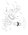
Figure 5 is a perspective view of a second embodiment of the device according to the present invention; -
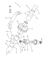
Figure 6 is an exploded view of the device shown inFigure 5 ; -
Figure 7 is a cross-section of the device shown inFigure 5 in a first operating position; -
Figure 8 is a cross-section of the device shown inFigure 5 in a second operating position; -
Figure 9 is an enlarged view of a component of the device shown inFigure 2 ; -
Figure 10 is an enlarged view of a component of the device shown inFigure 6 . - In the drawings, the
numeral 1 denotes in its entirety a respiratory device capable of exchanging heat and moisture and/or filtering respiratory gases in combination with a secondary conduit dedicated to convey aerosol. - The
respiratory device 1 is positioned along the breathing circuit between Y-piece and patient interface (endotracheal or tracheostomy tube) conveying ventilation gases to a patient. - In this way, a generic respiratory circuit is divided into a first section M upstream, located between the ventilator and the device, and a second section P downstream, located between the device and the patient.
- The device is connected to an aerosol delivery device enabling to perform aerosol therapy.
- As described below, the present invention comprises two alternative paths, one designed exclusively for the passage of gases for normal respiration, and the other exclusively for the passage of gases and nebulised medication.
- The
device 1 comprises aprimary pathway 20 defined by an inlet channel A, a firstintermediate channel 2, anhousing 3 and an outlet channel B. - The
housing 3 contains aconditioning member 40 which in the preferred embodiments shown comprises a heat andmoisture exchanger element 4 and afiltering element 5. - According to different embodiments not shown of the present invention, the
conditioning member 40 comprises either a heat and moisture exchanger or a filtering element. - When gases travel along
primary pathway 20, gases flow through theconditioning member 40. - The
device 1 comprises, in addition, asecondary pathway 21 defined, in the direction of the gases flow F from ventilator side to patient side respectively, by the inlet channel A, a secondintermediate channel 6 and the outlet channel B. With reference to any of the drawings, flow direction F is oriented from the section M of the main tube connected to the ventilator proceeding towards the section P of the main tube connected to the patient. - Channels A and B are parts in common between
pathway - Both the
primary pathway 20 and thesecondary pathway 21 are selectively and alternately in fluid communication with the main respiratory tube when thedevice 1 is incorporated in the respiratory circuit. - The
device 1 comprises anautomatic valve 10 capable of selectively opening the secondintermediate channel 6 and excluding the firstintermediate channel 2 when required. - In other words, during normal respiration the
valve 10 allows the flow of gases to pass through theprimary pathway 20 only, while during aerosol therapy thevalve 10 allows the flow of gases and nebulised medication to pass through thesecondary pathway 21 only. - Advantageously, the
automatic valve 10 is located in correspondence of inlet channel A wherepathway 20 andpathway 21 differentiate one from the other. In other words, theautomatic valve 10 is located, with reference to thepathway 20, between the inlet channel A and the firstintermediate channel 2, and with reference to thepathway 21, between the inlet channel A and the secondintermediate channel 6. Thedevice 1 has, in the inlet channel A, a single tube which then divides into the firstintermediate channel 2 and the secondintermediate channel 6. Downstream thehousing 3, the separatedprimary pathway 20 and thesecondary pathway 21 join to form a single tube which defines the outlet channel B of thedevice 1. - The
valve 10 is automatic and is actuated by simply coupling thevalve 10 itself to anexternal element 11. Theexternal element 11 can be for example a nebulizer containing a therapeutic substance or medication, to be nebulised. - Alternatively, the
external element 11 can be an adapter with means for dispensing drugs contained in a metered dose inhaler (MDI), not illustrated. InFigure 5 thereference numeral 11 generally indicates both a nebulizer, shown with broken lines, and MDI adapter. - The
valve 10 is movable between a first operating position where only theprimary pathway 20 is active and a second operating position where only thesecondary pathway 21 is active. - In other words, in the first operating position the
valve 10 is in fluid communication with the firstintermediate channel 2 while in the second operating position thevalve 10 is in fluid communication with the secondintermediate channel 6. - In the present description the expression "in fluid communication" referred to different parts means that there is a fluid connection between said parts.
- After coupling of the
valve 10 to anexternal element 11, thevalve 10 itself moves from the first operating position (Figures 3 and7 ) to the second operating position (Figures 4 and8 ); the removal of theelement 11 deactivates thevalve 10 and returns it to the first operating position (Figures 3 and7 ). - The movement of the
valve 10 from the second position back to the first position is facilitated by opposingmeans 12. This opposing means 12 serves also to keep thevalve 10 in the first position when no medication delivery is performed. - The opposing means 12 comprises a helical spring which is partially compressed and loaded when the
valve 10 is in the rest position and is further compressed and loaded when theelement 11 is coupled to thevalve 10 thereby moving thevalve 10 into the second operating position. - When the
element 11 is removed, on the other hand, thespring 12, compressed and loaded, acts on thevalve 10 to return it to the rest position, pushing it into the first operating position (Figures 3 and7 ) . -
Figures 9 and 10 show that theautomatic valve 10 is a two-way valve and comprises amain body 13 divided into afirst level 14 and asecond level 15 by acentral septum 16. - In a preferred embodiment, the
main body 13 has a cylindrical form extending along thelongitudinal axis 13a. - The
first level 14 defines thepathway 20 for the gases flow only, while thesecond level 15 defines thepathway 21 for the flow of gases and nebulised medication. - In particular, both the
first level 14 and thesecond level 15 comprise opening/closing means 22 which defines thepathway 20 for the flow of gases and thepathway 21 for the flow of gases and nebulised medication, closing alternatively the secondintermediate channel 6 and the firstintermediate channel 2. - Preferably, the opening/closing means 22 comprises at least a
finger nail 23 and at least awall 24. The term 'finger nail' in this description is to be understood as a portion of the cylindrical wall as clearly shown in the drawing. - During ventilation, the flow of gases coming from ventilator enters the inlet channel A of the
device 1, passes through thefirst level 14 of thevalve 10, flows into the firstintermediate channel 2 passing through theconditioning member 40, then leaves through the outlet channel B of thedevice 1 and passes onwards to the patient. The respiratory gases exhaled during normal respiration follows the same path but in the opposite direction. - During aerosol therapy by means of the
element 11 thevalve 10 is actuated and the flow of respiratory gases mixed with nebulised medication passes through the secondintermediate channel 6 up to the outlet channel B of thedevice 1 and onwards to the patient. - The
main body 13 of thevalve 10 comprises in addition apin 25 which extends along theaxis 13a from theseptum 16 through the side of thesecond level 15. Thepin 25 has a first end connected to theseptum 16 and a secondfree end 25a opposite to the first end. Thefree end 25a is connected to apusher disc 26, parallel to theseptum 16, which acts as a support surface for theexternal element 11. In other words, theexternal element 11 presses against thepusher disc 26 to move thevalve 10 from the first operating position to the second operating position. -
Figures 1 to 4 and alsoFigure 9 show a first embodiment of thedevice 1 according to the present invention which will now be described. - In the first embodiment of the present invention, the
device 1 has a substantially compact configuration. Thevalve 10 is aligned with a first section of the firstintermediate channel 2 and is at right angles to the secondintermediate channel 6. The secondintermediate channel 6 has alongitudinal axis 6a parallel to theaxis 3a of thehousing 3 of the heat andmoisture exchanger element 4 and/or filter element 5 (i.e. the conditioning member 40). -
Figure 9 shows a detailed view of themain body 13 of thevalve 10 according to the first embodiment of thedevice 1, in which thefirst level 14 has the opening/closing means 22 comprising thefinger nail 23. When theautomatic valve 10 is in the first operating position, thenail 23 defines an inside surface for the flow of gases along theprimary pathway 20. - In the first operating position of the
valve 10 therefore, thenail 23 of thefirst level 14 is designed to close the secondintermediate channel 6. - On the
second level 15, the opening/closing means 22 has at least onewall 24 which extends at right angles to theseptum 16. Thiswall 24 has a transversal channel C, visible inFigure 9 , for the passage of the flow of gases and nebulised medication when thevalve 10 is in the second operating position. - In this first embodiment, when the
automatic valve 10 is in the second operating position, theseptum 16 closes the firstintermediate channel 2 to enable the passage of the flow of gases and nebulised medication along the secondintermediate channel 6, through thesecondary pathway 21. - Between the
septum 16 and thepusher disc 26 there is an opposing means 12 (Figure 2 ). - The opposing means 12, suitably housed inside containing means 27, preferably comprises a spring pushing the
valve 10 from the second operating position to the first operating position. - During use, when the
device 1 is used for normal respiration, thevalve 10 is in the first operating position (Figure 3 ). - In this position, the
second level 15 of themain body 13 is completely housed in the containing seat V of thevalve 10. Thefirst level 14, on the other hand, is in fluid communication with the inlet channel A of thedevice 1. Thenail 23 closes access to the secondintermediate channel 6 so that the flow of gases can only flow towards the firstintermediate channel 2 through theprimary pathway 20 and through theconditioning member 40, then leaving thehousing 3 through the outlet channel B of thedevice 1 into which also the secondintermediate channel 6 is inserted. - When the
device 1 is in the aerosol therapy mode, as shown inFigure 4 , theexternal element 11 dispensing the nebulised medication or more generically a therapeutic substance, is coupled to thevalve 10. This coupling moves thevalve 10 into the second operating position. In this position, thefirst level 14 moves forward inside the firstintermediate channel 2 and theseptum 16 thereby closes off access to the firstintermediate channel 2 itself. - The
second level 15 moving forward, leaves the containing seat V of thevalve 10 and moves into fluid communication with the inlet channel A of thedevice 1. Thepathway 21 passes through a transversal channel C to put the inlet channel A into fluid communication with thesecond channel 6.Figures 5 to 8 and alsoFigure 10 show a second embodiment of thedevice 1 according to the present invention. - This second embodiment has a double-Y shaped configuration where the inlet channel A of the
device 1 divides, at the first joint 8 upstream theconditioning member 40, into aprimary pathway 20 and asecondary pathway 21. - The
primary pathway 20 comprises the firstintermediate channel 2 and thehousing 3 of themember 40 placed in the middle of thechannel 2 itself. - Thus, the first
intermediate channel 2 and the secondintermediate channel 6 form a first Y-shape at the first joint 8 upstream. - The two
intermediate channels conditioning member 40, to form a second Y-shape, at the second joint 9 where the outlet channel B of thedevice 1 starts. - The
valve 10 is at right angles to the containing plane of the twointermediate channels first level 14, at least onewall 24 designed to close the secondintermediate channel 6, and to define theprimary pathway 20 for the flow of gases along the firstintermediate channel 2 only, when thevalve 10 is in its first operating position (Figures 7 and10 ). - In a preferred embodiment of the
main body 13, there are two walls 24 (Figure 10 ) between which there is a transversal channel D which defines theprimary pathway 20 for the flow of respiratory gases. - The opening/closing means 22 comprises, on the
second level 15, anail 23 designed to close the firstintermediate channel 2, when theautomatic valve 10 is in the second operating position, as shown inFigure 8 . This defines asecondary pathway 21, indicated inFigure 6 , for the flow of gases and medication which is diverted towards the secondintermediate channel 6 only. - This second embodiment also has opposing means, a
spring 12, suitably housed inside containing means 27, which tends to return thevalve 10 from the second operating position to the first operating position (Figure 6 ). - In particular, in this case the opposing means 12 is positioned between the
septum 16 and abottom wall 28 of the space V housing thevalve 10 on the side of thefirst level 14. - In this case also, when the
valve 10 is in the first operating position, thefirst level 14 is in fluid communication with the inlet channel A of thedevice 1 and with the firstintermediate channel 2. During aerosol therapy, theexternal element 11 is coupled to thevalve 10. Thevalve 10 is pushed into the second operating position, thespring 12 is compressed and thesecond level 15 of themain body 13 of thevalve 10 is activated. In this configuration, thesecond level 15 is in fluid communication with the inlet channel A of thedevice 1 and with the secondintermediate channel 6. - The present invention has notable advantages and achieves the purposes described above.
- The presence of an automatic valve prevents any risk of human error in positioning the flow diverter when switching backwards and forwards between the normal respiration and the aerosol therapy modes.
- The channel for the required operating mode is selected automatically when the valve is coupled to the aerosol/medication dispensing element. When no aerosol/medication dispensing element is present, the operator can be certain that the device is set for the normal respiration mode.
- The device is easy for a single operator to use and provides a clear, precise visual indication of the device operating mode currently selected.
Claims (22)
- A respiratory device for conditioning respiratory gases, comprising
a primary pathway (20) and
a housing (3) placed in fluid communication with the primary pathway (20) and containing a conditioning member (40),
a secondary pathway (21) for medication delivery connected to the primary pathway (20) both upstream and downstream the housing (3) referring to a direction (F) of the flow of gases, characterised in that it comprises an automatic valve (10) capable of selectively activating the secondary pathway (21) and excluding the primary pathway (20); the automatic valve (10) being activated when an external element (11) is coupled to it. - The respiratory device according to claim 1, in which said primary and secondary pathways (20, 21) have a common inlet channel (A), characterized in that said automatic valve (10) is positioned in correspondence of said inlet channel (A).
- The respiratory device according to one of the foregoing claims, characterised in that the automatic valve (10) is movable between a first operating position where only the primary pathway (20) is active and a second operating position where only the secondary pathway (21) is active.
- The respiratory device according to any of claims 1 to 3, characterised in that the valve (10) is actuated automatically by coupling it to an external element (11) so that it moves into the second operating position, and is deactivated by removing the element (11) so that it returns to the first operating position.
- The respiratory device according to any of claims 1 to 4, characterised in that it comprises opposing means (12) designed to hold or return the valve (10) in the first operating position.
- The respiratory device according to claim 5, characterised in that the opposing means (12) comprises a helical spring, said spring being compressed and loaded by the valve (10) when the external element (11) is coupled to the valve (10) which is thereby pushed into the second operating position and which is extended in the rest position when the valve (10) is in the first operating position.
- The respiratory device according to any of claims 1 to 6, characterised in that the automatic valve (10) is a two-way valve and comprises a main body (13) divided into a first level (14) and a second level (15) by a central septum (16).
- The respiratory device according to claim 7, characterised in that the first level (14) and the second level (15) comprise opening/closing means (22) which let the gases flowing through the primary pathway (20) on the first level (14) and the gases mixed with a nebulised medication through the secondary pathway (21) on the second level (15), closing respectively and alternatively the secondary pathway (21) and the primary pathway (20).
- The respiratory device according to claim 7 or 8, characterised in that said main body (13) comprises a pin (25) which extends axially and centrally from the septum (16) towards the second level (15).
- The respiratory device according to claim 9, characterised in that the main body (13) comprises a pusher disc (26) connected to the free end (25a) of the pin (25); the pusher disc (26) defining a support surface for the external element (11) which is coupled to the valve (10).
- The respiratory device according to claim 10, characterised in that the opening/closing means (22) comprises, on the first level (14), a nail (23) designed to close the secondary pathway (21) when the automatic valve (10) is in the first operating position, so as to allow the flow of gases only along the primary pathway (20).
- The respiratory device according to claim 11, characterised in that the second level (15) has at least one wall (24) which extends at right angles to the septum (16) and which has a transversal channel (C) for the passage of the flow of gases and nebulised medication through the secondary pathway (21) when the valve (10) is in the second operating position.
- The respiratory device according to claim 12, characterised in that when the automatic valve (10) is in the second operating position, the septum (16) closes the primary pathway (20) to enable the passage of the gases mixed with the nebulised medication along the secondary pathway (21).
- The respiratory device according to claim 13, characterised in that, between the septum (16) and the pusher disc (26), it comprises opposing means (12) that tends to return the valve (10) from the second operating position to the first operating position.
- The respiratory device according to claim 10, characterised in that the opening/closing means (22) comprises, on the first level (14), at least one wall (24) designed to close the secondary pathway (21) allowing the flow of gases through the primary pathway (20) only when the valve (10) is in its first operating position.
- The respiratory device according to claim 15, characterised in that the opening/closing means (22) comprises, on the first level (14), two walls (24) between which there is a transversal channel (D) for the passage of the flow of gases through the primary pathway (20) when the valve (10) is in the first operating position; one of the walls (24) being designed to close the secondary pathway (21) when the valve (10) is in its first operating position.
- The respiratory device according to claim 15 or 16, characterised in that the opening/closing means (22) comprises, on the second level (15), a nail (23) designed to close the primary pathway (20) when the automatic valve (10) is in the second operating position so as to enable the passage of gases mixed with nebulised medication along the secondary pathway (21).
- The respiratory device according to claim 17, characterised in that it comprises opposing means (12) which tends to return the valve (10) from the second operating position to the first operating position, said means (12) being positioned between the septum (16) and a bottom wall (28) of a space (V) housing the valve (10), on the side of the first level (14).
- The respiratory device according to any of claims 1 to 18, characterised in that said conditioning member (40) comprises a heat and moisture exchanger element (4).
- The respiratory device according to any of claims 1 to 18, characterised in that said conditioning member (40) comprises a filtering element (5).
- The respiratory device according to any of claims 1 to 18, characterised in that said conditioning member (40) comprises both a heat and moisture exchanger element (4) and a filtering element (5).
- A ventilator system characterized in that it comprises a respiratory device as set out in any of claims 1 to 21.
Priority Applications (1)
| Application Number | Priority Date | Filing Date | Title |
|---|---|---|---|
| EP09425442A EP2319573B1 (en) | 2009-11-04 | 2009-11-04 | Respiratory device for medication delivery. |
Applications Claiming Priority (1)
| Application Number | Priority Date | Filing Date | Title |
|---|---|---|---|
| EP09425442A EP2319573B1 (en) | 2009-11-04 | 2009-11-04 | Respiratory device for medication delivery. |
Publications (2)
| Publication Number | Publication Date |
|---|---|
| EP2319573A1 true EP2319573A1 (en) | 2011-05-11 |
| EP2319573B1 EP2319573B1 (en) | 2012-07-04 |
Family
ID=42045335
Family Applications (1)
| Application Number | Title | Priority Date | Filing Date |
|---|---|---|---|
| EP09425442A Not-in-force EP2319573B1 (en) | 2009-11-04 | 2009-11-04 | Respiratory device for medication delivery. |
Country Status (1)
| Country | Link |
|---|---|
| EP (1) | EP2319573B1 (en) |
Cited By (2)
| Publication number | Priority date | Publication date | Assignee | Title |
|---|---|---|---|---|
| WO2016070394A1 (en) * | 2014-11-07 | 2016-05-12 | 深圳迈瑞生物医疗电子股份有限公司 | Exhaling valve |
| US11351327B2 (en) | 2016-02-09 | 2022-06-07 | Drägerwerk AG & Co. KGaA | HME device for use in a breathing circuit of a ventilation system |
Citations (5)
| Publication number | Priority date | Publication date | Assignee | Title |
|---|---|---|---|---|
| DE29805569U1 (en) * | 1998-03-27 | 1998-07-30 | SchuF-Chemieventile Vertriebs-GmbH & Co. KG, 65931 Frankfurt | Two-way polymer valve |
| EP1192968A1 (en) * | 2000-09-29 | 2002-04-03 | DHD Healthcare Corporation | HME bypass system |
| US20040123974A1 (en) * | 2002-09-16 | 2004-07-01 | Marler Gregory S. | Heat and moisture filter exchanger and method |
| US20080210242A1 (en) * | 2006-06-12 | 2008-09-04 | Marc Alan Burk | Mask-nebulizer-metered-dose-inhaler assembly |
| WO2009149290A1 (en) * | 2008-06-05 | 2009-12-10 | Allegiance Corporation | Heat and moisture exchange unit with check valve |
-
2009
- 2009-11-04 EP EP09425442A patent/EP2319573B1/en not_active Not-in-force
Patent Citations (5)
| Publication number | Priority date | Publication date | Assignee | Title |
|---|---|---|---|---|
| DE29805569U1 (en) * | 1998-03-27 | 1998-07-30 | SchuF-Chemieventile Vertriebs-GmbH & Co. KG, 65931 Frankfurt | Two-way polymer valve |
| EP1192968A1 (en) * | 2000-09-29 | 2002-04-03 | DHD Healthcare Corporation | HME bypass system |
| US20040123974A1 (en) * | 2002-09-16 | 2004-07-01 | Marler Gregory S. | Heat and moisture filter exchanger and method |
| US20080210242A1 (en) * | 2006-06-12 | 2008-09-04 | Marc Alan Burk | Mask-nebulizer-metered-dose-inhaler assembly |
| WO2009149290A1 (en) * | 2008-06-05 | 2009-12-10 | Allegiance Corporation | Heat and moisture exchange unit with check valve |
Cited By (4)
| Publication number | Priority date | Publication date | Assignee | Title |
|---|---|---|---|---|
| WO2016070394A1 (en) * | 2014-11-07 | 2016-05-12 | 深圳迈瑞生物医疗电子股份有限公司 | Exhaling valve |
| CN106922131A (en) * | 2014-11-07 | 2017-07-04 | 深圳迈瑞生物医疗电子股份有限公司 | an exhalation valve |
| CN106922131B (en) * | 2014-11-07 | 2019-07-23 | 深圳迈瑞生物医疗电子股份有限公司 | an exhalation valve |
| US11351327B2 (en) | 2016-02-09 | 2022-06-07 | Drägerwerk AG & Co. KGaA | HME device for use in a breathing circuit of a ventilation system |
Also Published As
| Publication number | Publication date |
|---|---|
| EP2319573B1 (en) | 2012-07-04 |
Similar Documents
| Publication | Publication Date | Title |
|---|---|---|
| AU782790B2 (en) | HME bypass system | |
| CN101896216B (en) | Patient cassette with variable patient circuit volume | |
| US7624731B2 (en) | HME/MDI apparatus having MDI in parallel to HME | |
| US6976488B2 (en) | Medication bypass heat and moisture exchange unit | |
| EP2898917B1 (en) | Bypass system for respiratory therapy and anaesthesia | |
| EP2371410B1 (en) | Arrangement and method for ventilating lungs | |
| KR101999938B1 (en) | System and method for preventing cross contamination in a flow generating system | |
| US8539950B2 (en) | Method and apparatus for collection of waste anesthetic gases | |
| US8561606B2 (en) | Heat and moisture exchange unit | |
| US20110197889A1 (en) | Arrangement and method for supplying breathing gas for respiration | |
| US11291792B2 (en) | Pulmonary ventilator with changeable filters | |
| US9737679B2 (en) | Automated HME with nebulizer connection | |
| EP2301615B1 (en) | Respiratory device for medication delivery | |
| EP2319573B1 (en) | Respiratory device for medication delivery. | |
| WO2020236860A1 (en) | Mechanical ventilation circuit with wet nebulization | |
| US20240149005A1 (en) | Hme devices | |
| CN103372255A (en) | Arrangement and method for guiding expired respiratory gas flow and breathing circuit for ventilating lungs of a subject | |
| US20240123178A1 (en) | Gas-treatment devices | |
| CN113082441A (en) | Anesthesia machine gas circuit system and anesthesia machine |
Legal Events
| Date | Code | Title | Description |
|---|---|---|---|
| PUAI | Public reference made under article 153(3) epc to a published international application that has entered the european phase |
Free format text: ORIGINAL CODE: 0009012 |
|
| 17P | Request for examination filed |
Effective date: 20101008 |
|
| AK | Designated contracting states |
Kind code of ref document: A1 Designated state(s): AT BE BG CH CY CZ DE DK EE ES FI FR GB GR HR HU IE IS IT LI LT LU LV MC MK MT NL NO PL PT RO SE SI SK SM TR |
|
| AX | Request for extension of the european patent |
Extension state: AL BA RS |
|
| GRAP | Despatch of communication of intention to grant a patent |
Free format text: ORIGINAL CODE: EPIDOSNIGR1 |
|
| GRAS | Grant fee paid |
Free format text: ORIGINAL CODE: EPIDOSNIGR3 |
|
| GRAA | (expected) grant |
Free format text: ORIGINAL CODE: 0009210 |
|
| AK | Designated contracting states |
Kind code of ref document: B1 Designated state(s): AT BE BG CH CY CZ DE DK EE ES FI FR GB GR HR HU IE IS IT LI LT LU LV MC MK MT NL NO PL PT RO SE SI SK SM TR |
|
| REG | Reference to a national code |
Ref country code: GB Ref legal event code: FG4D |
|
| REG | Reference to a national code |
Ref country code: CH Ref legal event code: EP |
|
| REG | Reference to a national code |
Ref country code: AT Ref legal event code: REF Ref document number: 564897 Country of ref document: AT Kind code of ref document: T Effective date: 20120715 |
|
| REG | Reference to a national code |
Ref country code: IE Ref legal event code: FG4D |
|
| REG | Reference to a national code |
Ref country code: DE Ref legal event code: R096 Ref document number: 602009008041 Country of ref document: DE Effective date: 20120830 |
|
| REG | Reference to a national code |
Ref country code: AT Ref legal event code: MK05 Ref document number: 564897 Country of ref document: AT Kind code of ref document: T Effective date: 20120704 |
|
| REG | Reference to a national code |
Ref country code: NL Ref legal event code: VDEP Effective date: 20120704 |
|
| PG25 | Lapsed in a contracting state [announced via postgrant information from national office to epo] |
Ref country code: SI Free format text: LAPSE BECAUSE OF FAILURE TO SUBMIT A TRANSLATION OF THE DESCRIPTION OR TO PAY THE FEE WITHIN THE PRESCRIBED TIME-LIMIT Effective date: 20120704 |
|
| REG | Reference to a national code |
Ref country code: LT Ref legal event code: MG4D Effective date: 20120704 |
|
| PG25 | Lapsed in a contracting state [announced via postgrant information from national office to epo] |
Ref country code: NO Free format text: LAPSE BECAUSE OF FAILURE TO SUBMIT A TRANSLATION OF THE DESCRIPTION OR TO PAY THE FEE WITHIN THE PRESCRIBED TIME-LIMIT Effective date: 20121004 Ref country code: HR Free format text: LAPSE BECAUSE OF FAILURE TO SUBMIT A TRANSLATION OF THE DESCRIPTION OR TO PAY THE FEE WITHIN THE PRESCRIBED TIME-LIMIT Effective date: 20120704 Ref country code: LT Free format text: LAPSE BECAUSE OF FAILURE TO SUBMIT A TRANSLATION OF THE DESCRIPTION OR TO PAY THE FEE WITHIN THE PRESCRIBED TIME-LIMIT Effective date: 20120704 Ref country code: CY Free format text: LAPSE BECAUSE OF FAILURE TO SUBMIT A TRANSLATION OF THE DESCRIPTION OR TO PAY THE FEE WITHIN THE PRESCRIBED TIME-LIMIT Effective date: 20120704 Ref country code: BE Free format text: LAPSE BECAUSE OF FAILURE TO SUBMIT A TRANSLATION OF THE DESCRIPTION OR TO PAY THE FEE WITHIN THE PRESCRIBED TIME-LIMIT Effective date: 20120704 Ref country code: AT Free format text: LAPSE BECAUSE OF FAILURE TO SUBMIT A TRANSLATION OF THE DESCRIPTION OR TO PAY THE FEE WITHIN THE PRESCRIBED TIME-LIMIT Effective date: 20120704 Ref country code: FI Free format text: LAPSE BECAUSE OF FAILURE TO SUBMIT A TRANSLATION OF THE DESCRIPTION OR TO PAY THE FEE WITHIN THE PRESCRIBED TIME-LIMIT Effective date: 20120704 Ref country code: IS Free format text: LAPSE BECAUSE OF FAILURE TO SUBMIT A TRANSLATION OF THE DESCRIPTION OR TO PAY THE FEE WITHIN THE PRESCRIBED TIME-LIMIT Effective date: 20121104 |
|
| PG25 | Lapsed in a contracting state [announced via postgrant information from national office to epo] |
Ref country code: PT Free format text: LAPSE BECAUSE OF FAILURE TO SUBMIT A TRANSLATION OF THE DESCRIPTION OR TO PAY THE FEE WITHIN THE PRESCRIBED TIME-LIMIT Effective date: 20121105 Ref country code: LV Free format text: LAPSE BECAUSE OF FAILURE TO SUBMIT A TRANSLATION OF THE DESCRIPTION OR TO PAY THE FEE WITHIN THE PRESCRIBED TIME-LIMIT Effective date: 20120704 Ref country code: SE Free format text: LAPSE BECAUSE OF FAILURE TO SUBMIT A TRANSLATION OF THE DESCRIPTION OR TO PAY THE FEE WITHIN THE PRESCRIBED TIME-LIMIT Effective date: 20120704 Ref country code: PL Free format text: LAPSE BECAUSE OF FAILURE TO SUBMIT A TRANSLATION OF THE DESCRIPTION OR TO PAY THE FEE WITHIN THE PRESCRIBED TIME-LIMIT Effective date: 20120704 Ref country code: GR Free format text: LAPSE BECAUSE OF FAILURE TO SUBMIT A TRANSLATION OF THE DESCRIPTION OR TO PAY THE FEE WITHIN THE PRESCRIBED TIME-LIMIT Effective date: 20121005 |
|
| PG25 | Lapsed in a contracting state [announced via postgrant information from national office to epo] |
Ref country code: NL Free format text: LAPSE BECAUSE OF FAILURE TO SUBMIT A TRANSLATION OF THE DESCRIPTION OR TO PAY THE FEE WITHIN THE PRESCRIBED TIME-LIMIT Effective date: 20120704 |
|
| PG25 | Lapsed in a contracting state [announced via postgrant information from national office to epo] |
Ref country code: EE Free format text: LAPSE BECAUSE OF FAILURE TO SUBMIT A TRANSLATION OF THE DESCRIPTION OR TO PAY THE FEE WITHIN THE PRESCRIBED TIME-LIMIT Effective date: 20120704 Ref country code: CZ Free format text: LAPSE BECAUSE OF FAILURE TO SUBMIT A TRANSLATION OF THE DESCRIPTION OR TO PAY THE FEE WITHIN THE PRESCRIBED TIME-LIMIT Effective date: 20120704 Ref country code: ES Free format text: LAPSE BECAUSE OF FAILURE TO SUBMIT A TRANSLATION OF THE DESCRIPTION OR TO PAY THE FEE WITHIN THE PRESCRIBED TIME-LIMIT Effective date: 20121015 Ref country code: DK Free format text: LAPSE BECAUSE OF FAILURE TO SUBMIT A TRANSLATION OF THE DESCRIPTION OR TO PAY THE FEE WITHIN THE PRESCRIBED TIME-LIMIT Effective date: 20120704 Ref country code: RO Free format text: LAPSE BECAUSE OF FAILURE TO SUBMIT A TRANSLATION OF THE DESCRIPTION OR TO PAY THE FEE WITHIN THE PRESCRIBED TIME-LIMIT Effective date: 20120704 |
|
| PLBE | No opposition filed within time limit |
Free format text: ORIGINAL CODE: 0009261 |
|
| STAA | Information on the status of an ep patent application or granted ep patent |
Free format text: STATUS: NO OPPOSITION FILED WITHIN TIME LIMIT |
|
| PG25 | Lapsed in a contracting state [announced via postgrant information from national office to epo] |
Ref country code: SK Free format text: LAPSE BECAUSE OF FAILURE TO SUBMIT A TRANSLATION OF THE DESCRIPTION OR TO PAY THE FEE WITHIN THE PRESCRIBED TIME-LIMIT Effective date: 20120704 |
|
| 26N | No opposition filed |
Effective date: 20130405 |
|
| PG25 | Lapsed in a contracting state [announced via postgrant information from national office to epo] |
Ref country code: BG Free format text: LAPSE BECAUSE OF FAILURE TO SUBMIT A TRANSLATION OF THE DESCRIPTION OR TO PAY THE FEE WITHIN THE PRESCRIBED TIME-LIMIT Effective date: 20121004 |
|
| REG | Reference to a national code |
Ref country code: DE Ref legal event code: R097 Ref document number: 602009008041 Country of ref document: DE Effective date: 20130405 |
|
| REG | Reference to a national code |
Ref country code: IE Ref legal event code: MM4A |
|
| PG25 | Lapsed in a contracting state [announced via postgrant information from national office to epo] |
Ref country code: IE Free format text: LAPSE BECAUSE OF NON-PAYMENT OF DUE FEES Effective date: 20121104 |
|
| PG25 | Lapsed in a contracting state [announced via postgrant information from national office to epo] |
Ref country code: MT Free format text: LAPSE BECAUSE OF FAILURE TO SUBMIT A TRANSLATION OF THE DESCRIPTION OR TO PAY THE FEE WITHIN THE PRESCRIBED TIME-LIMIT Effective date: 20120704 |
|
| PG25 | Lapsed in a contracting state [announced via postgrant information from national office to epo] |
Ref country code: MC Free format text: LAPSE BECAUSE OF NON-PAYMENT OF DUE FEES Effective date: 20121130 Ref country code: TR Free format text: LAPSE BECAUSE OF FAILURE TO SUBMIT A TRANSLATION OF THE DESCRIPTION OR TO PAY THE FEE WITHIN THE PRESCRIBED TIME-LIMIT Effective date: 20120704 |
|
| PG25 | Lapsed in a contracting state [announced via postgrant information from national office to epo] |
Ref country code: LU Free format text: LAPSE BECAUSE OF NON-PAYMENT OF DUE FEES Effective date: 20121104 Ref country code: SM Free format text: LAPSE BECAUSE OF FAILURE TO SUBMIT A TRANSLATION OF THE DESCRIPTION OR TO PAY THE FEE WITHIN THE PRESCRIBED TIME-LIMIT Effective date: 20120704 |
|
| REG | Reference to a national code |
Ref country code: CH Ref legal event code: PL |
|
| PG25 | Lapsed in a contracting state [announced via postgrant information from national office to epo] |
Ref country code: LI Free format text: LAPSE BECAUSE OF NON-PAYMENT OF DUE FEES Effective date: 20131130 Ref country code: CH Free format text: LAPSE BECAUSE OF NON-PAYMENT OF DUE FEES Effective date: 20131130 Ref country code: HU Free format text: LAPSE BECAUSE OF FAILURE TO SUBMIT A TRANSLATION OF THE DESCRIPTION OR TO PAY THE FEE WITHIN THE PRESCRIBED TIME-LIMIT Effective date: 20091104 |
|
| PG25 | Lapsed in a contracting state [announced via postgrant information from national office to epo] |
Ref country code: MK Free format text: LAPSE BECAUSE OF FAILURE TO SUBMIT A TRANSLATION OF THE DESCRIPTION OR TO PAY THE FEE WITHIN THE PRESCRIBED TIME-LIMIT Effective date: 20120704 |
|
| REG | Reference to a national code |
Ref country code: FR Ref legal event code: PLFP Year of fee payment: 7 |
|
| REG | Reference to a national code |
Ref country code: FR Ref legal event code: PLFP Year of fee payment: 8 |
|
| REG | Reference to a national code |
Ref country code: FR Ref legal event code: PLFP Year of fee payment: 9 |
|
| REG | Reference to a national code |
Ref country code: FR Ref legal event code: PLFP Year of fee payment: 10 |
|
| PGFP | Annual fee paid to national office [announced via postgrant information from national office to epo] |
Ref country code: FR Payment date: 20201021 Year of fee payment: 12 |
|
| PG25 | Lapsed in a contracting state [announced via postgrant information from national office to epo] |
Ref country code: FR Free format text: LAPSE BECAUSE OF NON-PAYMENT OF DUE FEES Effective date: 20211130 |
|
| PGFP | Annual fee paid to national office [announced via postgrant information from national office to epo] |
Ref country code: IT Payment date: 20221020 Year of fee payment: 14 |
|
| PGFP | Annual fee paid to national office [announced via postgrant information from national office to epo] |
Ref country code: GB Payment date: 20231019 Year of fee payment: 15 |
|
| PGFP | Annual fee paid to national office [announced via postgrant information from national office to epo] |
Ref country code: DE Payment date: 20231019 Year of fee payment: 15 |
|
| PG25 | Lapsed in a contracting state [announced via postgrant information from national office to epo] |
Ref country code: IT Free format text: LAPSE BECAUSE OF NON-PAYMENT OF DUE FEES Effective date: 20231104 |
|
| PG25 | Lapsed in a contracting state [announced via postgrant information from national office to epo] |
Ref country code: IT Free format text: LAPSE BECAUSE OF NON-PAYMENT OF DUE FEES Effective date: 20231104 |
|
| REG | Reference to a national code |
Ref country code: DE Ref legal event code: R119 Ref document number: 602009008041 Country of ref document: DE |
|
| GBPC | Gb: european patent ceased through non-payment of renewal fee |
Effective date: 20241104 |
|
| PG25 | Lapsed in a contracting state [announced via postgrant information from national office to epo] |
Ref country code: DE Free format text: LAPSE BECAUSE OF NON-PAYMENT OF DUE FEES Effective date: 20250603 |
|
| PG25 | Lapsed in a contracting state [announced via postgrant information from national office to epo] |
Ref country code: GB Free format text: LAPSE BECAUSE OF NON-PAYMENT OF DUE FEES Effective date: 20241104 |