EP2317866B1 - Method and device for producing confectionery - Google Patents
Method and device for producing confectionery Download PDFInfo
- Publication number
- EP2317866B1 EP2317866B1 EP08790040A EP08790040A EP2317866B1 EP 2317866 B1 EP2317866 B1 EP 2317866B1 EP 08790040 A EP08790040 A EP 08790040A EP 08790040 A EP08790040 A EP 08790040A EP 2317866 B1 EP2317866 B1 EP 2317866B1
- Authority
- EP
- European Patent Office
- Prior art keywords
- wafer
- stage
- wafers
- carousel
- conveyor
- Prior art date
- Legal status (The legal status is an assumption and is not a legal conclusion. Google has not performed a legal analysis and makes no representation as to the accuracy of the status listed.)
- Not-in-force
Links
- 235000009508 confectionery Nutrition 0.000 title claims abstract description 37
- 238000000034 method Methods 0.000 title claims abstract description 22
- 235000012431 wafers Nutrition 0.000 claims abstract description 121
- 238000004519 manufacturing process Methods 0.000 claims abstract description 17
- 238000011049 filling Methods 0.000 claims abstract description 16
- 239000007788 liquid Substances 0.000 claims abstract description 16
- 235000021056 liquid food Nutrition 0.000 claims abstract description 7
- 235000021057 semi-liquid food Nutrition 0.000 claims abstract description 7
- 238000011068 loading method Methods 0.000 claims abstract description 5
- 238000012856 packing Methods 0.000 claims abstract description 4
- 235000013305 food Nutrition 0.000 claims description 18
- 230000005484 gravity Effects 0.000 claims description 4
- 230000009471 action Effects 0.000 claims description 3
- 239000011796 hollow space material Substances 0.000 claims description 3
- 230000003213 activating effect Effects 0.000 claims 1
- 239000000463 material Substances 0.000 abstract 1
- 239000006071 cream Substances 0.000 description 5
- 239000010410 layer Substances 0.000 description 4
- 230000006866 deterioration Effects 0.000 description 3
- 235000015243 ice cream Nutrition 0.000 description 2
- 230000004913 activation Effects 0.000 description 1
- 230000008859 change Effects 0.000 description 1
- 235000019219 chocolate Nutrition 0.000 description 1
- 239000011247 coating layer Substances 0.000 description 1
- 238000001125 extrusion Methods 0.000 description 1
- 238000002156 mixing Methods 0.000 description 1
- 238000004806 packaging method and process Methods 0.000 description 1
- 230000002093 peripheral effect Effects 0.000 description 1
- 230000008569 process Effects 0.000 description 1
- 230000000284 resting effect Effects 0.000 description 1
Images



Classifications
-
- A—HUMAN NECESSITIES
- A23—FOODS OR FOODSTUFFS; TREATMENT THEREOF, NOT COVERED BY OTHER CLASSES
- A23G—COCOA; COCOA PRODUCTS, e.g. CHOCOLATE; SUBSTITUTES FOR COCOA OR COCOA PRODUCTS; CONFECTIONERY; CHEWING GUM; ICE-CREAM; PREPARATION THEREOF
- A23G3/00—Sweetmeats; Confectionery; Marzipan; Coated or filled products
- A23G3/02—Apparatus specially adapted for manufacture or treatment of sweetmeats or confectionery; Accessories therefor
- A23G3/20—Apparatus for coating or filling sweetmeats or confectionery
- A23G3/2007—Manufacture of filled articles, composite articles, multi-layered articles
-
- A—HUMAN NECESSITIES
- A23—FOODS OR FOODSTUFFS; TREATMENT THEREOF, NOT COVERED BY OTHER CLASSES
- A23G—COCOA; COCOA PRODUCTS, e.g. CHOCOLATE; SUBSTITUTES FOR COCOA OR COCOA PRODUCTS; CONFECTIONERY; CHEWING GUM; ICE-CREAM; PREPARATION THEREOF
- A23G3/00—Sweetmeats; Confectionery; Marzipan; Coated or filled products
- A23G3/0002—Processes of manufacture not relating to composition and compounding ingredients
- A23G3/0063—Coating or filling sweetmeats or confectionery
- A23G3/0065—Processes for making filled articles, composite articles, multi-layered articles
-
- A—HUMAN NECESSITIES
- A23—FOODS OR FOODSTUFFS; TREATMENT THEREOF, NOT COVERED BY OTHER CLASSES
- A23G—COCOA; COCOA PRODUCTS, e.g. CHOCOLATE; SUBSTITUTES FOR COCOA OR COCOA PRODUCTS; CONFECTIONERY; CHEWING GUM; ICE-CREAM; PREPARATION THEREOF
- A23G9/00—Frozen sweets, e.g. ice confectionery, ice-cream; Mixtures therefor
- A23G9/04—Production of frozen sweets, e.g. ice-cream
- A23G9/22—Details, component parts or accessories of apparatus insofar as not peculiar to a single one of the preceding groups
- A23G9/28—Details, component parts or accessories of apparatus insofar as not peculiar to a single one of the preceding groups for portioning or dispensing
- A23G9/288—Details, component parts or accessories of apparatus insofar as not peculiar to a single one of the preceding groups for portioning or dispensing for finishing or filling ice-cream cones or other edible containers; Manipulating methods therefor
Definitions
- the invention relates to a method and a machine for production of sweet confectionery foods in general and in particular those destined to be arranged, immediately following the production process, in a predetermined orientation.
- the sweet products the present invention makes particular reference to are an external cone-shaped wafer containing a sweet product, especially a cream or the like.
- Confectionery products of the above type i.e. comprising an external wafer in the form of a cone containing a sweet product, are commonly constituted by packaged ice-cream cones.
- Machines for the production of ice cream cones comprising a carousel and a plurality of work stations arranged about the rotation axis of the carousel for realising successive work stages of the confectionery product, which is held up by the rotating carousel by means of special support seatings.
- the cones When they arrive in an unloading station, the cones are expelled from the support seatings and placed, in any order, on a conveyor belt which takes them to a following packaging unit.
- the cones are laid on the conveyor practically horizontally and entirely haphazardly, and can actually move as the cones might roll on the conveyor surface, so that the cones might change position during transport.
- Producer machines of the above-described type are disadvantageously incompatible with the production of cone-shaped confectionery products containing a product in the liquid or semi-liquid state.
- These confectionery products immediately after they are made, contain a cream or a similar product which is still hot and thus in the liquid or semiliquid state, and cannot be laid horizontally on the conveyor belt due to the risk of the cream's exiting, which would cause irreparable damage to the sweet product as well as fouling the conveyor.
- Document US 4942910 discloses a process and apparatus for making a shaped frozen confection.
- the apparatus has a plurality of nozzles for extruding the shaped confection in a variety of contoured shapes.
- the nozzles simultaneously move in a vertical direction and circularly in a horizontal direction, thereby moving in a spiral path to produce a spirally-shaped frozen confection.
- a variety of differently shaped frozen confections can be made by varying the rate of extrusion from the nozzles, or the rate or direction of vertical movement of the nozzles.
- Document US 3070933 discloses A machine for manufacturing confectionary products comprising a frame structure, a horizontal loading wheel rotatably carried by the frame structure, means for intermittently rotating said wheel, confectionary dispensing units carried on said frame structure in functional relation to said wheel, means for actuating said dispensers, said means including a shaft disposed through the center of the wheel, means for reciprocating the shaft, and means connecting the reciprocating shaft to the dispensers.
- Document US 3025983 discloses a candy tray for reception of a plurality of cups filled with candy.
- the tray comprises a tray lower portion and a tray upper portion, said upper portion comprising a top wall and a peripheral flange depending from staid top wall and having an open bottom.
- the top wall has a plurality of holes sized and shaped for reception of said cups with each said cup extending slidably through a respective bore and resting upon a bottom wall. The distance between the upper surface of said top wall and said bottom wall is less than the height of said cups.
- a technical aim of the present invention is to provide a method and a machine for production of confectionery products which do not suffer from the above-described drawbacks.
- An aim of the present invention is to provide a method and a machine for production of confectionery products which enables a correct production of products having a conformation which is unsuitable for being laid stably on a horizontal transport plane, and more in particular a cone conformation.
- a further aim of the invention is to provide a method and a machine for the production of confectionery products which enable a correct production of confectionery products containing a liquid or semiliquid product, in particular cream or the like.
- a further objective of the invention is a machine for the production of confectionery products of the present invention, having the characteristics expressed in claim 11 and/or in one or more of the claims depending thereon.
- 100 denotes a confectionery product obtained using the method and the machine of the present invention.
- the confectionery product 100 shown in a section view to include the contents thereof, comprises a conical wafer 101 which, in the illustrated embodiment of figure 9 , is provided with an inlet mouth facing upwards and a point facing downwards.
- the wafer 101 Internally of the wafer 101 is a first layer of a first food product 102 on which a second layer of a second food product 103 is arranged.
- the first food product is chocolate-based whereas the second is cream-based.
- the two food products are in the liquid or semiliquid state, preferably having a creamy texture.
- a coating layer is deposited on the upper surface of the second layer, preferably made of a granulated foodstuff, such as nuts.
- the inlet mouth of the wafer 101 is closed by a circular lid 105.
- the wafer 101 is further externally covered with a covering 106 made of wrapping paper which superiorly exhibits an end flap 107 folded on the lid 105 to block the lid 105 stably on the wafer 101.
- 1 denotes in its entirety a machine for realising the confectionery product 100 of figure 9 .
- the machine 1 comprises a conveyor device, with might also have a straight development, but preferably comprises a carousel 2 which is rotatable about an axis X and which has a plurality of support seatings 3 for containing wafers 101 with the inlet mouth thereof facing upwards.
- the rotation axis X of the carousel 2 is vertical.
- the support seatings 3 are arranged over a whole angular development of the carousel 2 about the rotation axis X and, in the illustrated embodiment, they are grouped in ten groups each constituted by six support seatings 3.
- the groups, which are angularly equidistanced about the rotation axis X, are each made up of two rows of three seatings 3, arranged side by side in a radial direction.
- the machine 1 comprises:
- the carousel 2 is rotatable about the rotation axis X in order to bring the support seatings 3 through all the mentioned stations in the above-described order.
- the above-described stations are well visible in figures 2 and 3 .
- the third filling station 8 might be omitted, or one of the first two filling stations 6, 7 could be omitted, or the third filling station 8 and one of the first two filling stations 6 7 could be omitted.
- the loading stations 4, 5 supply wafers 101, preferably pre-wrapped in paper, i.e. having the covering 106 already externally applied.
- the filling stations 6, 7, 8 pour a predetermined quantity of food product into the wafer 101 through the inlet mouth of the wafer 101.
- the filling of the wafer 101 might be partial or complete, according to the confectionery product 100 to be produced.
- the first and the second food products 102, 103 are poured into the wafer 101 while in the liquid or semiliquid state, preferably in the creamy state.
- the two food products might need to be heated and therefore to be at above ambient temperature, preferably comprised between 10°C and 60°C. In this case, given the rapidity of the functioning of the machine, the product remains in the liquid state up to when it reaches the outlet station 11, and even beyond.
- the filling stations 6, 7, 8 are of a type comprising a hopper or upper tank, a plurality of dispensing nozzles (six, one for each underlying support seating 3) and an intermediate dispensing unit, where necessary powered by an electric motor.
- the closing station 9 comprises a mobile support 12, rotatable about a horizontal axis 12a and vertically slidable on guides 12b.
- the mobile support 12 is provided with six units 12c each of which is positionable at one of the support seatings 3 in order to apply a lid 105 onto a wafer 101.
- the mobile support 12 assumes a removal configuration, in which it is arranged at the top of the guides 12b in order to enable the units 12c (facing upwards) to remove respective lids 105 from a same number of piles P of lids 105, and an application position in which it lowers and turns the units 12c downwards in order to apply the lids 105 on the underlying wafers 101.
- the following folding station 10 comprises six pressers 13 which lower towards the underlying wafers 101 in order to fold the upper flaps 107 of the above-described covering 106 of the wafers 101.
- a conveyor 14 is located at the outlet station 11, which is immediately downstream of the folding station 10, which conveyor 14 has the function of conveying the wafers 101 to successive work stations (not illustrated), for example packing or marking stations, or others beside.
- figure 9 clearly shows that the conveyor 14 comprises two parallel segments, 14a, 14b, each of which receives and conveys the wafers 101 coming from a respective row of three of each group of six wafers 101 arranged on the carousel 2.
- the conveyor 14, during the transport of the filled wafers 101 advantageously keeps the wafers 101 in a vertical orientation, i.e. with the inlet mouth facing upwards to prevent exit of the food products 102, 103.
- the wafers 101 are closed by the lids 105, the food products 102, 103 contained thereof are still in the liquid or semiliquid state and might drip through folds in the covering 106 should the wafers 101 be arranged horizontally or in any case in an incorrect position.
- a wrong positioning of the wafers 101 might also create undesired reciprocal mixing of the food products 102, 103 and the granulated foodstuff 104, causing a deterioration of the confectionery product 100 which would no longer be fit for sale.
- each filled and packed wafer 101 is supported, while on the conveyor 14, at opposite sides thereof such as to be automatically orientated in a vertical direction under the action of its own weight.
- each segment 14a, 14b comprises two parallel bands 15 which face one another and are distanced in order to define a hollow space 16 in which the lower point of the conical wafer 101 inserts.
- the parallel bands 15 are mobile in an advancement direction A in order to convey the wafers 101 away from the carousel 2 while they support the wafers 101 thanks to the fact that the upper part of the wafers 101 has a transversal dimension which is greater than the hollow space 16 and thus rests on the parallel sides 15.
- the parallel bands are preferably defined by facing parallel branches of two conveyors having parallel belts.
- the machine 1 further comprises means for transfer, arranged at the outlet station 11 and acting between the carousel 2 and the conveyor 14 to remove the wafers 101 from the carousel 2 and deposit them on the transporter 14.
- the means for transfer primarily comprise a pusher 17 which raises the filled and packed wafers 101 from the respective support seatings 3.
- the pusher 17 exhibits six terminals 17a each of which intercepts the lower portions of the wafers 101 and raised them up until they are disengaged from the support seatings 3.
- the terminals 17a are thus destined to cross the support seatings 3 in order to realise a total disengagement of the wafers 101 from the support seatings 3.
- the pusher 17 is mobile between an inactive position ( figures 4, 5 , 8 ) in which it is in a lowered position and enables rotation of the carousel 2, and a working position ( figures 6 and 7 ), in which it is in a raised position in order to disengage the wafers 101 from the respective support seatings 3.
- the movement direction of the pusher 17 is substantially parallel to the rotation axis X of the carousel 2 and is therefore substantially vertical.
- the means for transfer further comprise a tilter 18 which receives the wafers 101 raised by the pusher 17 and conveys them towards the conveyor 14.
- the tilter 18 comprises six C-shaped container elements 18a provided with an opening facing downwards in order each to receive a wafer 101.
- Each container element 18a exhibits a housing 19 in which a single wafer 101 can be housed.
- each container element 18a is rotatable about a preferably horizontal rotation axis between a receiving position (illustrated in figures 5 and 6 ), in which it faces an underlying wafer 101, and a release position in which it turns the lower opening towards the conveyor 14 to release the wafer 101 towards the conveyor 4.
- each container element 18a is arranged along a first direction, substantially parallel to the raising direction of the wafer 101, such that the pusher 17 pushes the wafer 101 into the housing 19 of the container element 18.
- the container element 18a is arranged in a second inclined direction with respect to the first direction, and in particular turning the lower opening towards the conveyor 14 in order to release the wafer 101 contained in the housing 19 by force of gravity onto the conveyor 14.
- Activation of the pusher 17 and the tilter 18 is done by means of actuators (not illustrated), preferably hydraulic or pneumatic and possibly involving interposing of mechanical elements (not illustrated).
- the carousel 2 might exhibit a different number of support seatings 3, for example a single circumferential row of seatings for production of a single confectionery product 100 at each advancement of the carousel 2, or might exhibit groups of support seatings 3 having a different number of support seatings 3.
- the pusher 17 and the tilter 18 consequently assume different configurations, and the pusher 17 can comprise one or more terminals 17a, and the tilter 18 can exhibit one or more container elements 18a. Consequently a single segment 14a, 14b of the conveyor 14 can be included.
- the present invention attains the set aims, overcoming the drawbacks inherent in the prior art.
Landscapes
- Life Sciences & Earth Sciences (AREA)
- Chemical & Material Sciences (AREA)
- Engineering & Computer Science (AREA)
- Food Science & Technology (AREA)
- Polymers & Plastics (AREA)
- Confectionery (AREA)
Abstract
Description
- The invention relates to a method and a machine for production of sweet confectionery foods in general and in particular those destined to be arranged, immediately following the production process, in a predetermined orientation. In more detail, the sweet products the present invention makes particular reference to are an external cone-shaped wafer containing a sweet product, especially a cream or the like.
- Confectionery products of the above type, i.e. comprising an external wafer in the form of a cone containing a sweet product, are commonly constituted by packaged ice-cream cones.
- Machines are known for the production of ice cream cones comprising a carousel and a plurality of work stations arranged about the rotation axis of the carousel for realising successive work stages of the confectionery product, which is held up by the rotating carousel by means of special support seatings. When they arrive in an unloading station, the cones are expelled from the support seatings and placed, in any order, on a conveyor belt which takes them to a following packaging unit.
- Owing to the conical shape thereof, the cones are laid on the conveyor practically horizontally and entirely haphazardly, and can actually move as the cones might roll on the conveyor surface, so that the cones might change position during transport.
- Producer machines of the above-described type are disadvantageously incompatible with the production of cone-shaped confectionery products containing a product in the liquid or semi-liquid state. These confectionery products, immediately after they are made, contain a cream or a similar product which is still hot and thus in the liquid or semiliquid state, and cannot be laid horizontally on the conveyor belt due to the risk of the cream's exiting, which would cause irreparable damage to the sweet product as well as fouling the conveyor.
- Examples of prior art machines are given in the following documents.
- Document
US 4942910 discloses a process and apparatus for making a shaped frozen confection. The apparatus has a plurality of nozzles for extruding the shaped confection in a variety of contoured shapes. The nozzles simultaneously move in a vertical direction and circularly in a horizontal direction, thereby moving in a spiral path to produce a spirally-shaped frozen confection. A variety of differently shaped frozen confections can be made by varying the rate of extrusion from the nozzles, or the rate or direction of vertical movement of the nozzles. - Document
US 3070933 discloses A machine for manufacturing confectionary products comprising a frame structure, a horizontal loading wheel rotatably carried by the frame structure, means for intermittently rotating said wheel, confectionary dispensing units carried on said frame structure in functional relation to said wheel, means for actuating said dispensers, said means including a shaft disposed through the center of the wheel, means for reciprocating the shaft, and means connecting the reciprocating shaft to the dispensers. - Document
US 3025983 discloses a candy tray for reception of a plurality of cups filled with candy. The tray comprises a tray lower portion and a tray upper portion, said upper portion comprising a top wall and a peripheral flange depending from staid top wall and having an open bottom. The top wall has a plurality of holes sized and shaped for reception of said cups with each said cup extending slidably through a respective bore and resting upon a bottom wall. The distance between the upper surface of said top wall and said bottom wall is less than the height of said cups. - A technical aim of the present invention is to provide a method and a machine for production of confectionery products which do not suffer from the above-described drawbacks.
- An aim of the present invention, therefore, is to provide a method and a machine for production of confectionery products which enables a correct production of products having a conformation which is unsuitable for being laid stably on a horizontal transport plane, and more in particular a cone conformation.
- A further aim of the invention is to provide a method and a machine for the production of confectionery products which enable a correct production of confectionery products containing a liquid or semiliquid product, in particular cream or the like.
- These aims and other besides, as will emerge from the following description, are substantially attained by a method for the production of confectionery products having the characteristics expressed in
claim 1 and/or in one or more of the claims depending thereon. - A further objective of the invention is a machine for the production of confectionery products of the present invention, having the characteristics expressed in
claim 11 and/or in one or more of the claims depending thereon. - Further characteristics and advantages of the device of the present invention will better emerge from the detailed description that follows, made by way of non-limiting reference to the accompanying figures of the drawings, in which:
-
figure 1 is a plan view of the machine for production of confectionery products of the present invention; -
figure 2 is a perspective view of a first portion of the machine offigure 1 ; -
figure 3 is a perspective view of a second portion of the machine offigure 1 ; -
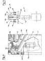
figure 4 is an enlarged view of a portion of the machine offigure 1 ; -
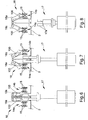
figure 5 is a front view of a portion of the machine offigure 1 , in a first operating stage; -
figure 6 is a front view of the portion of machine offigure 5 , in a second operating stage; -
figure 7 is a front view of the portion of machine offigure 5 , in a third operating stage; -
figure 8 is a front view of the portion of machine offigure 5 , in a fourth operating stage; -
figure 9 is a perspective view of an outlet portion of the machine offigure 1 ; -
figure 10 is a section view of a confectionery product obtained according to the method of the present invention. - In
figure 10 , 100 denotes a confectionery product obtained using the method and the machine of the present invention. - The
confectionery product 100, shown in a section view to include the contents thereof, comprises aconical wafer 101 which, in the illustrated embodiment offigure 9 , is provided with an inlet mouth facing upwards and a point facing downwards. - Internally of the
wafer 101 is a first layer of afirst food product 102 on which a second layer of asecond food product 103 is arranged. By way of example, the first food product is chocolate-based whereas the second is cream-based. Preferably, the two food products are in the liquid or semiliquid state, preferably having a creamy texture. - A coating layer is deposited on the upper surface of the second layer, preferably made of a granulated foodstuff, such as nuts.
- The inlet mouth of the
wafer 101 is closed by acircular lid 105. Thewafer 101 is further externally covered with a covering 106 made of wrapping paper which superiorly exhibits anend flap 107 folded on thelid 105 to block thelid 105 stably on thewafer 101. - In the view of
figure 1, 1 denotes in its entirety a machine for realising theconfectionery product 100 offigure 9 . - The
machine 1 comprises a conveyor device, with might also have a straight development, but preferably comprises acarousel 2 which is rotatable about an axis X and which has a plurality ofsupport seatings 3 for containingwafers 101 with the inlet mouth thereof facing upwards. The rotation axis X of thecarousel 2 is vertical. - The
support seatings 3 are arranged over a whole angular development of thecarousel 2 about the rotation axis X and, in the illustrated embodiment, they are grouped in ten groups each constituted by sixsupport seatings 3. The groups, which are angularly equidistanced about the rotation axis X, are each made up of two rows of threeseatings 3, arranged side by side in a radial direction. - In an anticlockwise direction (rotation direction R), in the view of
figure 1 , themachine 1 comprises: - a pair of
loading stations support seatings 3; - a
first filling station 6 for pouring a batch of thefirst food product 102 into thewafers 101; - a
second filling station 7 for pouring a batch of thesecond food product 103 into thewafers 101; - a
third filling station 8 for pouring a batch of granulated foodstuff (covering layer 104) into thewafers 101; - a
closing station 9 for application of thelid 105 on the filledwafer 101; - a
folding station 10 for folding the above-mentionedupper flaps 107 of the covering 106 on thelid 105; - an
outlet station 11 of thewafers 101 thus completed. - The
carousel 2 is rotatable about the rotation axis X in order to bring thesupport seatings 3 through all the mentioned stations in the above-described order. The above-described stations are well visible infigures 2 and3 . - In embodiments of the invention which are not illustrated, the
third filling station 8 might be omitted, or one of the first twofilling stations third filling station 8 and one of the first twofilling stations 6 7 could be omitted. - The
loading stations - The
filling stations wafer 101 through the inlet mouth of thewafer 101. The filling of thewafer 101 might be partial or complete, according to theconfectionery product 100 to be produced. - In the present invention, the first and the
second food products wafer 101 while in the liquid or semiliquid state, preferably in the creamy state. To realise this, the two food products might need to be heated and therefore to be at above ambient temperature, preferably comprised between 10°C and 60°C. In this case, given the rapidity of the functioning of the machine, the product remains in the liquid state up to when it reaches theoutlet station 11, and even beyond. - The filling
stations - The
closing station 9 comprises amobile support 12, rotatable about ahorizontal axis 12a and vertically slidable onguides 12b. Themobile support 12 is provided with sixunits 12c each of which is positionable at one of the support seatings 3 in order to apply alid 105 onto awafer 101. Themobile support 12 assumes a removal configuration, in which it is arranged at the top of theguides 12b in order to enable theunits 12c (facing upwards) to removerespective lids 105 from a same number of piles P oflids 105, and an application position in which it lowers and turns theunits 12c downwards in order to apply thelids 105 on theunderlying wafers 101. - The following
folding station 10 comprises six pressers 13 which lower towards the underlyingwafers 101 in order to fold theupper flaps 107 of the above-describedcovering 106 of thewafers 101. - A
conveyor 14 is located at theoutlet station 11, which is immediately downstream of thefolding station 10, whichconveyor 14 has the function of conveying thewafers 101 to successive work stations (not illustrated), for example packing or marking stations, or others beside. - In the illustrated embodiment,
figure 9 clearly shows that theconveyor 14 comprises two parallel segments, 14a, 14b, each of which receives and conveys thewafers 101 coming from a respective row of three of each group of sixwafers 101 arranged on thecarousel 2. Theconveyor 14, during the transport of the filledwafers 101, advantageously keeps thewafers 101 in a vertical orientation, i.e. with the inlet mouth facing upwards to prevent exit of thefood products wafers 101 are closed by thelids 105, thefood products wafers 101 be arranged horizontally or in any case in an incorrect position. A wrong positioning of thewafers 101 might also create undesired reciprocal mixing of thefood products granulated foodstuff 104, causing a deterioration of theconfectionery product 100 which would no longer be fit for sale. - As shown in
figures 8 and9 , each filled and packedwafer 101 is supported, while on theconveyor 14, at opposite sides thereof such as to be automatically orientated in a vertical direction under the action of its own weight. To this end, eachsegment parallel bands 15 which face one another and are distanced in order to define ahollow space 16 in which the lower point of theconical wafer 101 inserts. Theparallel bands 15 are mobile in an advancement direction A in order to convey thewafers 101 away from thecarousel 2 while they support thewafers 101 thanks to the fact that the upper part of thewafers 101 has a transversal dimension which is greater than thehollow space 16 and thus rests on the parallel sides 15. The parallel bands are preferably defined by facing parallel branches of two conveyors having parallel belts. - The
machine 1 further comprises means for transfer, arranged at theoutlet station 11 and acting between thecarousel 2 and theconveyor 14 to remove thewafers 101 from thecarousel 2 and deposit them on thetransporter 14. The means for transfer primarily comprise apusher 17 which raises the filled and packedwafers 101 from therespective support seatings 3. Thepusher 17 exhibits sixterminals 17a each of which intercepts the lower portions of thewafers 101 and raised them up until they are disengaged from thesupport seatings 3. Theterminals 17a are thus destined to cross the support seatings 3 in order to realise a total disengagement of thewafers 101 from thesupport seatings 3. - In greater detail, the
pusher 17 is mobile between an inactive position (figures 4, 5 ,8 ) in which it is in a lowered position and enables rotation of thecarousel 2, and a working position (figures 6 and 7 ), in which it is in a raised position in order to disengage thewafers 101 from therespective support seatings 3. - The movement direction of the
pusher 17 is substantially parallel to the rotation axis X of thecarousel 2 and is therefore substantially vertical. - The means for transfer further comprise a
tilter 18 which receives thewafers 101 raised by thepusher 17 and conveys them towards theconveyor 14. As shown in figures from 4 to 8, thetilter 18 comprises six C-shapedcontainer elements 18a provided with an opening facing downwards in order each to receive awafer 101. Eachcontainer element 18a exhibits ahousing 19 in which asingle wafer 101 can be housed. - In more detail, each
container element 18a is rotatable about a preferably horizontal rotation axis between a receiving position (illustrated infigures 5 and6 ), in which it faces anunderlying wafer 101, and a release position in which it turns the lower opening towards theconveyor 14 to release thewafer 101 towards theconveyor 4. - In the receiving position, each
container element 18a is arranged along a first direction, substantially parallel to the raising direction of thewafer 101, such that thepusher 17 pushes thewafer 101 into thehousing 19 of thecontainer element 18. - In the release position, the
container element 18a is arranged in a second inclined direction with respect to the first direction, and in particular turning the lower opening towards theconveyor 14 in order to release thewafer 101 contained in thehousing 19 by force of gravity onto theconveyor 14. - Activation of the
pusher 17 and thetilter 18 is done by means of actuators (not illustrated), preferably hydraulic or pneumatic and possibly involving interposing of mechanical elements (not illustrated). - In embodiments of the invention which are not illustrated herein, the
carousel 2 might exhibit a different number ofsupport seatings 3, for example a single circumferential row of seatings for production of asingle confectionery product 100 at each advancement of thecarousel 2, or might exhibit groups ofsupport seatings 3 having a different number ofsupport seatings 3. In these further embodiments, thepusher 17 and thetilter 18 consequently assume different configurations, and thepusher 17 can comprise one ormore terminals 17a, and thetilter 18 can exhibit one ormore container elements 18a. Consequently asingle segment conveyor 14 can be included. - The present invention attains the set aims, overcoming the drawbacks inherent in the prior art.
- The use of a conveyor enabling the wafers to be orientated vertically by force of gravity (as shown in
figure 9 ) enables production of articles of confectionery containing liquid/semiliquid food products, or products which are entirely melted, which otherwise would be subject to deterioration or leakage of the food products. This is especially referred to cone-shaped confectionery products which are not naturally suited to assuming a vertical position when transported. - The above-described use of means for transfer further enables a rapid and efficient expulsion of the hot wafers from the support seatings of the carousel and the sending-on thereof to the conveyor, without the wafers significantly changing their orientation, thus again preventing deterioration or leakage of the confectionery products contained in the wafers.
Claims (18)
- A method for production of confectionery products, wherein it comprises stages of:predisposing a wafer (101) having an inlet mouth for a food product (102, 103) to be inserted in the wafer (101), the wafer (101) being orientated in such a way as to have the inlet mouth thereof facing in an upwards direction;at least partially filling the wafer (101) through the inlet mouth with a liquid or semiliquid food product (102, 103);packing the filled wafer (101), realising at least a closure of the inlet mouth;conveying the filled and packed wafer (101) to a following work station while the wafer (101) is maintained in a substantially vertical orientation which prevents exit of the liquid or semi-liquid food product (102, 103) from the wafer (101);the stage of conveying being realised contemporaneously to a stage of supporting the wafer (101) on two opposite sides thereof, such that the wafer (101) is kept in the substantially vertical orientation by action of an own weight thereof.
- The method of claim 1, wherein the stage of predisposing the wafer (101) comprises a stage of predisposing a wafer (101) having a conical shape.
- The method of claim 1 or 2, characterised in that the stage of predisposing the wafer (101) is realised by arranging the wafer (101) on a conveyor device (2) having a plurality of support seatings (3) for respective wafers (101), the method further comprising successive stages of activating the conveyor device (2) in order to bring the wafer (101) to at least a filling station (6, 7, 8) and an outlet station (11).
- The method of one or more of the preceding claims, wherein the stage of predisposing the wafer (101) comprises a stage of pre-wrapping the wafer (101) with an external wrapping (106) made of a wrapping paper.
- The method of one or more of the preceding claims, wherein it comprises, between the stage of packing the wafer (101) and the stage of conveying the wafer (101), a stage of removing the wafer (101) from a carousel (2); the stage of removing comprising:a first stage of distancing the wafer (101) from the respective support seating (3) along a first direction which is substantially parallel to the rotation axis (X) of the carousel (2), anda successive second stage of nearing the wafer (101) to a conveyor (14) destined to perform the conveying stage.
- The method of claim 5, wherein the first stage is realised by raising the wafer (101) with respect to the support seating (3) and wherein the second stage of nearing is realised by arranging the wafer (101) in a second inclined direction with respect to the first direction and allowing the wafer (101) to slide by force of gravity along the inclined direction towards a different zone from the support seating (3) in which the wafer (101) was previously housed.
- The method of one or more of the preceding claims, wherein the stage of conveying is realised when the food product (102, 103) contained in the wafer is in a liquid/semiliquid state.
- The method of one or more of the preceding claims, wherein the stage of conveying is realised when the food product (102, 103) contained in the wafer is in a melted state and exhibits a temperature which is above an ambient temperature, preferably comprised between 10°C and 60°C.
- The method of claim 4, wherein the stage of closing the inlet mouth comprises a stage of applying a lid (105) to the inlet mouth and a stage of folding a flap (107) of the external covering (106) on the lid (105) in order to block the lid (105) in a stable position.
- The method of any one of the preceding claims, wherein the stage of predisposing the wafer (101) is realised by arranging the wafer (101) on a rotatable carousel (2) having a plurality of support seatings (3) for respective wafers (101), the method further comprising successive stages of rotating the carousel (2) about the axis (X) in order to bring the wafer (101) to at least a filling station (6, 7, 8) and an outlet station.
- A machine for producing confectionery articles, preferably for realising the method of one of more of the preceding claims, comprising:a conveyor device having a plurality of support seatings (3) for wafers (101) distributed in a predetermined way;at least a loading station (4, 5) of the wafers (101), a filling station (6, 7, 8) of the wafers (101) with a liquid or semiliquid food product (102, 103), and an outlet station (11) for the wafers (101);at least a conveyor (14) for receiving the wafers (101) coming from the outlet station (11) and for conveying the wafers (101) to a successive work station while the wafers (101) are kept in a substantially vertical orientation suitablefor preventing an exit of the food product (102, 103) contained in the wafer (101);means for transferring (17, 18) arranged at the outlet station (11) and acting on the wafers (101) present on a carousel (2) in order to transfer the wafers (101) from the carousel (2) to the conveyor (14).
- The machine of claim 11, wherein the means for transferring (17, 18) comprise a pusher (17), acting on at least a wafer (101) present on the carousel (2) for distancing the wafer (101) from the respective support seating (3) along a first direction, and a tilter (18) acting on the wafer (101) which is distanced from the support seating (3) for conveying the wafer (101) along a second direction, inclined with respect to the first direction, and transferring the wafer (101) onto the conveyor (14).
- The machine of claim 12, wherein the pusher (17) is mobile between an inactive position, in which it is in a lowered position, and a working position, in which it is in a raised position and intercepts a lower portion of a wafer (101), disengaging the wafer (101) from the respective support seating (3).
- The machine of claim 12 or 13, wherein the tilter (18) comprises at least a container element (18a) having a housing (19) in which a wafer (101) can be housed, the container element (18a) being rotatable between a receiving position, in which it is arranged along the first direction to receive a wafer (101) which has been distanced from the respective support seating (3) by action of the pusher, and a release position, in which it is arranged along the second direction in order to release the wafer (101) by force of gravity towards the conveyor (14).
- The machine of claim 14, wherein the container element (18a) is C-shaped and exhibits a receiving opening which faces downwards and faces towards a support seating (3) of the carousel (2) when the container element (18a) is in the receiving position.
- The machine of one or more of claims from 11 to 15, wherein the conveyor (14) exhibits at least a segment (14a, 14b) which comprises two bands (15) which are mobile and parallel in an advancement direction (A) and which define between them a hollow space (16) in which a lower part of the wafer (101) is arranged during transport, the parallel sides (25) supporting an upper part of the wafer (101) on opposite sides thereof during transport of the wafer (101).
- The machine of claim 16, wherein the two parallel sides (15) are defined by facing branches of a pair of parallel-belt conveyors.
- The machine of any one of claims from 11 to 17, wherein the conveyor device comprises a carousel (2) which is rotatable about a rotation axis (X) and which has a plurality of support seatings (3) for wafers (101) which support seatings (3) are angularly distributed about the rotation axis (X).
Priority Applications (1)
| Application Number | Priority Date | Filing Date | Title |
|---|---|---|---|
| PL08790040T PL2317866T3 (en) | 2008-07-04 | 2008-07-04 | Method and device for producing confectionery |
Applications Claiming Priority (1)
| Application Number | Priority Date | Filing Date | Title |
|---|---|---|---|
| PCT/IT2008/000451 WO2010001424A1 (en) | 2008-07-04 | 2008-07-04 | Method and device for producing confectionery |
Publications (2)
| Publication Number | Publication Date |
|---|---|
| EP2317866A1 EP2317866A1 (en) | 2011-05-11 |
| EP2317866B1 true EP2317866B1 (en) | 2012-08-08 |
Family
ID=40427968
Family Applications (1)
| Application Number | Title | Priority Date | Filing Date |
|---|---|---|---|
| EP08790040A Not-in-force EP2317866B1 (en) | 2008-07-04 | 2008-07-04 | Method and device for producing confectionery |
Country Status (5)
| Country | Link |
|---|---|
| EP (1) | EP2317866B1 (en) |
| ES (1) | ES2392703T3 (en) |
| PL (1) | PL2317866T3 (en) |
| PT (1) | PT2317866E (en) |
| WO (1) | WO2010001424A1 (en) |
Families Citing this family (3)
| Publication number | Priority date | Publication date | Assignee | Title |
|---|---|---|---|---|
| US20250197910A1 (en) | 2022-03-24 | 2025-06-19 | Danisco Us Inc. | Compositions and methods for industrial scale production and recovery of lectins |
| CN119997966A (en) | 2022-09-20 | 2025-05-13 | 国际N&H丹麦有限公司 | Variant antiviral peptides |
| WO2025007098A1 (en) | 2023-06-30 | 2025-01-02 | Danisco Us Inc. | Recombinant fungal cells and methods thereof for industrial scale production of lectins |
Family Cites Families (9)
| Publication number | Priority date | Publication date | Assignee | Title |
|---|---|---|---|---|
| US2366941A (en) * | 1942-03-14 | 1945-01-09 | Cream Cone Machine Company | Confection handling apparatus |
| US3092944A (en) * | 1957-09-03 | 1963-06-11 | Big Drum Inc | Apparatus for forming an edible article and a packaged article produced thereby |
| US3070933A (en) | 1959-05-26 | 1963-01-01 | Universal Machine Co Inc | Machine for manufacturing novelty ice cream products |
| US3025983A (en) | 1959-06-10 | 1962-03-20 | Loft Candy Corp | Tray for conveying candy |
| US3478702A (en) * | 1967-01-07 | 1969-11-18 | Mario Simonich | Machine for drawing,filling with a bulk material and automatically distributing a container |
| US4942910A (en) | 1986-11-07 | 1990-07-24 | Fantasy Flavors Inc. | Process and apparatus for making shaped confections |
| IT1264571B1 (en) * | 1993-06-10 | 1996-10-04 | Universal Ice Cream Machines S | AUTOMATIC MACHINE FOR THE DISTRIBUTION OF A PORTION OF ICE CREAM |
| ITMI981210A1 (en) * | 1998-06-01 | 1999-12-01 | Sidam Srl | PROCEDURE FOR THE PRODUCTION OF ICE CREAM IN CONES AND RELATED PRODUCT |
| US6355290B1 (en) * | 1998-07-17 | 2002-03-12 | Creative Edge Design Group, Ltd. | Ice cream manufacturing and packaging process and a package for this process |
-
2008
- 2008-07-04 ES ES08790040T patent/ES2392703T3/en active Active
- 2008-07-04 EP EP08790040A patent/EP2317866B1/en not_active Not-in-force
- 2008-07-04 PT PT08790040T patent/PT2317866E/en unknown
- 2008-07-04 WO PCT/IT2008/000451 patent/WO2010001424A1/en not_active Ceased
- 2008-07-04 PL PL08790040T patent/PL2317866T3/en unknown
Also Published As
| Publication number | Publication date |
|---|---|
| WO2010001424A1 (en) | 2010-01-07 |
| PT2317866E (en) | 2012-11-15 |
| PL2317866T3 (en) | 2013-01-31 |
| ES2392703T3 (en) | 2012-12-13 |
| EP2317866A1 (en) | 2011-05-11 |
Similar Documents
| Publication | Publication Date | Title |
|---|---|---|
| US4942910A (en) | Process and apparatus for making shaped confections | |
| CN101484020A (en) | Versatile enhanced production line for preparing and packaging food products | |
| US4427703A (en) | Confectionery articles, and apparatus and processes for producing them | |
| KR101494253B1 (en) | Apparatus for supplying stick type biscuits | |
| NZ208226A (en) | Measuring, shaping and packaging multi-layer portions of spreadable food products | |
| JPH05506146A (en) | Automatic food dispensing device | |
| US5918765A (en) | Container dispensing systems especially useful for dispensing edible cones | |
| WO2002015706A2 (en) | A frozen confectionery product and method of manufacture | |
| US3809774A (en) | Loading process for ice cream carrier strip | |
| US20100256797A1 (en) | Machine for making pods containing infusion products | |
| EP2317866A1 (en) | Method and device for producing confectionery | |
| US2598137A (en) | Method of packaging and serving frozen confections | |
| US5322432A (en) | Apparatus for making frozen edible products | |
| US8572934B2 (en) | Food portioning system | |
| US20240217684A1 (en) | Apparatus and method for packaging products in boxes | |
| US20230202775A1 (en) | Transfer device, particularly for a packing machine | |
| US7134386B2 (en) | Automatic bottom-filling injection system | |
| RU2731066C2 (en) | Unit for filling portion reservoirs with food product | |
| JP2002142682A (en) | Method for producing ice cream with surface decoration | |
| GB2084445A (en) | Processes and apparatus for producing confectionery articles | |
| EP2050675B1 (en) | Process for the preparation of a folded pouch for cooking food in paper wrap | |
| CN110996676A (en) | Ways to Fill Containers with Frozen Sweets | |
| KR20050011268A (en) | Method of automatic packaging for ice-cream cone cake and device thereof | |
| US20210368822A1 (en) | System for producing and manufacturing of frozen confection product and method thereof | |
| GB2084448A (en) | Composite ice confections |
Legal Events
| Date | Code | Title | Description |
|---|---|---|---|
| PUAI | Public reference made under article 153(3) epc to a published international application that has entered the european phase |
Free format text: ORIGINAL CODE: 0009012 |
|
| 17P | Request for examination filed |
Effective date: 20101221 |
|
| AK | Designated contracting states |
Kind code of ref document: A1 Designated state(s): AT BE BG CH CY CZ DE DK EE ES FI FR GB GR HR HU IE IS IT LI LT LU LV MC MT NL NO PL PT RO SE SI SK TR |
|
| AX | Request for extension of the european patent |
Extension state: AL BA MK RS |
|
| DAX | Request for extension of the european patent (deleted) | ||
| GRAP | Despatch of communication of intention to grant a patent |
Free format text: ORIGINAL CODE: EPIDOSNIGR1 |
|
| GRAS | Grant fee paid |
Free format text: ORIGINAL CODE: EPIDOSNIGR3 |
|
| RIN1 | Information on inventor provided before grant (corrected) |
Inventor name: MESSORI, MASSIMO |
|
| GRAA | (expected) grant |
Free format text: ORIGINAL CODE: 0009210 |
|
| AK | Designated contracting states |
Kind code of ref document: B1 Designated state(s): AT BE BG CH CY CZ DE DK EE ES FI FR GB GR HR HU IE IS IT LI LT LU LV MC MT NL NO PL PT RO SE SI SK TR |
|
| REG | Reference to a national code |
Ref country code: GB Ref legal event code: FG4D |
|
| REG | Reference to a national code |
Ref country code: AT Ref legal event code: REF Ref document number: 569253 Country of ref document: AT Kind code of ref document: T Effective date: 20120815 Ref country code: CH Ref legal event code: EP |
|
| REG | Reference to a national code |
Ref country code: IE Ref legal event code: FG4D |
|
| REG | Reference to a national code |
Ref country code: DE Ref legal event code: R096 Ref document number: 602008017857 Country of ref document: DE Effective date: 20121004 |
|
| REG | Reference to a national code |
Ref country code: PT Ref legal event code: SC4A Free format text: AVAILABILITY OF NATIONAL TRANSLATION Effective date: 20121102 |
|
| REG | Reference to a national code |
Ref country code: NL Ref legal event code: T3 |
|
| REG | Reference to a national code |
Ref country code: ES Ref legal event code: FG2A Ref document number: 2392703 Country of ref document: ES Kind code of ref document: T3 Effective date: 20121213 |
|
| REG | Reference to a national code |
Ref country code: AT Ref legal event code: MK05 Ref document number: 569253 Country of ref document: AT Kind code of ref document: T Effective date: 20120808 |
|
| REG | Reference to a national code |
Ref country code: LT Ref legal event code: MG4D Effective date: 20120808 |
|
| PG25 | Lapsed in a contracting state [announced via postgrant information from national office to epo] |
Ref country code: NO Free format text: LAPSE BECAUSE OF FAILURE TO SUBMIT A TRANSLATION OF THE DESCRIPTION OR TO PAY THE FEE WITHIN THE PRESCRIBED TIME-LIMIT Effective date: 20121108 Ref country code: AT Free format text: LAPSE BECAUSE OF FAILURE TO SUBMIT A TRANSLATION OF THE DESCRIPTION OR TO PAY THE FEE WITHIN THE PRESCRIBED TIME-LIMIT Effective date: 20120808 Ref country code: FI Free format text: LAPSE BECAUSE OF FAILURE TO SUBMIT A TRANSLATION OF THE DESCRIPTION OR TO PAY THE FEE WITHIN THE PRESCRIBED TIME-LIMIT Effective date: 20120808 Ref country code: CY Free format text: LAPSE BECAUSE OF FAILURE TO SUBMIT A TRANSLATION OF THE DESCRIPTION OR TO PAY THE FEE WITHIN THE PRESCRIBED TIME-LIMIT Effective date: 20120808 Ref country code: HR Free format text: LAPSE BECAUSE OF FAILURE TO SUBMIT A TRANSLATION OF THE DESCRIPTION OR TO PAY THE FEE WITHIN THE PRESCRIBED TIME-LIMIT Effective date: 20120808 Ref country code: LT Free format text: LAPSE BECAUSE OF FAILURE TO SUBMIT A TRANSLATION OF THE DESCRIPTION OR TO PAY THE FEE WITHIN THE PRESCRIBED TIME-LIMIT Effective date: 20120808 Ref country code: IS Free format text: LAPSE BECAUSE OF FAILURE TO SUBMIT A TRANSLATION OF THE DESCRIPTION OR TO PAY THE FEE WITHIN THE PRESCRIBED TIME-LIMIT Effective date: 20121208 |
|
| REG | Reference to a national code |
Ref country code: PL Ref legal event code: T3 |
|
| PG25 | Lapsed in a contracting state [announced via postgrant information from national office to epo] |
Ref country code: SI Free format text: LAPSE BECAUSE OF FAILURE TO SUBMIT A TRANSLATION OF THE DESCRIPTION OR TO PAY THE FEE WITHIN THE PRESCRIBED TIME-LIMIT Effective date: 20120808 Ref country code: SE Free format text: LAPSE BECAUSE OF FAILURE TO SUBMIT A TRANSLATION OF THE DESCRIPTION OR TO PAY THE FEE WITHIN THE PRESCRIBED TIME-LIMIT Effective date: 20120808 Ref country code: GR Free format text: LAPSE BECAUSE OF FAILURE TO SUBMIT A TRANSLATION OF THE DESCRIPTION OR TO PAY THE FEE WITHIN THE PRESCRIBED TIME-LIMIT Effective date: 20121109 Ref country code: LV Free format text: LAPSE BECAUSE OF FAILURE TO SUBMIT A TRANSLATION OF THE DESCRIPTION OR TO PAY THE FEE WITHIN THE PRESCRIBED TIME-LIMIT Effective date: 20120808 |
|
| PG25 | Lapsed in a contracting state [announced via postgrant information from national office to epo] |
Ref country code: DK Free format text: LAPSE BECAUSE OF FAILURE TO SUBMIT A TRANSLATION OF THE DESCRIPTION OR TO PAY THE FEE WITHIN THE PRESCRIBED TIME-LIMIT Effective date: 20120808 Ref country code: CZ Free format text: LAPSE BECAUSE OF FAILURE TO SUBMIT A TRANSLATION OF THE DESCRIPTION OR TO PAY THE FEE WITHIN THE PRESCRIBED TIME-LIMIT Effective date: 20120808 Ref country code: RO Free format text: LAPSE BECAUSE OF FAILURE TO SUBMIT A TRANSLATION OF THE DESCRIPTION OR TO PAY THE FEE WITHIN THE PRESCRIBED TIME-LIMIT Effective date: 20120808 Ref country code: EE Free format text: LAPSE BECAUSE OF FAILURE TO SUBMIT A TRANSLATION OF THE DESCRIPTION OR TO PAY THE FEE WITHIN THE PRESCRIBED TIME-LIMIT Effective date: 20120808 |
|
| PLBI | Opposition filed |
Free format text: ORIGINAL CODE: 0009260 |
|
| PLAB | Opposition data, opponent's data or that of the opponent's representative modified |
Free format text: ORIGINAL CODE: 0009299OPPO |
|
| PG25 | Lapsed in a contracting state [announced via postgrant information from national office to epo] |
Ref country code: SK Free format text: LAPSE BECAUSE OF FAILURE TO SUBMIT A TRANSLATION OF THE DESCRIPTION OR TO PAY THE FEE WITHIN THE PRESCRIBED TIME-LIMIT Effective date: 20120808 |
|
| PLAX | Notice of opposition and request to file observation + time limit sent |
Free format text: ORIGINAL CODE: EPIDOSNOBS2 |
|
| 26 | Opposition filed |
Opponent name: UNILEVER PLC Effective date: 20130507 |
|
| R26 | Opposition filed (corrected) |
Opponent name: UNILEVER PLC/ UNILEVER N.V. Effective date: 20130507 |
|
| PG25 | Lapsed in a contracting state [announced via postgrant information from national office to epo] |
Ref country code: BG Free format text: LAPSE BECAUSE OF FAILURE TO SUBMIT A TRANSLATION OF THE DESCRIPTION OR TO PAY THE FEE WITHIN THE PRESCRIBED TIME-LIMIT Effective date: 20121108 |
|
| REG | Reference to a national code |
Ref country code: DE Ref legal event code: R026 Ref document number: 602008017857 Country of ref document: DE Effective date: 20130507 |
|
| REG | Reference to a national code |
Ref country code: HU Ref legal event code: AG4A Ref document number: E016428 Country of ref document: HU |
|
| PLAF | Information modified related to communication of a notice of opposition and request to file observations + time limit |
Free format text: ORIGINAL CODE: EPIDOSCOBS2 |
|
| PLBP | Opposition withdrawn |
Free format text: ORIGINAL CODE: 0009264 |
|
| PLBB | Reply of patent proprietor to notice(s) of opposition received |
Free format text: ORIGINAL CODE: EPIDOSNOBS3 |
|
| PLAU | Termination of opposition procedure: information related to despatch of decision deleted |
Free format text: ORIGINAL CODE: EPIDOSDOPC1 |
|
| PLBD | Termination of opposition procedure: decision despatched |
Free format text: ORIGINAL CODE: EPIDOSNOPC1 |
|
| PG25 | Lapsed in a contracting state [announced via postgrant information from national office to epo] |
Ref country code: MC Free format text: LAPSE BECAUSE OF FAILURE TO SUBMIT A TRANSLATION OF THE DESCRIPTION OR TO PAY THE FEE WITHIN THE PRESCRIBED TIME-LIMIT Effective date: 20120808 |
|
| REG | Reference to a national code |
Ref country code: CH Ref legal event code: PL |
|
| PLBM | Termination of opposition procedure: date of legal effect published |
Free format text: ORIGINAL CODE: 0009276 |
|
| STAA | Information on the status of an ep patent application or granted ep patent |
Free format text: STATUS: OPPOSITION PROCEDURE CLOSED |
|
| REG | Reference to a national code |
Ref country code: PT Ref legal event code: MM4A Free format text: LAPSE DUE TO NON-PAYMENT OF FEES Effective date: 20140404 |
|
| REG | Reference to a national code |
Ref country code: IE Ref legal event code: MM4A |
|
| 27C | Opposition proceedings terminated |
Effective date: 20140127 |
|
| PG25 | Lapsed in a contracting state [announced via postgrant information from national office to epo] |
Ref country code: HU Free format text: LAPSE BECAUSE OF NON-PAYMENT OF DUE FEES Effective date: 20130705 Ref country code: LI Free format text: LAPSE BECAUSE OF NON-PAYMENT OF DUE FEES Effective date: 20130731 Ref country code: CH Free format text: LAPSE BECAUSE OF NON-PAYMENT OF DUE FEES Effective date: 20130731 |
|
| PG25 | Lapsed in a contracting state [announced via postgrant information from national office to epo] |
Ref country code: IE Free format text: LAPSE BECAUSE OF NON-PAYMENT OF DUE FEES Effective date: 20130704 |
|
| PG25 | Lapsed in a contracting state [announced via postgrant information from national office to epo] |
Ref country code: PT Free format text: LAPSE BECAUSE OF NON-PAYMENT OF DUE FEES Effective date: 20140404 |
|
| PGFP | Annual fee paid to national office [announced via postgrant information from national office to epo] |
Ref country code: TR Payment date: 20140620 Year of fee payment: 7 |
|
| REG | Reference to a national code |
Ref country code: ES Ref legal event code: FD2A Effective date: 20141010 |
|
| PGFP | Annual fee paid to national office [announced via postgrant information from national office to epo] |
Ref country code: NL Payment date: 20140726 Year of fee payment: 7 Ref country code: DE Payment date: 20140729 Year of fee payment: 7 |
|
| REG | Reference to a national code |
Ref country code: PL Ref legal event code: LAPE |
|
| PG25 | Lapsed in a contracting state [announced via postgrant information from national office to epo] |
Ref country code: PL Free format text: LAPSE BECAUSE OF NON-PAYMENT OF DUE FEES Effective date: 20130704 |
|
| PGFP | Annual fee paid to national office [announced via postgrant information from national office to epo] |
Ref country code: GB Payment date: 20140729 Year of fee payment: 7 Ref country code: FR Payment date: 20140717 Year of fee payment: 7 |
|
| PG25 | Lapsed in a contracting state [announced via postgrant information from national office to epo] |
Ref country code: ES Free format text: LAPSE BECAUSE OF NON-PAYMENT OF DUE FEES Effective date: 20130705 |
|
| PGFP | Annual fee paid to national office [announced via postgrant information from national office to epo] |
Ref country code: BE Payment date: 20140730 Year of fee payment: 7 |
|
| PG25 | Lapsed in a contracting state [announced via postgrant information from national office to epo] |
Ref country code: MT Free format text: LAPSE BECAUSE OF FAILURE TO SUBMIT A TRANSLATION OF THE DESCRIPTION OR TO PAY THE FEE WITHIN THE PRESCRIBED TIME-LIMIT Effective date: 20120808 |
|
| PG25 | Lapsed in a contracting state [announced via postgrant information from national office to epo] |
Ref country code: LU Free format text: LAPSE BECAUSE OF NON-PAYMENT OF DUE FEES Effective date: 20130704 |
|
| REG | Reference to a national code |
Ref country code: DE Ref legal event code: R119 Ref document number: 602008017857 Country of ref document: DE |
|
| GBPC | Gb: european patent ceased through non-payment of renewal fee |
Effective date: 20150704 |
|
| REG | Reference to a national code |
Ref country code: NL Ref legal event code: MM Effective date: 20150801 |
|
| PG25 | Lapsed in a contracting state [announced via postgrant information from national office to epo] |
Ref country code: DE Free format text: LAPSE BECAUSE OF NON-PAYMENT OF DUE FEES Effective date: 20160202 Ref country code: GB Free format text: LAPSE BECAUSE OF NON-PAYMENT OF DUE FEES Effective date: 20150704 |
|
| REG | Reference to a national code |
Ref country code: FR Ref legal event code: ST Effective date: 20160331 |
|
| PG25 | Lapsed in a contracting state [announced via postgrant information from national office to epo] |
Ref country code: NL Free format text: LAPSE BECAUSE OF NON-PAYMENT OF DUE FEES Effective date: 20150801 Ref country code: FR Free format text: LAPSE BECAUSE OF NON-PAYMENT OF DUE FEES Effective date: 20150731 |
|
| PGFP | Annual fee paid to national office [announced via postgrant information from national office to epo] |
Ref country code: IT Payment date: 20160727 Year of fee payment: 9 |
|
| PG25 | Lapsed in a contracting state [announced via postgrant information from national office to epo] |
Ref country code: BE Free format text: LAPSE BECAUSE OF NON-PAYMENT OF DUE FEES Effective date: 20150731 |
|
| PG25 | Lapsed in a contracting state [announced via postgrant information from national office to epo] |
Ref country code: TR Free format text: LAPSE BECAUSE OF NON-PAYMENT OF DUE FEES Effective date: 20150704 |
|
| PG25 | Lapsed in a contracting state [announced via postgrant information from national office to epo] |
Ref country code: IT Free format text: LAPSE BECAUSE OF NON-PAYMENT OF DUE FEES Effective date: 20170704 |