EP2317089A2 - Exhaust system - Google Patents
Exhaust system Download PDFInfo
- Publication number
- EP2317089A2 EP2317089A2 EP10168510A EP10168510A EP2317089A2 EP 2317089 A2 EP2317089 A2 EP 2317089A2 EP 10168510 A EP10168510 A EP 10168510A EP 10168510 A EP10168510 A EP 10168510A EP 2317089 A2 EP2317089 A2 EP 2317089A2
- Authority
- EP
- European Patent Office
- Prior art keywords
- predetermined value
- fuel
- nitrogen oxide
- larger
- catalyst
- Prior art date
- Legal status (The legal status is an assumption and is not a legal conclusion. Google has not performed a legal analysis and makes no representation as to the accuracy of the status listed.)
- Granted
Links
Images


Classifications
-
- F—MECHANICAL ENGINEERING; LIGHTING; HEATING; WEAPONS; BLASTING
- F01—MACHINES OR ENGINES IN GENERAL; ENGINE PLANTS IN GENERAL; STEAM ENGINES
- F01N—GAS-FLOW SILENCERS OR EXHAUST APPARATUS FOR MACHINES OR ENGINES IN GENERAL; GAS-FLOW SILENCERS OR EXHAUST APPARATUS FOR INTERNAL-COMBUSTION ENGINES
- F01N9/00—Electrical control of exhaust gas treating apparatus
- F01N9/002—Electrical control of exhaust gas treating apparatus of filter regeneration
-
- F—MECHANICAL ENGINEERING; LIGHTING; HEATING; WEAPONS; BLASTING
- F01—MACHINES OR ENGINES IN GENERAL; ENGINE PLANTS IN GENERAL; STEAM ENGINES
- F01N—GAS-FLOW SILENCERS OR EXHAUST APPARATUS FOR MACHINES OR ENGINES IN GENERAL; GAS-FLOW SILENCERS OR EXHAUST APPARATUS FOR INTERNAL-COMBUSTION ENGINES
- F01N3/00—Exhaust or silencing apparatus having means for purifying, rendering innocuous, or otherwise treating exhaust
- F01N3/08—Exhaust or silencing apparatus having means for purifying, rendering innocuous, or otherwise treating exhaust for rendering innocuous
- F01N3/10—Exhaust or silencing apparatus having means for purifying, rendering innocuous, or otherwise treating exhaust for rendering innocuous by thermal or catalytic conversion of noxious components of exhaust
- F01N3/18—Exhaust or silencing apparatus having means for purifying, rendering innocuous, or otherwise treating exhaust for rendering innocuous by thermal or catalytic conversion of noxious components of exhaust characterised by methods of operation; Control
-
- F—MECHANICAL ENGINEERING; LIGHTING; HEATING; WEAPONS; BLASTING
- F01—MACHINES OR ENGINES IN GENERAL; ENGINE PLANTS IN GENERAL; STEAM ENGINES
- F01N—GAS-FLOW SILENCERS OR EXHAUST APPARATUS FOR MACHINES OR ENGINES IN GENERAL; GAS-FLOW SILENCERS OR EXHAUST APPARATUS FOR INTERNAL-COMBUSTION ENGINES
- F01N11/00—Monitoring or diagnostic devices for exhaust-gas treatment apparatus
-
- F—MECHANICAL ENGINEERING; LIGHTING; HEATING; WEAPONS; BLASTING
- F01—MACHINES OR ENGINES IN GENERAL; ENGINE PLANTS IN GENERAL; STEAM ENGINES
- F01N—GAS-FLOW SILENCERS OR EXHAUST APPARATUS FOR MACHINES OR ENGINES IN GENERAL; GAS-FLOW SILENCERS OR EXHAUST APPARATUS FOR INTERNAL-COMBUSTION ENGINES
- F01N13/00—Exhaust or silencing apparatus characterised by constructional features
- F01N13/009—Exhaust or silencing apparatus characterised by constructional features having two or more separate purifying devices arranged in series
-
- F—MECHANICAL ENGINEERING; LIGHTING; HEATING; WEAPONS; BLASTING
- F01—MACHINES OR ENGINES IN GENERAL; ENGINE PLANTS IN GENERAL; STEAM ENGINES
- F01N—GAS-FLOW SILENCERS OR EXHAUST APPARATUS FOR MACHINES OR ENGINES IN GENERAL; GAS-FLOW SILENCERS OR EXHAUST APPARATUS FOR INTERNAL-COMBUSTION ENGINES
- F01N3/00—Exhaust or silencing apparatus having means for purifying, rendering innocuous, or otherwise treating exhaust
- F01N3/02—Exhaust or silencing apparatus having means for purifying, rendering innocuous, or otherwise treating exhaust for cooling, or for removing solid constituents of, exhaust
- F01N3/021—Exhaust or silencing apparatus having means for purifying, rendering innocuous, or otherwise treating exhaust for cooling, or for removing solid constituents of, exhaust by means of filters
- F01N3/023—Exhaust or silencing apparatus having means for purifying, rendering innocuous, or otherwise treating exhaust for cooling, or for removing solid constituents of, exhaust by means of filters using means for regenerating the filters, e.g. by burning trapped particles
-
- F—MECHANICAL ENGINEERING; LIGHTING; HEATING; WEAPONS; BLASTING
- F01—MACHINES OR ENGINES IN GENERAL; ENGINE PLANTS IN GENERAL; STEAM ENGINES
- F01N—GAS-FLOW SILENCERS OR EXHAUST APPARATUS FOR MACHINES OR ENGINES IN GENERAL; GAS-FLOW SILENCERS OR EXHAUST APPARATUS FOR INTERNAL-COMBUSTION ENGINES
- F01N3/00—Exhaust or silencing apparatus having means for purifying, rendering innocuous, or otherwise treating exhaust
- F01N3/08—Exhaust or silencing apparatus having means for purifying, rendering innocuous, or otherwise treating exhaust for rendering innocuous
- F01N3/10—Exhaust or silencing apparatus having means for purifying, rendering innocuous, or otherwise treating exhaust for rendering innocuous by thermal or catalytic conversion of noxious components of exhaust
- F01N3/105—General auxiliary catalysts, e.g. upstream or downstream of the main catalyst
- F01N3/106—Auxiliary oxidation catalysts
-
- F—MECHANICAL ENGINEERING; LIGHTING; HEATING; WEAPONS; BLASTING
- F01—MACHINES OR ENGINES IN GENERAL; ENGINE PLANTS IN GENERAL; STEAM ENGINES
- F01N—GAS-FLOW SILENCERS OR EXHAUST APPARATUS FOR MACHINES OR ENGINES IN GENERAL; GAS-FLOW SILENCERS OR EXHAUST APPARATUS FOR INTERNAL-COMBUSTION ENGINES
- F01N9/00—Electrical control of exhaust gas treating apparatus
-
- F—MECHANICAL ENGINEERING; LIGHTING; HEATING; WEAPONS; BLASTING
- F02—COMBUSTION ENGINES; HOT-GAS OR COMBUSTION-PRODUCT ENGINE PLANTS
- F02D—CONTROLLING COMBUSTION ENGINES
- F02D41/00—Electrical control of supply of combustible mixture or its constituents
- F02D41/02—Circuit arrangements for generating control signals
- F02D41/021—Introducing corrections for particular conditions exterior to the engine
- F02D41/0235—Introducing corrections for particular conditions exterior to the engine in relation with the state of the exhaust gas treating apparatus
- F02D41/027—Introducing corrections for particular conditions exterior to the engine in relation with the state of the exhaust gas treating apparatus to purge or regenerate the exhaust gas treating apparatus
- F02D41/0275—Introducing corrections for particular conditions exterior to the engine in relation with the state of the exhaust gas treating apparatus to purge or regenerate the exhaust gas treating apparatus the exhaust gas treating apparatus being a NOx trap or adsorbent
-
- F—MECHANICAL ENGINEERING; LIGHTING; HEATING; WEAPONS; BLASTING
- F02—COMBUSTION ENGINES; HOT-GAS OR COMBUSTION-PRODUCT ENGINE PLANTS
- F02D—CONTROLLING COMBUSTION ENGINES
- F02D41/00—Electrical control of supply of combustible mixture or its constituents
- F02D41/02—Circuit arrangements for generating control signals
- F02D41/021—Introducing corrections for particular conditions exterior to the engine
- F02D41/0235—Introducing corrections for particular conditions exterior to the engine in relation with the state of the exhaust gas treating apparatus
- F02D41/027—Introducing corrections for particular conditions exterior to the engine in relation with the state of the exhaust gas treating apparatus to purge or regenerate the exhaust gas treating apparatus
- F02D41/029—Introducing corrections for particular conditions exterior to the engine in relation with the state of the exhaust gas treating apparatus to purge or regenerate the exhaust gas treating apparatus the exhaust gas treating apparatus being a particulate filter
-
- F—MECHANICAL ENGINEERING; LIGHTING; HEATING; WEAPONS; BLASTING
- F02—COMBUSTION ENGINES; HOT-GAS OR COMBUSTION-PRODUCT ENGINE PLANTS
- F02D—CONTROLLING COMBUSTION ENGINES
- F02D41/00—Electrical control of supply of combustible mixture or its constituents
- F02D41/02—Circuit arrangements for generating control signals
- F02D41/14—Introducing closed-loop corrections
- F02D41/1438—Introducing closed-loop corrections using means for determining characteristics of the combustion gases; Sensors therefor
- F02D41/1439—Introducing closed-loop corrections using means for determining characteristics of the combustion gases; Sensors therefor characterised by the position of the sensor
- F02D41/1441—Plural sensors
-
- F—MECHANICAL ENGINEERING; LIGHTING; HEATING; WEAPONS; BLASTING
- F02—COMBUSTION ENGINES; HOT-GAS OR COMBUSTION-PRODUCT ENGINE PLANTS
- F02D—CONTROLLING COMBUSTION ENGINES
- F02D41/00—Electrical control of supply of combustible mixture or its constituents
- F02D41/02—Circuit arrangements for generating control signals
- F02D41/14—Introducing closed-loop corrections
- F02D41/1438—Introducing closed-loop corrections using means for determining characteristics of the combustion gases; Sensors therefor
- F02D41/1444—Introducing closed-loop corrections using means for determining characteristics of the combustion gases; Sensors therefor characterised by the characteristics of the combustion gases
- F02D41/1446—Introducing closed-loop corrections using means for determining characteristics of the combustion gases; Sensors therefor characterised by the characteristics of the combustion gases the characteristics being exhaust temperatures
-
- F—MECHANICAL ENGINEERING; LIGHTING; HEATING; WEAPONS; BLASTING
- F01—MACHINES OR ENGINES IN GENERAL; ENGINE PLANTS IN GENERAL; STEAM ENGINES
- F01N—GAS-FLOW SILENCERS OR EXHAUST APPARATUS FOR MACHINES OR ENGINES IN GENERAL; GAS-FLOW SILENCERS OR EXHAUST APPARATUS FOR INTERNAL-COMBUSTION ENGINES
- F01N2550/00—Monitoring or diagnosing the deterioration of exhaust systems
- F01N2550/02—Catalytic activity of catalytic converters
-
- F—MECHANICAL ENGINEERING; LIGHTING; HEATING; WEAPONS; BLASTING
- F01—MACHINES OR ENGINES IN GENERAL; ENGINE PLANTS IN GENERAL; STEAM ENGINES
- F01N—GAS-FLOW SILENCERS OR EXHAUST APPARATUS FOR MACHINES OR ENGINES IN GENERAL; GAS-FLOW SILENCERS OR EXHAUST APPARATUS FOR INTERNAL-COMBUSTION ENGINES
- F01N2570/00—Exhaust treating apparatus eliminating, absorbing or adsorbing specific elements or compounds
- F01N2570/14—Nitrogen oxides
-
- F—MECHANICAL ENGINEERING; LIGHTING; HEATING; WEAPONS; BLASTING
- F01—MACHINES OR ENGINES IN GENERAL; ENGINE PLANTS IN GENERAL; STEAM ENGINES
- F01N—GAS-FLOW SILENCERS OR EXHAUST APPARATUS FOR MACHINES OR ENGINES IN GENERAL; GAS-FLOW SILENCERS OR EXHAUST APPARATUS FOR INTERNAL-COMBUSTION ENGINES
- F01N2610/00—Adding substances to exhaust gases
- F01N2610/03—Adding substances to exhaust gases the substance being hydrocarbons, e.g. engine fuel
-
- F—MECHANICAL ENGINEERING; LIGHTING; HEATING; WEAPONS; BLASTING
- F02—COMBUSTION ENGINES; HOT-GAS OR COMBUSTION-PRODUCT ENGINE PLANTS
- F02D—CONTROLLING COMBUSTION ENGINES
- F02D41/00—Electrical control of supply of combustible mixture or its constituents
- F02D41/02—Circuit arrangements for generating control signals
- F02D41/021—Introducing corrections for particular conditions exterior to the engine
- F02D41/0235—Introducing corrections for particular conditions exterior to the engine in relation with the state of the exhaust gas treating apparatus
- F02D2041/0265—Introducing corrections for particular conditions exterior to the engine in relation with the state of the exhaust gas treating apparatus to decrease temperature of the exhaust gas treating apparatus
-
- F—MECHANICAL ENGINEERING; LIGHTING; HEATING; WEAPONS; BLASTING
- F02—COMBUSTION ENGINES; HOT-GAS OR COMBUSTION-PRODUCT ENGINE PLANTS
- F02D—CONTROLLING COMBUSTION ENGINES
- F02D2200/00—Input parameters for engine control
- F02D2200/02—Input parameters for engine control the parameters being related to the engine
- F02D2200/08—Exhaust gas treatment apparatus parameters
- F02D2200/0802—Temperature of the exhaust gas treatment apparatus
-
- Y—GENERAL TAGGING OF NEW TECHNOLOGICAL DEVELOPMENTS; GENERAL TAGGING OF CROSS-SECTIONAL TECHNOLOGIES SPANNING OVER SEVERAL SECTIONS OF THE IPC; TECHNICAL SUBJECTS COVERED BY FORMER USPC CROSS-REFERENCE ART COLLECTIONS [XRACs] AND DIGESTS
- Y02—TECHNOLOGIES OR APPLICATIONS FOR MITIGATION OR ADAPTATION AGAINST CLIMATE CHANGE
- Y02A—TECHNOLOGIES FOR ADAPTATION TO CLIMATE CHANGE
- Y02A50/00—TECHNOLOGIES FOR ADAPTATION TO CLIMATE CHANGE in human health protection, e.g. against extreme weather
- Y02A50/20—Air quality improvement or preservation, e.g. vehicle emission control or emission reduction by using catalytic converters
-
- Y—GENERAL TAGGING OF NEW TECHNOLOGICAL DEVELOPMENTS; GENERAL TAGGING OF CROSS-SECTIONAL TECHNOLOGIES SPANNING OVER SEVERAL SECTIONS OF THE IPC; TECHNICAL SUBJECTS COVERED BY FORMER USPC CROSS-REFERENCE ART COLLECTIONS [XRACs] AND DIGESTS
- Y02—TECHNOLOGIES OR APPLICATIONS FOR MITIGATION OR ADAPTATION AGAINST CLIMATE CHANGE
- Y02T—CLIMATE CHANGE MITIGATION TECHNOLOGIES RELATED TO TRANSPORTATION
- Y02T10/00—Road transport of goods or passengers
- Y02T10/10—Internal combustion engine [ICE] based vehicles
- Y02T10/40—Engine management systems
Definitions
- the present invention relates to an exhaust system. More particularly, the present invention relates to an exhaust system that traps particulate materials included in the exhaust gas, and eliminates the trapped particulate materials in a predetermined condition.
- exhaust gas that is exhausted through an exhaust manifold of an engine is induced to pass through a catalytic converter that is mounted in the middle of an exhaust pipe to be purified, and the noise thereof is reduced while passing through a muffler before the exhaust gas is discharged to the outside through a tail pipe.
- the catalytic converter processes the pollution materials that are included in the exhaust gas. Further, a particulate filter is mounted on the exhaust pipe to trap particulate material (PM) that is included in the exhaust gas.
- PM particulate material
- a selective catalytic reduction device is a type of catalytic converter. Reducing agents such as carbon monoxide, total hydrocarbon (THC), and so on react well with nitrogen oxide rather than oxygen in the selective catalyst reduction apparatus (SCR), which is why it is called a selective catalyst reduction apparatus (SCR).
- SCR selective catalyst reduction apparatus
- the fuel is continuously and additionally injected according to the nitrogen oxide amount in the exhaust gas. Accordingly, the hydrocarbon can be slipped from the selective catalyst reduction apparatus, and the fuel consumption is increased.
- Various aspects of the present invention are directed to provide an exhaust system having advantages of varying a regeneration temperature depending on the degradation rate of a catalyst.
- the exhaust system may include a trapping filter that is disposed at an exhaust line to trap particulate material of exhaust gas, a nitrogen oxide purification catalyst that is disposed at a downstream side of the trapping filter to eliminate nitrogen oxide of the exhaust gas, an injector that selectively injects fuel in the exhaust line, a fuel cracking catalyst that is disposed between the injector and the trapping filter at the exhaust line, transforms the injected fuel to a reducing agent, and raises the temperature of the downstream side thereof, and a control portion that controls the injector to inject a predetermined amount of the fuel for a predetermined time period so as to raise the temperature of the trapping filter to a predetermined regeneration temperature and eliminate the particulate material trapped in the trapping filter, wherein the control portion detects a degradation rate of the fuel cracking catalyst, and varies the predetermined regeneration temperature of the trapping filter depending on the degradation rate.
- the fuel cracking catalyst may include a DOC (diesel oxidation catalyst)
- the nitrogen oxide purification catalyst may use the reducing agent that is formed by the fuel cracking catalyst to detach and reduce the nitrogen oxide in the nitrogen oxide purification catalyst,
- the controller may control the injector to inject the predetermined amount of the fuel for the predetermined time period into the exhaust gas.
- the control portion may use a temperature difference between an upstream side and a downstream side of the fuel cracking catalyst to detect the degradation rate thereof, and varies the degeneration rate when it is determined that the temperature difference thereof is smaller than a predetermined value after the injector injects the fuel.
- the control portion may use a temperature difference between an upstream side and a downstream side of the nitrogen oxide purification catalyst to detect the degradation rate thereof, and varies the degeneration rate when it is determined that the temperature difference thereof is larger than or equal to a predetermined value after the injector injects fuel.
- the control portion may detect the degradation rate of the fuel cracking catalyst by using an oxygen concentration difference between an upstream side and the downstream side of the fuel cracking catalyst, and varies the degradation rate when it is determined that the oxygen concentration difference is larger than a predetermined value after the injector injects fuel.
- the control portion may detect the degradation rate of the fuel cracking catalyst by using a purification ratio of the nitrogen oxide purification catalyst, and varies the degradation rate when it is determined that the purification ratio of the nitrogen oxide purification catalyst is larger than or equal to a predetermined value.
- the control portion may compensate the predetermined injection amount and the predetermined time period of the injector when a temperature difference between an upstream side and a downstream side of the fuel cracking catalyst is smaller than a predetermined value, a temperature difference between an upstream side and a downstream side of the nitrogen oxide purification catalyst is smaller than a predetermined value, an oxygen concentration difference between an upstream side and the downstream side of the fuel cracking catalyst is larger than a predetermined value, and a purification ratio of the nitrogen oxide purification catalyst is larger than or equal to a predetermined value.
- the injector may include a first injector that is configured to inject fuel in intake air or into a cylinder of an engine, or a second injector that is disposed at the exhaust line.
- a method of controlling an exhaust system may include steps of determining whether a regeneration condition of a nitrogen oxide purification catalyst or a regeneration condition of a trapping filter is satisfied or not, injecting a predetermined amount of fuel for a predetermined time period as a reducing agent when either or both of the regeneration conditions are satisfied, determining whether a first temperature difference between a front side and a rear side of a fuel cracking catalyst is larger than or equal to a first predetermined value, determining whether a second temperature difference between a front side and a rear side of the nitrogen oxide purification catalyst is larger than or equal to a second predetermined value, determining whether an oxygen concentration difference between an upstream of the fuel cracking catalyst and a downstream of the nitrogen oxide purification catalyst is larger than a third predetermined value, and changing a regeneration target temperature of the trapping filter when the first temperature difference is smaller than the first predetermined value, the second temperature difference is larger than or equal to the second predetermined value, the oxygen concentration difference is larger than the third predetermined value, and
- the method may further include compensating the predetermined injection amount and the predetermined time period of the injector when the first temperature difference is larger than or equal to the second predetermined value, the second temperature difference is smaller than the second predetermined value, the oxygen concentration difference is larger than the third predetermined value, and the purification ratio of the nitrogen oxide purification catalyst is larger than or equal to the fourth predetermined value.
- the method may further include determining as a normal driving state, when the first temperature difference is larger than or equal to the first predetermined value, the second temperature difference is larger than or equal to the second predetermined value, and the oxygen concentration difference is larger than the third predetermined value.
- the regeneration temperature of the trapping filter is varied so as to raise the regeneration efficiency thereof.
- CO/THC is hardly slipped through the trapping filter, such that the degradation of the nitrogen oxide purification catalyst is prevented.
- FIG. 1 is a schematic diagram of an exemplary exhaust system according to the present invention.
- FIG. 2A and FIG. 2B are control flowcharts of an exemplary exhaust system according to the present invention.
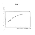
- FIG. 3 is a graph showing a reducing agent injection amount and a temperature difference between a front and a rear of a catalyst in an exemplary exhaust system according to the present invention.
- FIG. 4 is a graph showing a temperature difference between a front and a rear of a catalyst depending on the travel distance in an exemplary exhaust system according to the present invention.
- FIG. 5 is a graph showing characteristics of a trapping filter that is equipped in an exemplary exhaust system according to the present invention.
- FIG. 1 is a schematic diagram of an exhaust system according to an exemplary embodiment of the present invention.
- an exhaust system includes an engine 100, an exhaust line 110, a first oxygen sensor 140a, an injector 120, a third temperature sensor T4, a fuel cracking catalyst 140, a fourth temperature sensor T5, a trapping filter 150, a first temperature sensor T6, a nitrogen oxide purification catalyst 130, a second oxygen sensor 140b, and a second temperature sensor T7.
- a control portion 105 may be realized as at least one microprocessor programmed with a predetermined program, and the predetermined program may include a set of instructions for performing methods according to an exemplary embodiment of the present invention.
- the first oxygen sensor 140a On the exhaust line 110, the first oxygen sensor 140a, the injector 120, the third temperature sensor T4, the fuel cracking catalyst 140, the fourth temperature sensor T5, the trapping filter 150, the first temperature sensor T6, the nitrogen oxide purification catalyst 130, the second oxygen sensor 140b, and the second temperature sensor T7 are sequentially disposed.
- the first oxygen sensor 140a and the second oxygen sensor 140b detect an oxygen concentration difference passing through the exhaust line 110, and transfer the detected signals to control portion 105.
- the control portion 105 detects regeneration timing of the trapping filter 150 or the nitrogen oxide purification catalyst 130, and controls the injector to inject fuel depending on the regeneration timing.
- the fuel injected by the injector 120 passes the fuel cracking catalyst 140, and is activated to be transformed to a reducing agent such as a hydrocarbon, etc.
- the fuel cracking catalyst 140 performs DFC (diesel fuel cracking) that activates diesel fuel.
- the fuel cracking catalyst 140 can be a DOC (diesel oxidation catalyst) that oxidizes or reduces harmful materials of the exhaust gas, or can include a catalyst performing functions of the DOC.
- DOC diesel oxidation catalyst
- the trapping filter 150 filters particulate materials of the exhaust gas that is exhausted from the engine, and burns to eliminate the filtered particulate materials depending on the regeneration cycle.
- the particulate materials that are trapped in the trapping filter 150 can be eliminated in a condition of higher than a predetermined temperature.
- the trapped particulate materials in the trapping filter 150 are combusted by fuel injected from the engine 100.
- the control portion 105 compares the HC ratio to NOx in a real driving condition with a predetermined value of the map data, and if the HC ratio to NOx is lower than a predetermined value, the injector 120 is operated to inject fuel into the exhaust gas.
- the control portion 105 controls a fuel injection amount and injection timing based on signals detected from the sensors and the map data in such a manner that the nitrogen oxide trapped in the nitrogen oxide purification catalyst 130 is desorbed to be reduced by the reducing agent.
- FIG. 2A and FIG. 2B are control flowcharts of an exhaust system according to an exemplary embodiment of the present invention.
- the control method of the exhaust system includes a set of instructions for performing a zero step S200, a first step S201, a second step S202, a third step S203, a fourth step S204, a fifth step S205, a sixth step S206, an eighth step S208, a ninth step S209, a tenth step S210, an eleventh step S211, a twelfth step S212, a thirteenth step S213, a fourteenth step S214, a fifteenth step S215, a sixteenth step S216, a seventeenth step S217, and a eighteenth step S218.
- the engine 100 is started, and in the first step S201, it is determined whether the regeneration condition of the nitrogen oxide purification catalyst 130 or the regeneration(desulfurization) condition of the trapping filter is satisfied or not.
- the injector 120 injects fuel as a reducing agent in the second step S202.
- the temperature difference between the upstream side and the downstream side of the fuel cracking catalyst 140 is detected, and the temperature difference between the upstream side and the downstream side of the nitrogen oxide purification catalyst 130 is detected in the third step S203.
- an oxygen concentration difference between the first oxygen sensor 140a and the second oxygen sensor 140b is detected in the third step S203.
- the temperature difference between the front side and the rear side of the fuel cracking catalyst 140 is larger than a predetermined value in the fourth step S204, it is determined whether the temperature difference between the front side and the rear side of the nitrogen oxide purification catalyst 130 is larger than a predetermined value in the fifth step S205, and if the temperature difference is larger than that, it is determined whether the oxygen concentration difference between the first oxygen sensor 140a and the second oxygen sensor 140b is larger than a predetermined value in the sixth step S206.
- the temperature difference between the front side and the rear side of the fuel cracking catalyst 140, the temperature difference between the front side and the rear side of the nitrogen oxide purification catalyst 130, and the oxygen concentration difference between the first oxygen sensor 140a and the second oxygen sensor 140b are respectively larger than predetermined values in the fourth step S204, the fifth step S205, and the sixth step S206, it is determined as the normal driving state that the fuel cracking catalyst 140 and the nitrogen oxide purification catalyst 130 are not deteriorated.
- the engine 100 is normally operated in the eighth step S208.
- the fourteenth step S214, the fifteenth step S215, and the sixteenth step S216 are performed.
- the front/rear temperature difference of the nitrogen oxide purification catalyst 130 is larger than a predetermined value in the fourteenth step S214 and if the oxygen concentration difference between the first oxygen sensor and the second oxygen sensor 140b is larger than a predetermined value in the fifteenth step S215, it is determined whether the nitrogen oxide purification ratio of the nitrogen oxide purification catalyst 130 is smaller than a predetermined value in the sixteenth step S216.
- a method for calculating the purification ratio of the nitrogen oxide purification catalyst 130 is well known, so a detailed description is omitted in this description according to an exemplary embodiment of the present invention.
- step S216 it is determined whether the degraded fuel cracking catalyst 140 is being operated within a predetermined range of a maximum capacity.
- the purification ratio of the nitrogen oxide purification catalyst 130 is lower than a predetermined value in the sixteenth step S216, it is determined that the fuel cracking catalyst 140 does not operate in the seventeenth step S217, and then an emergency lamp is lit.
- the regeneration temperature of the trapping filter 150 is varied depending on the degradation rate of the fuel cracking catalyst 140 in the eighteenth step S218.
- the front/rear temperature difference of the nitrogen oxide purification catalyst 130 is smaller than a predetermined value in the fifth S205 and if the oxygen concentration difference between the first oxygen sensor 140a and the second oxygen sensor 140b is larger than a predetermined value in the ninth step S209, it is determined whether the nitrogen oxide purification ratio of the nitrogen oxide purification catalyst 130 is larger than or equal to a predetermined value in the tenth step S210.
- the injection amount of the injector is compensated in the thirteen step S213 to form a secondary injection of the injector 120.
- the degradation rate of the trapping filter 150 can be calculated based on the temperature difference between the temperature sensors T4 and T5 that are disposed at the front side and the rear side of the fuel cracking catalyst 140. That is, as the temperature difference becomes smaller, the degradation rate becomes larger.
- the relationship between the front/rear temperature difference and the degradation rate of the trapping filter 150 can be set by experimentation.
- the regeneration temperature of the trapping filter 150 can be varied to a relatively low value, and if the degradation rate of the trapping filter 150 is high, the regeneration temperature of the trapping filter 150 can be varied to a relatively high value.
- the regeneration temperature of the trapping filter 150 can be varied according to a predetermined map data. Further, the regeneration temperature, a regeneration cycle, and regeneration time of the trapping filter 150 can be varied depending on the degradation rate of the trapping filter 150.
- FIG. 3 is a graph showing a reducing agent injection amount and a temperature difference between a front and a rear of a catalyst in an exhaust system according to an exemplary embodiment of the present invention.
- the front/rear temperature difference of the nitrogen oxide purification catalyst 130 or the fuel cracking catalyst 140 becomes larger.
- the high temperature exhaust gas is supplied to the rear side thereof.
- FIG. 4 is a graph showing a temperature difference between a front and a rear of a catalyst depending on the travel distance in an exhaust system according to an exemplary embodiment of the present invention.
- the front/rear temperature difference of the nitrogen oxide purification catalyst 130 or the fuel cracking catalyst 140 becomes smaller, if predetermined conditions are identical.
- the oxidation rate thereof is decreased, such that the exhaust gas temperature, which is supplied to the rear side thereof, is relatively lowered.
- FIG. 5 is a graph showing characteristics of a trapping filter that is equipped in an exhaust system according to an exemplary embodiment of the present invention.
- the horizontal axis signifies trapping filters according to the deterioration rate thereof
- the vertical axis signifies the regeneration efficiency thereof.
- regeneration efficiency of a conventional trapping filter is about 85%, and regeneration efficiency of the trapping filter according to an exemplary embodiment of the present invention is about 98% as a low temperature regeneration type.
- a low temperature regeneration catalyst is coated in the trapping filter, differently from a general trapping filter.
- PM partate materials
- the horizontal axis shows two trapping filters of which degradation rate of one is low and degradation rate of the other is high, and the vertical axis shows regeneration efficiency depending on the degradation rate.
- regeneration efficiency of a trapping filter having a low degradation rate is about 88%
- regeneration efficiency of a trapping filter having a high degradation rate is about 92%.
- the fuel cracking catalyst can include an oxidation catalyst function or can be changed to an oxidation catalyst in FIG. 1 , FIG. 2A , and FIG. 2B according to an exemplary embodiment of the present invention.
- the oxidation catalyst has a function of purifying harmful material included in the exhaust gas through oxidation/reduction reactions, and the fuel cracking catalyst can have an oxidation catalyst function for purifying harmful material included in the exhaust gas in an exemplary embodiment of the present invention.
Landscapes
- Engineering & Computer Science (AREA)
- Chemical & Material Sciences (AREA)
- Combustion & Propulsion (AREA)
- Mechanical Engineering (AREA)
- General Engineering & Computer Science (AREA)
- Chemical Kinetics & Catalysis (AREA)
- Materials Engineering (AREA)
- Health & Medical Sciences (AREA)
- Toxicology (AREA)
- Exhaust Gas After Treatment (AREA)
- Processes For Solid Components From Exhaust (AREA)
Abstract
Description
- The present application claims priority to Korean Patent Application No.
10-2009-0105016, filed on November 2, 2009 - The present invention relates to an exhaust system. More particularly, the present invention relates to an exhaust system that traps particulate materials included in the exhaust gas, and eliminates the trapped particulate materials in a predetermined condition.
- Generally, exhaust gas that is exhausted through an exhaust manifold of an engine is induced to pass through a catalytic converter that is mounted in the middle of an exhaust pipe to be purified, and the noise thereof is reduced while passing through a muffler before the exhaust gas is discharged to the outside through a tail pipe.
- The catalytic converter processes the pollution materials that are included in the exhaust gas. Further, a particulate filter is mounted on the exhaust pipe to trap particulate material (PM) that is included in the exhaust gas.
- A selective catalytic reduction device is a type of catalytic converter. Reducing agents such as carbon monoxide, total hydrocarbon (THC), and so on react well with nitrogen oxide rather than oxygen in the selective catalyst reduction apparatus (SCR), which is why it is called a selective catalyst reduction apparatus (SCR).
- In an internal combustion engine to which the selective catalyst reduction apparatus is installed, the fuel is continuously and additionally injected according to the nitrogen oxide amount in the exhaust gas. Accordingly, the hydrocarbon can be slipped from the selective catalyst reduction apparatus, and the fuel consumption is increased.
- Also, when the reducing agent is continuously supplied, an oxidation/reduction reaction is also continuously performed in the exhaust pipe. Accordingly, the durability of the catalyst is deteriorated by reaction heat that is formed during the oxidation/reduction reaction.
- The information disclosed in this Background of the Invention section is only for enhancement of understanding of the general background of the invention and should not be taken as an acknowledgement or any form of suggestion that this information forms the prior art already known to a person skilled in the art.
- Various aspects of the present invention are directed to provide an exhaust system having advantages of varying a regeneration temperature depending on the degradation rate of a catalyst.
- In an aspect of the present invention, the exhaust system, may include a trapping filter that is disposed at an exhaust line to trap particulate material of exhaust gas, a nitrogen oxide purification catalyst that is disposed at a downstream side of the trapping filter to eliminate nitrogen oxide of the exhaust gas, an injector that selectively injects fuel in the exhaust line, a fuel cracking catalyst that is disposed between the injector and the trapping filter at the exhaust line, transforms the injected fuel to a reducing agent, and raises the temperature of the downstream side thereof, and a control portion that controls the injector to inject a predetermined amount of the fuel for a predetermined time period so as to raise the temperature of the trapping filter to a predetermined regeneration temperature and eliminate the particulate material trapped in the trapping filter, wherein the control portion detects a degradation rate of the fuel cracking catalyst, and varies the predetermined regeneration temperature of the trapping filter depending on the degradation rate.
- The fuel cracking catalyst may include a DOC (diesel oxidation catalyst)
- The nitrogen oxide purification catalyst may use the reducing agent that is formed by the fuel cracking catalyst to detach and reduce the nitrogen oxide in the nitrogen oxide purification catalyst,
- When the ratio of the nitrogen trapped in the nitrogen oxide purification catalyst to HC of the exhaust gas is lower than a predetermined value, the controller may control the injector to inject the predetermined amount of the fuel for the predetermined time period into the exhaust gas.
- The control portion may use a temperature difference between an upstream side and a downstream side of the fuel cracking catalyst to detect the degradation rate thereof, and varies the degeneration rate when it is determined that the temperature difference thereof is smaller than a predetermined value after the injector injects the fuel.
- The control portion may use a temperature difference between an upstream side and a downstream side of the nitrogen oxide purification catalyst to detect the degradation rate thereof, and varies the degeneration rate when it is determined that the temperature difference thereof is larger than or equal to a predetermined value after the injector injects fuel.
- The control portion may detect the degradation rate of the fuel cracking catalyst by using an oxygen concentration difference between an upstream side and the downstream side of the fuel cracking catalyst, and varies the degradation rate when it is determined that the oxygen concentration difference is larger than a predetermined value after the injector injects fuel.
- The control portion may detect the degradation rate of the fuel cracking catalyst by using a purification ratio of the nitrogen oxide purification catalyst, and varies the degradation rate when it is determined that the purification ratio of the nitrogen oxide purification catalyst is larger than or equal to a predetermined value.
- The control portion may compensate the predetermined injection amount and the predetermined time period of the injector when a temperature difference between an upstream side and a downstream side of the fuel cracking catalyst is smaller than a predetermined value, a temperature difference between an upstream side and a downstream side of the nitrogen oxide purification catalyst is smaller than a predetermined value, an oxygen concentration difference between an upstream side and the downstream side of the fuel cracking catalyst is larger than a predetermined value, and a purification ratio of the nitrogen oxide purification catalyst is larger than or equal to a predetermined value.
- The injector may include a first injector that is configured to inject fuel in intake air or into a cylinder of an engine, or a second injector that is disposed at the exhaust line.
- In another aspect of the present invention, a method of controlling an exhaust system, may include steps of determining whether a regeneration condition of a nitrogen oxide purification catalyst or a regeneration condition of a trapping filter is satisfied or not, injecting a predetermined amount of fuel for a predetermined time period as a reducing agent when either or both of the regeneration conditions are satisfied, determining whether a first temperature difference between a front side and a rear side of a fuel cracking catalyst is larger than or equal to a first predetermined value, determining whether a second temperature difference between a front side and a rear side of the nitrogen oxide purification catalyst is larger than or equal to a second predetermined value, determining whether an oxygen concentration difference between an upstream of the fuel cracking catalyst and a downstream of the nitrogen oxide purification catalyst is larger than a third predetermined value, and changing a regeneration target temperature of the trapping filter when the first temperature difference is smaller than the first predetermined value, the second temperature difference is larger than or equal to the second predetermined value, the oxygen concentration difference is larger than the third predetermined value, and a purification ratio of the nitrogen oxide purification catalyst is larger than or equal to a fourth predetermined value, wherein the trapping filter is disposed at an exhaust line, the nitrogen oxide purification catalyst is disposed at a downstream side of the trapping filter, and the fuel cracking catalyst is disposed between the injector and the trapping filter at the exhaust line.
- The method may further include compensating the predetermined injection amount and the predetermined time period of the injector when the first temperature difference is larger than or equal to the second predetermined value, the second temperature difference is smaller than the second predetermined value, the oxygen concentration difference is larger than the third predetermined value, and the purification ratio of the nitrogen oxide purification catalyst is larger than or equal to the fourth predetermined value.
- The method may further include determining as a normal driving state, when the first temperature difference is larger than or equal to the first predetermined value, the second temperature difference is larger than or equal to the second predetermined value, and the oxygen concentration difference is larger than the third predetermined value.
- As stated above, if the degradation rate of the fuel cracking catalyst is higher than a predetermined value, the regeneration temperature of the trapping filter is varied so as to raise the regeneration efficiency thereof.
- Further, CO/THC is hardly slipped through the trapping filter, such that the degradation of the nitrogen oxide purification catalyst is prevented.
- The methods and apparatuses of the present invention have other features and advantages which will be apparent from or are set forth in more detail in the accompanying drawings, which are incorporated herein, and the following Detailed Description of the Invention, which together serve to explain certain principles of the present invention.
-
FIG. 1 is a schematic diagram of an exemplary exhaust system according to the present invention. -
FIG. 2A andFIG. 2B are control flowcharts of an exemplary exhaust system according to the present invention. -
FIG. 3 is a graph showing a reducing agent injection amount and a temperature difference between a front and a rear of a catalyst in an exemplary exhaust system according to the present invention. -
FIG. 4 is a graph showing a temperature difference between a front and a rear of a catalyst depending on the travel distance in an exemplary exhaust system according to the present invention. -
FIG. 5 is a graph showing characteristics of a trapping filter that is equipped in an exemplary exhaust system according to the present invention. - It should be understood that the appended drawings are not necessarily to scale, presenting a somewhat simplified representation of various features illustrative of the basic principles of the invention. The specific design features of the present invention as disclosed herein, including, for example, specific dimensions, orientations, locations, and shapes will be determined in part by the particular intended application and use environment.
- In the figures, reference numbers refer to the same or equivalent parts of the present invention throughout the several figures of the drawing.
- Reference will now be made in detail to various embodiments of the present invention(s), examples of which are illustrated in the accompanying drawings and described below. While the invention(s) will be described in conjunction with exemplary embodiments, it will be understood that present description is not intended to limit the invention(s) to those exemplary embodiments. On the contrary, the invention(s) is/are intended to cover not only the exemplary embodiments, but also various alternatives, modifications, equivalents and other embodiments, which may be included within the spirit and scope of the invention as defined by the appended claims.
-
FIG. 1 is a schematic diagram of an exhaust system according to an exemplary embodiment of the present invention. - Referring to
FIG. 1 , an exhaust system includes anengine 100, anexhaust line 110, afirst oxygen sensor 140a, aninjector 120, a third temperature sensor T4, afuel cracking catalyst 140, a fourth temperature sensor T5, atrapping filter 150, a first temperature sensor T6, a nitrogenoxide purification catalyst 130, asecond oxygen sensor 140b, and a second temperature sensor T7. - A
control portion 105 may be realized as at least one microprocessor programmed with a predetermined program, and the predetermined program may include a set of instructions for performing methods according to an exemplary embodiment of the present invention. - On the
exhaust line 110, thefirst oxygen sensor 140a, theinjector 120, the third temperature sensor T4, thefuel cracking catalyst 140, the fourth temperature sensor T5, thetrapping filter 150, the first temperature sensor T6, the nitrogenoxide purification catalyst 130, thesecond oxygen sensor 140b, and the second temperature sensor T7 are sequentially disposed. - The
first oxygen sensor 140a and thesecond oxygen sensor 140b detect an oxygen concentration difference passing through theexhaust line 110, and transfer the detected signals tocontrol portion 105. - The
control portion 105 detects regeneration timing of thetrapping filter 150 or the nitrogenoxide purification catalyst 130, and controls the injector to inject fuel depending on the regeneration timing. - The fuel injected by the
injector 120 passes thefuel cracking catalyst 140, and is activated to be transformed to a reducing agent such as a hydrocarbon, etc. The fuel cracking catalyst 140 performs DFC (diesel fuel cracking) that activates diesel fuel. - Also, in an exemplary embodiment of the present invention, the
fuel cracking catalyst 140 can be a DOC (diesel oxidation catalyst) that oxidizes or reduces harmful materials of the exhaust gas, or can include a catalyst performing functions of the DOC. - The
trapping filter 150 filters particulate materials of the exhaust gas that is exhausted from the engine, and burns to eliminate the filtered particulate materials depending on the regeneration cycle. Here, the particulate materials that are trapped in thetrapping filter 150 can be eliminated in a condition of higher than a predetermined temperature. - In this case, the trapped particulate materials in the
trapping filter 150 are combusted by fuel injected from theengine 100. - Meanwhile, the ratio of the nitrogen trapped in the nitrogen
oxide purification catalyst 130 and the HC of the exhaust gas is set in map data beforehand, thecontrol portion 105 compares the HC ratio to NOx in a real driving condition with a predetermined value of the map data, and if the HC ratio to NOx is lower than a predetermined value, theinjector 120 is operated to inject fuel into the exhaust gas. - The
control portion 105 controls a fuel injection amount and injection timing based on signals detected from the sensors and the map data in such a manner that the nitrogen oxide trapped in the nitrogenoxide purification catalyst 130 is desorbed to be reduced by the reducing agent. -
FIG. 2A andFIG. 2B are control flowcharts of an exhaust system according to an exemplary embodiment of the present invention. - Referring to
FIG. 2A andFIG. 2B , the control method of the exhaust system includes a set of instructions for performing a zero step S200, a first step S201, a second step S202, a third step S203, a fourth step S204, a fifth step S205, a sixth step S206, an eighth step S208, a ninth step S209, a tenth step S210, an eleventh step S211, a twelfth step S212, a thirteenth step S213, a fourteenth step S214, a fifteenth step S215, a sixteenth step S216, a seventeenth step S217, and a eighteenth step S218. - In the zero step S200, the
engine 100 is started, and in the first step S201, it is determined whether the regeneration condition of the nitrogenoxide purification catalyst 130 or the regeneration(desulfurization) condition of the trapping filter is satisfied or not. - If the condition is satisfied, the
injector 120 injects fuel as a reducing agent in the second step S202. - If the fuel is injected by the
injector 120, the temperature difference between the upstream side and the downstream side of thefuel cracking catalyst 140 is detected, and the temperature difference between the upstream side and the downstream side of the nitrogenoxide purification catalyst 130 is detected in the third step S203. - Further, an oxygen concentration difference between the
first oxygen sensor 140a and thesecond oxygen sensor 140b is detected in the third step S203. - If it is determined that the temperature difference between the front side and the rear side of the
fuel cracking catalyst 140 is larger than a predetermined value in the fourth step S204, it is determined whether the temperature difference between the front side and the rear side of the nitrogenoxide purification catalyst 130 is larger than a predetermined value in the fifth step S205, and if the temperature difference is larger than that, it is determined whether the oxygen concentration difference between thefirst oxygen sensor 140a and thesecond oxygen sensor 140b is larger than a predetermined value in the sixth step S206. - If the temperature difference between the front side and the rear side of the
fuel cracking catalyst 140, the temperature difference between the front side and the rear side of the nitrogenoxide purification catalyst 130, and the oxygen concentration difference between thefirst oxygen sensor 140a and thesecond oxygen sensor 140b are respectively larger than predetermined values in the fourth step S204, the fifth step S205, and the sixth step S206, it is determined as the normal driving state that thefuel cracking catalyst 140 and the nitrogenoxide purification catalyst 130 are not deteriorated. - If it is determined that the
fuel cracking catalyst 140 and the nitrogenoxide purification catalyst 130 are not degraded, theengine 100 is normally operated in the eighth step S208. - If the temperature difference between the front side and the rear side of the
fuel cracking catalyst 140 is lower than a predetermined value in the fourth step S204, the fourteenth step S214, the fifteenth step S215, and the sixteenth step S216 are performed. - If the front/rear temperature difference of the nitrogen
oxide purification catalyst 130 is larger than a predetermined value in the fourteenth step S214 and if the oxygen concentration difference between the first oxygen sensor and thesecond oxygen sensor 140b is larger than a predetermined value in the fifteenth step S215, it is determined whether the nitrogen oxide purification ratio of the nitrogenoxide purification catalyst 130 is smaller than a predetermined value in the sixteenth step S216. - A method for calculating the purification ratio of the nitrogen
oxide purification catalyst 130 is well known, so a detailed description is omitted in this description according to an exemplary embodiment of the present invention. - In the sixteenth step S216, it is determined whether the degraded
fuel cracking catalyst 140 is being operated within a predetermined range of a maximum capacity. - If the purification ratio of the nitrogen
oxide purification catalyst 130 is lower than a predetermined value in the sixteenth step S216, it is determined that thefuel cracking catalyst 140 does not operate in the seventeenth step S217, and then an emergency lamp is lit. - Further, if it is determined that the nitrogen
oxide purification catalyst 130 has a predetermined purification ratio in the sixteenth step S216, the regeneration temperature of the trappingfilter 150 is varied depending on the degradation rate of thefuel cracking catalyst 140 in the eighteenth step S218. - If the front/rear temperature difference of the nitrogen
oxide purification catalyst 130 is smaller than a predetermined value in the fifth S205 and if the oxygen concentration difference between thefirst oxygen sensor 140a and thesecond oxygen sensor 140b is larger than a predetermined value in the ninth step S209, it is determined whether the nitrogen oxide purification ratio of the nitrogenoxide purification catalyst 130 is larger than or equal to a predetermined value in the tenth step S210. - If it is determined that the nitrogen oxide purification ratio of the nitrogen
oxide purification catalyst 130 is larger than or equal to a predetermined value in the tenth step S210, the injection amount of the injector is compensated in the thirteen step S213 to form a secondary injection of theinjector 120. - However, if it is determined that the nitrogen oxide purification ratio of the nitrogen
oxide purification catalyst 130 is smaller than a predetermined value in the tenth step S210, an emergency lamp is lit and the secondary injection of theinjector 120 is cut off in the eleventh step S211. - As described above, the degradation rate of the trapping
filter 150 can be calculated based on the temperature difference between the temperature sensors T4 and T5 that are disposed at the front side and the rear side of thefuel cracking catalyst 140. That is, as the temperature difference becomes smaller, the degradation rate becomes larger. - The relationship between the front/rear temperature difference and the degradation rate of the trapping
filter 150 can be set by experimentation. - For example, if the degradation rate of the trapping
filter 150 is low, the regeneration temperature of the trappingfilter 150 can be varied to a relatively low value, and if the degradation rate of the trappingfilter 150 is high, the regeneration temperature of the trappingfilter 150 can be varied to a relatively high value. - In an exemplary embodiment of the present invention, the regeneration temperature of the trapping
filter 150 can be varied according to a predetermined map data. Further, the regeneration temperature, a regeneration cycle, and regeneration time of the trappingfilter 150 can be varied depending on the degradation rate of the trappingfilter 150. -
FIG. 3 is a graph showing a reducing agent injection amount and a temperature difference between a front and a rear of a catalyst in an exhaust system according to an exemplary embodiment of the present invention. - Referring to
FIG. 3 , as the fuel injection amount that is injected through theinjector 120 as a reducing agent becomes larger, the front/rear temperature difference of the nitrogenoxide purification catalyst 130 or thefuel cracking catalyst 140 becomes larger. - Since the injected fuel passes the nitrogen
oxide purification catalyst 130 or thefuel cracking catalyst 140 to be oxidized, the high temperature exhaust gas is supplied to the rear side thereof. -
FIG. 4 is a graph showing a temperature difference between a front and a rear of a catalyst depending on the travel distance in an exhaust system according to an exemplary embodiment of the present invention. - Referring to
FIG. 4 , as the engine operating time or the travel distance of a vehicle becomes longer, the front/rear temperature difference of the nitrogenoxide purification catalyst 130 or thefuel cracking catalyst 140 becomes smaller, if predetermined conditions are identical. - That is, as the travel distance becomes longer, catalyst elements included in the nitrogen
oxide purification catalyst 130 or thefuel cracking catalyst 140 are degraded and the performance thereof is deteriorated. - Accordingly, after the fuel is injected through the
injector 120, when the injected fuel passes the catalysts, the oxidation rate thereof is decreased, such that the exhaust gas temperature, which is supplied to the rear side thereof, is relatively lowered. -
FIG. 5 is a graph showing characteristics of a trapping filter that is equipped in an exhaust system according to an exemplary embodiment of the present invention. - Referring to (a) of
FIG. 5 , the horizontal axis signifies trapping filters according to the deterioration rate thereof, and the vertical axis signifies the regeneration efficiency thereof. - In the same condition in which the trapping amount is 8g/L and the regeneration temperature is 580 °C, regeneration efficiency of a conventional trapping filter is about 85%, and regeneration efficiency of the trapping filter according to an exemplary embodiment of the present invention is about 98% as a low temperature regeneration type.
- A low temperature regeneration catalyst is coated in the trapping filter, differently from a general trapping filter. Thus, in a case that the same amount of PM (particulate materials) is trapped, high regeneration efficiency is achieved at a relatively low temperature.
- If a low temperature regeneration catalyst is applied, an injected amount is decreased. Thus, fuel is saved, and degradation speed of the catalyst becomes slow.
- Referring to (b) of
FIG. 5 , the horizontal axis shows two trapping filters of which degradation rate of one is low and degradation rate of the other is high, and the vertical axis shows regeneration efficiency depending on the degradation rate. - In a case that a trapping filter is regenerated at 620°C , regeneration efficiency of a trapping filter having a low degradation rate is about 88%, and regeneration efficiency of a trapping filter having a high degradation rate is about 92%.
- That is, as the degradation rate is increased, it has to be regenerated at a higher temperature so as to raise regeneration efficiency.
- Further, the fuel cracking catalyst can include an oxidation catalyst function or can be changed to an oxidation catalyst in
FIG. 1 ,FIG. 2A , andFIG. 2B according to an exemplary embodiment of the present invention. - The oxidation catalyst has a function of purifying harmful material included in the exhaust gas through oxidation/reduction reactions, and the fuel cracking catalyst can have an oxidation catalyst function for purifying harmful material included in the exhaust gas in an exemplary embodiment of the present invention.
- For convenience in explanation and accurate definition in the appended claims, the terms "upstream", "downstream", "front" or "rear" are used to describe features of the exemplary embodiments with reference to the positions of such features as displayed in the figures.
- The foregoing descriptions of specific exemplary embodiments of the present invention have been presented for purposes of illustration and description. They are not intended to be exhaustive or to limit the invention to the precise forms disclosed, and obviously many modifications and variations are possible in light of the above teachings. The exemplary embodiments were chosen and described in order to explain certain principles of the invention and their practical application, to thereby enable others skilled in the art to make and utilize various exemplary embodiments of the present invention, as well as various alternatives and modifications thereof. It is intended that the scope of the invention be defined by the Claims appended hereto and their equivalents.
Claims (13)
- An exhaust system, comprising:a trapping filter that is disposed at an exhaust line to trap particulate material of exhaust gas;a nitrogen oxide purification catalyst that is disposed at a downstream side of the trapping filter to eliminate nitrogen oxide of the exhaust gas;an injector that selectively injects fuel in the exhaust line;a fuel cracking catalyst that is disposed between the injector and the trapping filter at the exhaust line, transforms the injected fuel to a reducing agent, and raises the temperature of the downstream side thereof; anda control portion that controls the injector to inject a predetermined amount of the fuel for a predetermined time period so as to raise the temperature of the trapping filter to a predetermined regeneration temperature and eliminate the particulate material trapped in the trapping filter,wherein the control portion detects a degradation rate of the fuel cracking catalyst, and varies the predetermined regeneration temperature of the trapping filter depending on the degradation rate.
- The exhaust system of claim 1, wherein the fuel cracking catalyst includes a DOC (diesel oxidation catalyst)
- The exhaust system of claim 1, wherein the nitrogen oxide purification catalyst uses the reducing agent that is formed by the fuel cracking catalyst to detach and reduce the nitrogen oxide in the nitrogen oxide purification catalyst.
- The exhaust system of claim 3, wherein, when the ratio of the nitrogen trapped in the nitrogen oxide purification catalyst to HC of the exhaust gas is lower than a predetermined value, the controller controls the injector to inject the predetermined amount of the fuel for the predetermined time period into the exhaust gas.
- The exhaust system of claim 3, wherein the control portion uses a temperature difference between an upstream side and a downstream side of the fuel cracking catalyst to detect the degradation rate thereof, and varies the degeneration rate when it is determined that the temperature difference thereof is smaller than a predetermined value after the injector injects the fuel.
- The exhaust system of claim 5, wherein the control portion uses a temperature difference between an upstream side and a downstream side of the nitrogen oxide purification catalyst to detect the degradation rate thereof, and varies the degeneration rate when it is determined that the temperature difference thereof is larger than or equal to a predetermined value after the injector injects fuel.
- The exhaust system of claim 6, wherein the control portion detects the degradation rate of the fuel cracking catalyst by using an oxygen concentration difference between an upstream side and the downstream side of the fuel cracking catalyst, and varies the degradation rate when it is determined that the oxygen concentration difference is larger than a predetermined value after the injector injects fuel.
- The exhaust system of claim 7, wherein the control portion detects the degradation rate of the fuel cracking catalyst by using a purification ratio of the nitrogen oxide purification catalyst, and varies the degradation rate when it is determined that the purification ratio of the nitrogen oxide purification catalyst is larger than or equal to a predetermined value.
- The exhaust system of claim 3, wherein the control portion compensates the predetermined injection amount and the predetermined time period of the injector when a temperature difference between an upstream side and a downstream side of the fuel cracking catalyst is smaller than a predetermined value, a temperature difference between an upstream side and a downstream side of the nitrogen oxide purification catalyst is smaller than a predetermined value, an oxygen concentration difference between an upstream side and the downstream side of the fuel cracking catalyst is larger than a predetermined value, and a purification ratio of the nitrogen oxide purification catalyst is larger than or equal to a predetermined value.
- The exhaust system of claim 1, wherein the injector includes a first injector that is configured to inject fuel in intake air or into a cylinder of an engine, or a second injector that is disposed at the exhaust line.
- A method of controlling an exhaust system, comprising steps of:determining whether a regeneration condition of a nitrogen oxide purification catalyst or a regeneration condition of a trapping filter is satisfied or not;injecting a predetermined amount of fuel for a predetermined time period as a reducing agent when either or both of the regeneration conditions are satisfied;determining whether a first temperature difference between a front side and a rear side of a fuel cracking catalyst is larger than or equal to a first predetermined value;determining whether a second temperature difference between a front side and a rear side of the nitrogen oxide purification catalyst is larger than or equal to a second predetermined value;determining whether an oxygen concentration difference between an upstream of the fuel cracking catalyst and a downstream of the nitrogen oxide purification catalyst is larger than a third predetermined value; andchanging a regeneration target temperature of the trapping filter when the first temperature difference is smaller than the first predetermined value, the second temperature difference is larger than or equal to the second predetermined value, the oxygen concentration difference is larger than the third predetermined value, and a purification ratio of the nitrogen oxide purification catalyst is larger than or equal to a fourth predetermined value,wherein the trapping filter is disposed at an exhaust line;the nitrogen oxide purification catalyst is disposed at a downstream side of the trapping filter; andthe fuel cracking catalyst is disposed between the injector and the trapping filter at the exhaust line.
- The method of claim 11, further comprising:compensating the predetermined injection amount and the predetermined time period of the injector when the first temperature difference is larger than or equal to the second predetermined value, the second temperature difference is smaller than the second predetermined value, the oxygen concentration difference is larger than the third predetermined value, and the purification ratio of the nitrogen oxide purification catalyst is larger than or equal to the fourth predetermined value.
- The method of claim 11, further comprising:determining as a normal driving state, when the first temperature difference is larger than or equal to the first predetermined value, the second temperature difference is larger than or equal to the second predetermined value, and the oxygen concentration difference is larger than the third predetermined value.
Applications Claiming Priority (1)
| Application Number | Priority Date | Filing Date | Title |
|---|---|---|---|
| KR1020090105016A KR101048144B1 (en) | 2009-11-02 | 2009-11-02 | Exhaust system |
Publications (3)
| Publication Number | Publication Date |
|---|---|
| EP2317089A2 true EP2317089A2 (en) | 2011-05-04 |
| EP2317089A3 EP2317089A3 (en) | 2011-12-07 |
| EP2317089B1 EP2317089B1 (en) | 2015-03-25 |
Family
ID=43513680
Family Applications (1)
| Application Number | Title | Priority Date | Filing Date |
|---|---|---|---|
| EP10168510.5A Not-in-force EP2317089B1 (en) | 2009-11-02 | 2010-07-06 | Exhaust system |
Country Status (4)
| Country | Link |
|---|---|
| US (1) | US8555619B2 (en) |
| EP (1) | EP2317089B1 (en) |
| KR (1) | KR101048144B1 (en) |
| CN (1) | CN102052125B (en) |
Families Citing this family (12)
| Publication number | Priority date | Publication date | Assignee | Title |
|---|---|---|---|---|
| KR101189241B1 (en) | 2010-12-02 | 2012-10-09 | 현대자동차주식회사 | METHOD FOR PREDICTING REGENERATION OF DeNOx CATALYST AND EXHAUST SYSTEM USING THE SAME |
| KR101251519B1 (en) | 2010-12-02 | 2013-04-05 | 현대자동차주식회사 | METHOD FOR PREDICTING SOx STORED AT DeNOx CATALYST AND EXHAUST SYSTEM USING THE SAME |
| KR101251505B1 (en) * | 2010-12-02 | 2013-04-05 | 현대자동차주식회사 | METHOD FOR PREDICTING NOx LOADING AT DeNOx CATALYST AND EXHAUST SYSTEM USING THE SAME |
| US20120222399A1 (en) * | 2011-03-03 | 2012-09-06 | GM Global Technology Operations LLC | Oxidation catalyst burn threshold adjustment to avoid quenching |
| US9371763B2 (en) * | 2011-03-21 | 2016-06-21 | GM Global Technology Operations LLC | Method of operating an exhaust gas treatment system to prevent quenching during regeneration |
| KR101316843B1 (en) * | 2011-06-29 | 2013-10-10 | 기아자동차주식회사 | Improving method fuel efficiecnt based on mileage |
| US8505284B2 (en) * | 2011-07-26 | 2013-08-13 | GM Global Technology Operations LLC | Stratified particulate filter regeneration system |
| JP5790545B2 (en) * | 2012-03-05 | 2015-10-07 | 三菱自動車工業株式会社 | Catalyst diagnostic apparatus and catalyst diagnostic method |
| KR101628098B1 (en) * | 2014-11-03 | 2016-06-08 | 현대자동차 주식회사 | Exhaust gas purification system for vehicle |
| JP6711214B2 (en) * | 2016-08-31 | 2020-06-17 | いすゞ自動車株式会社 | Vehicle aftertreatment system and vehicle aftertreatment method |
| CN112664298A (en) * | 2020-06-16 | 2021-04-16 | 长城汽车股份有限公司 | Exhaust gas purification system for vehicle and exhaust gas purification method for vehicle |
| KR102745483B1 (en) * | 2023-09-08 | 2024-12-19 | 주식회사 현대케피코 | Lambda Prediction Method and Lambda Prediction System for Exhaust Gas Post-Treatment System |
Family Cites Families (19)
| Publication number | Priority date | Publication date | Assignee | Title |
|---|---|---|---|---|
| US5630315A (en) * | 1995-10-06 | 1997-05-20 | General Motors Corporation | Catalyst diagnostic system and method |
| JP4253986B2 (en) * | 2000-03-03 | 2009-04-15 | マツダ株式会社 | In-cylinder injection engine control device |
| US6983589B2 (en) * | 2003-05-07 | 2006-01-10 | Ford Global Technologies, Llc | Diesel aftertreatment systems |
| US7168237B2 (en) * | 2004-02-27 | 2007-01-30 | Nissan Motor Co., Ltd. | Deterioration diagnosing device and diagnosing method for exhaust gas purification catalyst |
| US8056325B2 (en) * | 2005-01-14 | 2011-11-15 | Toyota Jidosha Kabushiki Kaisha | Exhaust gas purification apparatus regeneration system of internal combustion engine |
| EP1857647A4 (en) * | 2005-01-31 | 2015-03-25 | Isuzu Motors Ltd | Method of raising temperature of exhaust-gas purifier and exhaust-gas purification system |
| KR20060102003A (en) * | 2005-03-22 | 2006-09-27 | 한국델파이주식회사 | Soot purification device for diesel vehicles |
| JP4434061B2 (en) * | 2005-04-08 | 2010-03-17 | トヨタ自動車株式会社 | Exhaust gas purification device for internal combustion engine |
| US20090044517A1 (en) * | 2005-07-06 | 2009-02-19 | Takahiro Oba | Exhaust gas purification system for an internal combustion engine |
| JP2007064167A (en) * | 2005-09-02 | 2007-03-15 | Toyota Motor Corp | Exhaust gas purification device and exhaust gas purification method for internal combustion engine |
| JP4710564B2 (en) * | 2005-11-22 | 2011-06-29 | いすゞ自動車株式会社 | Exhaust gas purification system control method and exhaust gas purification system |
| US8148290B2 (en) * | 2006-06-27 | 2012-04-03 | Basf Corporation | Diesel exhaust treatment system catalyst monitoring |
| KR100836367B1 (en) * | 2006-11-21 | 2008-06-09 | 현대자동차주식회사 | Purifier for Reducing Particulate Matter and Nitrogen Oxide in Diesel Engine |
| US8171721B2 (en) * | 2007-01-22 | 2012-05-08 | International Engine Intellectual Property Company, Llc | Closed loop control of exhaust system fluid dosing |
| DE102008049098A1 (en) * | 2008-09-26 | 2009-06-25 | Daimler Ag | Exhaust-gas cleaning system operating method for e.g. diesel engine of motor vehicle, involves determining aging condition of exhaust gas cleaning component by correlation of hydrocarbon existed in exhaust gas upstream of component |
| DE102008049099A1 (en) * | 2008-09-26 | 2009-06-10 | Daimler Ag | Emission control equipment operating method for diesel engine of motor vehicle, involves decreasing nitrogen-dioxide content during exceeding of preset nitrogen-dioxide threshold value in exhaust gas |
| US7942043B2 (en) * | 2009-02-19 | 2011-05-17 | Detroit Diesel Corporation | On-board aftertreatment device tail pipe hydrocarbon slip calculation |
| KR20110012498A (en) * | 2009-07-30 | 2011-02-09 | 현대자동차주식회사 | Exhaust system |
| KR20110023158A (en) * | 2009-08-28 | 2011-03-08 | 현대자동차주식회사 | Exhaust system |
-
2009
- 2009-11-02 KR KR1020090105016A patent/KR101048144B1/en not_active Expired - Fee Related
-
2010
- 2010-07-06 EP EP10168510.5A patent/EP2317089B1/en not_active Not-in-force
- 2010-07-13 US US12/835,274 patent/US8555619B2/en not_active Expired - Fee Related
- 2010-07-23 CN CN201010236699.3A patent/CN102052125B/en not_active Expired - Fee Related
Non-Patent Citations (1)
| Title |
|---|
| None |
Also Published As
| Publication number | Publication date |
|---|---|
| KR20110048278A (en) | 2011-05-11 |
| US20110099976A1 (en) | 2011-05-05 |
| US8555619B2 (en) | 2013-10-15 |
| CN102052125B (en) | 2015-06-17 |
| KR101048144B1 (en) | 2011-07-08 |
| EP2317089B1 (en) | 2015-03-25 |
| EP2317089A3 (en) | 2011-12-07 |
| CN102052125A (en) | 2011-05-11 |
Similar Documents
| Publication | Publication Date | Title |
|---|---|---|
| EP2317089B1 (en) | Exhaust system | |
| EP2295751B1 (en) | Exhaust system | |
| US8776505B2 (en) | Method for predicting NOx amount and exhaust system using the same | |
| US9133746B2 (en) | Method for predicting NOx loading at DeNOx catalyst and exhaust system using the same | |
| US8720190B2 (en) | Method for predicting SOx stored at DeNOx catalyst and exhaust system using the same | |
| US8528321B2 (en) | Exhaust purification system for internal combustion engine and desulfurization method for the same | |
| EP2455599B1 (en) | Method for predicting NOx amount and exhaust system using the same | |
| EP2719872A1 (en) | Exhaust gas purification system for vehicle and regeneration control method thereof | |
| US10287944B2 (en) | Exhaust purification system and method of desulfurizing lean NOx trap of exhaust purification system provided with lean NOx trap and selective catalytic reduction catalyst | |
| US8327624B2 (en) | System for purifying exhaust gas | |
| US20130091828A1 (en) | System and Method for Regenerating Gasoline Particulate Filter | |
| US8601797B2 (en) | Exhaust device for diesel vehicle | |
| EP3546713A2 (en) | Exhaust purification device and exhaust purification method for internal combustion engine | |
| US8763373B2 (en) | System for purifying exhaust gas and method for controlling the same | |
| EP3546714A2 (en) | Exhaust purification device and exhaust purification method for internal combustion engine | |
| Sharma et al. | DPF Passive Regeneration Approach for CEV/TREM-V Off-Highway Applications |
Legal Events
| Date | Code | Title | Description |
|---|---|---|---|
| PUAI | Public reference made under article 153(3) epc to a published international application that has entered the european phase |
Free format text: ORIGINAL CODE: 0009012 |
|
| AK | Designated contracting states |
Kind code of ref document: A2 Designated state(s): AL AT BE BG CH CY CZ DE DK EE ES FI FR GB GR HR HU IE IS IT LI LT LU LV MC MK MT NL NO PL PT RO SE SI SK SM TR |
|
| AX | Request for extension of the european patent |
Extension state: BA ME RS |
|
| PUAL | Search report despatched |
Free format text: ORIGINAL CODE: 0009013 |
|
| AK | Designated contracting states |
Kind code of ref document: A3 Designated state(s): AL AT BE BG CH CY CZ DE DK EE ES FI FR GB GR HR HU IE IS IT LI LT LU LV MC MK MT NL NO PL PT RO SE SI SK SM TR |
|
| AX | Request for extension of the european patent |
Extension state: BA ME RS |
|
| RIC1 | Information provided on ipc code assigned before grant |
Ipc: F01N 9/00 20060101ALI20111101BHEP Ipc: F02D 41/02 20060101ALN20111101BHEP Ipc: F02D 41/00 20060101ALI20111101BHEP Ipc: F02D 41/14 20060101ALN20111101BHEP Ipc: F01N 13/02 20100101ALN20111101BHEP Ipc: F01N 3/023 20060101AFI20111101BHEP Ipc: F01N 11/00 20060101ALI20111101BHEP |
|
| 17P | Request for examination filed |
Effective date: 20120223 |
|
| RIC1 | Information provided on ipc code assigned before grant |
Ipc: F02D 41/02 20060101ALN20130218BHEP Ipc: F01N 9/00 20060101ALI20130218BHEP Ipc: F01N 3/023 20060101AFI20130218BHEP Ipc: F01N 11/00 20060101ALI20130218BHEP Ipc: F02D 41/14 20060101ALN20130218BHEP Ipc: F01N 13/02 20100101ALN20130218BHEP Ipc: F02D 41/00 20060101ALI20130218BHEP |
|
| 17Q | First examination report despatched |
Effective date: 20130321 |
|
| RIC1 | Information provided on ipc code assigned before grant |
Ipc: F02D 41/14 20060101ALN20131007BHEP Ipc: F01N 11/00 20060101ALI20131007BHEP Ipc: F01N 13/02 20100101ALN20131007BHEP Ipc: F02D 41/00 20060101ALI20131007BHEP Ipc: F01N 3/023 20060101AFI20131007BHEP Ipc: F02D 41/02 20060101ALN20131007BHEP Ipc: F01N 9/00 20060101ALI20131007BHEP |
|
| GRAP | Despatch of communication of intention to grant a patent |
Free format text: ORIGINAL CODE: EPIDOSNIGR1 |
|
| INTG | Intention to grant announced |
Effective date: 20131206 |
|
| RIC1 | Information provided on ipc code assigned before grant |
Ipc: F01N 3/023 20060101AFI20131127BHEP Ipc: F01N 13/02 20100101ALN20131127BHEP Ipc: F02D 41/00 20060101ALI20131127BHEP Ipc: F02D 41/02 20060101ALN20131127BHEP Ipc: F02D 41/14 20060101ALN20131127BHEP Ipc: F01N 9/00 20060101ALI20131127BHEP Ipc: F01N 11/00 20060101ALI20131127BHEP |
|
| GRAP | Despatch of communication of intention to grant a patent |
Free format text: ORIGINAL CODE: EPIDOSNIGR1 |
|
| RIC1 | Information provided on ipc code assigned before grant |
Ipc: F02D 41/00 20060101ALI20140317BHEP Ipc: F02D 41/14 20060101ALN20140317BHEP Ipc: F01N 9/00 20060101ALI20140317BHEP Ipc: F02D 41/02 20060101ALN20140317BHEP Ipc: F01N 3/023 20060101AFI20140317BHEP Ipc: F01N 13/02 20100101ALN20140317BHEP Ipc: F01N 11/00 20060101ALI20140317BHEP |
|
| INTG | Intention to grant announced |
Effective date: 20140416 |
|
| RAP1 | Party data changed (applicant data changed or rights of an application transferred) |
Owner name: HYUNDAI MOTOR COMPANY Owner name: KIA MOTORS CORPORATION |
|
| GRAP | Despatch of communication of intention to grant a patent |
Free format text: ORIGINAL CODE: EPIDOSNIGR1 |
|
| RIC1 | Information provided on ipc code assigned before grant |
Ipc: F02D 41/02 20060101ALN20141007BHEP Ipc: F02D 41/00 20060101ALI20141007BHEP Ipc: F01N 13/02 20100101ALN20141007BHEP Ipc: F01N 11/00 20060101ALI20141007BHEP Ipc: F01N 9/00 20060101ALI20141007BHEP Ipc: F01N 3/023 20060101AFI20141007BHEP Ipc: F02D 41/14 20060101ALN20141007BHEP |
|
| INTG | Intention to grant announced |
Effective date: 20141023 |
|
| GRAS | Grant fee paid |
Free format text: ORIGINAL CODE: EPIDOSNIGR3 |
|
| GRAA | (expected) grant |
Free format text: ORIGINAL CODE: 0009210 |
|
| AK | Designated contracting states |
Kind code of ref document: B1 Designated state(s): AL AT BE BG CH CY CZ DE DK EE ES FI FR GB GR HR HU IE IS IT LI LT LU LV MC MK MT NL NO PL PT RO SE SI SK SM TR |
|
| REG | Reference to a national code |
Ref country code: GB Ref legal event code: FG4D |
|
| REG | Reference to a national code |
Ref country code: CH Ref legal event code: EP |
|
| REG | Reference to a national code |
Ref country code: IE Ref legal event code: FG4D |
|
| REG | Reference to a national code |
Ref country code: DE Ref legal event code: R096 Ref document number: 602010023333 Country of ref document: DE Effective date: 20150507 |
|
| REG | Reference to a national code |
Ref country code: AT Ref legal event code: REF Ref document number: 718019 Country of ref document: AT Kind code of ref document: T Effective date: 20150515 |
|
| PG25 | Lapsed in a contracting state [announced via postgrant information from national office to epo] |
Ref country code: NO Free format text: LAPSE BECAUSE OF FAILURE TO SUBMIT A TRANSLATION OF THE DESCRIPTION OR TO PAY THE FEE WITHIN THE PRESCRIBED TIME-LIMIT Effective date: 20150625 Ref country code: HR Free format text: LAPSE BECAUSE OF FAILURE TO SUBMIT A TRANSLATION OF THE DESCRIPTION OR TO PAY THE FEE WITHIN THE PRESCRIBED TIME-LIMIT Effective date: 20150325 Ref country code: FI Free format text: LAPSE BECAUSE OF FAILURE TO SUBMIT A TRANSLATION OF THE DESCRIPTION OR TO PAY THE FEE WITHIN THE PRESCRIBED TIME-LIMIT Effective date: 20150325 Ref country code: SE Free format text: LAPSE BECAUSE OF FAILURE TO SUBMIT A TRANSLATION OF THE DESCRIPTION OR TO PAY THE FEE WITHIN THE PRESCRIBED TIME-LIMIT Effective date: 20150325 Ref country code: LT Free format text: LAPSE BECAUSE OF FAILURE TO SUBMIT A TRANSLATION OF THE DESCRIPTION OR TO PAY THE FEE WITHIN THE PRESCRIBED TIME-LIMIT Effective date: 20150325 |
|
| REG | Reference to a national code |
Ref country code: AT Ref legal event code: MK05 Ref document number: 718019 Country of ref document: AT Kind code of ref document: T Effective date: 20150325 |
|
| REG | Reference to a national code |
Ref country code: LT Ref legal event code: MG4D |
|
| PG25 | Lapsed in a contracting state [announced via postgrant information from national office to epo] |
Ref country code: GR Free format text: LAPSE BECAUSE OF FAILURE TO SUBMIT A TRANSLATION OF THE DESCRIPTION OR TO PAY THE FEE WITHIN THE PRESCRIBED TIME-LIMIT Effective date: 20150626 Ref country code: LV Free format text: LAPSE BECAUSE OF FAILURE TO SUBMIT A TRANSLATION OF THE DESCRIPTION OR TO PAY THE FEE WITHIN THE PRESCRIBED TIME-LIMIT Effective date: 20150325 |
|
| PG25 | Lapsed in a contracting state [announced via postgrant information from national office to epo] |
Ref country code: NL Free format text: LAPSE BECAUSE OF FAILURE TO SUBMIT A TRANSLATION OF THE DESCRIPTION OR TO PAY THE FEE WITHIN THE PRESCRIBED TIME-LIMIT Effective date: 20150325 |
|
| PG25 | Lapsed in a contracting state [announced via postgrant information from national office to epo] |
Ref country code: CZ Free format text: LAPSE BECAUSE OF FAILURE TO SUBMIT A TRANSLATION OF THE DESCRIPTION OR TO PAY THE FEE WITHIN THE PRESCRIBED TIME-LIMIT Effective date: 20150325 Ref country code: EE Free format text: LAPSE BECAUSE OF FAILURE TO SUBMIT A TRANSLATION OF THE DESCRIPTION OR TO PAY THE FEE WITHIN THE PRESCRIBED TIME-LIMIT Effective date: 20150325 Ref country code: PT Free format text: LAPSE BECAUSE OF FAILURE TO SUBMIT A TRANSLATION OF THE DESCRIPTION OR TO PAY THE FEE WITHIN THE PRESCRIBED TIME-LIMIT Effective date: 20150727 Ref country code: SK Free format text: LAPSE BECAUSE OF FAILURE TO SUBMIT A TRANSLATION OF THE DESCRIPTION OR TO PAY THE FEE WITHIN THE PRESCRIBED TIME-LIMIT Effective date: 20150325 Ref country code: RO Free format text: LAPSE BECAUSE OF FAILURE TO SUBMIT A TRANSLATION OF THE DESCRIPTION OR TO PAY THE FEE WITHIN THE PRESCRIBED TIME-LIMIT Effective date: 20150325 Ref country code: ES Free format text: LAPSE BECAUSE OF FAILURE TO SUBMIT A TRANSLATION OF THE DESCRIPTION OR TO PAY THE FEE WITHIN THE PRESCRIBED TIME-LIMIT Effective date: 20150325 |
|
| PG25 | Lapsed in a contracting state [announced via postgrant information from national office to epo] |
Ref country code: AT Free format text: LAPSE BECAUSE OF FAILURE TO SUBMIT A TRANSLATION OF THE DESCRIPTION OR TO PAY THE FEE WITHIN THE PRESCRIBED TIME-LIMIT Effective date: 20150325 Ref country code: PL Free format text: LAPSE BECAUSE OF FAILURE TO SUBMIT A TRANSLATION OF THE DESCRIPTION OR TO PAY THE FEE WITHIN THE PRESCRIBED TIME-LIMIT Effective date: 20150325 Ref country code: IS Free format text: LAPSE BECAUSE OF FAILURE TO SUBMIT A TRANSLATION OF THE DESCRIPTION OR TO PAY THE FEE WITHIN THE PRESCRIBED TIME-LIMIT Effective date: 20150725 |
|
| REG | Reference to a national code |
Ref country code: DE Ref legal event code: R097 Ref document number: 602010023333 Country of ref document: DE |
|
| PG25 | Lapsed in a contracting state [announced via postgrant information from national office to epo] |
Ref country code: DK Free format text: LAPSE BECAUSE OF FAILURE TO SUBMIT A TRANSLATION OF THE DESCRIPTION OR TO PAY THE FEE WITHIN THE PRESCRIBED TIME-LIMIT Effective date: 20150325 |
|
| PLBE | No opposition filed within time limit |
Free format text: ORIGINAL CODE: 0009261 |
|
| STAA | Information on the status of an ep patent application or granted ep patent |
Free format text: STATUS: NO OPPOSITION FILED WITHIN TIME LIMIT |
|
| PG25 | Lapsed in a contracting state [announced via postgrant information from national office to epo] |
Ref country code: MC Free format text: LAPSE BECAUSE OF FAILURE TO SUBMIT A TRANSLATION OF THE DESCRIPTION OR TO PAY THE FEE WITHIN THE PRESCRIBED TIME-LIMIT Effective date: 20150325 |
|
| REG | Reference to a national code |
Ref country code: CH Ref legal event code: PL |
|
| 26N | No opposition filed |
Effective date: 20160105 |
|
| PG25 | Lapsed in a contracting state [announced via postgrant information from national office to epo] |
Ref country code: LU Free format text: LAPSE BECAUSE OF FAILURE TO SUBMIT A TRANSLATION OF THE DESCRIPTION OR TO PAY THE FEE WITHIN THE PRESCRIBED TIME-LIMIT Effective date: 20150706 |
|
| REG | Reference to a national code |
Ref country code: IE Ref legal event code: MM4A |
|
| PG25 | Lapsed in a contracting state [announced via postgrant information from national office to epo] |
Ref country code: IT Free format text: LAPSE BECAUSE OF FAILURE TO SUBMIT A TRANSLATION OF THE DESCRIPTION OR TO PAY THE FEE WITHIN THE PRESCRIBED TIME-LIMIT Effective date: 20150325 Ref country code: CH Free format text: LAPSE BECAUSE OF NON-PAYMENT OF DUE FEES Effective date: 20150731 Ref country code: LI Free format text: LAPSE BECAUSE OF NON-PAYMENT OF DUE FEES Effective date: 20150731 |
|
| PG25 | Lapsed in a contracting state [announced via postgrant information from national office to epo] |
Ref country code: SI Free format text: LAPSE BECAUSE OF FAILURE TO SUBMIT A TRANSLATION OF THE DESCRIPTION OR TO PAY THE FEE WITHIN THE PRESCRIBED TIME-LIMIT Effective date: 20150325 |
|
| REG | Reference to a national code |
Ref country code: FR Ref legal event code: PLFP Year of fee payment: 7 |
|
| PG25 | Lapsed in a contracting state [announced via postgrant information from national office to epo] |
Ref country code: IE Free format text: LAPSE BECAUSE OF NON-PAYMENT OF DUE FEES Effective date: 20150706 |
|
| PG25 | Lapsed in a contracting state [announced via postgrant information from national office to epo] |
Ref country code: BE Free format text: LAPSE BECAUSE OF FAILURE TO SUBMIT A TRANSLATION OF THE DESCRIPTION OR TO PAY THE FEE WITHIN THE PRESCRIBED TIME-LIMIT Effective date: 20150325 |
|
| PG25 | Lapsed in a contracting state [announced via postgrant information from national office to epo] |
Ref country code: MT Free format text: LAPSE BECAUSE OF FAILURE TO SUBMIT A TRANSLATION OF THE DESCRIPTION OR TO PAY THE FEE WITHIN THE PRESCRIBED TIME-LIMIT Effective date: 20150325 |
|
| PG25 | Lapsed in a contracting state [announced via postgrant information from national office to epo] |
Ref country code: HU Free format text: LAPSE BECAUSE OF FAILURE TO SUBMIT A TRANSLATION OF THE DESCRIPTION OR TO PAY THE FEE WITHIN THE PRESCRIBED TIME-LIMIT; INVALID AB INITIO Effective date: 20100706 Ref country code: SM Free format text: LAPSE BECAUSE OF FAILURE TO SUBMIT A TRANSLATION OF THE DESCRIPTION OR TO PAY THE FEE WITHIN THE PRESCRIBED TIME-LIMIT Effective date: 20150325 Ref country code: BG Free format text: LAPSE BECAUSE OF FAILURE TO SUBMIT A TRANSLATION OF THE DESCRIPTION OR TO PAY THE FEE WITHIN THE PRESCRIBED TIME-LIMIT Effective date: 20150325 |
|
| PG25 | Lapsed in a contracting state [announced via postgrant information from national office to epo] |
Ref country code: CY Free format text: LAPSE BECAUSE OF FAILURE TO SUBMIT A TRANSLATION OF THE DESCRIPTION OR TO PAY THE FEE WITHIN THE PRESCRIBED TIME-LIMIT Effective date: 20150325 |
|
| REG | Reference to a national code |
Ref country code: FR Ref legal event code: PLFP Year of fee payment: 8 |
|
| PG25 | Lapsed in a contracting state [announced via postgrant information from national office to epo] |
Ref country code: TR Free format text: LAPSE BECAUSE OF FAILURE TO SUBMIT A TRANSLATION OF THE DESCRIPTION OR TO PAY THE FEE WITHIN THE PRESCRIBED TIME-LIMIT Effective date: 20150325 |
|
| REG | Reference to a national code |
Ref country code: FR Ref legal event code: PLFP Year of fee payment: 9 |
|
| PG25 | Lapsed in a contracting state [announced via postgrant information from national office to epo] |
Ref country code: MK Free format text: LAPSE BECAUSE OF FAILURE TO SUBMIT A TRANSLATION OF THE DESCRIPTION OR TO PAY THE FEE WITHIN THE PRESCRIBED TIME-LIMIT Effective date: 20150325 |
|
| PG25 | Lapsed in a contracting state [announced via postgrant information from national office to epo] |
Ref country code: AL Free format text: LAPSE BECAUSE OF FAILURE TO SUBMIT A TRANSLATION OF THE DESCRIPTION OR TO PAY THE FEE WITHIN THE PRESCRIBED TIME-LIMIT Effective date: 20150325 |
|
| P01 | Opt-out of the competence of the unified patent court (upc) registered |
Effective date: 20230527 |
|
| PGFP | Annual fee paid to national office [announced via postgrant information from national office to epo] |
Ref country code: FR Payment date: 20230621 Year of fee payment: 14 |
|
| PGFP | Annual fee paid to national office [announced via postgrant information from national office to epo] |
Ref country code: GB Payment date: 20230620 Year of fee payment: 14 |
|
| PGFP | Annual fee paid to national office [announced via postgrant information from national office to epo] |
Ref country code: DE Payment date: 20230620 Year of fee payment: 14 |
|
| REG | Reference to a national code |
Ref country code: DE Ref legal event code: R119 Ref document number: 602010023333 Country of ref document: DE |
|
| GBPC | Gb: european patent ceased through non-payment of renewal fee |
Effective date: 20240706 |
|
| PG25 | Lapsed in a contracting state [announced via postgrant information from national office to epo] |
Ref country code: DE Free format text: LAPSE BECAUSE OF NON-PAYMENT OF DUE FEES Effective date: 20250201 |
|
| PG25 | Lapsed in a contracting state [announced via postgrant information from national office to epo] |
Ref country code: FR Free format text: LAPSE BECAUSE OF NON-PAYMENT OF DUE FEES Effective date: 20240731 |
|
| PG25 | Lapsed in a contracting state [announced via postgrant information from national office to epo] |
Ref country code: GB Free format text: LAPSE BECAUSE OF NON-PAYMENT OF DUE FEES Effective date: 20240706 |