EP2316984A1 - Hard film, plastic working die, plastic working method, and target for hard film - Google Patents
Hard film, plastic working die, plastic working method, and target for hard film Download PDFInfo
- Publication number
- EP2316984A1 EP2316984A1 EP10009513A EP10009513A EP2316984A1 EP 2316984 A1 EP2316984 A1 EP 2316984A1 EP 10009513 A EP10009513 A EP 10009513A EP 10009513 A EP10009513 A EP 10009513A EP 2316984 A1 EP2316984 A1 EP 2316984A1
- Authority
- EP
- European Patent Office
- Prior art keywords
- hard film
- plastic working
- atomic ratio
- film
- die
- Prior art date
- Legal status (The legal status is an assumption and is not a legal conclusion. Google has not performed a legal analysis and makes no representation as to the accuracy of the status listed.)
- Granted
Links
- 238000000034 method Methods 0.000 title claims description 24
- 239000000203 mixture Substances 0.000 claims abstract description 41
- 229910052727 yttrium Inorganic materials 0.000 claims abstract description 20
- XEEYBQQBJWHFJM-UHFFFAOYSA-N Iron Chemical compound [Fe] XEEYBQQBJWHFJM-UHFFFAOYSA-N 0.000 claims description 30
- 239000000463 material Substances 0.000 claims description 16
- 229910052742 iron Inorganic materials 0.000 claims description 15
- 229910052761 rare earth metal Inorganic materials 0.000 claims description 11
- 229910021480 group 4 element Inorganic materials 0.000 claims description 9
- 229910021478 group 5 element Inorganic materials 0.000 claims description 9
- 229910021476 group 6 element Inorganic materials 0.000 claims description 9
- 238000004080 punching Methods 0.000 claims description 6
- 238000012360 testing method Methods 0.000 description 21
- 238000000151 deposition Methods 0.000 description 11
- 230000008021 deposition Effects 0.000 description 8
- 239000000758 substrate Substances 0.000 description 8
- 229910052804 chromium Inorganic materials 0.000 description 6
- 229910052751 metal Inorganic materials 0.000 description 6
- 239000002245 particle Substances 0.000 description 6
- 230000015572 biosynthetic process Effects 0.000 description 5
- 239000002131 composite material Substances 0.000 description 5
- 150000004767 nitrides Chemical class 0.000 description 5
- 229910000831 Steel Inorganic materials 0.000 description 4
- 238000005520 cutting process Methods 0.000 description 4
- 230000003647 oxidation Effects 0.000 description 4
- 238000007254 oxidation reaction Methods 0.000 description 4
- 239000010959 steel Substances 0.000 description 4
- 230000000694 effects Effects 0.000 description 3
- 230000002708 enhancing effect Effects 0.000 description 3
- 230000002349 favourable effect Effects 0.000 description 3
- 238000012423 maintenance Methods 0.000 description 3
- 238000004519 manufacturing process Methods 0.000 description 3
- 229910052755 nonmetal Inorganic materials 0.000 description 3
- 229910045601 alloy Inorganic materials 0.000 description 2
- 239000000956 alloy Substances 0.000 description 2
- 238000004140 cleaning Methods 0.000 description 2
- 239000013078 crystal Substances 0.000 description 2
- 238000005516 engineering process Methods 0.000 description 2
- 230000008020 evaporation Effects 0.000 description 2
- 238000001704 evaporation Methods 0.000 description 2
- 238000005242 forging Methods 0.000 description 2
- 230000001965 increasing effect Effects 0.000 description 2
- 150000002500 ions Chemical class 0.000 description 2
- 238000005259 measurement Methods 0.000 description 2
- 239000000523 sample Substances 0.000 description 2
- 229910052684 Cerium Inorganic materials 0.000 description 1
- 229910052692 Dysprosium Inorganic materials 0.000 description 1
- 229910052691 Erbium Inorganic materials 0.000 description 1
- 229910052693 Europium Inorganic materials 0.000 description 1
- 229910052688 Gadolinium Inorganic materials 0.000 description 1
- 229910052689 Holmium Inorganic materials 0.000 description 1
- 229910052765 Lutetium Inorganic materials 0.000 description 1
- 229910001122 Mischmetal Inorganic materials 0.000 description 1
- 229910052779 Neodymium Inorganic materials 0.000 description 1
- 229910052777 Praseodymium Inorganic materials 0.000 description 1
- 229910052772 Samarium Inorganic materials 0.000 description 1
- 229910052771 Terbium Inorganic materials 0.000 description 1
- 229910052775 Thulium Inorganic materials 0.000 description 1
- ATJFFYVFTNAWJD-UHFFFAOYSA-N Tin Chemical compound [Sn] ATJFFYVFTNAWJD-UHFFFAOYSA-N 0.000 description 1
- 229910001315 Tool steel Inorganic materials 0.000 description 1
- 229910052769 Ytterbium Inorganic materials 0.000 description 1
- 239000011195 cermet Substances 0.000 description 1
- 230000000052 comparative effect Effects 0.000 description 1
- 150000001875 compounds Chemical class 0.000 description 1
- 238000004453 electron probe microanalysis Methods 0.000 description 1
- 238000011156 evaluation Methods 0.000 description 1
- 238000010438 heat treatment Methods 0.000 description 1
- 238000007733 ion plating Methods 0.000 description 1
- 229910052746 lanthanum Inorganic materials 0.000 description 1
- 238000001755 magnetron sputter deposition Methods 0.000 description 1
- 239000002184 metal Substances 0.000 description 1
- 150000001247 metal acetylides Chemical class 0.000 description 1
- 238000003825 pressing Methods 0.000 description 1
- 230000001681 protective effect Effects 0.000 description 1
- 230000009257 reactivity Effects 0.000 description 1
- 229910052706 scandium Inorganic materials 0.000 description 1
- 239000006104 solid solution Substances 0.000 description 1
- 229910052720 vanadium Inorganic materials 0.000 description 1
- LEONUFNNVUYDNQ-UHFFFAOYSA-N vanadium atom Chemical compound [V] LEONUFNNVUYDNQ-UHFFFAOYSA-N 0.000 description 1
Images
Classifications
-
- C—CHEMISTRY; METALLURGY
- C23—COATING METALLIC MATERIAL; COATING MATERIAL WITH METALLIC MATERIAL; CHEMICAL SURFACE TREATMENT; DIFFUSION TREATMENT OF METALLIC MATERIAL; COATING BY VACUUM EVAPORATION, BY SPUTTERING, BY ION IMPLANTATION OR BY CHEMICAL VAPOUR DEPOSITION, IN GENERAL; INHIBITING CORROSION OF METALLIC MATERIAL OR INCRUSTATION IN GENERAL
- C23C—COATING METALLIC MATERIAL; COATING MATERIAL WITH METALLIC MATERIAL; SURFACE TREATMENT OF METALLIC MATERIAL BY DIFFUSION INTO THE SURFACE, BY CHEMICAL CONVERSION OR SUBSTITUTION; COATING BY VACUUM EVAPORATION, BY SPUTTERING, BY ION IMPLANTATION OR BY CHEMICAL VAPOUR DEPOSITION, IN GENERAL
- C23C14/00—Coating by vacuum evaporation, by sputtering or by ion implantation of the coating forming material
- C23C14/22—Coating by vacuum evaporation, by sputtering or by ion implantation of the coating forming material characterised by the process of coating
- C23C14/34—Sputtering
- C23C14/3407—Cathode assembly for sputtering apparatus, e.g. Target
-
- C—CHEMISTRY; METALLURGY
- C23—COATING METALLIC MATERIAL; COATING MATERIAL WITH METALLIC MATERIAL; CHEMICAL SURFACE TREATMENT; DIFFUSION TREATMENT OF METALLIC MATERIAL; COATING BY VACUUM EVAPORATION, BY SPUTTERING, BY ION IMPLANTATION OR BY CHEMICAL VAPOUR DEPOSITION, IN GENERAL; INHIBITING CORROSION OF METALLIC MATERIAL OR INCRUSTATION IN GENERAL
- C23C—COATING METALLIC MATERIAL; COATING MATERIAL WITH METALLIC MATERIAL; SURFACE TREATMENT OF METALLIC MATERIAL BY DIFFUSION INTO THE SURFACE, BY CHEMICAL CONVERSION OR SUBSTITUTION; COATING BY VACUUM EVAPORATION, BY SPUTTERING, BY ION IMPLANTATION OR BY CHEMICAL VAPOUR DEPOSITION, IN GENERAL
- C23C14/00—Coating by vacuum evaporation, by sputtering or by ion implantation of the coating forming material
- C23C14/06—Coating by vacuum evaporation, by sputtering or by ion implantation of the coating forming material characterised by the coating material
-
- C—CHEMISTRY; METALLURGY
- C04—CEMENTS; CONCRETE; ARTIFICIAL STONE; CERAMICS; REFRACTORIES
- C04B—LIME, MAGNESIA; SLAG; CEMENTS; COMPOSITIONS THEREOF, e.g. MORTARS, CONCRETE OR LIKE BUILDING MATERIALS; ARTIFICIAL STONE; CERAMICS; REFRACTORIES; TREATMENT OF NATURAL STONE
- C04B35/00—Shaped ceramic products characterised by their composition; Ceramics compositions; Processing powders of inorganic compounds preparatory to the manufacturing of ceramic products
- C04B35/515—Shaped ceramic products characterised by their composition; Ceramics compositions; Processing powders of inorganic compounds preparatory to the manufacturing of ceramic products based on non-oxide ceramics
- C04B35/58—Shaped ceramic products characterised by their composition; Ceramics compositions; Processing powders of inorganic compounds preparatory to the manufacturing of ceramic products based on non-oxide ceramics based on borides, nitrides, i.e. nitrides, oxynitrides, carbonitrides or oxycarbonitrides or silicides
- C04B35/58007—Shaped ceramic products characterised by their composition; Ceramics compositions; Processing powders of inorganic compounds preparatory to the manufacturing of ceramic products based on non-oxide ceramics based on borides, nitrides, i.e. nitrides, oxynitrides, carbonitrides or oxycarbonitrides or silicides based on refractory metal nitrides
-
- C—CHEMISTRY; METALLURGY
- C04—CEMENTS; CONCRETE; ARTIFICIAL STONE; CERAMICS; REFRACTORIES
- C04B—LIME, MAGNESIA; SLAG; CEMENTS; COMPOSITIONS THEREOF, e.g. MORTARS, CONCRETE OR LIKE BUILDING MATERIALS; ARTIFICIAL STONE; CERAMICS; REFRACTORIES; TREATMENT OF NATURAL STONE
- C04B35/00—Shaped ceramic products characterised by their composition; Ceramics compositions; Processing powders of inorganic compounds preparatory to the manufacturing of ceramic products
- C04B35/515—Shaped ceramic products characterised by their composition; Ceramics compositions; Processing powders of inorganic compounds preparatory to the manufacturing of ceramic products based on non-oxide ceramics
- C04B35/58—Shaped ceramic products characterised by their composition; Ceramics compositions; Processing powders of inorganic compounds preparatory to the manufacturing of ceramic products based on non-oxide ceramics based on borides, nitrides, i.e. nitrides, oxynitrides, carbonitrides or oxycarbonitrides or silicides
- C04B35/58007—Shaped ceramic products characterised by their composition; Ceramics compositions; Processing powders of inorganic compounds preparatory to the manufacturing of ceramic products based on non-oxide ceramics based on borides, nitrides, i.e. nitrides, oxynitrides, carbonitrides or oxycarbonitrides or silicides based on refractory metal nitrides
- C04B35/58014—Shaped ceramic products characterised by their composition; Ceramics compositions; Processing powders of inorganic compounds preparatory to the manufacturing of ceramic products based on non-oxide ceramics based on borides, nitrides, i.e. nitrides, oxynitrides, carbonitrides or oxycarbonitrides or silicides based on refractory metal nitrides based on titanium nitrides, e.g. TiAlON
-
- C—CHEMISTRY; METALLURGY
- C04—CEMENTS; CONCRETE; ARTIFICIAL STONE; CERAMICS; REFRACTORIES
- C04B—LIME, MAGNESIA; SLAG; CEMENTS; COMPOSITIONS THEREOF, e.g. MORTARS, CONCRETE OR LIKE BUILDING MATERIALS; ARTIFICIAL STONE; CERAMICS; REFRACTORIES; TREATMENT OF NATURAL STONE
- C04B35/00—Shaped ceramic products characterised by their composition; Ceramics compositions; Processing powders of inorganic compounds preparatory to the manufacturing of ceramic products
- C04B35/515—Shaped ceramic products characterised by their composition; Ceramics compositions; Processing powders of inorganic compounds preparatory to the manufacturing of ceramic products based on non-oxide ceramics
- C04B35/58—Shaped ceramic products characterised by their composition; Ceramics compositions; Processing powders of inorganic compounds preparatory to the manufacturing of ceramic products based on non-oxide ceramics based on borides, nitrides, i.e. nitrides, oxynitrides, carbonitrides or oxycarbonitrides or silicides
- C04B35/581—Shaped ceramic products characterised by their composition; Ceramics compositions; Processing powders of inorganic compounds preparatory to the manufacturing of ceramic products based on non-oxide ceramics based on borides, nitrides, i.e. nitrides, oxynitrides, carbonitrides or oxycarbonitrides or silicides based on aluminium nitride
-
- C—CHEMISTRY; METALLURGY
- C23—COATING METALLIC MATERIAL; COATING MATERIAL WITH METALLIC MATERIAL; CHEMICAL SURFACE TREATMENT; DIFFUSION TREATMENT OF METALLIC MATERIAL; COATING BY VACUUM EVAPORATION, BY SPUTTERING, BY ION IMPLANTATION OR BY CHEMICAL VAPOUR DEPOSITION, IN GENERAL; INHIBITING CORROSION OF METALLIC MATERIAL OR INCRUSTATION IN GENERAL
- C23C—COATING METALLIC MATERIAL; COATING MATERIAL WITH METALLIC MATERIAL; SURFACE TREATMENT OF METALLIC MATERIAL BY DIFFUSION INTO THE SURFACE, BY CHEMICAL CONVERSION OR SUBSTITUTION; COATING BY VACUUM EVAPORATION, BY SPUTTERING, BY ION IMPLANTATION OR BY CHEMICAL VAPOUR DEPOSITION, IN GENERAL
- C23C14/00—Coating by vacuum evaporation, by sputtering or by ion implantation of the coating forming material
- C23C14/06—Coating by vacuum evaporation, by sputtering or by ion implantation of the coating forming material characterised by the coating material
- C23C14/0641—Nitrides
-
- C—CHEMISTRY; METALLURGY
- C23—COATING METALLIC MATERIAL; COATING MATERIAL WITH METALLIC MATERIAL; CHEMICAL SURFACE TREATMENT; DIFFUSION TREATMENT OF METALLIC MATERIAL; COATING BY VACUUM EVAPORATION, BY SPUTTERING, BY ION IMPLANTATION OR BY CHEMICAL VAPOUR DEPOSITION, IN GENERAL; INHIBITING CORROSION OF METALLIC MATERIAL OR INCRUSTATION IN GENERAL
- C23C—COATING METALLIC MATERIAL; COATING MATERIAL WITH METALLIC MATERIAL; SURFACE TREATMENT OF METALLIC MATERIAL BY DIFFUSION INTO THE SURFACE, BY CHEMICAL CONVERSION OR SUBSTITUTION; COATING BY VACUUM EVAPORATION, BY SPUTTERING, BY ION IMPLANTATION OR BY CHEMICAL VAPOUR DEPOSITION, IN GENERAL
- C23C14/00—Coating by vacuum evaporation, by sputtering or by ion implantation of the coating forming material
- C23C14/06—Coating by vacuum evaporation, by sputtering or by ion implantation of the coating forming material characterised by the coating material
- C23C14/0664—Carbonitrides
-
- C—CHEMISTRY; METALLURGY
- C23—COATING METALLIC MATERIAL; COATING MATERIAL WITH METALLIC MATERIAL; CHEMICAL SURFACE TREATMENT; DIFFUSION TREATMENT OF METALLIC MATERIAL; COATING BY VACUUM EVAPORATION, BY SPUTTERING, BY ION IMPLANTATION OR BY CHEMICAL VAPOUR DEPOSITION, IN GENERAL; INHIBITING CORROSION OF METALLIC MATERIAL OR INCRUSTATION IN GENERAL
- C23C—COATING METALLIC MATERIAL; COATING MATERIAL WITH METALLIC MATERIAL; SURFACE TREATMENT OF METALLIC MATERIAL BY DIFFUSION INTO THE SURFACE, BY CHEMICAL CONVERSION OR SUBSTITUTION; COATING BY VACUUM EVAPORATION, BY SPUTTERING, BY ION IMPLANTATION OR BY CHEMICAL VAPOUR DEPOSITION, IN GENERAL
- C23C14/00—Coating by vacuum evaporation, by sputtering or by ion implantation of the coating forming material
- C23C14/22—Coating by vacuum evaporation, by sputtering or by ion implantation of the coating forming material characterised by the process of coating
- C23C14/34—Sputtering
- C23C14/3407—Cathode assembly for sputtering apparatus, e.g. Target
- C23C14/3414—Metallurgical or chemical aspects of target preparation, e.g. casting, powder metallurgy
-
- C—CHEMISTRY; METALLURGY
- C23—COATING METALLIC MATERIAL; COATING MATERIAL WITH METALLIC MATERIAL; CHEMICAL SURFACE TREATMENT; DIFFUSION TREATMENT OF METALLIC MATERIAL; COATING BY VACUUM EVAPORATION, BY SPUTTERING, BY ION IMPLANTATION OR BY CHEMICAL VAPOUR DEPOSITION, IN GENERAL; INHIBITING CORROSION OF METALLIC MATERIAL OR INCRUSTATION IN GENERAL
- C23C—COATING METALLIC MATERIAL; COATING MATERIAL WITH METALLIC MATERIAL; SURFACE TREATMENT OF METALLIC MATERIAL BY DIFFUSION INTO THE SURFACE, BY CHEMICAL CONVERSION OR SUBSTITUTION; COATING BY VACUUM EVAPORATION, BY SPUTTERING, BY ION IMPLANTATION OR BY CHEMICAL VAPOUR DEPOSITION, IN GENERAL
- C23C28/00—Coating for obtaining at least two superposed coatings either by methods not provided for in a single one of groups C23C2/00 - C23C26/00 or by combinations of methods provided for in subclasses C23C and C25C or C25D
- C23C28/04—Coating for obtaining at least two superposed coatings either by methods not provided for in a single one of groups C23C2/00 - C23C26/00 or by combinations of methods provided for in subclasses C23C and C25C or C25D only coatings of inorganic non-metallic material
-
- C—CHEMISTRY; METALLURGY
- C23—COATING METALLIC MATERIAL; COATING MATERIAL WITH METALLIC MATERIAL; CHEMICAL SURFACE TREATMENT; DIFFUSION TREATMENT OF METALLIC MATERIAL; COATING BY VACUUM EVAPORATION, BY SPUTTERING, BY ION IMPLANTATION OR BY CHEMICAL VAPOUR DEPOSITION, IN GENERAL; INHIBITING CORROSION OF METALLIC MATERIAL OR INCRUSTATION IN GENERAL
- C23C—COATING METALLIC MATERIAL; COATING MATERIAL WITH METALLIC MATERIAL; SURFACE TREATMENT OF METALLIC MATERIAL BY DIFFUSION INTO THE SURFACE, BY CHEMICAL CONVERSION OR SUBSTITUTION; COATING BY VACUUM EVAPORATION, BY SPUTTERING, BY ION IMPLANTATION OR BY CHEMICAL VAPOUR DEPOSITION, IN GENERAL
- C23C30/00—Coating with metallic material characterised only by the composition of the metallic material, i.e. not characterised by the coating process
- C23C30/005—Coating with metallic material characterised only by the composition of the metallic material, i.e. not characterised by the coating process on hard metal substrates
-
- C—CHEMISTRY; METALLURGY
- C04—CEMENTS; CONCRETE; ARTIFICIAL STONE; CERAMICS; REFRACTORIES
- C04B—LIME, MAGNESIA; SLAG; CEMENTS; COMPOSITIONS THEREOF, e.g. MORTARS, CONCRETE OR LIKE BUILDING MATERIALS; ARTIFICIAL STONE; CERAMICS; REFRACTORIES; TREATMENT OF NATURAL STONE
- C04B2235/00—Aspects relating to ceramic starting mixtures or sintered ceramic products
- C04B2235/02—Composition of constituents of the starting material or of secondary phases of the final product
- C04B2235/30—Constituents and secondary phases not being of a fibrous nature
- C04B2235/38—Non-oxide ceramic constituents or additives
- C04B2235/3852—Nitrides, e.g. oxynitrides, carbonitrides, oxycarbonitrides, lithium nitride, magnesium nitride
-
- C—CHEMISTRY; METALLURGY
- C04—CEMENTS; CONCRETE; ARTIFICIAL STONE; CERAMICS; REFRACTORIES
- C04B—LIME, MAGNESIA; SLAG; CEMENTS; COMPOSITIONS THEREOF, e.g. MORTARS, CONCRETE OR LIKE BUILDING MATERIALS; ARTIFICIAL STONE; CERAMICS; REFRACTORIES; TREATMENT OF NATURAL STONE
- C04B2235/00—Aspects relating to ceramic starting mixtures or sintered ceramic products
- C04B2235/02—Composition of constituents of the starting material or of secondary phases of the final product
- C04B2235/30—Constituents and secondary phases not being of a fibrous nature
- C04B2235/38—Non-oxide ceramic constituents or additives
- C04B2235/3852—Nitrides, e.g. oxynitrides, carbonitrides, oxycarbonitrides, lithium nitride, magnesium nitride
- C04B2235/3856—Carbonitrides, e.g. titanium carbonitride, zirconium carbonitride
-
- C—CHEMISTRY; METALLURGY
- C04—CEMENTS; CONCRETE; ARTIFICIAL STONE; CERAMICS; REFRACTORIES
- C04B—LIME, MAGNESIA; SLAG; CEMENTS; COMPOSITIONS THEREOF, e.g. MORTARS, CONCRETE OR LIKE BUILDING MATERIALS; ARTIFICIAL STONE; CERAMICS; REFRACTORIES; TREATMENT OF NATURAL STONE
- C04B2235/00—Aspects relating to ceramic starting mixtures or sintered ceramic products
- C04B2235/02—Composition of constituents of the starting material or of secondary phases of the final product
- C04B2235/30—Constituents and secondary phases not being of a fibrous nature
- C04B2235/38—Non-oxide ceramic constituents or additives
- C04B2235/3852—Nitrides, e.g. oxynitrides, carbonitrides, oxycarbonitrides, lithium nitride, magnesium nitride
- C04B2235/386—Boron nitrides
-
- C—CHEMISTRY; METALLURGY
- C04—CEMENTS; CONCRETE; ARTIFICIAL STONE; CERAMICS; REFRACTORIES
- C04B—LIME, MAGNESIA; SLAG; CEMENTS; COMPOSITIONS THEREOF, e.g. MORTARS, CONCRETE OR LIKE BUILDING MATERIALS; ARTIFICIAL STONE; CERAMICS; REFRACTORIES; TREATMENT OF NATURAL STONE
- C04B2235/00—Aspects relating to ceramic starting mixtures or sintered ceramic products
- C04B2235/02—Composition of constituents of the starting material or of secondary phases of the final product
- C04B2235/30—Constituents and secondary phases not being of a fibrous nature
- C04B2235/38—Non-oxide ceramic constituents or additives
- C04B2235/3852—Nitrides, e.g. oxynitrides, carbonitrides, oxycarbonitrides, lithium nitride, magnesium nitride
- C04B2235/3865—Aluminium nitrides
-
- C—CHEMISTRY; METALLURGY
- C04—CEMENTS; CONCRETE; ARTIFICIAL STONE; CERAMICS; REFRACTORIES
- C04B—LIME, MAGNESIA; SLAG; CEMENTS; COMPOSITIONS THEREOF, e.g. MORTARS, CONCRETE OR LIKE BUILDING MATERIALS; ARTIFICIAL STONE; CERAMICS; REFRACTORIES; TREATMENT OF NATURAL STONE
- C04B2235/00—Aspects relating to ceramic starting mixtures or sintered ceramic products
- C04B2235/02—Composition of constituents of the starting material or of secondary phases of the final product
- C04B2235/30—Constituents and secondary phases not being of a fibrous nature
- C04B2235/38—Non-oxide ceramic constituents or additives
- C04B2235/3852—Nitrides, e.g. oxynitrides, carbonitrides, oxycarbonitrides, lithium nitride, magnesium nitride
- C04B2235/3873—Silicon nitrides, e.g. silicon carbonitride, silicon oxynitride
-
- C—CHEMISTRY; METALLURGY
- C04—CEMENTS; CONCRETE; ARTIFICIAL STONE; CERAMICS; REFRACTORIES
- C04B—LIME, MAGNESIA; SLAG; CEMENTS; COMPOSITIONS THEREOF, e.g. MORTARS, CONCRETE OR LIKE BUILDING MATERIALS; ARTIFICIAL STONE; CERAMICS; REFRACTORIES; TREATMENT OF NATURAL STONE
- C04B2235/00—Aspects relating to ceramic starting mixtures or sintered ceramic products
- C04B2235/02—Composition of constituents of the starting material or of secondary phases of the final product
- C04B2235/30—Constituents and secondary phases not being of a fibrous nature
- C04B2235/38—Non-oxide ceramic constituents or additives
- C04B2235/3852—Nitrides, e.g. oxynitrides, carbonitrides, oxycarbonitrides, lithium nitride, magnesium nitride
- C04B2235/3886—Refractory metal nitrides, e.g. vanadium nitride, tungsten nitride
Definitions
- the present invention relates to a hard film to be formed on the surface of a film-formed product such as a jig or a cutting tool, a plastic working die including the hard film formed therein, a plastic working method using a plastic working die including the hard film formed therein, and a target for a hard film which is for forming the hard film,
- plastic working dies using a cemented carbide, a cermet, a high-speed tool steel, or the like as the base material specifically, jigs such as dies for cold stamping, dies for punching, and forging dies, and cutting tools such as tips, drills, and end mills are each required to have excellent wear resistance and sliding characteristics. For this reason, a hard film is formed on each surface thereof.
- JP-A-2002-371352 there is a description to the effect that a vanadium-based film including one layer or two or more layers of any of VN film, VCN film, and VC film is formed.
- a film of TiN-TiCN-TiC applicable to use for pressing is formed.
- the carbide films which are the technologies described in JP-A-2002-371352 and JP-A-2008-207219 are each high in reactivity with an iron-based material, and is unfavorably insufficient in wear resistance particularly for forming of a high-strength steel sheet.
- the present invention was completed in view of the foregoing problem. It is therefore an object of the present invention to provide a hard film excellent in wear resistance, a plastic working die including the hard film formed therein, a plastic working method using a plastic working die including the hard film formed therein, and a target for a hard film which is for forming the hard film.
- the hard film in accordance with the present invention includes a nitride of metal elements of Ti, Cr, Al, and L (at least one of Si and Y) in the specific composition ratio.
- a nitride of metal elements of Ti, Cr, Al, and L at least one of Si and Y
- the hard film can acquire an excellent wear resistance.
- inclusion of at least one of B and C as a non-metal element in the specific composition ratio results in a lower coefficient of friction. Accordingly, the hard film is improved in sliding property, and hence, can acquire a more excellent wear resistance.
- the hard film in accordance with the present invention includes a nitride of Ti, Cr, Al, and L (at least one of Si and Y), and M (at least one of the group 4 elements (except for Ti), the group 5 elements, and the group 6 elements (except for Cr), and rare earth elements) in the specific composition ratio.
- the hard film can be more enhanced in hardness than the hard film of the item [1]. Accordingly, the hard film can acquire a still more excellent wear resistance.
- inclusion of at least one of B and C as a non-metal element in the specific composition ratio results in a lower coefficient of friction. Accordingly, the hard film is improved in sliding property, and hence, can acquire a more excellent wear resistance.
- the hard film according to the item [1] or [2] is preferably formed on the surface of a die for plastic working performed at a temperature of 600 °C or less. With this configuration, the hard film can keep the excellent wear resistance.
- a plastic working die in accordance with one aspect of the present invention is a plastic working die including a hard film formed on the surface, and is characterized in that the hard film is the hard film according to the item [1] or [2] .
- the hard film is the hard film according to the item [1] or [2] .
- the plastic working die is preferably a die for cold stamping or a die for punching. With this configuration, it is possible to implement a die for cold stamping or a die for punching having an excellent wear resistance.
- a plastic working method in accordance with one aspect of the present invention is a plastic working method for performing plastic working of an iron based material.
- the method includes: performing the plastic working using a plastic working die including the hard film according to the item [1] or [2] formed therein.
- the plastic working die for use in plastic working has an excellent wear resistance, and hence can preferably perform plastic working of an iron based material.
- the plastic working is preferably performed at a temperature of 600 °C or less.
- the plastic working die for use in plastic working has an excellent wear resistance. Further, the temperature during working is low. Therefore, plastic working of an iron base material can be more preferably performed.
- a target for a hard film in accordance with one aspect of the present invention is a target for a hard film to be used for forming the hard film according to the item [1] or [2] .
- a hard film including a nitride of metal elements of Ti, Cr, Al, and L (at least one of Si and Y) in the specific composition ratio it is possible to form a hard film having a low coefficient of friction, a favorable sliding property, and an excellent wear resistance.
- the target for a hard film according to the item [8] further includes B.
- B the target for a hard film according to the item [8]
- the hard film in accordance with the present invention includes specific elements in a specific composition, and hence is excellent in wear resistance. For this reason, by forming such a hard film on the surface of a film-formed product such as a plastic working die, it is possible to improve the wear resistance of the film-formed product.
- the plastic working die in accordance with the present invention includes, a hard f ilmhaving an excellent wear resistance resulting from the inclusion of specific elements therein in a specific composition, formed on the surface, and hence, is excellent in wear resistance.
- the plastic working die has an excellent wear resistance. This not only can prolong the life of the die, but also can reduce the formation of wear particles. Accordingly, it is possible to reduce the risk of damaging the iron base material which is an object to be worked. As a result, the product manufacturing yield can be improved. Further, the maintenance such as removal of the formed wear particles can be reduced. Therefore, the productivity can be improved.
- the plastic working method in accordance with the present invention uses a plastic working die including, a hard film having an excellent wear resistance resulting from the inclusion of specific elements therein in a specific composition, formed on the surface, and hence can preferably perform plastic working of an iron base material.
- the plastic working die has an excellent wear resistance. This not only can prolong the life of the die, but also can reduce the formation of wear particles. Accordingly, it is possible to reduce the risk of damaging the iron base material which is an object to be worked. As a result, the product manufacturing yield can be improved. Further, the maintenance such as removal of the formed wear particles can be reduced. Therefore, the productivity can be improved.
- the target for a hard film in accordance with the present invention can form a hard film including specific elements therein in a specific composition on the surface of a film-formed product such as a plastic working die. For this reason, the target can impart an excellent wear resistance to the film-formed product.
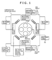
- FIG. 1 is a schematic view of a composite type deposition device for depositing a hard film in accordance with the present invention.
- the hard film in accordance with a first embodiment of the present invention can be formed on each surface of plastic working dies made of iron base alloys (e.g., HSS, SKD11, and SKD61) such as cemented carbides, cermets, high-speed tool steels, specifically, jigs suchas dies for cold stamping, dies for punching , and forging dies, and cutting tools such as tips, drills, and end mills (below, these jigs and cutting tools will be simply generically referred to as "film-formedproducts") .
- the hard film in accordance with the present invention includes Cr in a large amount.
- the hard film in accordance with the first embodiment is a film including a compound including Ti, Cr, Al, and at least one of Si and Y, and the balance of N as essential elements, and including or not including B and C as given elements.
- Ti and Cr are essential for enhancing the hardness of the hard film.
- a high Ti content results in an increase in coefficient of friction with respect to an iron base material which is an object to be worked, which leads to an inferior wear resistance. Therefore, the Ti content is set at less than 0.3 by atomic ratio. Whereas, when the Ti content is too low, the hardness of the hard film cannot be increased. Therefore, the Ti content is set at 0.1 to more by atomic ratio.
- Cr has an effect of improving the sliding property with respect to the iron base material which is an object to be worked, and hence is required to be included in a content of more than 0.3 by atomic ratio.
- a content of 0.6 or more results in relatively lower contents of other elements, resulting in a reduction of the wear resistance.
- the more preferable Cr content is 0.3 to 0.5 by atomic ratio.
- Al, Si, and Y form a dense oxide film excellent in protective property at high temperatures (within the range of generally 800 °C or more), and hence improve the oxidation resistance and the wear resistance at high temperatures.
- high temperatures within the range of generally 800 °C or more
- the oxide film is not sufficiently formed. For this reason, a high content of these elements rather results in a loss of the wear resistance.
- the Al content was set at less than 0.35 by atomic ratio.
- Al has actions of not only enhancing the oxidation resistance, but also enhancing the hardness of the hard film by being incorporated in solid solution into the (Ti, Cr) N crystal.
- the Al content is less than 0.2 by atomic ratio, the hardness of suchahard filmcannot be enhanced, resulting in a reduction of the wear resistance.
- the more preferable Al content is 0.25 to 0.3 by atomic ratio.
- the wear resistance is reduced.
- the content thereof is set at less than 0.1 by atomic ratio.
- the content thereof is more preferably 0.05 or less.
- addition of trace amounts of them results in refinement of crystal grains of the hard film. This allows enhancement of the hardness of the hard film. For this reason, the content thereof is set at 0.01 or more by atomic ratio.
- the hard film of the present invention basically includes a nitride with the composition.
- addition of at least one of B and C in a content of 0.1 or less by atomic ratio as a non-metal element can reduce the coefficient of friction. This enables the improvement of the sliding property.
- the content of at least one of B and C exceeds 0.1 by atomic ratio, on the contrary, the hard film is softened, resulting in a loss of the wear resistance.
- the hard film in accordance with the second embodiment is roughly the same as the hard film in accordance with the first embodiment, but is different from the hard film in accordance with the first embodiment in that it includes M in a content within the range of 0.01 ⁇ e ⁇ 0.1 by atomic ratio as an essential element of a metal element as described above. Therefore, for the hard film in accordance with the second embodiment, only such a different point will be described. For other elements, the description of the hard film in accordance with the first embodiment will be quoted.
- the hard film in accordance with the second embodiment includes, as the M , at least one of the group 4 elements (except for Ti), the group 5 elements, the group 6 elements (except for Cr), and rare earth elements, in an amount of 0.01 or more and 0. 1 or less by atomic ratio.
- the lattice distortion is induced, so that a nitride with a different lattice constant from that of general TiN, CrN, or A1N can be formed.
- the hard film in accordance with the second embodiment can be a still harder film than the hard film in accordance with the first embodiment.
- rare earth elements mention may be made of Sc, Y, La, Ce, Pr, Nd, Pm, Sm, Eu, Gd, Tb, Dy, Ho, Er, Tm, Yb, and Lu.
- these may be included therein alone, or in mixture thereof. When these are included therein in mixture, a so-called misch metal can also be used.
- the M content is set at 0.01 or more and 0.1 or less, and more preferably 0.05 or less by atomic ratio.
- the hard film in accordance with the first embodiment and the hard film in accordance with the second embodiment described up to this point are each preferably formed on the surface of a plastic working die for use in plastic working such as cold stamping or punching, whose temperature during working is not a high temperature, and which does not extremely require the oxidation resistance of the hard film.
- the preheat temperature (i.e., working temperature) prior to working of a to-be-worked object is 600 °C or less, more preferably 500 °C or less, further preferably 400 °C or less, still further preferably 300 °C or less, and most preferably room temperature. Particularly, a description will be given thereto in the item of Examples described later.
- deposition can be carried out by means of a composite type deposition device having a cathode discharge type arc-type evaporation source shown in FIG. 1 .
- a composite type deposition device having a cathode discharge type arc-type evaporation source shown in FIG. 1 .
- a hard film with a film thickness of, for example, 5 ⁇ m can be formed on the surface of a film-formed product in the following manner.
- a film-formed product such as a plastic working die is mounted on a support on a rotating substrate stage. The inside of the chamber is brought into the vacuum state.
- the temperature of the film-formed product is heated to about 400 °C by a heater present in the chamber.
- sputter cleaning is performed using Ar ions.
- a target for a hard film having a desirable composition is mounted on a cathode.
- a 150-A arc current and a -50-V bias voltage are applied.
- the method for forming the hard film in accordance with the first embodiment or the hard film in accordance with the second embodiment on a film-formed product such as a plastic working die is not limited thereto.
- the target includes the metal elements necessary for the formation of the hard film in accordance with the first embodiment in a specific composition. For this reason, only by depositing a film on the surface of a film-formed product with the method using the target for a hard film, it is possible to form the hard film in accordance with the first embodiment.
- the target includes the metal elements necessary for the formation of the hard film in accordance with the second embodiment in a specific composition. For this reason, only by depositing a film on the surface of a film-formed product with the method using the target for a hard film, it is possible to preferably form the hard film in accordance with the second embodiment.
- the targets for a hard film may further include B in composition thereof.
- a B-containing hard film is formed on the surface of a film-formed product. This can result in a still lower coefficient of friction than that of a hard film not including B.
- the target for a hard film can provide a hard film having a still better sliding property and a more excellent wear resistance than those of the hard film not including B.
- the target for a hard film described up to this point is desirably configured to have, for example, about 100-mm dia size because of ease of use in the method. However, it is naturally understood that the size of the target is not limited to this size.
- plastic working die including the hard film in accordance with the first embodiment or the hard film in accordance with the second embodiment formed on the surface in this manner it is possible to preferably perform a plastic working method for performing plastic working of an iron base material.
- a plastic working die including the hard film formed thereon has an excellent wear resistance. This not only can prolong the life of the die, but also can reduce the formation of wear particles. This reduces the possibility of damaging the iron base material which is an object to be worked, which can further reduce the maintenance such as removal of resulting wear particles. Therefore, it is possible to improve the yield of product manufacturing.
- plastic working with the plastic working method is desirably carried out at 600 °C or less, more preferably 500 °C or less, further preferably 400°C or less, still further preferably 300 °C or less, and most preferably at room temperature. This is because too high temperature results in a reduction of the wear resistance.
- hard films with compositions shown in Nos. 1 to 34 of Table 1 below, and Nos. 35 to 50 shown in Table 2 below were formed.
- Table 2 Nos. 33 and 34 shown in Table 1 are shown together for reference.
- a substrate for forming a hard film thereon a mirror-polished cemented carbide substrate was used when the composition and the hardness of the hard film were measured; and a SKD11 substrate (hardness: HRC60) was used when a sliding test was performed.
- the base material was introduced into the chamber of the composite type deposition device, and the inside of the chamber was evacuated (evacuated to 1 ⁇ 10 -3 Pa or less) . Then, the substrate was heated up to about 400 °C. Thereafter, sputter cleaning was carried out with Ar ions. Then, using a 100 mm-dia target, deposition was carried out at an arc current of 150 A, in an atmosphere of N 2 or a mixed gas of N 2 + CH 4 with a total pressure of 4 Pa. The bias to be applied to the substrate was -50 V. Each film thickness of all the hard films was set at 5 ⁇ m.
- compositions of the metal elements (including B) of targets for forming the hard films of Nos. 1 to 34 of Table 1 and Nos. 35 to 50 of Table 2 are the same as the compositions (atomic ratio) of their respective hard films shown in Tables 1 and 2.
- the hardness test of the hard film was performed. Further, a sliding test with an iron base material as a counter part was carried out to examine the wear resistance. At this step, the composition of the hard film was measured by means of an X-ray microanalysisr (electron probe microanalyser; EPMA). The hardness of the hard film was measured under the conditions of a measurement load of 0.25 N and a measurement time of 15 seconds by means of a micro-Vickers hardness tester. The sliding test was performed under the following conditions:
- Tables 1 and 2 there are shown, together with the compositions (atomic ratio) of the hard films each formed on the substrate, the hardness [HV] by the micro-vickers hardness tester, and the wear depth [ ⁇ m] by the sliding test performed at room temperature. Further, in Table 3, there is shown the wear depth when the test temperature was set at room temperature, 400 °C, or 600 °C for the hard film having the composition shown in No. 6 of Table 1 (each as No. 6, No. 6 (400) , or No. 6 (600) ). Incidentally, in Tables 1 to 3, the sample showing a wear depth by the sliding test of 4 ⁇ m or less was judged as favorable. Further, each underline in Tables 1 to 3 indicates that the value departs from the requirement of the present invention.
- each wear depth was 4 ⁇ m or less.
- the wear depth was deeper than 4 ⁇ m.
- the atomic ratio of Ti was less than 0.1
- the atomic ratio of Al was 0.35 or more
- the atomic ratio of L (Si) was 0.1 or more. Therefore, the wear depth was deeper than 4 ⁇ m.
- the atomic ratio of L (Si+Y) was less than 0.01. Therefore, the wear depth was deeper than 4 ⁇ m.
- the atomic ratio of L (Si) was 0.1 or more.
- the wear depth was deeper than 4 ⁇ m.
- the atomic ratio of Al was less than 0.2. Therefore, the wear depth was deeper than 4 ⁇ m.
- the atomic ratio of Al was 0.35 or more. Therefore, the wear depth was deeper than 4 ⁇ m.
- the atomic ratio of Ti was 0.3 or more, and the atomic ratio of Al was 0.3 or less. Therefore, the wear depth was deeper than 4 ⁇ m.
- the atomic ratio of Cr was 0.6 or more. Therefore, the wear depth was deeper than 4 ⁇ m.
- the atomic ratio of Ti was less than 0.1. Therefore, the wear depth was deeper than 4 ⁇ m.
- the atomic ratio of Ti was 0.3 or more. Therefore, the wear depth was deeper than 4 ⁇ m.
- the atomic ratio of L (Si) was 0.1 or more. Therefore, the wear depth was deeper than 4 ⁇ m.
- the atomic ratio of L (Si+Y) was 0.1 or more. Therefore, the wear depth was deeper than 4 ⁇ m.
- the atomic ratio of B was more than 0.1. Therefore, the wear depth was deeper than 4 ⁇ m.
- the atomic ratio of C was more than 0.1, and the atomic ratio of N was less than 0.8. Therefore, the wear depth was deeper than 4 ⁇ m.
- each hard film included, as the element M, at least one of the group 4 elements (except for Ti), the group 5 elements, the group 6 elements (except for Cr), and rare earth elements. Therefore, each hard film tended to have a higher hardness than those of Nos. 4 to 7, 10, 13 to 15, 18, 19, 21 to 23, 25, 26, 28, 30, and 32 shown in Table 1.
- the wear depth was deeper than 4 ⁇ m.
- the atomic ratio of the element M satisfied the requirements of the present invention.
- the atomic ratio of Cr was 0.6 or more. Therefore, the wear depth was deeper than 4 ⁇ m.
- the atomic ratio of the element M satisfied the requirements of the present invention.
- the atomic ratio of Al was less than 0.2, and the atomic ratio of L (Si) was 0.1 or more. Therefore, the wear depth was deeper than 4 ⁇ m.
- the atomic ratio of the element M satisfied the requirements of the present invention.
- the atomic ratio of Al was 0. 35 or more. Therefore, the wear depth was deeper than 4 ⁇ m.
- Nos. 6, 6 (400) , and 6 (600) shown in Table 3 were hard films satisfying the requirements of the present invention. Therefore, the wear depth was 4 ⁇ m or less in any of the cases where the test temperatures of the sliding test were room temperature, 400 °C, and 600 °C. However, for No. 6 (400) , the test temperature of the sliding test was 400 °C, and for No. 6 (600) , the test temperature of the sliding test was 600 °C. Therefore, the wear depth was deeper as compared with No. 6 for which the test temperature of the sliding test was room temperature. However, in both cases, the wear depth was not deeper than 4 ⁇ m.
- the results indicate as follows: when the sliding test is performed at a sliding temperature of 400 °C or less, the wear depth becomes less likely to be larger than in the case where the sliding test is performed at 600 °C; in other words, the excellent wear resistance can be kept.
- Nos. 33 (400) and 34 (400) shown in Table 3 were hard films of different type from that of the present invention.
- the test temperature of the sliding test was as high as 400 °C. Therefore, the wear depth was deeper than 4 ⁇ m.
Landscapes
- Chemical & Material Sciences (AREA)
- Engineering & Computer Science (AREA)
- Organic Chemistry (AREA)
- Materials Engineering (AREA)
- Mechanical Engineering (AREA)
- Metallurgy (AREA)
- Chemical Kinetics & Catalysis (AREA)
- Ceramic Engineering (AREA)
- Manufacturing & Machinery (AREA)
- Structural Engineering (AREA)
- Inorganic Chemistry (AREA)
- Physical Vapour Deposition (AREA)
- Mounting, Exchange, And Manufacturing Of Dies (AREA)
Abstract
Description
- The present invention relates to a hard film to be formed on the surface of a film-formed product such as a jig or a cutting tool, a plastic working die including the hard film formed therein, a plastic working method using a plastic working die including the hard film formed therein, and a target for a hard film which is for forming the hard film,
- Conventionally, plastic working dies using a cemented carbide, a cermet, a high-speed tool steel, or the like as the base material, specifically, jigs such as dies for cold stamping, dies for punching, and forging dies, and cutting tools such as tips, drills, and end mills are each required to have excellent wear resistance and sliding characteristics. For this reason, a hard film is formed on each surface thereof.
- For example, in
JP-A-2002-371352
Whereas, for example, inJP-A-2008-207219 - However, the carbide films which are the technologies described in
JP-A-2002-371352 JP-A-2008-207219 - The present invention was completed in view of the foregoing problem. It is therefore an object of the present invention to provide a hard film excellent in wear resistance, a plastic working die including the hard film formed therein, a plastic working method using a plastic working die including the hard film formed therein, and a target for a hard film which is for forming the hard film.
- [1] A hard film in accordance with one aspect of the present invention, includes (TiaCrbAlcLd) (BxCyNz) in terms of composition, in which the L is at least one of Si and Y, and the a, b, c, d, x, y, and z each denote the atomic ratio, and satisfy: 0.1≤a<0.3; 0.3<b<0.6; 0.2≤c<0.35; 0.01≤d<0.1; a+b+c+d=1; x≤0.1; y≤0.1; 0.8≤z≤1; and x+y+z=1.
- Thus, the hard film in accordance with the present invention includes a nitride of metal elements of Ti, Cr, Al, and L (at least one of Si and Y) in the specific composition ratio. As a result, while the oxide film formed on the surface of the plastic working die is densified, the oxidation resistance and the film hardness can be enhanced. Further, the coefficient of friction can be prevented from increasing. Accordingly, the hard film can acquire an excellent wear resistance. Whereas, inclusion of at least one of B and C as a non-metal element in the specific composition ratio results in a lower coefficient of friction. Accordingly, the hard film is improved in sliding property, and hence, can acquire a more excellent wear resistance.
- [2] Then, a hard film in accordance with another aspect of the present invention, includes (TiaCrbAlcLdMe) (BxCyNz) in terms of composition, in which the L is at least one of Si and Y, the M is at least one of the group 4 elements (except for Ti), the group 5 elements, the group 6 elements (except for Cr), and rare earth elements, and the a, b, c, d, e, x, y, and z each denote the atomic ratio, and satisfy: 0.1≤a<0.3; 0.3<b<0.6; 0.2≤c<0.35;
0.01≤d<0.1; 0.01≤e≤0.1; a+b+c+d+e=1; x≤0.1; y≤0.1; 0.8≤z≤1; and x+y+z=1. - Thus, the hard film in accordance with the present invention includes a nitride of Ti, Cr, Al, and L (at least one of Si and Y), and M (at least one of the group 4 elements (except for Ti), the group 5 elements, and the group 6 elements (except for Cr), and rare earth elements) in the specific composition ratio. As a result, the hard film can be more enhanced in hardness than the hard film of the item [1]. Accordingly, the hard film can acquire a still more excellent wear resistance. Whereas, inclusion of at least one of B and C as a non-metal element in the specific composition ratio results in a lower coefficient of friction. Accordingly, the hard film is improved in sliding property, and hence, can acquire a more excellent wear resistance.
- [3] The hard film according to the item [1] or [2] is preferably formed on the surface of a die for plastic working performed at a temperature of 600 °C or less. With this configuration, the hard film can keep the excellent wear resistance.
- [4] A plastic working die in accordance with one aspect of the present invention is a plastic working die including a hard film formed on the surface, and is characterized in that the hard film is the hard film according to the item [1] or [2] . With this configuration, when the hard film is formed on the surface of the die, it is possible to implement a plastic working die having an excellent wear resistance.
- [5] For the plastic working die according to the item [4], the plastic working die is preferably a die for cold stamping or a die for punching. With this configuration, it is possible to implement a die for cold stamping or a die for punching having an excellent wear resistance.
- [6] A plastic working method in accordance with one aspect of the present invention is a plastic working method for performing plastic working of an iron based material. The method includes: performing the plastic working using a plastic working die including the hard film according to the item [1] or [2] formed therein. With this method, the plastic working die for use in plastic working has an excellent wear resistance, and hence can preferably perform plastic working of an iron based material.
- [7] For the plastic working method according to the item [6], the plastic working is preferably performed at a temperature of 600 °C or less. With this method, the plastic working die for use in plastic working has an excellent wear resistance. Further, the temperature during working is low. Therefore, plastic working of an iron base material can be more preferably performed.
- [8] A target for a hard film in accordance with one aspect of the present invention is a target for a hard film to be used for forming the hard film according to the item [1] or [2] . The target includes (TiaCrbAlcLd) in terms of composition, in which the L is at least one of Si and Y, and the a, b, c, and d each denote the atomic ratio, and satisfy: 0.1≤a<0.3; 0.3<b<0.6; 0.2≤c<0.35; 0.01≤d<0.1; and a+b+c+d=1. Alternatively, the target includes (TiaCrbAlcLdMe) in terms of composition, in which the L is at least one of Si and Y, the M is at least one of the group 4 elements (except for Ti), the group 5 elements, the group 6 elements (except for Cr), and rare earth elements, and the a, b, c, d, and e each denote the atomic ratio, and satisfy: 0.1≤a<0.3; 0.3<b<0.6; 0.2≤c<0.35; 0.01≤d<0.1; 0.01≤e≤0.1; and a+b+c+d+e=1.
- When such a target for a hard film is used, it is possible to form a hard film including a nitride of metal elements of Ti, Cr, Al, and L (at least one of Si and Y) in the specific composition ratio. Accordingly, it is possible to form a hard film having a low coefficient of friction, a favorable sliding property, and an excellent wear resistance.
- [9] It is preferable that the target for a hard film according to the item [8] further includes B. With this configuration, it is possible to form a hard film having a low coefficient of friction, a favorable sliding property, and a more excellent wear resistance.
- The hard film in accordance with the present invention includes specific elements in a specific composition, and hence is excellent in wear resistance. For this reason, by forming such a hard film on the surface of a film-formed product such as a plastic working die, it is possible to improve the wear resistance of the film-formed product.
- The plastic working die in accordance with the present invention includes, a hard f ilmhaving an excellent wear resistance resulting from the inclusion of specific elements therein in a specific composition, formed on the surface, and hence, is excellent in wear resistance. In other words, the plastic working die has an excellent wear resistance. This not only can prolong the life of the die, but also can reduce the formation of wear particles. Accordingly, it is possible to reduce the risk of damaging the iron base material which is an object to be worked. As a result, the product manufacturing yield can be improved. Further, the maintenance such as removal of the formed wear particles can be reduced. Therefore, the productivity can be improved.
- The plastic working method in accordance with the present invention uses a plastic working die including, a hard film having an excellent wear resistance resulting from the inclusion of specific elements therein in a specific composition, formed on the surface, and hence can preferably perform plastic working of an iron base material. In other words, the plastic working die has an excellent wear resistance. This not only can prolong the life of the die, but also can reduce the formation of wear particles. Accordingly, it is possible to reduce the risk of damaging the iron base material which is an object to be worked. As a result, the product manufacturing yield can be improved. Further, the maintenance such as removal of the formed wear particles can be reduced. Therefore, the productivity can be improved.
- The target for a hard film in accordance with the present invention can form a hard film including specific elements therein in a specific composition on the surface of a film-formed product such as a plastic working die. For this reason, the target can impart an excellent wear resistance to the film-formed product.
-
FIG. 1 is a schematic view of a composite type deposition device for depositing a hard film in accordance with the present invention. - Below, a detailed description will be given to a hard film, a plastic working die, a plastic working method, and a target for a hard film in accordance with the present invention.
First, the hard film in accordance with the present invention will be described. - The hard film in accordance with a first embodiment of the present invention can be formed on each surface of plastic working dies made of iron base alloys (e.g., HSS, SKD11, and SKD61) such as cemented carbides, cermets, high-speed tool steels, specifically, jigs suchas dies for cold stamping, dies for punching , and forging dies, and cutting tools such as tips, drills, and end mills (below, these jigs and cutting tools will be simply generically referred to as "film-formedproducts") . As described later, the hard film in accordance with the present invention includes Cr in a large amount. For this reason, when the hard film is formed on each surface thereof, CrN capable of providing excellent adhesion to the ironbase alloy is formed as anunderlayer film. This can further enhance the adhesion between the film-formed product and the hard film, which enables use under higher pressure of contacted surface.
- Then, the hard film in accordance with the first embodiment includes (TiaCrbAlcLd) (BxCyNz) in terms of composition, in which the L is at least one of Si and Y, and the a, b, c, d, x, y, and z each denote the atomic ratio, and satisfy: 0.1≤a<0.3; 0.3≤b<0.6; 0.2≤c<0.35; 0.01≤d<0.1; a+b+c+d=1; x≤0.1; y≤0.1; 0.8≤z≤1; and x+y+z=1.
- In other words, the hard film in accordance with the first embodiment is a film including a compound including Ti, Cr, Al, and at least one of Si and Y, and the balance of N as essential elements, and including or not including B and C as given elements.
- Ti and Cr are essential for enhancing the hardness of the hard film. However, a high Ti content results in an increase in coefficient of friction with respect to an iron base material which is an object to be worked, which leads to an inferior wear resistance. Therefore, the Ti content is set at less than 0.3 by atomic ratio. Whereas, when the Ti content is too low, the hardness of the hard film cannot be increased. Therefore, the Ti content is set at 0.1 to more by atomic ratio.
- Further, Cr has an effect of improving the sliding property with respect to the iron base material which is an object to be worked, and hence is required to be included in a content of more than 0.3 by atomic ratio. However, a content of 0.6 or more results in relatively lower contents of other elements, resulting in a reduction of the wear resistance. The more preferable Cr content is 0.3 to 0.5 by atomic ratio.
- Then, the following fact is known: Al, Si, and Y form a dense oxide film excellent in protective property at high temperatures (within the range of generally 800 °C or more), and hence improve the oxidation resistance and the wear resistance at high temperatures. However, when the increase in temperature due to sliding is not large, or in other cases, the oxide film is not sufficiently formed. For this reason, a high content of these elements rather results in a loss of the wear resistance.
- Therefore, the Al content was set at less than 0.35 by atomic ratio. Incidentally, Al has actions of not only enhancing the oxidation resistance, but also enhancing the hardness of the hard film by being incorporated in solid solution into the (Ti, Cr) N crystal. Thus, when the Al content is less than 0.2 by atomic ratio, the hardness of suchahard filmcannot be enhanced, resulting in a reduction of the wear resistance. The more preferable Al content is 0.25 to 0.3 by atomic ratio.
- Whereas, when Si and Y are included in a content of 0.1 or more by atomic ratio, the wear resistance is reduced. For this reason, the content thereof is set at less than 0.1 by atomic ratio. The content thereof is more preferably 0.05 or less. However, addition of trace amounts of them results in refinement of crystal grains of the hard film. This allows enhancement of the hardness of the hard film. For this reason, the content thereof is set at 0.01 or more by atomic ratio.
- The hard film of the present invention basically includes a nitride with the composition. However, addition of at least one of B and C in a content of 0.1 or less by atomic ratio as a non-metal element can reduce the coefficient of friction. This enables the improvement of the sliding property. When the content of at least one of B and C exceeds 0.1 by atomic ratio, on the contrary, the hard film is softened, resulting in a loss of the wear resistance.
- As described up to this point, by forming the hard film with the composition on the surface of a film-formed product such as a plastic working die, it is possible to improve the wear resistance of the film-formed product.
- A hard film in accordance with a second embodiment includes (TiaCrbAlcLdme) (BxCyNz) in terms of composition, in which the L is at least one of Si and Y, the M is at least one of the group 4 elements (except for Ti), the group 5 elements, the group 6 elements (except for Cr), and rare earth elements, and the a, b, c, d, e, x, y, and z each denote the atomic ratio, and satisfy: 0.1≤a<0.3; 0.3<b<0.6; 0.2≤c<0.35; 0.01≤d<0.1; 0.01≤e≤0.1, a+b+c+d+e=1; x≤0.1; y≤0.1; 0.8≤z≤1; and x+y+z=1.
- Incidentally, the hard film in accordance with the second embodiment is roughly the same as the hard film in accordance with the first embodiment, but is different from the hard film in accordance with the first embodiment in that it includes M in a content within the range of 0.01≤e≤0.1 by atomic ratio as an essential element of a metal element as described above. Therefore, for the hard film in accordance with the second embodiment, only such a different point will be described. For other elements, the description of the hard film in accordance with the first embodiment will be quoted.
- The hard film in accordance with the second embodiment includes, as the M , at least one of the group 4 elements (except for Ti), the group 5 elements, the group 6 elements (except for Cr), and rare earth elements, in an amount of 0.01 or more and 0. 1 or less by atomic ratio. As a result, the lattice distortion is induced, so that a nitride with a different lattice constant from that of general TiN, CrN, or A1N can be formed. For this reason, it is possible to achieve a further enhancement of the hardness of the hard film. In other words, the hard film in accordance with the second embodiment can be a still harder film than the hard film in accordance with the first embodiment. Incidentally, as the rare earth elements, mention may be made of Sc, Y, La, Ce, Pr, Nd, Pm, Sm, Eu, Gd, Tb, Dy, Ho, Er, Tm, Yb, and Lu. As the rare earth elements, these may be included therein alone, or in mixture thereof. When these are included therein in mixture, a so-called misch metal can also be used.
- When the M content is too small, it is not possible to form a still harder film than the hard film in accordance with the first embodiment. Whereas, when the M content is too large, the film becomes brittle, resulting in a reduction of the wear resistance. Therefore, the M content is set at 0.01 or more and 0.1 or less, and more preferably 0.05 or less by atomic ratio.
- The hard film in accordance with the first embodiment and the hard film in accordance with the second embodiment described up to this point are each preferably formed on the surface of a plastic working die for use in plastic working such as cold stamping or punching, whose temperature during working is not a high temperature, and which does not extremely require the oxidation resistance of the hard film.
As a guideline of the operating temperature of the plastic working die including the hard film in accordance with the first embodiment or the hard film in accordance with the second embodiment formed on the surface, the preheat temperature (i.e., working temperature) prior to working of a to-be-worked object is 600 °C or less, more preferably 500 °C or less, further preferably 400 °C or less, still further preferably 300 °C or less, and most preferably room temperature. Particularly, a description will be given thereto in the item of Examples described later. - As a method for forming the hard film in accordance with the first embodiment or the hard film in accordance with the second embodiment on the film-formed product such as a plastic working die, the following may be mentioned.
For example, deposition can be carried out by means of a composite type deposition device having a cathode discharge type arc-type evaporation source shown inFIG. 1 . With such a composite type deposition device, a hard film with a film thickness of, for example, 5 µm can be formed on the surface of a film-formed product in the following manner. On a support on a rotating substrate stage, a film-formed product such as a plastic working die is mounted. The inside of the chamber is brought into the vacuum state. Then, the temperature of the film-formed product is heated to about 400 °C by a heater present in the chamber. Thus, sputter cleaning is performed using Ar ions. Then, a target for a hard film having a desirable composition is mounted on a cathode. Thus, in a N2 gas or in a mixture gas of N2 and CH4 with a total pressure of 4 Pa, for example, a 150-A arc current and a -50-V bias voltage are applied.
Incidentally, the method for forming the hard film in accordance with the first embodiment or the hard film in accordance with the second embodiment on a film-formed product such as a plastic working die is not limited thereto. There can also be used an arc ion plating method, an unbalanced magnetron sputtering method, or the like commonly used as a deposition technology. - The target for a hard film includes (TiaCrbAlcLd) in terms of composition, in which the L is at least one of Si and Y, and the a, b, c, and d each denote the atomic ratio, and satisfy: 0.1≤a<0.3; 0.3<b<0.6; 0.2≤c<0.35; 0.01≤d<0.1; and a+b+c+d=1. In this case, the target includes the metal elements necessary for the formation of the hard film in accordance with the first embodiment in a specific composition. For this reason, only by depositing a film on the surface of a film-formed product with the method using the target for a hard film, it is possible to form the hard film in accordance with the first embodiment.
Alternatively, the target for a hard film includes (TiaCrbAlcLdMe) in terms of composition, in which the L is at least one of Si and Y, the M is at least one of the group 4 elements (except for Ti), the group 5 elements, the group 6 elements (except for Cr), and rare earth elements, and the a, b, c, d, and e each denote the atomic ratio, and satisfy: 0.1≤a<0.3; 0.3<b<0.6; 0.2≤c<0.35; 0.01≤d<0.1; 0.01≤e≤0.1; and a+b+c+d+e=1. In this case, the target includes the metal elements necessary for the formation of the hard film in accordance with the second embodiment in a specific composition. For this reason, only by depositing a film on the surface of a film-formed product with the method using the target for a hard film, it is possible to preferably form the hard film in accordance with the second embodiment. - The targets for a hard film may further include B in composition thereof. With this composition, a B-containing hard film is formed on the surface of a film-formed product. This can result in a still lower coefficient of friction than that of a hard film not including B. In other words, the target for a hard film can provide a hard film having a still better sliding property and a more excellent wear resistance than those of the hard film not including B.
- The target for a hard film described up to this point is desirably configured to have, for example, about 100-mm dia size because of ease of use in the method. However, it is naturally understood that the size of the target is not limited to this size.
- Thus, by using the plastic working die including the hard film in accordance with the first embodiment or the hard film in accordance with the second embodiment formed on the surface in this manner, it is possible to preferably perform a plastic working method for performing plastic working of an iron base material. Such a plastic working die including the hard film formed thereon has an excellent wear resistance. This not only can prolong the life of the die, but also can reduce the formation of wear particles. This reduces the possibility of damaging the iron base material which is an object to be worked, which can further reduce the maintenance such as removal of resulting wear particles. Therefore, it is possible to improve the yield of product manufacturing.
- As described above, in view of the characteristics of the hard film, plastic working with the plastic working method is desirably carried out at 600 °C or less, more preferably 500 °C or less, further preferably 400°C or less, still further preferably 300 °C or less, and most preferably at room temperature. This is because too high temperature results in a reduction of the wear resistance.
- Below, Examples satisfying the requirements of the present invention and Comparative Examples not satisfying the requirements will be more specifically described by way of comparison therebetween.
- Using a composite type deposition device having a cathode discharge type arc-type evaporation source, hard films with compositions shown in Nos. 1 to 34 of Table 1 below, and Nos. 35 to 50 shown in Table 2 below were formed. Incidentally, in Table 2, Nos. 33 and 34 shown in Table 1 are shown together for reference.
Herein, as a substrate for forming a hard film thereon, a mirror-polished cemented carbide substrate was used when the composition and the hardness of the hard film were measured; and a SKD11 substrate (hardness: HRC60) was used when a sliding test was performed. In any case of forming either hard film, the base material was introduced into the chamber of the composite type deposition device, and the inside of the chamber was evacuated (evacuated to 1 × 10⁻³ Pa or less) . Then, the substrate was heated up to about 400 °C. Thereafter, sputter cleaning was carried out with Ar ions. Then, using a 100 mm-dia target, deposition was carried out at an arc current of 150 A, in an atmosphere of N2 or a mixed gas of N2 + CH4 with a total pressure of 4 Pa. The bias to be applied to the substrate was -50 V. Each film thickness of all the hard films was set at 5 µm. Incidentally, the compositions of the metal elements (including B) of targets for forming the hard films of Nos. 1 to 34 of Table 1 and Nos. 35 to 50 of Table 2 are the same as the compositions (atomic ratio) of their respective hard films shown in Tables 1 and 2. - For the substrates each including the hard film thus formed thereon, the hardness test of the hard film was performed. Further, a sliding test with an iron base material as a counter part was carried out to examine the wear resistance. At this step, the composition of the hard film was measured by means of an X-ray microanalyser (electron probe microanalyser; EPMA).
The hardness of the hard film was measured under the conditions of a measurement load of 0.25 N and a measurement time of 15 seconds by means of a micro-Vickers hardness tester.
The sliding test was performed under the following conditions: -
- Device: Vane-on-disk type sliding tester
- Vane: High tensile strength steel sheet pin (tensile strength 590 MPa)
- Disk: SKD11 steel (HRC60) with a film formed thereon
- Sliding speed: 0.2 m/sec
- Load: 500 N
- Sliding distance: 2000 m
- Test temperature: roomtemperature (without heating), 400 °C, 600 °C
- Evaluation item: Wear depth of the sliding portion (mean at four sites)
- In Tables 1 and 2, there are shown, together with the compositions (atomic ratio) of the hard films each formed on the substrate, the hardness [HV] by the micro-vickers hardness tester, and the wear depth [µm] by the sliding test performed at room temperature. Further, in Table 3, there is shown the wear depth when the test temperature was set at room temperature, 400 °C, or 600 °C for the hard film having the composition shown in No. 6 of Table 1 (each as No. 6, No. 6(400), or No. 6(600)). Incidentally, in Tables 1 to 3, the sample showing a wear depth by the sliding test of 4 µm or less was judged as favorable. Further, each underline in Tables 1 to 3 indicates that the value departs from the requirement of the present invention.
-


-

-

- For Nos. 4 to 7, 10, 13 to 15, 18, 19, 21 to 23, 25, 26, 28, 30, and 32 shown in Table 1, the composition of each hard film satisfied the requirements of the present invention. Therefore, each wear depth was 4 µm or less.
- In contrast, for No. 1 shown in Table 1, the atomic ratio of Ti was 0.3 or more, the atomic ratio of Cr was 0.3 or less, and the atomic ratio of Al was 0.35 or more. Therefore, the wear depth was deeper than 4 µm.
Whereas, for No. 2 shown in Table 1, the atomic ratio of Ti was less than 0.1, the atomic ratio of Al was 0.35 or more, and the atomic ratio of L (Si) was 0.1 or more. Therefore, the wear depth was deeper than 4 µm.
For No. 3 shown in Table 1, the atomic ratio of L (Si+Y) was less than 0.01. Therefore, the wear depth was deeper than 4 µm.
For No. 8 shown in Table 1, the atomic ratio of L (Si) was 0.1 or more. Therefore, the wear depth was deeper than 4 µm.
For No. 9 shown in Table 1, the atomic ratio of Al was less than 0.2. Therefore, the wear depth was deeper than 4 µm.
For No. 11 shown in Table 1, the atomic ratio of Al was 0.35 or more. Therefore, the wear depth was deeper than 4 µm.
For No. 12 shown in Table 1, the atomic ratio of Ti was 0.3 or more, and the atomic ratio of Al was 0.3 or less. Therefore, the wear depth was deeper than 4 µm.
For No. 16 shown in Table 1, the atomic ratio of Cr was 0.6 or more. Therefore, the wear depth was deeper than 4 µm.
For No. 17 shown in Table 1, the atomic ratio of Ti was less than 0.1. Therefore, the wear depth was deeper than 4 µm.
For No. 20 shown in Table 1, the atomic ratio of Ti was 0.3 or more. Therefore, the wear depth was deeper than 4 µm.
For No. 24 shown in Table 1, the atomic ratio of L (Si) was 0.1 or more. Therefore, the wear depth was deeper than 4 µm.
For No. 27 shown in Table 1, the atomic ratio of L (Si+Y) was 0.1 or more. Therefore, the wear depth was deeper than 4 µm.
For No. 29 shown in Table 1, the atomic ratio of B was more than 0.1. Therefore, the wear depth was deeper than 4 µm.
For No. 31 shown in Table 1, the atomic ratio of C was more than 0.1, and the atomic ratio of N was less than 0.8. Therefore, the wear depth was deeper than 4 µm.
No. 33 shown in Table 1 was a VC film including V in an amount of 0. 5 by atomic ratio, and C in an amount of 0. 5 by atomic ratio. No. 34 was a TiC film including Ti in an amount of 0.5 by atomic ratio, and C in an amount of 0.5 by atomic ratio. In both cases, the films were hard films different in type from those of the present invention. Therefore, the wear depth was deeper than 4 µm. - Whereas, for Nos . 35 to 43 shown in Table 2, the composition of each hard film satisfied the requirements of the present invention. Therefore, the wear depth was 4 µm or less. Further, for Nos. 35 to 43 shown in Table 2, each hard film included, as the element M, at least one of the group 4 elements (except for Ti), the group 5 elements, the group 6 elements (except for Cr), and rare earth elements. Therefore, each hard film tended to have a higher hardness than those of Nos. 4 to 7, 10, 13 to 15, 18, 19, 21 to 23, 25, 26, 28, 30, and 32 shown in Table 1.
- In contrast, for No. 44 shown in Table 2, the atomic ratio of the element M (Sm) exceeded 0.1. Therefore, the wear depth was deeper than 4 µm.
Further, for No. 45 shown in Table 2, the atomic ratio of the element M satisfied the requirements of the present invention. However, the atomic ratio of Ti was less than 0.1. Therefore, the wear depth was deeper than 4 µm.
For No. 46 shown in Table 2, the atomic ratio of the element M satisfied the requirements of the present invention. However, the atomic ratio of Ti was 0.3 or more. Therefore, the wear depth was deeper than 4 µm.
For No. 47 shown in Table 2, the atomic ratio of the element M satisfied the requirements of the present invention. However, the atomic ratio of Cr was 0.3 or less. Therefore, the wear depth was deeper than 4 µm.
For No. 48 shown in Table 2, the atomic ratio of the element M satisfied the requirements of the present invention. However, the atomic ratio of Cr was 0.6 or more. Therefore, the wear depth was deeper than 4 µm.
For No. 49 shown in Table 2, the atomic ratio of the element M satisfied the requirements of the present invention. However, the atomic ratio of Al was less than 0.2, and the atomic ratio of L (Si) was 0.1 or more. Therefore, the wear depth was deeper than 4 µm.
For No. 50 shown in Table 2, the atomic ratio of the element M satisfied the requirements of the present invention. However, the atomic ratio of Al was 0. 35 or more. Therefore, the wear depth was deeper than 4 µm. - Then, Nos. 6, 6(400), and 6(600) shown in Table 3 were hard films satisfying the requirements of the present invention. Therefore, the wear depth was 4 µm or less in any of the cases where the test temperatures of the sliding test were room temperature, 400 °C, and 600 °C. However, for No. 6(400), the test temperature of the sliding test was 400 °C, and for No. 6(600), the test temperature of the sliding test was 600 °C. Therefore, the wear depth was deeper as compared with No. 6 for which the test temperature of the sliding test was room temperature. However, in both cases, the wear depth was not deeper than 4 µm. Further, the results indicate as follows: when the sliding test is performed at a sliding temperature of 400 °C or less, the wear depth becomes less likely to be larger than in the case where the sliding test is performed at 600 °C; in other words, the excellent wear resistance can be kept.
- In contrast, Nos. 33(400) and 34(400) shown in Table 3 were hard films of different type from that of the present invention. The test temperature of the sliding test was as high as 400 °C. Therefore, the wear depth was deeper than 4 µm.
Claims (13)
- A hard film, comprising (TiacrbAlcLd) (BxCyNz) in terms of composition, in which the L is at least one of Si and Y, and the a, b, c, d, x, y, and z each denote the atomic ratio, and satisfy:0.1≤a<0.3;0.3<b<0.6;0.2≤c<0.35;0.01≤d<0.1;a+b+c+d=1;x≤0.1;y≤0.1;0.8≤z≤1; andx+y+z=1.
- A hard film, comprising (TiaCrbAlcLdMe) (BxCyNz) in terms of composition, in which the L is at least one of Si and Y, the M is at least one of the group 4 elements (except for Ti), the group 5 elements, the group 6 elements (except for Cr), and rare earth elements, and the a, b, c, d, e, x, y, and z each denote the atomic ratio, and satisfy:0.1≤a<0.3;0.3<b<0.6;0.2≤c<0.35;0.01≤d<0.1;0.01≤e≤0.1;a+b+c+d+e=1;x≤0.1;y≤0.1;0.8≤z≤1; andx+y+z=1.
- The hard film according to claim 1, to be formed on the surface of a die for plastic working performed at a temperature of 600 °C or less.
- The hard film according to claim 2, to be formed on the surface of a die for plastic working performed at a temperature of 600 °C or less.
- A plastic working die comprising a hard film formed on the surface,
the hard film being the hard film according to claim 1. - A plastic working die comprising a hard film formed on the surface,
the hard film being the hard film according to claim 2. - The plastic working die according to claim 5 or 6, the plastic working die being a die for cold stamping or a die for punching.
- A plastic working method for performing plastic working of an iron based material,
the method, comprising: performing the plastic working using a plastic working die including the hard film according to claim 1 formed therein. - Aplastic working method for performing plastic working of an iron based material,
the method, comprising: performing the plastic working using a plastic working die including the hard film according to claim 2 formed therein. - The plastic working method according to claim 8 or 9, wherein the plastic working is performed at a temperature of 600 °C or less.
- A target for a hard film to be used for forming the hard film according to claim 1,
the target comprising (TiacrbAlcLd) in terms of composition, in which the L is at least one of Si and Y, and the a, b, c, and d each denote the atomic ratio, and satisfy:0.1≤a<0.3;0.3<b<0.6;0.2≤c<0.35;0.01≤d<0.1; anda+b+c+d=1. - A target for a hard film to be used for forming the hard film according to claim 2,
the target comprising (TiaCrbAlcLdMe) in terms of composition, in which the L is at least one of Si and Y, the M is at least one of the group 4 elements (except for Ti), the group 5 elements, the group 6 elements (except for Cr), and rare earth elements, and the a, b, c, d, and e each denote the atomic ratio, and satisfy:0.1≤a<0.3;0.3<b<0.6;0.2≤c<0.35;0.01≤d<0.1;0.01≤e≤0.1; anda+b+c+d+e=1. - The target for a hard film according to claim 11 or 12, further comprising B.
Applications Claiming Priority (1)
| Application Number | Priority Date | Filing Date | Title |
|---|---|---|---|
| JP2009230936A JP5193153B2 (en) | 2009-10-02 | 2009-10-02 | Hard coating, mold for plastic working, plastic working method, and target for hard coating |
Publications (2)
| Publication Number | Publication Date |
|---|---|
| EP2316984A1 true EP2316984A1 (en) | 2011-05-04 |
| EP2316984B1 EP2316984B1 (en) | 2015-03-18 |
Family
ID=43736183
Family Applications (1)
| Application Number | Title | Priority Date | Filing Date |
|---|---|---|---|
| EP10009513.2A Not-in-force EP2316984B1 (en) | 2009-10-02 | 2010-09-13 | Hard film, plastic working die, plastic working method, and target for hard film |
Country Status (3)
| Country | Link |
|---|---|
| US (2) | US8475941B2 (en) |
| EP (1) | EP2316984B1 (en) |
| JP (1) | JP5193153B2 (en) |
Families Citing this family (4)
| Publication number | Priority date | Publication date | Assignee | Title |
|---|---|---|---|---|
| TW201321542A (en) * | 2011-11-29 | 2013-06-01 | Chenming Mold Ind Corp | Device for making IC shielding film coating and metal shielding film of IC |
| JP6267604B2 (en) | 2014-03-03 | 2018-01-24 | 株式会社神戸製鋼所 | Hard coating, method for forming the same, and die for hot forming of steel sheet |
| CN103981487B (en) * | 2014-05-28 | 2016-04-27 | 厦门建霖工业有限公司 | A kind of chromium-aluminum alloy target material its preparation method and application |
| JP7372002B1 (en) | 2022-02-15 | 2023-10-31 | Seavac株式会社 | hard coating |
Citations (4)
| Publication number | Priority date | Publication date | Assignee | Title |
|---|---|---|---|---|
| JP2002371352A (en) | 2001-06-15 | 2002-12-26 | Yuken Industry Co Ltd | Method for forming vanadium-based coating |
| US20080038503A1 (en) * | 2006-08-09 | 2008-02-14 | Kabushiki Kaisha Kobe Seiko Sho (Kobe Steel, Ltd.) | Hard film and hard film-coated material |
| EP1947209A1 (en) * | 2007-01-17 | 2008-07-23 | Kabushiki Kaisha Kobe Seiko Sho | Hard coating film for forming tool and forming tool |
| JP2008207219A (en) | 2007-02-27 | 2008-09-11 | Toyo Advanced Technologies Co Ltd | Pressing die |
Family Cites Families (16)
| Publication number | Priority date | Publication date | Assignee | Title |
|---|---|---|---|---|
| JPS5928915B2 (en) * | 1979-07-04 | 1984-07-17 | 日本電気ホームエレクトロニクス株式会社 | cathode ray tube display device |
| DE19818782A1 (en) * | 1998-04-27 | 1999-10-28 | Muenz Wolf Dieter | Coated high speed steel, hard metal and cermet tools |
| JP4112836B2 (en) * | 2001-06-19 | 2008-07-02 | 株式会社神戸製鋼所 | Target for forming hard coatings for cutting tools |
| ATE343659T1 (en) * | 2000-12-28 | 2006-11-15 | Kobe Steel Ltd | HARD MATERIAL LAYER FOR CUTTING TOOLS |
| JP5060714B2 (en) * | 2004-09-30 | 2012-10-31 | 株式会社神戸製鋼所 | Hard coating excellent in wear resistance and oxidation resistance, and target for forming the hard coating |
| US7348074B2 (en) * | 2005-04-01 | 2008-03-25 | Oc Oerlikon Balzers Ag | Multilayer hard coating for tools |
| US7537822B2 (en) * | 2005-05-26 | 2009-05-26 | Hitachi Tool Engineering, Ltd. | Hard-coated member |
| JP2007136597A (en) * | 2005-11-17 | 2007-06-07 | Tungaloy Corp | Coating member |
| JP2007185739A (en) * | 2006-01-12 | 2007-07-26 | Mitsubishi Materials Corp | Cutting tool made of surface-coated cemented carbide that exhibits excellent wear resistance with a hard coating layer in high-speed cutting of soft difficult-to-cut materials |
| JP4950499B2 (en) * | 2006-02-03 | 2012-06-13 | 株式会社神戸製鋼所 | Hard coating and method for forming the same |
| JP4967396B2 (en) * | 2006-03-22 | 2012-07-04 | 株式会社タンガロイ | Si-containing composite nitride film and coated cutting tool |
| JP4704970B2 (en) * | 2006-07-19 | 2011-06-22 | 株式会社神戸製鋼所 | Hard film with excellent film removal |
| JP2008105107A (en) * | 2006-10-23 | 2008-05-08 | Mitsubishi Materials Corp | Surface coated cutting tool with excellent wear resistance with hard coating layer in high speed cutting |
| SE0602814L (en) * | 2006-12-27 | 2008-06-28 | Sandvik Intellectual Property | Cutting tool with multilayer coating |
| JP5234926B2 (en) * | 2008-04-24 | 2013-07-10 | 株式会社神戸製鋼所 | Hard film and hard film forming target |
| JP2010168638A (en) * | 2009-01-26 | 2010-08-05 | Kobe Steel Ltd | Hard film-coated member and fixing tool for molding |
-
2009
- 2009-10-02 JP JP2009230936A patent/JP5193153B2/en not_active Expired - Fee Related
-
2010
- 2010-09-13 EP EP10009513.2A patent/EP2316984B1/en not_active Not-in-force
- 2010-09-15 US US12/882,565 patent/US8475941B2/en not_active Expired - Fee Related
-
2013
- 2013-05-29 US US13/904,115 patent/US8741114B2/en not_active Expired - Fee Related
Patent Citations (4)
| Publication number | Priority date | Publication date | Assignee | Title |
|---|---|---|---|---|
| JP2002371352A (en) | 2001-06-15 | 2002-12-26 | Yuken Industry Co Ltd | Method for forming vanadium-based coating |
| US20080038503A1 (en) * | 2006-08-09 | 2008-02-14 | Kabushiki Kaisha Kobe Seiko Sho (Kobe Steel, Ltd.) | Hard film and hard film-coated material |
| EP1947209A1 (en) * | 2007-01-17 | 2008-07-23 | Kabushiki Kaisha Kobe Seiko Sho | Hard coating film for forming tool and forming tool |
| JP2008207219A (en) | 2007-02-27 | 2008-09-11 | Toyo Advanced Technologies Co Ltd | Pressing die |
Also Published As
| Publication number | Publication date |
|---|---|
| EP2316984B1 (en) | 2015-03-18 |
| US8475941B2 (en) | 2013-07-02 |
| JP5193153B2 (en) | 2013-05-08 |
| US8741114B2 (en) | 2014-06-03 |
| US20130256130A1 (en) | 2013-10-03 |
| JP2011080101A (en) | 2011-04-21 |
| US20110079069A1 (en) | 2011-04-07 |
Similar Documents
| Publication | Publication Date | Title |
|---|---|---|
| EP1992713B1 (en) | Hard coating excellent in wear resistance and in oxidation resistance and target for forming the same | |
| EP1422311B1 (en) | Hard film and hard film coated tool | |
| EP2443267B1 (en) | Protective coating, a coated member having a protective coating as well as method for producing a protective coating | |
| KR101701186B1 (en) | Cutting tool | |
| EP2138602B1 (en) | Hard coating laminate and method for forming hard coating laminate | |
| JP5438665B2 (en) | Hard film covering member, jig and tool, and target | |
| EP3456867B1 (en) | Coated drill | |
| US8003231B2 (en) | Wear-resistant member with hard coating | |
| US8741114B2 (en) | Hard film, plastic working die, plastic working method, and target for hard film | |
| EP1710032B1 (en) | Cutting tool made of surface-coated super hard alloy, and method for manufacture thereof | |
| JP4357160B2 (en) | Sputtering target, hard coating using the same, and hard film coating member | |
| EP3109341A1 (en) | Hard coating film and method of forming same | |
| JP6603061B2 (en) | Cermet and cutting tools | |
| JP5268771B2 (en) | Method for producing sputtering target, method for forming hard film using the same, and hard film coated member | |
| EP2937439A1 (en) | Hard coating film having excellent adhesion resistance to soft metal | |
| JP2012076156A (en) | Cemented carbide, and method of manufacturing the same | |
| CN120758833B (en) | High-temperature wear-resistant coating cutter and preparation method thereof | |
| JP2002254229A (en) | Drill made of surface-coated cemented carbide and excellent in wear resistance in high speed cutting | |
| JP2002254228A (en) | Drill made of surface-coated cemented carbide and excellent in wear resistance in high speed cutting | |
| EP3951002B1 (en) | V alloy target | |
| JP6882416B2 (en) | Cermet and cutting tools | |
| JP2010168638A (en) | Hard film-coated member and fixing tool for molding | |
| JP2007084910A (en) | Hard coating and its production method | |
| JP2002254236A (en) | End mill made of surface-coated cemented carbide and excellent in wear resistance in high speed cutting | |
| JP2006346835A (en) | Cutting tips made of surface-coated cubic boron nitride-based ultra-high pressure sintered material with excellent wear resistance in high-speed intermittent cutting of high-hardness steel |
Legal Events
| Date | Code | Title | Description |
|---|---|---|---|
| PUAI | Public reference made under article 153(3) epc to a published international application that has entered the european phase |
Free format text: ORIGINAL CODE: 0009012 |
|
| AK | Designated contracting states |
Kind code of ref document: A1 Designated state(s): AL AT BE BG CH CY CZ DE DK EE ES FI FR GB GR HR HU IE IS IT LI LT LU LV MC MK MT NL NO PL PT RO SE SI SK SM TR |
|
| AX | Request for extension of the european patent |
Extension state: BA ME RS |
|
| 17P | Request for examination filed |
Effective date: 20110728 |
|
| GRAP | Despatch of communication of intention to grant a patent |
Free format text: ORIGINAL CODE: EPIDOSNIGR1 |
|
| INTG | Intention to grant announced |
Effective date: 20141105 |
|
| GRAS | Grant fee paid |
Free format text: ORIGINAL CODE: EPIDOSNIGR3 |
|
| GRAA | (expected) grant |
Free format text: ORIGINAL CODE: 0009210 |
|
| AK | Designated contracting states |
Kind code of ref document: B1 Designated state(s): AL AT BE BG CH CY CZ DE DK EE ES FI FR GB GR HR HU IE IS IT LI LT LU LV MC MK MT NL NO PL PT RO SE SI SK SM TR |
|
| REG | Reference to a national code |
Ref country code: GB Ref legal event code: FG4D |
|
| REG | Reference to a national code |
Ref country code: CH Ref legal event code: EP |
|
| REG | Reference to a national code |
Ref country code: IE Ref legal event code: FG4D |
|
| REG | Reference to a national code |
Ref country code: AT Ref legal event code: REF Ref document number: 716639 Country of ref document: AT Kind code of ref document: T Effective date: 20150415 |
|
| REG | Reference to a national code |
Ref country code: DE Ref legal event code: R096 Ref document number: 602010023143 Country of ref document: DE Effective date: 20150430 |
|
| REG | Reference to a national code |
Ref country code: SE Ref legal event code: TRGR |
|
| REG | Reference to a national code |
Ref country code: NL Ref legal event code: VDEP Effective date: 20150318 |
|
| REG | Reference to a national code |
Ref country code: NL Ref legal event code: VDEP Effective date: 20150318 |
|
| PG25 | Lapsed in a contracting state [announced via postgrant information from national office to epo] |
Ref country code: HR Free format text: LAPSE BECAUSE OF FAILURE TO SUBMIT A TRANSLATION OF THE DESCRIPTION OR TO PAY THE FEE WITHIN THE PRESCRIBED TIME-LIMIT Effective date: 20150318 Ref country code: LT Free format text: LAPSE BECAUSE OF FAILURE TO SUBMIT A TRANSLATION OF THE DESCRIPTION OR TO PAY THE FEE WITHIN THE PRESCRIBED TIME-LIMIT Effective date: 20150318 Ref country code: FI Free format text: LAPSE BECAUSE OF FAILURE TO SUBMIT A TRANSLATION OF THE DESCRIPTION OR TO PAY THE FEE WITHIN THE PRESCRIBED TIME-LIMIT Effective date: 20150318 Ref country code: NO Free format text: LAPSE BECAUSE OF FAILURE TO SUBMIT A TRANSLATION OF THE DESCRIPTION OR TO PAY THE FEE WITHIN THE PRESCRIBED TIME-LIMIT Effective date: 20150618 |
|
| REG | Reference to a national code |
Ref country code: AT Ref legal event code: MK05 Ref document number: 716639 Country of ref document: AT Kind code of ref document: T Effective date: 20150318 |
|
| REG | Reference to a national code |
Ref country code: LT Ref legal event code: MG4D |
|
| PG25 | Lapsed in a contracting state [announced via postgrant information from national office to epo] |
Ref country code: LV Free format text: LAPSE BECAUSE OF FAILURE TO SUBMIT A TRANSLATION OF THE DESCRIPTION OR TO PAY THE FEE WITHIN THE PRESCRIBED TIME-LIMIT Effective date: 20150318 Ref country code: GR Free format text: LAPSE BECAUSE OF FAILURE TO SUBMIT A TRANSLATION OF THE DESCRIPTION OR TO PAY THE FEE WITHIN THE PRESCRIBED TIME-LIMIT Effective date: 20150619 |
|
| PG25 | Lapsed in a contracting state [announced via postgrant information from national office to epo] |
Ref country code: NL Free format text: LAPSE BECAUSE OF FAILURE TO SUBMIT A TRANSLATION OF THE DESCRIPTION OR TO PAY THE FEE WITHIN THE PRESCRIBED TIME-LIMIT Effective date: 20150318 |
|
| PG25 | Lapsed in a contracting state [announced via postgrant information from national office to epo] |
Ref country code: SK Free format text: LAPSE BECAUSE OF FAILURE TO SUBMIT A TRANSLATION OF THE DESCRIPTION OR TO PAY THE FEE WITHIN THE PRESCRIBED TIME-LIMIT Effective date: 20150318 Ref country code: EE Free format text: LAPSE BECAUSE OF FAILURE TO SUBMIT A TRANSLATION OF THE DESCRIPTION OR TO PAY THE FEE WITHIN THE PRESCRIBED TIME-LIMIT Effective date: 20150318 Ref country code: RO Free format text: LAPSE BECAUSE OF FAILURE TO SUBMIT A TRANSLATION OF THE DESCRIPTION OR TO PAY THE FEE WITHIN THE PRESCRIBED TIME-LIMIT Effective date: 20150318 Ref country code: ES Free format text: LAPSE BECAUSE OF FAILURE TO SUBMIT A TRANSLATION OF THE DESCRIPTION OR TO PAY THE FEE WITHIN THE PRESCRIBED TIME-LIMIT Effective date: 20150318 Ref country code: PT Free format text: LAPSE BECAUSE OF FAILURE TO SUBMIT A TRANSLATION OF THE DESCRIPTION OR TO PAY THE FEE WITHIN THE PRESCRIBED TIME-LIMIT Effective date: 20150720 Ref country code: CZ Free format text: LAPSE BECAUSE OF FAILURE TO SUBMIT A TRANSLATION OF THE DESCRIPTION OR TO PAY THE FEE WITHIN THE PRESCRIBED TIME-LIMIT Effective date: 20150318 |
|
| PG25 | Lapsed in a contracting state [announced via postgrant information from national office to epo] |
Ref country code: PL Free format text: LAPSE BECAUSE OF FAILURE TO SUBMIT A TRANSLATION OF THE DESCRIPTION OR TO PAY THE FEE WITHIN THE PRESCRIBED TIME-LIMIT Effective date: 20150318 Ref country code: AT Free format text: LAPSE BECAUSE OF FAILURE TO SUBMIT A TRANSLATION OF THE DESCRIPTION OR TO PAY THE FEE WITHIN THE PRESCRIBED TIME-LIMIT Effective date: 20150318 Ref country code: IS Free format text: LAPSE BECAUSE OF FAILURE TO SUBMIT A TRANSLATION OF THE DESCRIPTION OR TO PAY THE FEE WITHIN THE PRESCRIBED TIME-LIMIT Effective date: 20150718 |
|
| REG | Reference to a national code |
Ref country code: DE Ref legal event code: R097 Ref document number: 602010023143 Country of ref document: DE |
|
| PG25 | Lapsed in a contracting state [announced via postgrant information from national office to epo] |
Ref country code: IT Free format text: LAPSE BECAUSE OF FAILURE TO SUBMIT A TRANSLATION OF THE DESCRIPTION OR TO PAY THE FEE WITHIN THE PRESCRIBED TIME-LIMIT Effective date: 20150318 |
|
| PLBE | No opposition filed within time limit |
Free format text: ORIGINAL CODE: 0009261 |
|
| STAA | Information on the status of an ep patent application or granted ep patent |
Free format text: STATUS: NO OPPOSITION FILED WITHIN TIME LIMIT |
|
| PG25 | Lapsed in a contracting state [announced via postgrant information from national office to epo] |
Ref country code: DK Free format text: LAPSE BECAUSE OF FAILURE TO SUBMIT A TRANSLATION OF THE DESCRIPTION OR TO PAY THE FEE WITHIN THE PRESCRIBED TIME-LIMIT Effective date: 20150318 |
|
| 26N | No opposition filed |
Effective date: 20151221 |
|
| PG25 | Lapsed in a contracting state [announced via postgrant information from national office to epo] |
Ref country code: SI Free format text: LAPSE BECAUSE OF FAILURE TO SUBMIT A TRANSLATION OF THE DESCRIPTION OR TO PAY THE FEE WITHIN THE PRESCRIBED TIME-LIMIT Effective date: 20150318 |
|
| PG25 | Lapsed in a contracting state [announced via postgrant information from national office to epo] |
Ref country code: LU Free format text: LAPSE BECAUSE OF FAILURE TO SUBMIT A TRANSLATION OF THE DESCRIPTION OR TO PAY THE FEE WITHIN THE PRESCRIBED TIME-LIMIT Effective date: 20150913 Ref country code: MC Free format text: LAPSE BECAUSE OF FAILURE TO SUBMIT A TRANSLATION OF THE DESCRIPTION OR TO PAY THE FEE WITHIN THE PRESCRIBED TIME-LIMIT Effective date: 20150318 |
|
| REG | Reference to a national code |
Ref country code: CH Ref legal event code: PL |
|
| GBPC | Gb: european patent ceased through non-payment of renewal fee |
Effective date: 20150913 |
|
| REG | Reference to a national code |
Ref country code: IE Ref legal event code: MM4A |
|
| REG | Reference to a national code |
Ref country code: FR Ref legal event code: ST Effective date: 20160531 |
|
| PG25 | Lapsed in a contracting state [announced via postgrant information from national office to epo] |
Ref country code: IE Free format text: LAPSE BECAUSE OF NON-PAYMENT OF DUE FEES Effective date: 20150913 Ref country code: CH Free format text: LAPSE BECAUSE OF NON-PAYMENT OF DUE FEES Effective date: 20150930 Ref country code: GB Free format text: LAPSE BECAUSE OF NON-PAYMENT OF DUE FEES Effective date: 20150913 Ref country code: LI Free format text: LAPSE BECAUSE OF NON-PAYMENT OF DUE FEES Effective date: 20150930 |
|
| PG25 | Lapsed in a contracting state [announced via postgrant information from national office to epo] |
Ref country code: FR Free format text: LAPSE BECAUSE OF NON-PAYMENT OF DUE FEES Effective date: 20150930 Ref country code: BE Free format text: LAPSE BECAUSE OF FAILURE TO SUBMIT A TRANSLATION OF THE DESCRIPTION OR TO PAY THE FEE WITHIN THE PRESCRIBED TIME-LIMIT Effective date: 20150318 |
|
| PG25 | Lapsed in a contracting state [announced via postgrant information from national office to epo] |
Ref country code: MT Free format text: LAPSE BECAUSE OF FAILURE TO SUBMIT A TRANSLATION OF THE DESCRIPTION OR TO PAY THE FEE WITHIN THE PRESCRIBED TIME-LIMIT Effective date: 20150318 |
|
| PG25 | Lapsed in a contracting state [announced via postgrant information from national office to epo] |
Ref country code: HU Free format text: LAPSE BECAUSE OF FAILURE TO SUBMIT A TRANSLATION OF THE DESCRIPTION OR TO PAY THE FEE WITHIN THE PRESCRIBED TIME-LIMIT; INVALID AB INITIO Effective date: 20100913 Ref country code: BG Free format text: LAPSE BECAUSE OF FAILURE TO SUBMIT A TRANSLATION OF THE DESCRIPTION OR TO PAY THE FEE WITHIN THE PRESCRIBED TIME-LIMIT Effective date: 20150318 Ref country code: SM Free format text: LAPSE BECAUSE OF FAILURE TO SUBMIT A TRANSLATION OF THE DESCRIPTION OR TO PAY THE FEE WITHIN THE PRESCRIBED TIME-LIMIT Effective date: 20150318 |
|
| PG25 | Lapsed in a contracting state [announced via postgrant information from national office to epo] |
Ref country code: CY Free format text: LAPSE BECAUSE OF FAILURE TO SUBMIT A TRANSLATION OF THE DESCRIPTION OR TO PAY THE FEE WITHIN THE PRESCRIBED TIME-LIMIT Effective date: 20150318 |
|
| PG25 | Lapsed in a contracting state [announced via postgrant information from national office to epo] |
Ref country code: TR Free format text: LAPSE BECAUSE OF FAILURE TO SUBMIT A TRANSLATION OF THE DESCRIPTION OR TO PAY THE FEE WITHIN THE PRESCRIBED TIME-LIMIT Effective date: 20150318 |
|
| PG25 | Lapsed in a contracting state [announced via postgrant information from national office to epo] |
Ref country code: MK Free format text: LAPSE BECAUSE OF FAILURE TO SUBMIT A TRANSLATION OF THE DESCRIPTION OR TO PAY THE FEE WITHIN THE PRESCRIBED TIME-LIMIT Effective date: 20150318 |
|
| PG25 | Lapsed in a contracting state [announced via postgrant information from national office to epo] |
Ref country code: AL Free format text: LAPSE BECAUSE OF FAILURE TO SUBMIT A TRANSLATION OF THE DESCRIPTION OR TO PAY THE FEE WITHIN THE PRESCRIBED TIME-LIMIT Effective date: 20150318 |
|
| PGFP | Annual fee paid to national office [announced via postgrant information from national office to epo] |
Ref country code: SE Payment date: 20210910 Year of fee payment: 12 Ref country code: DE Payment date: 20210803 Year of fee payment: 12 |
|
| REG | Reference to a national code |
Ref country code: DE Ref legal event code: R119 Ref document number: 602010023143 Country of ref document: DE |
|
| REG | Reference to a national code |
Ref country code: SE Ref legal event code: EUG |
|
| PG25 | Lapsed in a contracting state [announced via postgrant information from national office to epo] |
Ref country code: DE Free format text: LAPSE BECAUSE OF NON-PAYMENT OF DUE FEES Effective date: 20230401 |
|
| PG25 | Lapsed in a contracting state [announced via postgrant information from national office to epo] |
Ref country code: SE Free format text: LAPSE BECAUSE OF NON-PAYMENT OF DUE FEES Effective date: 20220914 |