EP2316697A1 - Knee airbag device for vehicle - Google Patents
Knee airbag device for vehicle Download PDFInfo
- Publication number
- EP2316697A1 EP2316697A1 EP09804883A EP09804883A EP2316697A1 EP 2316697 A1 EP2316697 A1 EP 2316697A1 EP 09804883 A EP09804883 A EP 09804883A EP 09804883 A EP09804883 A EP 09804883A EP 2316697 A1 EP2316697 A1 EP 2316697A1
- Authority
- EP
- European Patent Office
- Prior art keywords
- portions
- knee airbag
- gas
- vehicle
- tether
- Prior art date
- Legal status (The legal status is an assumption and is not a legal conclusion. Google has not performed a legal analysis and makes no representation as to the accuracy of the status listed.)
- Granted
Links
Images


Classifications
-
- B—PERFORMING OPERATIONS; TRANSPORTING
- B60—VEHICLES IN GENERAL
- B60R—VEHICLES, VEHICLE FITTINGS, OR VEHICLE PARTS, NOT OTHERWISE PROVIDED FOR
- B60R21/00—Arrangements or fittings on vehicles for protecting or preventing injuries to occupants or pedestrians in case of accidents or other traffic risks
- B60R21/02—Occupant safety arrangements or fittings, e.g. crash pads
- B60R21/16—Inflatable occupant restraints or confinements designed to inflate upon impact or impending impact, e.g. air bags
- B60R21/23—Inflatable members
- B60R21/231—Inflatable members characterised by their shape, construction or spatial configuration
- B60R21/233—Inflatable members characterised by their shape, construction or spatial configuration comprising a plurality of individual compartments; comprising two or more bag-like members, one within the other
-
- B—PERFORMING OPERATIONS; TRANSPORTING
- B60—VEHICLES IN GENERAL
- B60R—VEHICLES, VEHICLE FITTINGS, OR VEHICLE PARTS, NOT OTHERWISE PROVIDED FOR
- B60R21/00—Arrangements or fittings on vehicles for protecting or preventing injuries to occupants or pedestrians in case of accidents or other traffic risks
- B60R21/02—Occupant safety arrangements or fittings, e.g. crash pads
- B60R21/16—Inflatable occupant restraints or confinements designed to inflate upon impact or impending impact, e.g. air bags
- B60R21/23—Inflatable members
- B60R21/231—Inflatable members characterised by their shape, construction or spatial configuration
- B60R21/2334—Expansion control features
- B60R21/2338—Tethers
-
- B—PERFORMING OPERATIONS; TRANSPORTING
- B60—VEHICLES IN GENERAL
- B60R—VEHICLES, VEHICLE FITTINGS, OR VEHICLE PARTS, NOT OTHERWISE PROVIDED FOR
- B60R21/00—Arrangements or fittings on vehicles for protecting or preventing injuries to occupants or pedestrians in case of accidents or other traffic risks
- B60R21/02—Occupant safety arrangements or fittings, e.g. crash pads
- B60R21/16—Inflatable occupant restraints or confinements designed to inflate upon impact or impending impact, e.g. air bags
- B60R21/23—Inflatable members
- B60R21/231—Inflatable members characterised by their shape, construction or spatial configuration
- B60R21/2334—Expansion control features
- B60R21/2346—Soft diffusers
-
- B—PERFORMING OPERATIONS; TRANSPORTING
- B60—VEHICLES IN GENERAL
- B60R—VEHICLES, VEHICLE FITTINGS, OR VEHICLE PARTS, NOT OTHERWISE PROVIDED FOR
- B60R21/00—Arrangements or fittings on vehicles for protecting or preventing injuries to occupants or pedestrians in case of accidents or other traffic risks
- B60R21/02—Occupant safety arrangements or fittings, e.g. crash pads
- B60R21/16—Inflatable occupant restraints or confinements designed to inflate upon impact or impending impact, e.g. air bags
- B60R21/23—Inflatable members
- B60R21/231—Inflatable members characterised by their shape, construction or spatial configuration
- B60R2021/23169—Inflatable members characterised by their shape, construction or spatial configuration specially adapted for knee protection
-
- B—PERFORMING OPERATIONS; TRANSPORTING
- B60—VEHICLES IN GENERAL
- B60R—VEHICLES, VEHICLE FITTINGS, OR VEHICLE PARTS, NOT OTHERWISE PROVIDED FOR
- B60R21/00—Arrangements or fittings on vehicles for protecting or preventing injuries to occupants or pedestrians in case of accidents or other traffic risks
- B60R21/02—Occupant safety arrangements or fittings, e.g. crash pads
- B60R21/16—Inflatable occupant restraints or confinements designed to inflate upon impact or impending impact, e.g. air bags
- B60R21/23—Inflatable members
- B60R21/231—Inflatable members characterised by their shape, construction or spatial configuration
- B60R21/233—Inflatable members characterised by their shape, construction or spatial configuration comprising a plurality of individual compartments; comprising two or more bag-like members, one within the other
- B60R2021/23324—Inner walls crating separate compartments, e.g. communicating with vents
-
- B—PERFORMING OPERATIONS; TRANSPORTING
- B60—VEHICLES IN GENERAL
- B60R—VEHICLES, VEHICLE FITTINGS, OR VEHICLE PARTS, NOT OTHERWISE PROVIDED FOR
- B60R21/00—Arrangements or fittings on vehicles for protecting or preventing injuries to occupants or pedestrians in case of accidents or other traffic risks
- B60R21/02—Occupant safety arrangements or fittings, e.g. crash pads
- B60R21/16—Inflatable occupant restraints or confinements designed to inflate upon impact or impending impact, e.g. air bags
- B60R21/23—Inflatable members
- B60R21/231—Inflatable members characterised by their shape, construction or spatial configuration
- B60R21/2334—Expansion control features
- B60R21/2338—Tethers
- B60R2021/23382—Internal tether means
-
- B—PERFORMING OPERATIONS; TRANSPORTING
- B60—VEHICLES IN GENERAL
- B60R—VEHICLES, VEHICLE FITTINGS, OR VEHICLE PARTS, NOT OTHERWISE PROVIDED FOR
- B60R21/00—Arrangements or fittings on vehicles for protecting or preventing injuries to occupants or pedestrians in case of accidents or other traffic risks
- B60R21/02—Occupant safety arrangements or fittings, e.g. crash pads
- B60R21/16—Inflatable occupant restraints or confinements designed to inflate upon impact or impending impact, e.g. air bags
- B60R21/20—Arrangements for storing inflatable members in their non-use or deflated condition; Arrangement or mounting of air bag modules or components
- B60R21/205—Arrangements for storing inflatable members in their non-use or deflated condition; Arrangement or mounting of air bag modules or components in dashboards
- B60R21/206—Arrangements for storing inflatable members in their non-use or deflated condition; Arrangement or mounting of air bag modules or components in dashboards in the lower part of dashboards, e.g. for protecting the knees
Definitions
- the present invention relates to a knee airbag device for a vehicle, which is for protecting the knees of an occupant.
- JP-A Japanese Patent Application Laid-Open
- JP-A No. 2002-337642 JP-A No. 2002-356137
- JP-A No. 2003-175793 JP-A No. 2005-175793
- JP-A No. 2005-096576 JP-A No. 11-321539
- a knee airbag device for a vehicle is disposed at a passenger seat side of an instrument panel. Dividing walls are provided at two upper and lower levels inside the knee airbag.
- the knee airbag is provided with three chambers, an upper chamber, a middle chamber and a lower chamber.
- An airbag module, including an inflator, is disposed in the middle chamber.
- the middle chamber deploys by inflating at the height of a vicinity of upper portions (just below the kneecaps) of the shins of an occupant (hereinafter referred to simply as "the upper shin portions"). Therefore, if the occupant is sitting on a vehicle seat in a state in which the knees are close to the airbag door or a state of touching the same (hereinafter, the two states are collectively referred to as a proximate or suchlike state), the upper shin portions are pushed toward the rearward side of the vehicle by the middle chamber and a load is applied to the shins.
- an object of the present invention is to provide a knee airbag device for a vehicle that is capable of moderating a load on the shins when a knee airbag deploys by inflating in a state in which the knees of an occupant are in a state proximate to an airbag door or suchlike.
- a knee airbag device for a vehicle relating to a first aspect of the present invention includes: a gas generator that, by operating, generates gas; a knee airbag that is accommodated in a folded state and is disposed at a height of knees of an occupant in a sitting state, and that deploys by inflating toward the knees of the occupant with gas supplied from the gas generator; an upper tether and a lower tether that span between an occupant side base fabric portion and a counter-occupant side base fabric portion of an interior of the knee airbag, and that are disposed along a vehicle width direction at up-down positions sandwiching a gas inflow portion at which the gas from the gas generator inflows; and a gas through-flow control portion that is provided at at least one of the upper tether and the lower tether.
- the gas through-flow control portion is structured to include gas through-flow opening portions that are provided at positions offset in the vehicle width direction relative to upper shin portions of the occupant in a vehicle front view, and upper shin entry allowance portions that are provided at positions coinciding with the upper shin portions in the vehicle front view and that are constituted as opening portions smaller than the gas through-flow opening portions or non-opening portions that are not open.
- a second aspect of the present invention is the knee airbag device for a vehicle recited for the first aspect, in which the upper shin entry allowance portions are small opening portions whose opening areas are specified to be smaller than the gas through-flow opening portions.
- a third aspect of the present invention is the knee airbag device for a vehicle recited for the first aspect
- a fourth aspect of the present invention is the knee airbag device for a vehicle recited for the second aspect, in each of which the gas through-flow control portion is provided at both of the upper tether and the lower tether, and specified with a pitch of the adjacent upper shin entry allowance portions at the upper tether being larger than a pitch of the adjacent upper shin entry allowance portions at the lower tether.
- a fifth aspect of the present invention is the knee airbag device for a vehicle recited for the first aspect
- a sixth aspect of the present invention is the knee airbag device for a vehicle recited for the second aspect
- a seventh aspect of the present invention is the knee airbag device for a vehicle recited for the second aspect, in each of which the upper shin entry allowance portions are constituted as opening portions smaller than the gas through-flow opening portions, and at least the upper shin entry allowance portions of the gas through-flow control portion are disposed to be offset to the vehicle forward side relative to a center line of a thickness direction of the knee airbag.
- a fourteenth aspect of the present invention is the knee airbag device for a vehicle recited for the first aspect, in which the gas generator is disposed at the counter-occupant side base fabric portion side of the interior of the knee airbag, between the upper tether and the lower tether.
- a fifteenth aspect of the present invention is the knee airbag device for a vehicle recited for the first aspect, in which a device main body is installed at a vehicle interior member provided at the vehicle forward side of a passenger seat.
- a sixteenth aspect of the present invention is the knee airbag device for a vehicle recited for the fifteenth aspect, in which the vehicle interior member is a glove door provided at an instrument panel.
- gas when the gas generator operates, gas is generated.
- the generated gas flows into the knee airbag that has been stowed in the folded state.
- the upper tether and the lower tether are arranged along the vehicle width direction at upper and lower positions sandwiching the gas inflow portion inside the knee airbag.
- the upper tether and the lower tether span between the occupant side base fabric portion of the knee airbag and the counter-occupant side base fabric portion.
- a thickness of the knee airbag during inflation is regulated.
- gas inflowing through the gas inflow portion first passes along a flow path between the upper tether and the lower tether and is supplied in the vehicle width direction. Therefore, the knee airbag is rapidly deployed by inflating in the vehicle width direction (to left and right) for restraining the knees of the occupant.
- a through-flow control portion that is configured to include the gas through-flow opening portions and the upper shin entry allowance portions is provided at at least one of the above-mentioned upper tether and lower tether.
- the upper shin entry allowance portions are structured as opening portions smaller than the gas through-flow opening portions or as non-opening portions that are not open.
- the upper shin entry allowance portions that are constituted as opening portions smaller than the gas through-flow opening portions or as non-opening portions that are not open are disposed at the positions that coincide with the upper shin portions in the vehicle front view, a large amount of the gas flows toward the gas through-flow opening portions which are apart from the upper shin entry allowance portions. Therefore, the upper shin portions may enter further into the upper shin entry allowance portions, or the upper shin portions that have entered further are not strongly pressed to the vehicle rearward side. Therefore, a load on the upper shin portions may be moderated.
- the upper shin entry allowance portions are small opening portions whose opening areas are specified to be smaller than the gas through-flow opening portions, deployment by inflation of the knee airbag to the vehicle upward side or vehicle downward side or in the vehicle up-down direction is quicker than in a case in which the upper shin entry allowance portions are constituted as the non-opening portions.
- the gas through-flow control portion is provided at both the upper tether and the lower tether, the gas generated from the gas generator is both supplied in the vehicle width direction along the flow path between the upper tether and the lower tether and flows from the flow path in the vehicle up-down direction.
- the pitch of the adjacent upper shin entry allowance portions at the upper tether is specified to be larger than the pitch of the adjacent upper shin entry allowance portions at the lower tether, the upper tether with the larger pitch may be used for an occupant with a large physique, and the lower tether with the smaller pitch may be used for an occupant with a small physique.
- the upper shin entry allowance portions of the gas through-flow control portion are disposed to be offset to the vehicle forward side relative to a thickness direction center line of the knee airbag, even if the upper shin portions of the occupant enter towards the upper shin entry allowance portions, the opening portions that structure the upper shin entry allowance portions are unlikely to be closed off. Therefore, deployment performance of the knee airbag in the vehicle up-down direction is excellently assured.
- the gas generator is disposed at the counter-occupant side base fabric portion side of the interior of the knee airbag and between the upper tether and the lower tether, more compact accommodation is possible and a gas supply path from the gas generator to the knee airbag may be made shorter.
- the device main body is installed at the vehicle interior member provided at the vehicle forward side of the passenger seat, the knees of an occupant sitting on the passenger seat are restrained.
- the vehicle interior member is a glove door provided at the instrument panel
- the knee airbag is deployed by inflating from the glove door. Therefore, there is no need to reserve a dedicated space inside the instrument panel for stowing the knee airbag in the folded state.
- the knee airbag device for a vehicle relating to the first aspect of the present invention has an excellent effect in that, in a state in which the knees of an occupant are proximate to the airbag door or suchlike, a load on the shins when the knee airbag deploys by inflation is moderated.
- the knee airbag device for a vehicle relating to the second aspect of the present invention has an excellent effect in that the airbag may be more quickly deployed by inflation to the vehicle upward side or the vehicle downward side, or to the vehicle up-down direction.
- the knee airbag devices for a vehicle relating to the third aspect and the fourth aspect of the present invention have excellent effects in that the airbag may be rapidly deployed by inflation in both the vehicle width direction and the vehicle up-down direction, and in that the load moderation effect on the shins and the knee restraint performance may be provided in accordance with physiques of occupants.
- the knee airbag devices for a vehicle relating to the fifth to seventh aspects of the present invention have an excellent effect in that consistent inflation deployment performance may be assured.
- the knee airbag device for a vehicle relating to the fourteenth aspect of the present invention has excellent effects in that the whole device may be made compact and in that a more rapid supply of gas from the gas generator to the knee airbag may be achieved.
- the knee airbag device for a vehicle relating to the fifteenth aspect of the present invention has an excellent effect in that lower leg protection performance for an occupant sitting on a passenger seat may be improved.
- the knee airbag device for a vehicle relating to the sixteenth aspect of the present invention has an excellent effect in that a flexibility of design of the vehicle interior member may be maintained as in related art.
- FIG. 1A An arrow FR that is shown as appropriate in these drawings represents a vehicle forward side
- an arrow UP represents a vehicle upward side
- an arrow IN represents a vehicle width direction inner side.
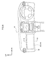
- Fig. 8 shows an exterior elevational view of an instrument panel in which a glove door incorporated-type knee airbag device relating to a present exemplary embodiment is mounted.
- Fig. 7 shows a schematic vertical section diagram illustrating a positional relationship between the glove door and a seated occupant, viewed from sideward in the vehicle.
- Fig. 6 shows an exploded perspective diagram of the glove door.
- Fig. 5 shows a magnified vertical sectional diagram of principal portions of the glove door incorporated-type knee airbag device relating to the present exemplary embodiment (a magnified sectional diagram taken along line 5-5 of Fig. 8 ).
- a glove box 14 for small items to be put into is provided at a position substantially opposing the knees of an occupant at a passenger seat side of an instrument panel 10, (more precisely, at an upper portion of an instrument panel lower 12 that constitutes a lower portion of the instrument panel 10).
- the glove box 14 is structured by a glove box main body 16 made of resin that is formed in a box shape and a glove door 20 that opens and closes an opening portion 18 of the glove box main body 16.
- the glove box main body 16 is disposed such that the opening portion 18 faces to the vehicle rearward side (a vehicle cabin inner side.).
- a glove door incorporated-type knee airbag device 40 is incorporated in the glove door 20 that closes the opening portion 18 of the glove box main body 16 mentioned above.
- the glove door 20 is provided with a glove door outer 24 in a rectangular panel shape that is disposed at the vehicle cabin inner side and forms a design surface, and a glove door inner 26 formed in a rectangular frame shape that is disposed at the vehicle forward side of the glove door outer 24 and is fitted to the glove door outer 24.
- the glove door outer 24 and the glove door inner 26 are both made of resin.
- the glove door outer 24 is structured as a two-layer structure, of a base member 28 that is formed in a substantially rectangular panel shape and a skin 30 that covers a vehicle cabin inner side surface of the base member 28.
- the base member 28 and the skin 30 are both made of resin, but the skin 30 is structured of a softer resin material than the base member 28.
- a pair of left and right stoppers 32 is provided standing from both sides of the lower edge side of the base member 28 of the glove door outer 24.
- the stoppers 32 protrude from a general portion 28A of the base member 28 in a direction orthogonal to the surface (to the vehicle forward side), and distal end portions thereof interfere with a wall surface of the glove box main body 16 when the glove door 20 is in a fully open state. Thus, the stoppers 32 serve to retain the glove door 20 at a fully open position.
- Hinges 34 that are formed in substantial letter L shapes in side view are provided at the inner sides of the stoppers 32. One end portions of the hinges 34 are fixed by screws or the like to the glove box main body 16, and the glove door 20 turns around an axis of turning Q in Fig. 5 when the glove door 20 is opening and closing.
- tear portions 36 are specified at a vehicle cabin outer side surface (the surface at the glove door inner 26 side) of the general portion 28A of the glove door outer 24.
- the tear portions 36 are in a substantial letter B shape that breaks when an inflation pressure of at least a predetermined value acts via an airbag door retainer 42 which is described below.
- the tear portions 36 are constituted by a width direction central tear portion 36A that extends along the vehicle width direction at a vehicle up-down direction central portion of the general portion 28A, a pair of left and right vertical direction tear portions 36B that extend in the vehicle up-down direction from each of the two end portions of the width direction central tear portion 36A, and lateral direction upper and lower tear portions 36C that link distal end portions of the vertical direction tear portions 36B to one another.
- the glove door inner 26 is structured to include a rectangular frame-form bottom wall portion 26A that opposes the general portion 28A of the base member 28 of the glove door outer 24, a pair of left and right side wall portions 26B that are formed integrally with two vehicle lateral direction side portions of the bottom wall portion 26A, and a pair of left and right protruding portions 26C that protrude towards vehicle width direction outer sides from end portions of the pair of left and right side wall portions 26B at the glove door outer 24 side thereof.
- Notches 38 are formed at lower edge sides of the protruding portions 26C, at positions opposing the stoppers 32 of the glove door outer 24. The stoppers 32 pass into these notches 38.
- the glove door outer 24 and the glove door inner 26 of the structure described above are joined together via vertical direction and horizontal direction ribs 39 that are formed at at least one of those two (see Fig. 5 ). Specifically, the glove door outer 24 and the glove door inner 26 are vibration-welded to distal end portions of the ribs 39.
- fastening with fasteners may be used or vibration welding and fastening may be used in combination, and a configuration in which the glove door outer 24 and the glove door inner 26 may be made integral is sufficient.
- the airbag door retainer 42 made of plastic formed in a substantially rectangular plate shape, is provided between the glove door outer 24 and glove door inner 26 described above.
- the airbag door retainer 42 is provided with a rectangular flat plate-form base portion 44 and a rectangular frame-form vertical wall portion 46, which is provided standing from vicinities of outer periphery portion of the base portion 44.
- Plural anchor holes 48 are formed with predetermined spacings in an upper portion and a lower portion of the vertical wall portion 46.
- the anchor holes 48 are structured as rectangular openings.
- a plural number of ribs for reinforcement 50 are provided standing between vicinity portions of the outer periphery portions of the base portion 44 and the vertical wall portion 46.
- the ribs for reinforcement 50 are disposed so as to span between those two, and are formed in right-angled triangle shapes in side view.
- Slits 52 are formed in a central portion (a region encircled by the vertical wall portion 46) of the base portion 44 of the airbag door retainer 42.
- the slits 52 are formed in a letter H shape in front view, by a pair of left and right vertical slits 52A and a lateral slit 52B that links the vertical slits 52A to one another.
- a pair of upper and lower airbag doors 54 is formed by these slits 52. Corner portions 54A at the lateral slit 52B side of each airbag door 54 are formed in circular arc shapes.
- Slacking portions 56 (see Fig. 5 ), which are formed in substantial letter V shapes in side view, are formed at turning axis sides of the airbag doors 54. When the airbag doors 54 are deploying, the slacking portions 56 are extended, such that the airbag doors 54 deploy smoothly.
- a pair of upper and lower ribs 60 that protrude toward the airbag door retainer 42 are integrally formed at an upper edge portion and a lower edge portion of a central opening portion 58 in the bottom wall portion 26A of the above-described glove door inner 26.
- these ribs 60 are provided to be substantially parallel with outer sides of an upper wall portion and a lower wall portion of the vertical wall portion 46 of the airbag door retainer 42.
- Respective distal end portions of the ribs 60 are welded (vibration-welded) to the base portion 44 of the airbag door retainer 42.
- the base portion 44 of the airbag door retainer 42 is fixed in a state that is nipped between the general portion 28A of the base member 28 of the glove door outer 24 and the ribs 60 of the glove door inner 26.
- an airbag module 62 is mounted at the central opening portion 58 of the glove door inner 26.
- the airbag module 62 is provided with a module case 64 made of metal.
- the module case 64 is formed in a box shape with a thin floor.
- An inflator fixing portion 66 which protrudes toward the vehicle rearward side, is provided at a central lower portion of a floor wall portion 64A of the module case 64 by an isosceles trapezoid shape being knocked in from the vehicle forward side.
- a shape of the inflator fixing portion 66 in a vertical sectional view forms a mountain shape.
- a pair of left and right bolt insertion holes 68 is formed in an inclined portion 66A at the vehicle upward side of this inflator fixing portion 66.
- a pair of stud bolts 72 (see Fig. 5 ), which protrude toward a radial direction outer side of an inflator 70 from an axial direction central portion of the inflator 70, are inserted into these bolt insertion holes 68, and nuts 74 are threadingly engaged therewith from a rear face side.
- the inflator 70 is fastened and fixed to the inclined portion 66A of the inflator fixing portion 66.
- Letter L-shaped attachment pieces 78 are attached to each of a total of four locations at two side portions of the module case 64.
- Bolt insertion holes 76 are formed at central portions of the attachment pieces 78.
- bolt insertion holes 80 are formed coaxially with the bolt insertion holes 76 at both sides of the central opening portion 58 of the glove door inner 26.
- the bolt insertion holes 76 of the attachment pieces 78 are made to correspond with the bolt insertion holes 80 at the glove door inner 26 side, and are fastened and fixed with unillustrated fastening members such as bolts or the like.
- the module case 64 is fixed to the central opening portion 58 of the glove door inner 26 from the vehicle forward side thereof.
- Long strip-form anchor fixtures 82 are attached to an upper portion and a lower portion of the module case 64.
- Anchor pieces 84 that are letter L-shaped in side view are integrally formed at one edge of the anchor fixtures 82 (at the airbag door retainer 42 side thereof).
- the anchor pieces 84 are plurally separately provided in correspondence with the aforementioned anchor holes 48 formed in the vertical wall portion 46 of the airbag door retainer 42.
- the airbag door retainer 42 is attached to the module case 64 by the anchor pieces 84 being inserted into and anchored at the anchor holes 48.
- the inflator 70 which serves as a gas generator, and a knee airbag 86 that is inflated by gas being emitted from the inflator 70 are assembled inside the module case 64.
- This inflator 70 is formed in a cylinder shape whose outer diameter is accommodated in the module case 64.
- a gas emission portion 88 is coaxially formed at an end portion of the axial direction of the inflator 70.
- the gas emission portion 88 has an outer diameter that is smaller than the outer diameter of the inflator 70, and plural gas emission holes are formed in a peripheral wall portion of the gas emission portion 88.
- the knee airbag 86 is accommodated in the module case 64 in a folded state. More specifically, it is folded to a size that can be accommodated in the module case 64 by an upper portion and a lower portion of the knee airbag 86 in a flat deployed state each being bellows-folded and brought toward a central portion. Then the inflator 70 is inserted into the central portion (a height direction central portion) of the knee airbag 86, and the stud bolts 72 protruding from the inflator 70 pass through the knee airbag 86 and are fixed to the inflator fixing portion 66 of the module case 64 by the procedure described above.
- the central opening portion 58 of the glove door inner 26 is closed off after assembly of the airbag module 62 by a rear face cover 92 made of resin, which is formed in a rectangular plate shape.
- Plural leg portions 94 are integrally formed from four edges of the rear face cover 92 towards the glove door inner 26. Pawls are formed at distal end portions of the leg portions 94.
- plural rectangular insertion holes 96 are formed in the bottom wall portion 26A of the glove door inner 26 at outer periphery portions of the central opening portion 58.
- the rear face cover 92 is attached to the vehicle forward side surface of the glove door inner 26 by the leg portions 94 being inserted into the insertion holes 96 and resiliently engaged.
- the knee airbag 86 is formed in a flat, substantially cuboid shape.
- An upper-lower pair of an upper tether 100 and a lower tether 102 is provided substantially in parallel inside the knee airbag 86.
- the upper tether 100 is formed in a long, narrow rectangular shape.
- the upper tether 100 is made integral with the knee airbag 86 by a front end portion 100A and a rear end portion 100B being stitched to a counter-occupant side base fabric portion 86A and an occupant side base fabric portion 86B of the knee airbag 86, respectively.
- a length direction dimension of the upper tether 100 is specified to be shorter than a width direction dimension of the knee airbag 86.
- the lower tether 102 is formed in a long, narrow rectangular shape.
- the lower tether 102 is made integral with the knee airbag 86 by a front end portion 102A and a rear end portion 102B being stitched to the counter-occupant side base fabric portion 86A and the occupant side base fabric portion 86B of the knee airbag 86, respectively.
- a length direction dimension of the lower tether 102 is specified to be shorter than the width direction dimension of the knee airbag 86.
- a thickness of the knee airbag 86 during deployment by inflation is regulated so as to be a predetermined thickness. Furthermore, because the upper tether 100 and the lower tether 102 are provided, the interior of the knee airbag 86 is divided into a middle flow path 108, an upper portion flow path 110, a lower portion flow path 112, and a pair of left and right side flow paths 114.
- the middle flow path 108 is demarcated by the upper tether 100 and the lower tether 102 and extends in the vehicle width direction.
- the upper portion flow path 110 is demarcated by the upper tether 100 and an outer periphery upper portion 86C of the knee airbag 86, and extends in the vehicle width direction.
- the lower portion flow path 112 is demarcated by the lower tether 102 and an outer periphery lower portion 86D of the knee airbag 86, and extends in the vehicle width direction.
- the left and right side flow paths 114 communicate in the vehicle up-down direction between respective length direction end portions of the middle flow path 108, the upper portion flow path 110 and the lower portion flow path 112.
- the aforementioned inflator 70 is disposed in a horizontal placement at a length direction middle portion of the middle flow path 108 of the knee airbag 86.
- the gas emission portion 88 of the inflator 70 is disposed so as to be located at the length direction middle portion of the middle flow path 108.
- the inflator 70 need not necessarily be disposed thus. If the gas emission portion 88 of the inflator 70 is disposed at a position that is offset from the length direction middle portion of the middle flow path 108, the flow may be straightened by an unillustrated diffuser (a flow-straightener) and gas may be emitted to the length direction middle portion of the middle flow path 108.
- an unillustrated diffuser a flow-straightener
- First opening portions 104 and second opening portions 106 are alternatingly formed in the aforementioned upper tether 100 and lower tether 102.
- the first opening portions 104 are large diameter gas through-flow holes that serve as gas through-flow opening portions.
- the second opening portions 106 are small diameter gas through-flow holes that serve as upper shin entry allowance portions. In other words, opening areas of the first opening portions 104 are specified to be larger than opening areas of the second opening portions 106.
- Both the first opening portions 104 and the second opening portions 106 correspond to a gas through-flow control portion of the present invention.
- two of the second opening portions 106 are formed in the upper tether 100.
- the second opening portions 106 are provided at positions that coincide with upper shin portions X of a seated occupant in a front view of the vehicle (see Fig. 4 ) when the seated occupant is a large occupant (the occupant shown by two-dot chain lines in Fig. 7 ).
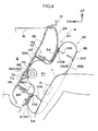
- Fig. 4 illustrates a state in which the glove door incorporated-type knee airbag device 40 is operating when the seated occupant is a large occupant, in a side view.
- the portion arrowed with the line X in Fig. 4 is the upper shin portions of the occupant.
- the upper shin portions are locations corresponding to directly below kneecaps (knee joints) Y.
- Fig. 1B is a diagram seen in plan view, the upper shin portions look to locate as being coincide with the kneecaps.
- the kneecaps Y are shown labeled from the center of the knees
- the upper shin portions X are shown labeled from outer peripheries of the shins.
- Fig. 2B and so forth are marked in a similar manner.
- two of the second opening portions 106 are formed in the lower tether 102.
- the second opening portions 106 are provided at positions that coincide with upper shin portions X of a seated occupant in the front view of the vehicle (see Fig. 4 ) when the seated occupant is a small occupant (the occupant shown by solid lines in Fig. 7 ).
- a pitch P1 of the second opening portions 106 of the upper tether 100 is specified to be larger than a pitch P2 of the second opening portions 106 of the lower tether 102 (see Fig. 1B ).
- first opening portions 104 are formed respectively at outer sides of and between the second opening portions 106.
- the first opening portions 104 and the second opening portions 106 are all formed as circular holes, and are arranged at matching positions in the vehicle width direction.
- a center line O of these first opening portions 104 and second opening portions 106 is disposed to be offset to the vehicle forward side by a distance ⁇ from a center line P of the thickness direction of the knee airbag 86 in the deployed state thereof.
- the knee airbag 86 in the folded state inflates and a bag inflation pressure acting on the tear portions 36 via the airbag door retainer 42 reaches a predetermined value, the tear portions 36 break, and the pair of airbag doors 54 are deployed upward and downward.
- the knee airbag 86 deploys by inflating in a space between the knees of the occupant and the glove door 20 (the instrument panel 10). As a result, the knees of the occupant are restrained by the knee airbag 86 and protected.
- the knee airbag 86 deploys rapidly in the vehicle width direction, and rapidly deploys even if a space between the knees of the occupant and the glove door 20 (the instrument panel 10) is narrow.
- the gas supplied through the middle flow path 108 in the vehicle width direction reaches to the left and right side flow paths 114, separates up and down, and is supplied into the upper portion flow path 110 and the lower portion flow path 112.
- the first opening portions 104 and the second opening portions 106 are formed in the upper tether 100 and the lower tether 102, a portion of the gas flowing through the middle flow path 108 in the vehicle width direction passes through the first opening portions 104 and the second opening portions 106 and flows into the upper portion flow path 110 and the lower portion flow path 112. Therefore, the knee airbag 86 is deployed by inflating rapidly both in the vehicle width direction and in the vehicle up-down direction. Flows of the gas are illustrated by arrows in Fig. 1A and Fig. 2A .
- the knee airbag 86 is disposed at the height of the knees of the occupants in the sitting state, if it is supposed that the occupant is sitting on the passenger seat in a state in which the knees are proximate to the glove door 20 or suchlike, the upper shin portions X are strongly pushed to the vehicle rearward side by deployment reaction force of the knee airbag 86 during deployment by inflation of the knee airbag 86.
- the second opening portions 106 with smaller diameters than the first opening portions 104 are disposed at positions that coincide with the upper shin portions X in the vehicle front view, a large amount of the gas is allowed to flow toward the first opening portions 104 which is apart from the second opening portions 106. Therefore, the upper shin portions X may enter further in toward the second opening portions 106, or the upper shin portions X that have entered further in are not strongly pressed to the vehicle rearward side. That is, because more of the gas flows through the first opening portions 104, a larger pressure force is generated at the first opening portions 104, and because less of the gas flows through the second opening portions 106, a smaller pressure force is generated at the second opening portions 106.
- loads on the upper shin portions X may be moderated.
- loads on the shins when the knee airbag 86 deploys by inflating in a state in which the knees of an occupant are proximate to the airbag door or suchlike may be moderated.
- the knee airbag 86 may be more quickly deployed by inflating in not only the vehicle width direction but also the vehicle up-down direction.
- the present exemplary embodiment includes the upper tether 100 and the lower tether 102, and the pitch P1 of the second opening portions 106 in the upper tether 100 is specified to be larger than the pitch P2 of the second opening portions 106 in the lower tether 102, the upper tether 100 may be used for occupants with large physiques and the lower tether 102 used for occupants with small physiques. Therefore, according to the present exemplary embodiment, the knee airbag 86 may be deployed by inflating rapidly in both the vehicle width direction and the vehicle up-down direction, and a load moderation effect on the upper shin portions X and knee restraint performance may be obtained in accordance with the physiques of occupants.
- the first opening portions 104 and the second opening portions 106 are disposed to be offset by the distance ⁇ to the vehicle forward side from the center line P of the thickness direction of the knee airbag 86, even when the upper shin portions X of the occupant enter in towards the second opening portions 106, the second opening portions 106 are unlikely to be closed up. Therefore, inflation deployment performance of the knee airbag 86 in the vehicle up-down direction is excellently assured. As a result, consistent inflation deployment performance of the knee airbag 86 in the vehicle up-down direction may be assured.
- the airbag module 62 may be made compact accommodation, and a gas supply path from the inflator 70 to the knee airbag 86 may be made short.
- the device as a whole may be made compact and a more rapid supply of gas from the inflator 70 to the knee airbag 86 may be enabled.
- the glove door incorporated-type knee airbag device 40 is installed in the glove door 20 (the instrument panel 10) provided at the vehicle forward side of the passenger seat, lower leg protection performance of an occupant sitting on the passenger seat may be improved.
- the airbag module 62 is incorporated in the glove door 20, there is no need to reserve a dedicated space for stowing the knee airbag 86 in the folded state inside the instrument panel 10. Therefore, a degree of freedom of design of the instrument panel 10 as in related art may be preserved.
- both the first opening portions 104 and the second opening portions 106 are formed in the lower tether 102, but only the first opening portions 104 are formed in the upper tether 100.
- the upper shin portions X are allowed to enter in only for a small occupant. That is, when the knee airbag 120 deploys by inflating, to what extent the upper shin portions X of the occupant are pushed to the vehicle rearward side varies with relative positional relationships of the deployment height of the knee airbag 120 (in other words, an installation position of the airbag module 62) and the height of the knees of the occupant (which may instead be referred to as the height of the upper shin portions X).
- a load on the shins when the knee airbag 120 deploys by inflating may be small for a large occupant and a load on the shins may be large for a small occupant, depending on a style of curvature and the like of the instrument panel 10 and the glove door 20 or the like.
- the second opening portions 106 it is sufficient just for the second opening portions 106 to be provided only in the lower tether 102.
- the second opening portions 106 may be provided only at the upper tether 100.
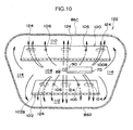
- a knee airbag 122 illustrated in Fig. 10 is characterized by the shapes of first opening portions 124 in the upper tether 100 and the lower tether 102 being not circles but oval shapes.
- the shapes of the first opening portions 124 are oval shapes, but they may be elliptical shapes, rectangles or the like, and it is sufficient that the shapes have a longer length in the vehicle width direction than a length in the vehicle front-rear direction.
- the first opening portions 124 in the middle are oval shapes, but it may be that only the first opening portions 124 at one length direction end portion are oval shapes, and it may be that only the first opening portions 124 at both length direction end portions are oval shapes.
- both the first opening portions 104 and the second opening portions 106 are formed in the lower tether 102, but neither the first opening portions 104 nor the second opening portions 106 are formed in an upper tether 130.
- this is a configuration in which both length direction end portions of the upper tether 130 are inflected in the vehicle upward direction, and taper portions 132 are applied to the both length direction end portions of the upper tether 130.
- the taper portions 132 need not necessarily have linear forms and they may have curved shapes.
- the gas emitted from the gas emission portion 88 of the inflator 70 is supplied in the vehicle width direction through a middle flow path 134.
- the taper portions 132 are provided at the two length direction end portions of the upper tether 130, the gas is quickly supplied to the vehicle upward side. Therefore, this is favorable if it is desired that the two end portions of the knee airbag 128 be deployed by inflating as quickly as possible to the vehicle upward side while the whole of the knee airbag 128 is rapidly deployed in the vehicle width direction.
- non-inflation portions 142 instead of the second opening portions 106 are specified at formation positions of the openings in the upper tether 100 and the lower tether 102. That is, this is a configuration in which the non-inflation portions 142 are specified without opening portions being provided at all at positions coinciding with the knees of an occupant in the vehicle front view.
- the first opening portions 104 are similarly specified.
- the non-inflation portions 142 are specified at portions of the upper tether 100 and the lower tether 102 at which the upper shin portions X of an occupant enter in, the gas does not pass in the vehicle up-down direction through these portions. Therefore, the regions of formation of the non-inflation portions 142 in the knee airbag 86 may be suppressed or prevented from strongly pressing the upper shin portions X of the occupant in the vehicle rearward direction.
- the glove door incorporated-type knee airbag device 40 is described as operating during a frontal collision, but this is not to be limiting.
- a collision predictor such as a pre-crash sensor or the like may be installed in the vehicle and a glove door incorporated-type knee airbag device may be operated when a collision is predicted by the collision predictor.
- the inflator and airbag as described above may be connected by a connector such as a hose or the like, and the inflator may be provided at the glove box main body 16, or provided at the instrument panel 10, or provided at the body in an inner panel reinforcement or the like, or provided at equipped machinery such as an air-conditioning unit or the like.
- all of the first opening portions 104 and the second opening portions 106 are disposed to be offset to the vehicle forward side by the distance ⁇ from the center line P of the thickness direction of the knee airbag 86, but it is sufficient that at least the second opening portions 106 be offset. Therefore, for example, a configuration in which only the central first opening portions 104 and the two second opening portions 106 at both sides thereof are offset to the vehicle forward side from the center line P while the first opening portions 104 at both sides are disposed on the center line P of the thickness direction of the knee airbag 86 is also to be included in the present invention recited in any of the fifth to seventh aspects.
Abstract
Description
- The present invention relates to a knee airbag device for a vehicle, which is for protecting the knees of an occupant.
- In recent years, with a view to improving occupant protection performance at times of collisions, the installation in vehicles of vehicle knee airbag devices, which deploy by inflating a knee airbag at the time of a collision and restrain the kneecaps of occupants (hereinafter referred to simply as "the knees"), has been promoted. Within patent references of Japanese Patent Application Laid-Open (JP-A) No.
11-321539 JP-A No. 2002-337642 JP-A No. 2002-356137 JP-A No. 2003-175793 JP-A No. 2005-096576 JP-A No. 11-321539 - However, in a case with the above-described technology, the middle chamber deploys by inflating at the height of a vicinity of upper portions (just below the kneecaps) of the shins of an occupant (hereinafter referred to simply as "the upper shin portions"). Therefore, if the occupant is sitting on a vehicle seat in a state in which the knees are close to the airbag door or a state of touching the same (hereinafter, the two states are collectively referred to as a proximate or suchlike state), the upper shin portions are pushed toward the rearward side of the vehicle by the middle chamber and a load is applied to the shins.
- In consideration of the circumstances described above, an object of the present invention is to provide a knee airbag device for a vehicle that is capable of moderating a load on the shins when a knee airbag deploys by inflating in a state in which the knees of an occupant are in a state proximate to an airbag door or suchlike.
- A knee airbag device for a vehicle relating to a first aspect of the present invention includes: a gas generator that, by operating, generates gas; a knee airbag that is accommodated in a folded state and is disposed at a height of knees of an occupant in a sitting state, and that deploys by inflating toward the knees of the occupant with gas supplied from the gas generator; an upper tether and a lower tether that span between an occupant side base fabric portion and a counter-occupant side base fabric portion of an interior of the knee airbag, and that are disposed along a vehicle width direction at up-down positions sandwiching a gas inflow portion at which the gas from the gas generator inflows; and a gas through-flow control portion that is provided at at least one of the upper tether and the lower tether. The gas through-flow control portion is structured to include gas through-flow opening portions that are provided at positions offset in the vehicle width direction relative to upper shin portions of the occupant in a vehicle front view, and upper shin entry allowance portions that are provided at positions coinciding with the upper shin portions in the vehicle front view and that are constituted as opening portions smaller than the gas through-flow opening portions or non-opening portions that are not open.
- A second aspect of the present invention is the knee airbag device for a vehicle recited for the first aspect, in which the upper shin entry allowance portions are small opening portions whose opening areas are specified to be smaller than the gas through-flow opening portions.
- A third aspect of the present invention is the knee airbag device for a vehicle recited for the first aspect, and a fourth aspect of the present invention is the knee airbag device for a vehicle recited for the second aspect, in each of which the gas through-flow control portion is provided at both of the upper tether and the lower tether, and specified with a pitch of the adjacent upper shin entry allowance portions at the upper tether being larger than a pitch of the adjacent upper shin entry allowance portions at the lower tether.
- A fifth aspect of the present invention is the knee airbag device for a vehicle recited for the first aspect, a sixth aspect of the present invention is the knee airbag device for a vehicle recited for the second aspect, and a seventh aspect of the present invention is the knee airbag device for a vehicle recited for the second aspect, in each of which the upper shin entry allowance portions are constituted as opening portions smaller than the gas through-flow opening portions, and at least the upper shin entry allowance portions of the gas through-flow control portion are disposed to be offset to the vehicle forward side relative to a center line of a thickness direction of the knee airbag.
- A fourteenth aspect of the present invention is the knee airbag device for a vehicle recited for the first aspect, in which the gas generator is disposed at the counter-occupant side base fabric portion side of the interior of the knee airbag, between the upper tether and the lower tether.
- A fifteenth aspect of the present invention is the knee airbag device for a vehicle recited for the first aspect, in which a device main body is installed at a vehicle interior member provided at the vehicle forward side of a passenger seat.
- A sixteenth aspect of the present invention is the knee airbag device for a vehicle recited for the fifteenth aspect, in which the vehicle interior member is a glove door provided at an instrument panel.
- According to the first aspect of the present invention, when the gas generator operates, gas is generated. The generated gas flows into the knee airbag that has been stowed in the folded state.
- More specifically, in the present aspect, the upper tether and the lower tether are arranged along the vehicle width direction at upper and lower positions sandwiching the gas inflow portion inside the knee airbag. The upper tether and the lower tether span between the occupant side base fabric portion of the knee airbag and the counter-occupant side base fabric portion. Thus, a thickness of the knee airbag during inflation is regulated. Moreover, gas inflowing through the gas inflow portion first passes along a flow path between the upper tether and the lower tether and is supplied in the vehicle width direction. Therefore, the knee airbag is rapidly deployed by inflating in the vehicle width direction (to left and right) for restraining the knees of the occupant.
- Further, a through-flow control portion that is configured to include the gas through-flow opening portions and the upper shin entry allowance portions is provided at at least one of the above-mentioned upper tether and lower tether. The upper shin entry allowance portions are structured as opening portions smaller than the gas through-flow opening portions or as non-opening portions that are not open. Thus, a portion of the gas flowing in the vehicle width direction between the upper tether and the lower tether passes through the gas through-flow opening portions and flows to the vehicle upward side or the vehicle downward side, or in the vehicle up-down direction. Therefore, as well as rapidly deploying by inflation in the vehicle width direction, the knee airbag rapidly deploys by inflation to the vehicle upward side or the vehicle downward side, or in the vehicle up-down direction.
- Now, in the present aspect, because the knee airbag is disposed at the height of the knees of the occupant in a sitting state, if it is supposed that the occupant is sitting on the vehicle seat in a state in which the knees are proximate to the knee airbag or suchlike (with a vehicle interior member interposed therebetween), the upper shin portions are strongly pushed to the vehicle rearward side by a deployment force of the knee airbag during the deployment by inflation of the knee airbag. However, with the present aspect, because the upper shin entry allowance portions that are constituted as opening portions smaller than the gas through-flow opening portions or as non-opening portions that are not open are disposed at the positions that coincide with the upper shin portions in the vehicle front view, a large amount of the gas flows toward the gas through-flow opening portions which are apart from the upper shin entry allowance portions. Therefore, the upper shin portions may enter further into the upper shin entry allowance portions, or the upper shin portions that have entered further are not strongly pressed to the vehicle rearward side. Therefore, a load on the upper shin portions may be moderated.
- According to the second aspect of the present invention, because the upper shin entry allowance portions are small opening portions whose opening areas are specified to be smaller than the gas through-flow opening portions, deployment by inflation of the knee airbag to the vehicle upward side or vehicle downward side or in the vehicle up-down direction is quicker than in a case in which the upper shin entry allowance portions are constituted as the non-opening portions.
- According to the third aspect and fourth aspect of the present invention, because the gas through-flow control portion is provided at both the upper tether and the lower tether, the gas generated from the gas generator is both supplied in the vehicle width direction along the flow path between the upper tether and the lower tether and flows from the flow path in the vehicle up-down direction.
- Here, in the present aspect, because the pitch of the adjacent upper shin entry allowance portions at the upper tether is specified to be larger than the pitch of the adjacent upper shin entry allowance portions at the lower tether, the upper tether with the larger pitch may be used for an occupant with a large physique, and the lower tether with the smaller pitch may be used for an occupant with a small physique.
- According to the fifth to seventh aspects of the present invention, because at least the upper shin entry allowance portions of the gas through-flow control portion are disposed to be offset to the vehicle forward side relative to a thickness direction center line of the knee airbag, even if the upper shin portions of the occupant enter towards the upper shin entry allowance portions, the opening portions that structure the upper shin entry allowance portions are unlikely to be closed off. Therefore, deployment performance of the knee airbag in the vehicle up-down direction is excellently assured.
- According to the fourteenth aspect of the present invention, because the gas generator is disposed at the counter-occupant side base fabric portion side of the interior of the knee airbag and between the upper tether and the lower tether, more compact accommodation is possible and a gas supply path from the gas generator to the knee airbag may be made shorter.
- According to the fifteenth aspect of the present invention, because the device main body is installed at the vehicle interior member provided at the vehicle forward side of the passenger seat, the knees of an occupant sitting on the passenger seat are restrained.
- According to the sixteenth aspect of the present invention, because the vehicle interior member is a glove door provided at the instrument panel, the knee airbag is deployed by inflating from the glove door. Therefore, there is no need to reserve a dedicated space inside the instrument panel for stowing the knee airbag in the folded state.
- As described above, the knee airbag device for a vehicle relating to the first aspect of the present invention has an excellent effect in that, in a state in which the knees of an occupant are proximate to the airbag door or suchlike, a load on the shins when the knee airbag deploys by inflation is moderated.
- The knee airbag device for a vehicle relating to the second aspect of the present invention has an excellent effect in that the airbag may be more quickly deployed by inflation to the vehicle upward side or the vehicle downward side, or to the vehicle up-down direction.
- The knee airbag devices for a vehicle relating to the third aspect and the fourth aspect of the present invention have excellent effects in that the airbag may be rapidly deployed by inflation in both the vehicle width direction and the vehicle up-down direction, and in that the load moderation effect on the shins and the knee restraint performance may be provided in accordance with physiques of occupants.
- The knee airbag devices for a vehicle relating to the fifth to seventh aspects of the present invention have an excellent effect in that consistent inflation deployment performance may be assured.
- The knee airbag device for a vehicle relating to the fourteenth aspect of the present invention has excellent effects in that the whole device may be made compact and in that a more rapid supply of gas from the gas generator to the knee airbag may be achieved.
- The knee airbag device for a vehicle relating to the fifteenth aspect of the present invention has an excellent effect in that lower leg protection performance for an occupant sitting on a passenger seat may be improved.
- The knee airbag device for a vehicle relating to the sixteenth aspect of the present invention has an excellent effect in that a flexibility of design of the vehicle interior member may be maintained as in related art.
-
-
Fig. 1A is a vertical sectional diagram illustrating a state in which a knee airbag of a glove door incorporated-type knee airbag device relating to a present exemplary embodiment deploys by inflating, in relation to a small occupant. -
Fig. 1B is a plan diagram illustrating the state in which the knee airbag of the glove door incorporated-type knee airbag device relating to the present exemplary embodiment deploys by inflating, in relation to the small occupant. -
Fig. 2A is a vertical sectional diagram illustrating the state in which the knee airbag of the glove door incorporated-type knee airbag device relating to the present exemplary embodiment deploys by inflating, in relation to a large occupant. -
Fig. 2B is a plan diagram illustrating the state in which the knee airbag of the glove door incorporated-type knee airbag device relating to the present exemplary embodiment deploys by inflating, in relation to the large occupant. -
Fig. 3 is a perspective diagram illustrating an inflation deployment state of the knee airbag illustrated inFig. 1 . -
Fig. 4 is a vertical sectional diagram illustrating an operating state of the glove door incorporated-type knee airbag device relating to the present exemplary embodiment, viewed from sideward in the vehicle. -
Fig. 5 is a magnified vertical sectional diagram of principal portions of the glove door incorporated-type knee airbag device (a magnified sectional diagram taken along a line 5-5 ofFig. 8 ). -
Fig. 6 is an exploded perspective diagram of the glove door. -
Fig. 7 is a schematic vertical section diagram illustrating a positional relationship between the glove door and a seated occupant, viewed from sideward in the vehicle. -
Fig. 8 is an exterior elevational view of an instrument panel in which the glove door incorporated-type knee airbag device relating to the present exemplary embodiment is installed. -
Fig. 9 is a vertical sectional diagram illustrating a knee airbag relating to a first variation. -
Fig. 10 is a vertical sectional diagram illustrating a knee airbag relating to a second variation. -
Fig. 11 is a vertical sectional diagram illustrating a knee airbag relating to a third variation. -
Fig. 12 is a vertical sectional diagram illustrating a knee airbag relating to a fourth variation. - Herebelow, several exemplary embodiments of the knee airbag device for a vehicle relating to the present invention are described using
Fig. 1A to Fig. 12 . An arrow FR that is shown as appropriate in these drawings represents a vehicle forward side, an arrow UP represents a vehicle upward side, and an arrow IN represents a vehicle width direction inner side. -
Fig. 8 shows an exterior elevational view of an instrument panel in which a glove door incorporated-type knee airbag device relating to a present exemplary embodiment is mounted.Fig. 7 shows a schematic vertical section diagram illustrating a positional relationship between the glove door and a seated occupant, viewed from sideward in the vehicle.Fig. 6 shows an exploded perspective diagram of the glove door.Fig. 5 shows a magnified vertical sectional diagram of principal portions of the glove door incorporated-type knee airbag device relating to the present exemplary embodiment (a magnified sectional diagram taken along line 5-5 ofFig. 8 ). Firstly, structure of the device as a whole is described using these drawings. - As illustrated in
Fig. 8 , to serve as a vehicle interior member, aglove box 14 for small items to be put into is provided at a position substantially opposing the knees of an occupant at a passenger seat side of aninstrument panel 10, (more precisely, at an upper portion of an instrument panel lower 12 that constitutes a lower portion of the instrument panel 10). As illustrated inFig. 7 , theglove box 14 is structured by a glove boxmain body 16 made of resin that is formed in a box shape and aglove door 20 that opens and closes anopening portion 18 of the glove boxmain body 16. The glove boxmain body 16 is disposed such that the openingportion 18 faces to the vehicle rearward side (a vehicle cabin inner side.). - As illustrated in
Fig. 5 to Fig. 7 , a glove door incorporated-typeknee airbag device 40 is incorporated in theglove door 20 that closes the openingportion 18 of the glove boxmain body 16 mentioned above. Theglove door 20 is provided with a glove door outer 24 in a rectangular panel shape that is disposed at the vehicle cabin inner side and forms a design surface, and a glove door inner 26 formed in a rectangular frame shape that is disposed at the vehicle forward side of the glove door outer 24 and is fitted to the glove door outer 24. The glove door outer 24 and the glove door inner 26 are both made of resin. - As illustrated in
Fig. 5 andFig. 6 , the glove door outer 24 is structured as a two-layer structure, of abase member 28 that is formed in a substantially rectangular panel shape and askin 30 that covers a vehicle cabin inner side surface of thebase member 28. Thebase member 28 and theskin 30 are both made of resin, but theskin 30 is structured of a softer resin material than thebase member 28. A pair of left andright stoppers 32 is provided standing from both sides of the lower edge side of thebase member 28 of the glove door outer 24. Thestoppers 32 protrude from ageneral portion 28A of thebase member 28 in a direction orthogonal to the surface (to the vehicle forward side), and distal end portions thereof interfere with a wall surface of the glove boxmain body 16 when theglove door 20 is in a fully open state. Thus, thestoppers 32 serve to retain theglove door 20 at a fully open position. -
Hinges 34 that are formed in substantial letter L shapes in side view are provided at the inner sides of thestoppers 32. One end portions of thehinges 34 are fixed by screws or the like to the glove boxmain body 16, and theglove door 20 turns around an axis of turning Q inFig. 5 when theglove door 20 is opening and closing. - As illustrated in
Fig. 5 , tearportions 36 are specified at a vehicle cabin outer side surface (the surface at the glove door inner 26 side) of thegeneral portion 28A of the glove door outer 24. Thetear portions 36 are in a substantial letter B shape that breaks when an inflation pressure of at least a predetermined value acts via anairbag door retainer 42 which is described below. Thetear portions 36 are constituted by a width directioncentral tear portion 36A that extends along the vehicle width direction at a vehicle up-down direction central portion of thegeneral portion 28A, a pair of left and right verticaldirection tear portions 36B that extend in the vehicle up-down direction from each of the two end portions of the width directioncentral tear portion 36A, and lateral direction upper andlower tear portions 36C that link distal end portions of the verticaldirection tear portions 36B to one another. - Meanwhile, the glove door inner 26 is structured to include a rectangular frame-form
bottom wall portion 26A that opposes thegeneral portion 28A of thebase member 28 of the glove door outer 24, a pair of left and right side wall portions 26B that are formed integrally with two vehicle lateral direction side portions of thebottom wall portion 26A, and a pair of left and right protrudingportions 26C that protrude towards vehicle width direction outer sides from end portions of the pair of left and right side wall portions 26B at the glove door outer 24 side thereof.Notches 38 are formed at lower edge sides of the protrudingportions 26C, at positions opposing thestoppers 32 of the glove door outer 24. Thestoppers 32 pass into thesenotches 38. - The glove door outer 24 and the glove door inner 26 of the structure described above are joined together via vertical direction and
horizontal direction ribs 39 that are formed at at least one of those two (seeFig. 5 ). Specifically, the glove door outer 24 and the glove door inner 26 are vibration-welded to distal end portions of theribs 39. However, fastening with fasteners may be used or vibration welding and fastening may be used in combination, and a configuration in which the glove door outer 24 and the glove door inner 26 may be made integral is sufficient. - As illustrated in
Fig. 5 andFig. 6 , theairbag door retainer 42, made of plastic formed in a substantially rectangular plate shape, is provided between the glove door outer 24 and glove door inner 26 described above. Theairbag door retainer 42 is provided with a rectangular flat plate-form base portion 44 and a rectangular frame-formvertical wall portion 46, which is provided standing from vicinities of outer periphery portion of thebase portion 44. Plural anchor holes 48 are formed with predetermined spacings in an upper portion and a lower portion of thevertical wall portion 46. The anchor holes 48 are structured as rectangular openings. A plural number of ribs forreinforcement 50 are provided standing between vicinity portions of the outer periphery portions of thebase portion 44 and thevertical wall portion 46. The ribs forreinforcement 50 are disposed so as to span between those two, and are formed in right-angled triangle shapes in side view. -
Slits 52 are formed in a central portion (a region encircled by the vertical wall portion 46) of thebase portion 44 of theairbag door retainer 42. Theslits 52 are formed in a letter H shape in front view, by a pair of left and rightvertical slits 52A and alateral slit 52B that links thevertical slits 52A to one another. A pair of upper andlower airbag doors 54 is formed by theseslits 52.Corner portions 54A at the lateral slit 52B side of eachairbag door 54 are formed in circular arc shapes. Slacking portions 56 (seeFig. 5 ), which are formed in substantial letter V shapes in side view, are formed at turning axis sides of theairbag doors 54. When theairbag doors 54 are deploying, the slackingportions 56 are extended, such that theairbag doors 54 deploy smoothly. - As illustrated in
Fig. 5 , a pair of upper andlower ribs 60 that protrude toward theairbag door retainer 42 are integrally formed at an upper edge portion and a lower edge portion of acentral opening portion 58 in thebottom wall portion 26A of the above-described glove door inner 26. In the assembled state of theglove door 20, theseribs 60 are provided to be substantially parallel with outer sides of an upper wall portion and a lower wall portion of thevertical wall portion 46 of theairbag door retainer 42. Respective distal end portions of theribs 60 are welded (vibration-welded) to thebase portion 44 of theairbag door retainer 42. Thus, thebase portion 44 of theairbag door retainer 42 is fixed in a state that is nipped between thegeneral portion 28A of thebase member 28 of the glove door outer 24 and theribs 60 of the glove door inner 26. - As illustrated in
Fig. 5 andFig. 6 , anairbag module 62 is mounted at thecentral opening portion 58 of the glove door inner 26. Theairbag module 62 is provided with amodule case 64 made of metal. Themodule case 64 is formed in a box shape with a thin floor. Aninflator fixing portion 66, which protrudes toward the vehicle rearward side, is provided at a central lower portion of afloor wall portion 64A of themodule case 64 by an isosceles trapezoid shape being knocked in from the vehicle forward side. A shape of theinflator fixing portion 66 in a vertical sectional view forms a mountain shape. A pair of left and right bolt insertion holes 68 is formed in aninclined portion 66A at the vehicle upward side of thisinflator fixing portion 66. A pair of stud bolts 72 (seeFig. 5 ), which protrude toward a radial direction outer side of an inflator 70 from an axial direction central portion of the inflator 70, are inserted into these bolt insertion holes 68, andnuts 74 are threadingly engaged therewith from a rear face side. Thus, theinflator 70 is fastened and fixed to theinclined portion 66A of theinflator fixing portion 66. - Letter L-shaped
attachment pieces 78 are attached to each of a total of four locations at two side portions of themodule case 64. Bolt insertion holes 76 are formed at central portions of theattachment pieces 78. In correspondence therewith, bolt insertion holes 80 are formed coaxially with the bolt insertion holes 76 at both sides of thecentral opening portion 58 of the glove door inner 26. The bolt insertion holes 76 of theattachment pieces 78 are made to correspond with the bolt insertion holes 80 at the glove door inner 26 side, and are fastened and fixed with unillustrated fastening members such as bolts or the like. Thus, themodule case 64 is fixed to thecentral opening portion 58 of the glove door inner 26 from the vehicle forward side thereof. - Long strip-
form anchor fixtures 82 are attached to an upper portion and a lower portion of themodule case 64.Anchor pieces 84 that are letter L-shaped in side view are integrally formed at one edge of the anchor fixtures 82 (at theairbag door retainer 42 side thereof). Theanchor pieces 84 are plurally separately provided in correspondence with the aforementioned anchor holes 48 formed in thevertical wall portion 46 of theairbag door retainer 42. Theairbag door retainer 42 is attached to themodule case 64 by theanchor pieces 84 being inserted into and anchored at the anchor holes 48. - As illustrated in
Fig. 5 , theinflator 70, which serves as a gas generator, and aknee airbag 86 that is inflated by gas being emitted from the inflator 70 are assembled inside themodule case 64. This inflator 70 is formed in a cylinder shape whose outer diameter is accommodated in themodule case 64. Agas emission portion 88 is coaxially formed at an end portion of the axial direction of theinflator 70. Thegas emission portion 88 has an outer diameter that is smaller than the outer diameter of the inflator 70, and plural gas emission holes are formed in a peripheral wall portion of thegas emission portion 88. - Meanwhile, the
knee airbag 86 is accommodated in themodule case 64 in a folded state. More specifically, it is folded to a size that can be accommodated in themodule case 64 by an upper portion and a lower portion of theknee airbag 86 in a flat deployed state each being bellows-folded and brought toward a central portion. Then the inflator 70 is inserted into the central portion (a height direction central portion) of theknee airbag 86, and thestud bolts 72 protruding from the inflator 70 pass through theknee airbag 86 and are fixed to theinflator fixing portion 66 of themodule case 64 by the procedure described above. Thus, theknee airbag 86 is assembled in a state of being nipped between the inflator 70 and theinflator fixing portion 66. In the state in which the glove door incorporated-typeknee airbag device 40 is assembled to the vehicle, theinflator 70 of theknee airbag 86 serves as an inflow portion 87 (seeFig. 4 ). - The
central opening portion 58 of the glove door inner 26 is closed off after assembly of theairbag module 62 by arear face cover 92 made of resin, which is formed in a rectangular plate shape.Plural leg portions 94 are integrally formed from four edges of therear face cover 92 towards the glove door inner 26. Pawls are formed at distal end portions of theleg portions 94. Correspondingly, plural rectangular insertion holes 96 are formed in thebottom wall portion 26A of the glove door inner 26 at outer periphery portions of thecentral opening portion 58. Therear face cover 92 is attached to the vehicle forward side surface of the glove door inner 26 by theleg portions 94 being inserted into the insertion holes 96 and resiliently engaged. - Next, principal elements of the present exemplary embodiment are described.
- As illustrated in
Fig. 1A to Fig. 4 , theknee airbag 86 is formed in a flat, substantially cuboid shape. An upper-lower pair of anupper tether 100 and alower tether 102 is provided substantially in parallel inside theknee airbag 86. Theupper tether 100 is formed in a long, narrow rectangular shape. Theupper tether 100 is made integral with theknee airbag 86 by afront end portion 100A and arear end portion 100B being stitched to a counter-occupant sidebase fabric portion 86A and an occupant sidebase fabric portion 86B of theknee airbag 86, respectively. A length direction dimension of theupper tether 100 is specified to be shorter than a width direction dimension of theknee airbag 86. - Similarly, the
lower tether 102 is formed in a long, narrow rectangular shape. Thelower tether 102 is made integral with theknee airbag 86 by afront end portion 102A and arear end portion 102B being stitched to the counter-occupant sidebase fabric portion 86A and the occupant sidebase fabric portion 86B of theknee airbag 86, respectively. A length direction dimension of thelower tether 102 is specified to be shorter than the width direction dimension of theknee airbag 86. - Because the
upper tether 100 and thelower tether 102 are provided, a thickness of theknee airbag 86 during deployment by inflation is regulated so as to be a predetermined thickness. Furthermore, because theupper tether 100 and thelower tether 102 are provided, the interior of theknee airbag 86 is divided into amiddle flow path 108, an upperportion flow path 110, a lowerportion flow path 112, and a pair of left and rightside flow paths 114. Themiddle flow path 108 is demarcated by theupper tether 100 and thelower tether 102 and extends in the vehicle width direction. The upperportion flow path 110 is demarcated by theupper tether 100 and an outer peripheryupper portion 86C of theknee airbag 86, and extends in the vehicle width direction. The lowerportion flow path 112 is demarcated by thelower tether 102 and an outer peripherylower portion 86D of theknee airbag 86, and extends in the vehicle width direction. The left and rightside flow paths 114 communicate in the vehicle up-down direction between respective length direction end portions of themiddle flow path 108, the upperportion flow path 110 and the lowerportion flow path 112. - The
aforementioned inflator 70 is disposed in a horizontal placement at a length direction middle portion of themiddle flow path 108 of theknee airbag 86. When the inflator 70 is disposed thus, thegas emission portion 88 of the inflator 70 is disposed so as to be located at the length direction middle portion of themiddle flow path 108. However, the inflator 70 need not necessarily be disposed thus. If thegas emission portion 88 of the inflator 70 is disposed at a position that is offset from the length direction middle portion of themiddle flow path 108, the flow may be straightened by an unillustrated diffuser (a flow-straightener) and gas may be emitted to the length direction middle portion of themiddle flow path 108. - First opening
portions 104 and second openingportions 106 are alternatingly formed in the aforementionedupper tether 100 andlower tether 102. Thefirst opening portions 104 are large diameter gas through-flow holes that serve as gas through-flow opening portions. Thesecond opening portions 106 are small diameter gas through-flow holes that serve as upper shin entry allowance portions. In other words, opening areas of the first openingportions 104 are specified to be larger than opening areas of thesecond opening portions 106. Both the first openingportions 104 and thesecond opening portions 106 correspond to a gas through-flow control portion of the present invention. - As illustrated in
Fig. 1A to Fig. 2B , two of thesecond opening portions 106 are formed in theupper tether 100. As illustrated inFig. 2B , thesecond opening portions 106 are provided at positions that coincide with upper shin portions X of a seated occupant in a front view of the vehicle (seeFig. 4 ) when the seated occupant is a large occupant (the occupant shown by two-dot chain lines inFig. 7 ). - In addition,
Fig. 4 illustrates a state in which the glove door incorporated-typeknee airbag device 40 is operating when the seated occupant is a large occupant, in a side view. The portion arrowed with the line X inFig. 4 is the upper shin portions of the occupant. The upper shin portions are locations corresponding to directly below kneecaps (knee joints) Y. BecauseFig. 1B is a diagram seen in plan view, the upper shin portions look to locate as being coincide with the kneecaps. However, in order to distinguish the two, the kneecaps Y are shown labeled from the center of the knees, and the upper shin portions X are shown labeled from outer peripheries of the shins.Fig. 2B and so forth are marked in a similar manner. - Similarly, as illustrated in
Fig. 1A to Fig. 2B , two of thesecond opening portions 106 are formed in thelower tether 102. As illustrated inFig. 1B , thesecond opening portions 106 are provided at positions that coincide with upper shin portions X of a seated occupant in the front view of the vehicle (seeFig. 4 ) when the seated occupant is a small occupant (the occupant shown by solid lines inFig. 7 ). - Accordingly, a pitch P1 of the
second opening portions 106 of the upper tether 100 (seeFig. 2B ) is specified to be larger than a pitch P2 of thesecond opening portions 106 of the lower tether 102 (seeFig. 1B ). - Herein, the first opening
portions 104 are formed respectively at outer sides of and between thesecond opening portions 106. - As illustrated in
Fig. 1B andFig. 2B , the first openingportions 104 and thesecond opening portions 106 are all formed as circular holes, and are arranged at matching positions in the vehicle width direction. A center line O of these first openingportions 104 and second openingportions 106 is disposed to be offset to the vehicle forward side by a distance δ from a center line P of the thickness direction of theknee airbag 86 in the deployed state thereof. - - Operation and Effects of the Present Exemplary Embodiment -
- Next, operation and effects of the present exemplary embodiment are described
- When a vehicle in which the glove door incorporated-type
knee airbag device 40 with the structure described above is employed has a frontal collision, this state is detected by an unillustrated collision detector, and a detection signal is outputted to an airbag electronic control unit (ECU). When airbag operation is decided on by the airbag ECU, various airbag devices operate at the driver seat side. In addition, the glove door incorporated-typeknee airbag device 40 at the passenger seat side operates. That is, a predetermined current is passed through a squib in theinflator 70 of theairbag module 62 incorporated in theglove door 20, and the inflator 70 is operated. Hence, gas is generated from the inflator 70, and this gas is supplied into theknee airbag 86 accommodated in theglove door 20 in the folded state and causes the same to inflate. - When the
knee airbag 86 in the folded state inflates and a bag inflation pressure acting on thetear portions 36 via theairbag door retainer 42 reaches a predetermined value, thetear portions 36 break, and the pair ofairbag doors 54 are deployed upward and downward. Hence, theknee airbag 86 deploys by inflating in a space between the knees of the occupant and the glove door 20 (the instrument panel 10). As a result, the knees of the occupant are restrained by theknee airbag 86 and protected. - In addition, because the
upper tether 100 and thelower tether 102 are disposed inside theknee airbag 86, a thickness during inflation of theknee airbag 86 is regulated by the lengths along the vehicle front-rear direction of theupper tether 100 and thelower tether 102. Furthermore, because the inflator 70 is disposed at the substantial middle portion of theknee airbag 86, the gas emitted from thegas emission portion 88 first flows into themiddle flow path 108 and is supplied in the vehicle width direction. Therefore, theknee airbag 86 deploys rapidly in the vehicle width direction, and rapidly deploys even if a space between the knees of the occupant and the glove door 20 (the instrument panel 10) is narrow. The gas supplied through themiddle flow path 108 in the vehicle width direction reaches to the left and rightside flow paths 114, separates up and down, and is supplied into the upperportion flow path 110 and the lowerportion flow path 112. Here, because the first openingportions 104 and thesecond opening portions 106 are formed in theupper tether 100 and thelower tether 102, a portion of the gas flowing through themiddle flow path 108 in the vehicle width direction passes through the first openingportions 104 and thesecond opening portions 106 and flows into the upperportion flow path 110 and the lowerportion flow path 112. Therefore, theknee airbag 86 is deployed by inflating rapidly both in the vehicle width direction and in the vehicle up-down direction. Flows of the gas are illustrated by arrows inFig. 1A andFig. 2A . - Now, in the present exemplary embodiment, because the
knee airbag 86 is disposed at the height of the knees of the occupants in the sitting state, if it is supposed that the occupant is sitting on the passenger seat in a state in which the knees are proximate to theglove door 20 or suchlike, the upper shin portions X are strongly pushed to the vehicle rearward side by deployment reaction force of theknee airbag 86 during deployment by inflation of theknee airbag 86. However, in the present exemplary embodiment, because thesecond opening portions 106 with smaller diameters than the first openingportions 104 are disposed at positions that coincide with the upper shin portions X in the vehicle front view, a large amount of the gas is allowed to flow toward the first openingportions 104 which is apart from thesecond opening portions 106. Therefore, the upper shin portions X may enter further in toward thesecond opening portions 106, or the upper shin portions X that have entered further in are not strongly pressed to the vehicle rearward side. That is, because more of the gas flows through the first openingportions 104, a larger pressure force is generated at the first openingportions 104, and because less of the gas flows through thesecond opening portions 106, a smaller pressure force is generated at thesecond opening portions 106. Therefore, loads on the upper shin portions X may be moderated. As a result, according to the present exemplary embodiment, loads on the shins when theknee airbag 86 deploys by inflating in a state in which the knees of an occupant are proximate to the airbag door or suchlike may be moderated. - Moreover, in the present exemplary embodiment, because the
second opening portions 106 with smaller opening areas than the first openingportions 104 are provided at the positions at which the upper shin portions X enter in, deployment by inflation of theknee airbag 86 in the vehicle up-down direction is faster than in a configuration in which the openings are not provided at all. Therefore, according to the present exemplary embodiment, theknee airbag 86 may be more quickly deployed by inflating in not only the vehicle width direction but also the vehicle up-down direction. - Because the present exemplary embodiment includes the
upper tether 100 and thelower tether 102, and the pitch P1 of thesecond opening portions 106 in theupper tether 100 is specified to be larger than the pitch P2 of thesecond opening portions 106 in thelower tether 102, theupper tether 100 may be used for occupants with large physiques and thelower tether 102 used for occupants with small physiques. Therefore, according to the present exemplary embodiment, theknee airbag 86 may be deployed by inflating rapidly in both the vehicle width direction and the vehicle up-down direction, and a load moderation effect on the upper shin portions X and knee restraint performance may be obtained in accordance with the physiques of occupants. - In the present exemplary embodiment, because the first opening
portions 104 and thesecond opening portions 106 are disposed to be offset by the distance δ to the vehicle forward side from the center line P of the thickness direction of theknee airbag 86, even when the upper shin portions X of the occupant enter in towards thesecond opening portions 106, thesecond opening portions 106 are unlikely to be closed up. Therefore, inflation deployment performance of theknee airbag 86 in the vehicle up-down direction is excellently assured. As a result, consistent inflation deployment performance of theknee airbag 86 in the vehicle up-down direction may be assured. - In the present exemplary embodiment, because the inflator 70 is disposed between the
upper tether 100 and thelower tether 102 at the counter-occupant sidebase fabric portion 86A side of the interior of theknee airbag 86, theairbag module 62 may be made compact accommodation, and a gas supply path from the inflator 70 to theknee airbag 86 may be made short. As a result, the device as a whole may be made compact and a more rapid supply of gas from the inflator 70 to theknee airbag 86 may be enabled. - Additionally, because the glove door incorporated-type
knee airbag device 40 is installed in the glove door 20 (the instrument panel 10) provided at the vehicle forward side of the passenger seat, lower leg protection performance of an occupant sitting on the passenger seat may be improved. - Because the
airbag module 62 is incorporated in theglove door 20, there is no need to reserve a dedicated space for stowing theknee airbag 86 in the folded state inside theinstrument panel 10. Therefore, a degree of freedom of design of theinstrument panel 10 as in related art may be preserved. - - Variations of the Present Exemplary Embodiment -
- Next, several variations of the knee airbag device for a vehicle relating to the present invention are described using
Fig. 9 to Fig. 12 . Structural portions that are the same as in the exemplary embodiment described above are assigned the same reference numerals and descriptions thereof are not given. - In a
knee airbag 120 illustrated inFig. 9 , both the first openingportions 104 and thesecond opening portions 106 are formed in thelower tether 102, but only the first openingportions 104 are formed in theupper tether 100. - In the case of the above described
knee airbag 120, the upper shin portions X are allowed to enter in only for a small occupant. That is, when theknee airbag 120 deploys by inflating, to what extent the upper shin portions X of the occupant are pushed to the vehicle rearward side varies with relative positional relationships of the deployment height of the knee airbag 120 (in other words, an installation position of the airbag module 62) and the height of the knees of the occupant (which may instead be referred to as the height of the upper shin portions X). Thus, it is thought that a load on the shins when theknee airbag 120 deploys by inflating may be small for a large occupant and a load on the shins may be large for a small occupant, depending on a style of curvature and the like of theinstrument panel 10 and theglove door 20 or the like. In this case, as illustrated inFig. 9 , it is sufficient just for thesecond opening portions 106 to be provided only in thelower tether 102. - For similar reasons, conversely to the above description, the
second opening portions 106 may be provided only at theupper tether 100. - A
knee airbag 122 illustrated inFig. 10 is characterized by the shapes of first openingportions 124 in theupper tether 100 and thelower tether 102 being not circles but oval shapes. InFig. 10 , the shapes of the first openingportions 124 are oval shapes, but they may be elliptical shapes, rectangles or the like, and it is sufficient that the shapes have a longer length in the vehicle width direction than a length in the vehicle front-rear direction. Furthermore, in theknee airbag 122 illustrated inFig. 10 , the first openingportions 124 in the middle are oval shapes, but it may be that only the first openingportions 124 at one length direction end portion are oval shapes, and it may be that only the first openingportions 124 at both length direction end portions are oval shapes. - According to the
knee airbag 122 with the configuration described above, more gas flows through the oval-shaped first openingportions 124 than through circles. Thus, this is effective if it is desired that a deployment speed of theknee airbag 122 in the vehicle up-down direction should be raised. - In a
knee airbag 128 illustrated inFig. 11 , both the first openingportions 104 and thesecond opening portions 106 are formed in thelower tether 102, but neither the first openingportions 104 nor thesecond opening portions 106 are formed in anupper tether 130. However, this is a configuration in which both length direction end portions of theupper tether 130 are inflected in the vehicle upward direction, and taperportions 132 are applied to the both length direction end portions of theupper tether 130. Note that thetaper portions 132 need not necessarily have linear forms and they may have curved shapes. - According to the
knee airbag 128 with the configuration described above, the gas emitted from thegas emission portion 88 of the inflator 70 is supplied in the vehicle width direction through amiddle flow path 134. In this case, because thetaper portions 132 are provided at the two length direction end portions of theupper tether 130, the gas is quickly supplied to the vehicle upward side. Therefore, this is favorable if it is desired that the two end portions of theknee airbag 128 be deployed by inflating as quickly as possible to the vehicle upward side while the whole of theknee airbag 128 is rapidly deployed in the vehicle width direction. - In an
airbag 140 illustrated inFig. 12 ,non-inflation portions 142 instead of thesecond opening portions 106 are specified at formation positions of the openings in theupper tether 100 and thelower tether 102. That is, this is a configuration in which thenon-inflation portions 142 are specified without opening portions being provided at all at positions coinciding with the knees of an occupant in the vehicle front view. Thefirst opening portions 104 are similarly specified. - According to the
airbag 140 with the configuration described above, because thenon-inflation portions 142 are specified at portions of theupper tether 100 and thelower tether 102 at which the upper shin portions X of an occupant enter in, the gas does not pass in the vehicle up-down direction through these portions. Therefore, the regions of formation of thenon-inflation portions 142 in theknee airbag 86 may be suppressed or prevented from strongly pressing the upper shin portions X of the occupant in the vehicle rearward direction. - - Supplementary Descriptions of the Above Exemplary Embodiment -
- In the exemplary embodiment described above, the glove door incorporated-type
knee airbag device 40 is described as operating during a frontal collision, but this is not to be limiting. A collision predictor such as a pre-crash sensor or the like may be installed in the vehicle and a glove door incorporated-type knee airbag device may be operated when a collision is predicted by the collision predictor. - To clarify the term "incorporated" when the glove door incorporated-type
knee airbag device 40 relating to the present exemplary embodiment is referred to, it is not required that all the principal structural elements of the knee airbag device be disposed inside theglove door 20. If at least the knee airbag is disposed inside the glove door, this is to be included in the meaning of "incorporated". Therefore, the inflator and airbag as described above may be connected by a connector such as a hose or the like, and the inflator may be provided at the glove boxmain body 16, or provided at theinstrument panel 10, or provided at the body in an inner panel reinforcement or the like, or provided at equipped machinery such as an air-conditioning unit or the like. - In the present exemplary embodiment, for example, the exemplary embodiment illustrated in
Fig. 1A and Fig. 1B , all of the first openingportions 104 and thesecond opening portions 106 are disposed to be offset to the vehicle forward side by the distance δ from the center line P of the thickness direction of theknee airbag 86, but it is sufficient that at least thesecond opening portions 106 be offset. Therefore, for example, a configuration in which only the central first openingportions 104 and the twosecond opening portions 106 at both sides thereof are offset to the vehicle forward side from the center line P while the first openingportions 104 at both sides are disposed on the center line P of the thickness direction of theknee airbag 86 is also to be included in the present invention recited in any of the fifth to seventh aspects.
Claims (16)
- A knee airbag device for a vehicle, comprising:a gas generator that generates gas;a knee airbag that is accommodated in a folded state and is disposed at a height of knees of an occupant in a sitting state, and that deploys by inflating toward the knees of the occupant with gas supplied from the gas generator;an upper tether and a lower tether that span between an occupant side base fabric portion and a counter-occupant side base fabric portion of an interior of the knee airbag, and that are disposed along a vehicle width direction at up-down positions sandwiching a gas inflow portion at which the gas from the gas generator inflows; anda gas through-flow control portion that is provided at at least one of the upper tether and the lower tether;wherein the gas through-flow control portion comprising:gas through-flow opening portions that are provided at positions offset in the vehicle width direction relative to upper shin portions of the occupant in a vehicle front view, andupper shin entry allowance portions that are provided at positions coinciding with the upper shin portions in the vehicle front view and that are constituted as opening portions smaller than the gas through-flow opening portions or non-opening portions.
- The knee airbag device for a vehicle according to claim 1, wherein the upper shin entry allowance portions are small opening portions whose opening areas are specified to be smaller than the gas through-flow opening portions.
- The knee airbag device for a vehicle according to claim 1, wherein the gas through-flow control portion is provided at both of the upper tether and the lower tether, and specified with a pitch of the adjacent upper shin entry allowance portions at the upper tether being larger than a pitch of the adjacent upper shin entry allowance portions at the lower tether.
- The knee airbag device for a vehicle according to claim 2, wherein the gas through-flow control portion is provided at both of the upper tether and the lower tether, and a pitch of the adjacent upper shin entry allowance portions at the upper tether is specified to be larger than a pitch of the adjacent upper shin entry allowance portions at the lower tether.
- The knee airbag device for a vehicle according to claim 1, wherein the upper shin entry allowance portions are constituted as opening portions smaller than the gas through-flow opening portions, and
at least the upper shin entry allowance portions of the gas through-flow control portion are disposed to be offset to the vehicle forward side relative to a center line of a thickness direction of the knee airbag. - The knee airbag device for a vehicle according to claim 2, wherein the upper shin entry allowance portions are constituted as opening portions smaller than the gas through-flow opening portions, and
at least the upper shin entry allowance portions of the gas through-flow control portion are disposed to be offset to the vehicle forward side relative to a center line of a thickness direction of the knee airbag. - The knee airbag device for a vehicle according to claim 3, wherein the upper shin entry allowance portions are constituted as opening portions smaller than the gas through-flow opening portions, and
at least the upper shin entry allowance portions of the gas through-flow control portions are disposed to be offset to the vehicle forward side relative to a center line of a thickness direction of the knee airbag. - The knee airbag device for a vehicle according to claim 1, wherein both the gas through-flow opening portions and the upper shin entry allowance portions are formed in the lower tether, while only the gas through-flow opening portions are formed in the upper tether.
- The knee airbag device for a vehicle according to claim 1, wherein the gas through-flow opening portions are opened in shapes of which a vehicle width direction length is longer than a vehicle front-rear direction length.
- The knee airbag device for a vehicle according to claim 1, wherein both the gas through-flow opening portions and the upper shin entry allowance portions are formed in the lower tether, while either of the gas through-flow opening portions and the upper shin entry allowance portions are formed in the upper tether.
- The knee airbag device for a vehicle according to claim 10, wherein both end portions of a length direction of the upper tether are inflected to the vehicle upper side.
- The knee airbag device for a vehicle according to claim 1, wherein a non-inflating portion is specified at positions of the upper tether that coincide with the upper shin entry allowance portions.
- The knee airbag device for a vehicle according to claim 1, wherein a non-inflating portion is specified at positions of the lower tether that coincide with the upper shin entry allowance portions.
- The knee airbag device for a vehicle according to claim 1, wherein the gas generator is disposed at the counter-occupant side base fabric portion side of the interior of the knee airbag, between the upper tether and the lower tether.
- The knee airbag device for a vehicle according to claim 1, wherein a device main body is installed at a vehicle interior member provided at the vehicle forward side of a passenger seat.
- The knee airbag device for a vehicle according to claim 15, wherein the vehicle interior member is a glove door provided at an instrument panel.
Applications Claiming Priority (2)
| Application Number | Priority Date | Filing Date | Title |
|---|---|---|---|
| JP2008203262A JP4591574B2 (en) | 2008-08-06 | 2008-08-06 | Knee airbag device for vehicle |
| PCT/JP2009/063257 WO2010016398A1 (en) | 2008-08-06 | 2009-07-24 | Knee airbag device for vehicle |
Publications (3)
| Publication Number | Publication Date |
|---|---|
| EP2316697A1 true EP2316697A1 (en) | 2011-05-04 |
| EP2316697A4 EP2316697A4 (en) | 2011-11-16 |
| EP2316697B1 EP2316697B1 (en) | 2013-01-02 |
Family
ID=41663619
Family Applications (1)
| Application Number | Title | Priority Date | Filing Date |
|---|---|---|---|
| EP09804883A Not-in-force EP2316697B1 (en) | 2008-08-06 | 2009-07-24 | Knee airbag device for vehicle |
Country Status (4)
| Country | Link |
|---|---|
| US (1) | US8292323B2 (en) |
| EP (1) | EP2316697B1 (en) |
| JP (1) | JP4591574B2 (en) |
| WO (1) | WO2010016398A1 (en) |
Families Citing this family (24)
| Publication number | Priority date | Publication date | Assignee | Title |
|---|---|---|---|---|
| KR101379620B1 (en) | 2005-06-03 | 2014-03-28 | 샐플렉스 폴리머스 리미티드 | Active Bolster |
| US7980589B2 (en) | 2005-11-17 | 2011-07-19 | Salflex Polymers Ltd. | Inflatable bolster |
| CN102348582B (en) * | 2009-03-10 | 2013-01-02 | 丰田自动车株式会社 | Knee airbag for vehicle |
| WO2011013211A1 (en) * | 2009-07-29 | 2011-02-03 | トヨタ自動車株式会社 | Knee airbag device with column |
| US8459689B2 (en) * | 2009-12-24 | 2013-06-11 | Salflex Polymers Ltd. | Passenger side active knee bolster |
| WO2011137517A1 (en) | 2010-05-05 | 2011-11-10 | Salflex Polymers Ltd. | Injection molded inflatable active bolster |
| US8579325B2 (en) | 2010-11-09 | 2013-11-12 | Salflex Polymers Ltd. | Active bolster |
| US9254808B2 (en) | 2011-02-07 | 2016-02-09 | Salflex Polymers Limited | Active bolster assembly |
| JP5786951B2 (en) * | 2011-10-11 | 2015-09-30 | トヨタ自動車株式会社 | Knee airbag device for vehicle |
| US8596681B1 (en) | 2012-05-30 | 2013-12-03 | Nissan North America, Inc. | Internal deployable vehicle panel assembly |
| JP6446908B2 (en) * | 2014-08-20 | 2019-01-09 | Joyson Safety Systems Japan株式会社 | Passenger leg restraining device |
| US9475445B2 (en) * | 2014-08-25 | 2016-10-25 | Ford Global Technologies, Llc | Vehicle airbag appendage |
| US9205798B1 (en) | 2015-02-25 | 2015-12-08 | Ford Global Technologies, Llc | Airbag for oblique vehicle impacts |
| US9499118B2 (en) | 2015-04-23 | 2016-11-22 | Ford Global Technologies, Llc | Airbag for oblique vehicle impacts |
| JP6488968B2 (en) * | 2015-09-30 | 2019-03-27 | 豊田合成株式会社 | Air bag device for knee protection |
| US9789844B2 (en) | 2015-11-02 | 2017-10-17 | Ford Global Technologies, Llc | Dual chamber airbag with asymmetrically tunable parameters and method of manufacturing the same |
| US9650011B1 (en) | 2016-05-04 | 2017-05-16 | Ford Global Technologies, Llc | Passenger airbag including deployable extensions |
| JP6537196B2 (en) * | 2017-03-27 | 2019-07-03 | 株式会社Subaru | Occupant protection device |
| US10252689B2 (en) * | 2017-08-01 | 2019-04-09 | Ford Global Technologies, Llc | Knee airbag with receiving pockets |
| KR102452472B1 (en) * | 2017-08-18 | 2022-10-12 | 현대자동차주식회사 | Occupant ankle protection apparatus for vehicle |
| DE102019208417A1 (en) * | 2019-06-11 | 2020-12-17 | Audi Ag | Leg protection device for an occupant protection system of a vehicle |
| US11052855B2 (en) * | 2019-06-20 | 2021-07-06 | Ford Global Technologies, Llc | Selective deployment of deflectors for an airbag |
| US11351945B1 (en) * | 2021-01-20 | 2022-06-07 | Faurecia Interior Systems, Inc. | Knee airbag cover |
| DE102021118306A1 (en) | 2021-07-15 | 2023-01-19 | Autoliv Development Ab | Inflatable airbag for a motor vehicle safety device |
Family Cites Families (22)
| Publication number | Priority date | Publication date | Assignee | Title |
|---|---|---|---|---|
| DE29807424U1 (en) | 1998-04-23 | 1998-08-27 | Trw Repa Gmbh | Knee protection device for vehicle occupants |
| JP3868227B2 (en) * | 2001-05-21 | 2007-01-17 | 豊田合成株式会社 | Air bag device for knee protection |
| US6752417B2 (en) * | 2001-05-21 | 2004-06-22 | Toyoda Gosei Co., Ltd. | Knee protecting airbag device |
| JP3912144B2 (en) * | 2001-05-21 | 2007-05-09 | タカタ株式会社 | Passenger leg protection device for passenger seat |
| JP2002356137A (en) * | 2001-05-30 | 2002-12-10 | Takata Corp | Vehicular occupant crash protection device |
| JP3687602B2 (en) * | 2001-12-10 | 2005-08-24 | トヨタ自動車株式会社 | Vehicle occupant knee protection device |
| EP1518762B1 (en) * | 2003-09-24 | 2009-05-27 | Toyoda Gosei Co., Ltd. | Knee protection airbag apparatus |
| JP4140494B2 (en) * | 2003-09-24 | 2008-08-27 | 豊田合成株式会社 | Air bag device for knee protection |
| US7261318B2 (en) * | 2003-12-01 | 2007-08-28 | Autoliv Asp, Inc. | Knee airbag and glove box assembly |
| JP4553577B2 (en) * | 2003-12-12 | 2010-09-29 | タカタ株式会社 | Knee bag and occupant leg protection device |
| JP2005178607A (en) * | 2003-12-19 | 2005-07-07 | Takata Corp | Knee bag and occupant's leg protection device |
| JP4534525B2 (en) * | 2004-02-27 | 2010-09-01 | タカタ株式会社 | Knee bag and occupant leg protection device |
| JP4389636B2 (en) * | 2004-04-01 | 2009-12-24 | 豊田合成株式会社 | Air bag device for knee protection |
| JP4345645B2 (en) * | 2004-11-09 | 2009-10-14 | 豊田合成株式会社 | Air bag device for knee protection |
| JP4605000B2 (en) | 2005-12-14 | 2011-01-05 | トヨタ自動車株式会社 | Air bag device for knee protection |
| JP4516523B2 (en) * | 2005-12-28 | 2010-08-04 | 本田技研工業株式会社 | Vehicle airbag device |
| JP4235221B2 (en) * | 2006-11-02 | 2009-03-11 | トヨタ自動車株式会社 | Knee airbag device with column |
| US20080116669A1 (en) * | 2006-11-14 | 2008-05-22 | Toyoda Gosei Co., Ltd. | Knee-protecting airbag device |
| JP2009083550A (en) * | 2007-09-27 | 2009-04-23 | Toyoda Gosei Co Ltd | Knee protective airbag |
| JP4420121B2 (en) * | 2008-03-12 | 2010-02-24 | トヨタ自動車株式会社 | Knee airbag device with column |
| JP5060351B2 (en) * | 2008-03-12 | 2012-10-31 | トヨタ自動車株式会社 | Knee airbag device with column |
| JP4433078B2 (en) * | 2008-08-26 | 2010-03-17 | トヨタ自動車株式会社 | Knee airbag device for vehicle |
-
2008
- 2008-08-06 JP JP2008203262A patent/JP4591574B2/en not_active Expired - Fee Related
-
2009
- 2009-07-24 US US13/057,509 patent/US8292323B2/en not_active Expired - Fee Related
- 2009-07-24 EP EP09804883A patent/EP2316697B1/en not_active Not-in-force
- 2009-07-24 WO PCT/JP2009/063257 patent/WO2010016398A1/en active Application Filing
Non-Patent Citations (2)
| Title |
|---|
| No further relevant documents disclosed * |
| See also references of WO2010016398A1 * |
Also Published As
| Publication number | Publication date |
|---|---|
| US8292323B2 (en) | 2012-10-23 |
| WO2010016398A1 (en) | 2010-02-11 |
| US20110156378A1 (en) | 2011-06-30 |
| JP2010036771A (en) | 2010-02-18 |
| JP4591574B2 (en) | 2010-12-01 |
| EP2316697B1 (en) | 2013-01-02 |
| EP2316697A4 (en) | 2011-11-16 |
Similar Documents
| Publication | Publication Date | Title |
|---|---|---|
| EP2316697B1 (en) | Knee airbag device for vehicle | |
| EP2353947B1 (en) | Knee airbag device for vehicle | |
| US7185912B2 (en) | Knee protection airbag device | |
| US9902359B2 (en) | Airbag apparatus | |
| EP2050627A1 (en) | Seat-mounted occupant restraint apparatus | |
| US7789422B2 (en) | Inflatable cushion and method for attachment | |
| US8840137B2 (en) | Belt integrated airbag | |
| EP1908646A1 (en) | Air bag and air bag device | |
| JP2007276767A (en) | Guide plate for side airbag | |
| KR20200029022A (en) | Passenger protection | |
| US7775554B2 (en) | Air bag module vent | |
| JP2010000825A (en) | Knee airbag device for driver's seat | |
| US10017145B2 (en) | Side airbag apparatus | |
| JP3821076B2 (en) | Vehicle airbag device | |
| JPH07125603A (en) | Air bag device | |
| KR100640008B1 (en) | Side air-bag for vehicles | |
| JP2006298123A (en) | Air bag and air bag device | |
| WO2016019132A1 (en) | Airbag | |
| JP4089532B2 (en) | Airbag device | |
| KR100745636B1 (en) | A holder for side airbag of vehicle | |
| CN218777492U (en) | Roof airbag for vehicle | |
| US11305721B2 (en) | Curtain airbag system of vehicle | |
| JP7368220B2 (en) | Airbag | |
| KR100776020B1 (en) | A guide plate for side airbag of vehicle | |
| KR200420470Y1 (en) | A guide plate for side airbag of vehicle |
Legal Events
| Date | Code | Title | Description |
|---|---|---|---|
| PUAI | Public reference made under article 153(3) epc to a published international application that has entered the european phase |
Free format text: ORIGINAL CODE: 0009012 |
|
| 17P | Request for examination filed |
Effective date: 20110210 |
|
| AK | Designated contracting states |
Kind code of ref document: A1 Designated state(s): AT BE BG CH CY CZ DE DK EE ES FI FR GB GR HR HU IE IS IT LI LT LU LV MC MK MT NL NO PL PT RO SE SI SK SM TR |
|
| AX | Request for extension of the european patent |
Extension state: AL BA RS |
|
| DAX | Request for extension of the european patent (deleted) | ||
| A4 | Supplementary search report drawn up and despatched |
Effective date: 20111017 |
|
| RIC1 | Information provided on ipc code assigned before grant |
Ipc: B60R 21/20 20110101AFI20111011BHEP |
|
| REG | Reference to a national code |
Ref country code: DE Ref legal event code: R079 Ref document number: 602009012568 Country of ref document: DE Free format text: PREVIOUS MAIN CLASS: B60R0021200000 Ipc: B60R0021233000 |
|
| GRAP | Despatch of communication of intention to grant a patent |
Free format text: ORIGINAL CODE: EPIDOSNIGR1 |
|
| RIC1 | Information provided on ipc code assigned before grant |
Ipc: B60R 21/2346 20110101ALI20120626BHEP Ipc: B60R 21/231 20110101ALI20120626BHEP Ipc: B60R 21/233 20060101AFI20120626BHEP Ipc: B60R 21/2338 20110101ALI20120626BHEP |
|
| GRAS | Grant fee paid |
Free format text: ORIGINAL CODE: EPIDOSNIGR3 |
|
| GRAA | (expected) grant |
Free format text: ORIGINAL CODE: 0009210 |
|
| AK | Designated contracting states |
Kind code of ref document: B1 Designated state(s): AT BE BG CH CY CZ DE DK EE ES FI FR GB GR HR HU IE IS IT LI LT LU LV MC MK MT NL NO PL PT RO SE SI SK SM TR |
|
| REG | Reference to a national code |
Ref country code: GB Ref legal event code: FG4D |
|
| REG | Reference to a national code |
Ref country code: CH Ref legal event code: EP Ref country code: AT Ref legal event code: REF Ref document number: 591410 Country of ref document: AT Kind code of ref document: T Effective date: 20130115 |
|
| REG | Reference to a national code |
Ref country code: IE Ref legal event code: FG4D |
|
| RAP2 | Party data changed (patent owner data changed or rights of a patent transferred) |
Owner name: TOYOTA JIDOSHA KABUSHIKI KAISHA |
|
| REG | Reference to a national code |
Ref country code: DE Ref legal event code: R096 Ref document number: 602009012568 Country of ref document: DE Effective date: 20130228 |
|
| REG | Reference to a national code |
Ref country code: AT Ref legal event code: MK05 Ref document number: 591410 Country of ref document: AT Kind code of ref document: T Effective date: 20130102 |
|
| REG | Reference to a national code |
Ref country code: NL Ref legal event code: VDEP Effective date: 20130102 |
|
| PG25 | Lapsed in a contracting state [announced via postgrant information from national office to epo] |
Ref country code: SI Free format text: LAPSE BECAUSE OF FAILURE TO SUBMIT A TRANSLATION OF THE DESCRIPTION OR TO PAY THE FEE WITHIN THE PRESCRIBED TIME-LIMIT Effective date: 20130102 |
|
| REG | Reference to a national code |
Ref country code: LT Ref legal event code: MG4D |
|
| PG25 | Lapsed in a contracting state [announced via postgrant information from national office to epo] |
Ref country code: BG Free format text: LAPSE BECAUSE OF FAILURE TO SUBMIT A TRANSLATION OF THE DESCRIPTION OR TO PAY THE FEE WITHIN THE PRESCRIBED TIME-LIMIT Effective date: 20130402 Ref country code: CZ Free format text: LAPSE BECAUSE OF FAILURE TO SUBMIT A TRANSLATION OF THE DESCRIPTION OR TO PAY THE FEE WITHIN THE PRESCRIBED TIME-LIMIT Effective date: 20130102 Ref country code: AT Free format text: LAPSE BECAUSE OF FAILURE TO SUBMIT A TRANSLATION OF THE DESCRIPTION OR TO PAY THE FEE WITHIN THE PRESCRIBED TIME-LIMIT Effective date: 20130102 Ref country code: ES Free format text: LAPSE BECAUSE OF FAILURE TO SUBMIT A TRANSLATION OF THE DESCRIPTION OR TO PAY THE FEE WITHIN THE PRESCRIBED TIME-LIMIT Effective date: 20130413 Ref country code: LT Free format text: LAPSE BECAUSE OF FAILURE TO SUBMIT A TRANSLATION OF THE DESCRIPTION OR TO PAY THE FEE WITHIN THE PRESCRIBED TIME-LIMIT Effective date: 20130102 Ref country code: NO Free format text: LAPSE BECAUSE OF FAILURE TO SUBMIT A TRANSLATION OF THE DESCRIPTION OR TO PAY THE FEE WITHIN THE PRESCRIBED TIME-LIMIT Effective date: 20130402 Ref country code: IS Free format text: LAPSE BECAUSE OF FAILURE TO SUBMIT A TRANSLATION OF THE DESCRIPTION OR TO PAY THE FEE WITHIN THE PRESCRIBED TIME-LIMIT Effective date: 20130502 Ref country code: SE Free format text: LAPSE BECAUSE OF FAILURE TO SUBMIT A TRANSLATION OF THE DESCRIPTION OR TO PAY THE FEE WITHIN THE PRESCRIBED TIME-LIMIT Effective date: 20130102 Ref country code: BE Free format text: LAPSE BECAUSE OF FAILURE TO SUBMIT A TRANSLATION OF THE DESCRIPTION OR TO PAY THE FEE WITHIN THE PRESCRIBED TIME-LIMIT Effective date: 20130102 |
|
| PG25 | Lapsed in a contracting state [announced via postgrant information from national office to epo] |
Ref country code: PT Free format text: LAPSE BECAUSE OF FAILURE TO SUBMIT A TRANSLATION OF THE DESCRIPTION OR TO PAY THE FEE WITHIN THE PRESCRIBED TIME-LIMIT Effective date: 20130502 Ref country code: NL Free format text: LAPSE BECAUSE OF FAILURE TO SUBMIT A TRANSLATION OF THE DESCRIPTION OR TO PAY THE FEE WITHIN THE PRESCRIBED TIME-LIMIT Effective date: 20130102 Ref country code: FI Free format text: LAPSE BECAUSE OF FAILURE TO SUBMIT A TRANSLATION OF THE DESCRIPTION OR TO PAY THE FEE WITHIN THE PRESCRIBED TIME-LIMIT Effective date: 20130102 Ref country code: PL Free format text: LAPSE BECAUSE OF FAILURE TO SUBMIT A TRANSLATION OF THE DESCRIPTION OR TO PAY THE FEE WITHIN THE PRESCRIBED TIME-LIMIT Effective date: 20130102 Ref country code: GR Free format text: LAPSE BECAUSE OF FAILURE TO SUBMIT A TRANSLATION OF THE DESCRIPTION OR TO PAY THE FEE WITHIN THE PRESCRIBED TIME-LIMIT Effective date: 20130403 Ref country code: LV Free format text: LAPSE BECAUSE OF FAILURE TO SUBMIT A TRANSLATION OF THE DESCRIPTION OR TO PAY THE FEE WITHIN THE PRESCRIBED TIME-LIMIT Effective date: 20130102 |
|
| PG25 | Lapsed in a contracting state [announced via postgrant information from national office to epo] |
Ref country code: HR Free format text: LAPSE BECAUSE OF FAILURE TO SUBMIT A TRANSLATION OF THE DESCRIPTION OR TO PAY THE FEE WITHIN THE PRESCRIBED TIME-LIMIT Effective date: 20130102 |
|
| PG25 | Lapsed in a contracting state [announced via postgrant information from national office to epo] |
Ref country code: RO Free format text: LAPSE BECAUSE OF FAILURE TO SUBMIT A TRANSLATION OF THE DESCRIPTION OR TO PAY THE FEE WITHIN THE PRESCRIBED TIME-LIMIT Effective date: 20130102 Ref country code: SK Free format text: LAPSE BECAUSE OF FAILURE TO SUBMIT A TRANSLATION OF THE DESCRIPTION OR TO PAY THE FEE WITHIN THE PRESCRIBED TIME-LIMIT Effective date: 20130102 Ref country code: DK Free format text: LAPSE BECAUSE OF FAILURE TO SUBMIT A TRANSLATION OF THE DESCRIPTION OR TO PAY THE FEE WITHIN THE PRESCRIBED TIME-LIMIT Effective date: 20130102 Ref country code: EE Free format text: LAPSE BECAUSE OF FAILURE TO SUBMIT A TRANSLATION OF THE DESCRIPTION OR TO PAY THE FEE WITHIN THE PRESCRIBED TIME-LIMIT Effective date: 20130102 |
|
| PLBE | No opposition filed within time limit |
Free format text: ORIGINAL CODE: 0009261 |
|
| STAA | Information on the status of an ep patent application or granted ep patent |
Free format text: STATUS: NO OPPOSITION FILED WITHIN TIME LIMIT |
|
| PG25 | Lapsed in a contracting state [announced via postgrant information from national office to epo] |
Ref country code: CY Free format text: LAPSE BECAUSE OF FAILURE TO SUBMIT A TRANSLATION OF THE DESCRIPTION OR TO PAY THE FEE WITHIN THE PRESCRIBED TIME-LIMIT Effective date: 20130102 |
|
| 26N | No opposition filed |
Effective date: 20131003 |
|
| REG | Reference to a national code |
Ref country code: DE Ref legal event code: R097 Ref document number: 602009012568 Country of ref document: DE Effective date: 20131003 |
|
| PG25 | Lapsed in a contracting state [announced via postgrant information from national office to epo] |
Ref country code: MC Free format text: LAPSE BECAUSE OF FAILURE TO SUBMIT A TRANSLATION OF THE DESCRIPTION OR TO PAY THE FEE WITHIN THE PRESCRIBED TIME-LIMIT Effective date: 20130102 |
|
| REG | Reference to a national code |
Ref country code: CH Ref legal event code: PL |
|
| GBPC | Gb: european patent ceased through non-payment of renewal fee |
Effective date: 20130724 |
|
| REG | Reference to a national code |
Ref country code: IE Ref legal event code: MM4A |
|
| PG25 | Lapsed in a contracting state [announced via postgrant information from national office to epo] |
Ref country code: LI Free format text: LAPSE BECAUSE OF NON-PAYMENT OF DUE FEES Effective date: 20130731 Ref country code: GB Free format text: LAPSE BECAUSE OF NON-PAYMENT OF DUE FEES Effective date: 20130724 Ref country code: CH Free format text: LAPSE BECAUSE OF NON-PAYMENT OF DUE FEES Effective date: 20130731 |
|
| PG25 | Lapsed in a contracting state [announced via postgrant information from national office to epo] |
Ref country code: IE Free format text: LAPSE BECAUSE OF NON-PAYMENT OF DUE FEES Effective date: 20130724 |
|
| REG | Reference to a national code |
Ref country code: DE Ref legal event code: R084 Ref document number: 602009012568 Country of ref document: DE |
|
| PG25 | Lapsed in a contracting state [announced via postgrant information from national office to epo] |
Ref country code: SM Free format text: LAPSE BECAUSE OF FAILURE TO SUBMIT A TRANSLATION OF THE DESCRIPTION OR TO PAY THE FEE WITHIN THE PRESCRIBED TIME-LIMIT Effective date: 20130102 |
|
| REG | Reference to a national code |
Ref country code: DE Ref legal event code: R084 Ref document number: 602009012568 Country of ref document: DE Effective date: 20150417 |
|
| PG25 | Lapsed in a contracting state [announced via postgrant information from national office to epo] |
Ref country code: MT Free format text: LAPSE BECAUSE OF FAILURE TO SUBMIT A TRANSLATION OF THE DESCRIPTION OR TO PAY THE FEE WITHIN THE PRESCRIBED TIME-LIMIT Effective date: 20130102 Ref country code: TR Free format text: LAPSE BECAUSE OF FAILURE TO SUBMIT A TRANSLATION OF THE DESCRIPTION OR TO PAY THE FEE WITHIN THE PRESCRIBED TIME-LIMIT Effective date: 20130102 |
|
| PG25 | Lapsed in a contracting state [announced via postgrant information from national office to epo] |
Ref country code: MK Free format text: LAPSE BECAUSE OF FAILURE TO SUBMIT A TRANSLATION OF THE DESCRIPTION OR TO PAY THE FEE WITHIN THE PRESCRIBED TIME-LIMIT Effective date: 20130102 Ref country code: LU Free format text: LAPSE BECAUSE OF NON-PAYMENT OF DUE FEES Effective date: 20130724 Ref country code: HU Free format text: LAPSE BECAUSE OF FAILURE TO SUBMIT A TRANSLATION OF THE DESCRIPTION OR TO PAY THE FEE WITHIN THE PRESCRIBED TIME-LIMIT; INVALID AB INITIO Effective date: 20090724 |
|
| REG | Reference to a national code |
Ref country code: FR Ref legal event code: PLFP Year of fee payment: 8 |
|
| REG | Reference to a national code |
Ref country code: FR Ref legal event code: PLFP Year of fee payment: 9 |
|
| REG | Reference to a national code |
Ref country code: FR Ref legal event code: PLFP Year of fee payment: 10 |
|
| PGFP | Annual fee paid to national office [announced via postgrant information from national office to epo] |
Ref country code: FR Payment date: 20180612 Year of fee payment: 10 |
|
| PGFP | Annual fee paid to national office [announced via postgrant information from national office to epo] |
Ref country code: IT Payment date: 20180713 Year of fee payment: 10 Ref country code: DE Payment date: 20180710 Year of fee payment: 10 |
|
| REG | Reference to a national code |
Ref country code: DE Ref legal event code: R119 Ref document number: 602009012568 Country of ref document: DE |
|
| PG25 | Lapsed in a contracting state [announced via postgrant information from national office to epo] |
Ref country code: DE Free format text: LAPSE BECAUSE OF NON-PAYMENT OF DUE FEES Effective date: 20200201 |
|
| PG25 | Lapsed in a contracting state [announced via postgrant information from national office to epo] |
Ref country code: FR Free format text: LAPSE BECAUSE OF NON-PAYMENT OF DUE FEES Effective date: 20190731 |
|
| PG25 | Lapsed in a contracting state [announced via postgrant information from national office to epo] |
Ref country code: IT Free format text: LAPSE BECAUSE OF NON-PAYMENT OF DUE FEES Effective date: 20190724 |