EP2316388A1 - Modular trial mechanism - Google Patents
Modular trial mechanism Download PDFInfo
- Publication number
- EP2316388A1 EP2316388A1 EP10187325A EP10187325A EP2316388A1 EP 2316388 A1 EP2316388 A1 EP 2316388A1 EP 10187325 A EP10187325 A EP 10187325A EP 10187325 A EP10187325 A EP 10187325A EP 2316388 A1 EP2316388 A1 EP 2316388A1
- Authority
- EP
- European Patent Office
- Prior art keywords
- trial
- locking mechanism
- piece
- pieces
- recess
- Prior art date
- Legal status (The legal status is an assumption and is not a legal conclusion. Google has not performed a legal analysis and makes no representation as to the accuracy of the status listed.)
- Granted
Links
Images


Classifications
-
- A—HUMAN NECESSITIES
- A61—MEDICAL OR VETERINARY SCIENCE; HYGIENE
- A61F—FILTERS IMPLANTABLE INTO BLOOD VESSELS; PROSTHESES; DEVICES PROVIDING PATENCY TO, OR PREVENTING COLLAPSING OF, TUBULAR STRUCTURES OF THE BODY, e.g. STENTS; ORTHOPAEDIC, NURSING OR CONTRACEPTIVE DEVICES; FOMENTATION; TREATMENT OR PROTECTION OF EYES OR EARS; BANDAGES, DRESSINGS OR ABSORBENT PADS; FIRST-AID KITS
- A61F2/00—Filters implantable into blood vessels; Prostheses, i.e. artificial substitutes or replacements for parts of the body; Appliances for connecting them with the body; Devices providing patency to, or preventing collapsing of, tubular structures of the body, e.g. stents
- A61F2/02—Prostheses implantable into the body
- A61F2/30—Joints
- A61F2/46—Special tools for implanting artificial joints
- A61F2/4684—Trial or dummy prostheses
-
- A—HUMAN NECESSITIES
- A61—MEDICAL OR VETERINARY SCIENCE; HYGIENE
- A61F—FILTERS IMPLANTABLE INTO BLOOD VESSELS; PROSTHESES; DEVICES PROVIDING PATENCY TO, OR PREVENTING COLLAPSING OF, TUBULAR STRUCTURES OF THE BODY, e.g. STENTS; ORTHOPAEDIC, NURSING OR CONTRACEPTIVE DEVICES; FOMENTATION; TREATMENT OR PROTECTION OF EYES OR EARS; BANDAGES, DRESSINGS OR ABSORBENT PADS; FIRST-AID KITS
- A61F2/00—Filters implantable into blood vessels; Prostheses, i.e. artificial substitutes or replacements for parts of the body; Appliances for connecting them with the body; Devices providing patency to, or preventing collapsing of, tubular structures of the body, e.g. stents
- A61F2/02—Prostheses implantable into the body
- A61F2/30—Joints
- A61F2/32—Joints for the hip
- A61F2/36—Femoral heads ; Femoral endoprostheses
-
- A—HUMAN NECESSITIES
- A61—MEDICAL OR VETERINARY SCIENCE; HYGIENE
- A61F—FILTERS IMPLANTABLE INTO BLOOD VESSELS; PROSTHESES; DEVICES PROVIDING PATENCY TO, OR PREVENTING COLLAPSING OF, TUBULAR STRUCTURES OF THE BODY, e.g. STENTS; ORTHOPAEDIC, NURSING OR CONTRACEPTIVE DEVICES; FOMENTATION; TREATMENT OR PROTECTION OF EYES OR EARS; BANDAGES, DRESSINGS OR ABSORBENT PADS; FIRST-AID KITS
- A61F2/00—Filters implantable into blood vessels; Prostheses, i.e. artificial substitutes or replacements for parts of the body; Appliances for connecting them with the body; Devices providing patency to, or preventing collapsing of, tubular structures of the body, e.g. stents
- A61F2/02—Prostheses implantable into the body
- A61F2/30—Joints
- A61F2002/30001—Additional features of subject-matter classified in A61F2/28, A61F2/30 and subgroups thereof
- A61F2002/30316—The prosthesis having different structural features at different locations within the same prosthesis; Connections between prosthetic parts; Special structural features of bone or joint prostheses not otherwise provided for
- A61F2002/30329—Connections or couplings between prosthetic parts, e.g. between modular parts; Connecting elements
- A61F2002/30331—Connections or couplings between prosthetic parts, e.g. between modular parts; Connecting elements made by longitudinally pushing a protrusion into a complementarily-shaped recess, e.g. held by friction fit
-
- A—HUMAN NECESSITIES
- A61—MEDICAL OR VETERINARY SCIENCE; HYGIENE
- A61F—FILTERS IMPLANTABLE INTO BLOOD VESSELS; PROSTHESES; DEVICES PROVIDING PATENCY TO, OR PREVENTING COLLAPSING OF, TUBULAR STRUCTURES OF THE BODY, e.g. STENTS; ORTHOPAEDIC, NURSING OR CONTRACEPTIVE DEVICES; FOMENTATION; TREATMENT OR PROTECTION OF EYES OR EARS; BANDAGES, DRESSINGS OR ABSORBENT PADS; FIRST-AID KITS
- A61F2/00—Filters implantable into blood vessels; Prostheses, i.e. artificial substitutes or replacements for parts of the body; Appliances for connecting them with the body; Devices providing patency to, or preventing collapsing of, tubular structures of the body, e.g. stents
- A61F2/02—Prostheses implantable into the body
- A61F2/30—Joints
- A61F2002/30001—Additional features of subject-matter classified in A61F2/28, A61F2/30 and subgroups thereof
- A61F2002/30316—The prosthesis having different structural features at different locations within the same prosthesis; Connections between prosthetic parts; Special structural features of bone or joint prostheses not otherwise provided for
- A61F2002/30329—Connections or couplings between prosthetic parts, e.g. between modular parts; Connecting elements
- A61F2002/30476—Connections or couplings between prosthetic parts, e.g. between modular parts; Connecting elements locked by an additional locking mechanism
-
- A—HUMAN NECESSITIES
- A61—MEDICAL OR VETERINARY SCIENCE; HYGIENE
- A61F—FILTERS IMPLANTABLE INTO BLOOD VESSELS; PROSTHESES; DEVICES PROVIDING PATENCY TO, OR PREVENTING COLLAPSING OF, TUBULAR STRUCTURES OF THE BODY, e.g. STENTS; ORTHOPAEDIC, NURSING OR CONTRACEPTIVE DEVICES; FOMENTATION; TREATMENT OR PROTECTION OF EYES OR EARS; BANDAGES, DRESSINGS OR ABSORBENT PADS; FIRST-AID KITS
- A61F2/00—Filters implantable into blood vessels; Prostheses, i.e. artificial substitutes or replacements for parts of the body; Appliances for connecting them with the body; Devices providing patency to, or preventing collapsing of, tubular structures of the body, e.g. stents
- A61F2/02—Prostheses implantable into the body
- A61F2/30—Joints
- A61F2002/30001—Additional features of subject-matter classified in A61F2/28, A61F2/30 and subgroups thereof
- A61F2002/30316—The prosthesis having different structural features at different locations within the same prosthesis; Connections between prosthetic parts; Special structural features of bone or joint prostheses not otherwise provided for
- A61F2002/30535—Special structural features of bone or joint prostheses not otherwise provided for
- A61F2002/30604—Special structural features of bone or joint prostheses not otherwise provided for modular
- A61F2002/30616—Sets comprising a plurality of prosthetic parts of different sizes or orientations
-
- A—HUMAN NECESSITIES
- A61—MEDICAL OR VETERINARY SCIENCE; HYGIENE
- A61F—FILTERS IMPLANTABLE INTO BLOOD VESSELS; PROSTHESES; DEVICES PROVIDING PATENCY TO, OR PREVENTING COLLAPSING OF, TUBULAR STRUCTURES OF THE BODY, e.g. STENTS; ORTHOPAEDIC, NURSING OR CONTRACEPTIVE DEVICES; FOMENTATION; TREATMENT OR PROTECTION OF EYES OR EARS; BANDAGES, DRESSINGS OR ABSORBENT PADS; FIRST-AID KITS
- A61F2/00—Filters implantable into blood vessels; Prostheses, i.e. artificial substitutes or replacements for parts of the body; Appliances for connecting them with the body; Devices providing patency to, or preventing collapsing of, tubular structures of the body, e.g. stents
- A61F2/02—Prostheses implantable into the body
- A61F2/30—Joints
- A61F2/32—Joints for the hip
- A61F2/36—Femoral heads ; Femoral endoprostheses
- A61F2/3662—Femoral shafts
- A61F2/3672—Intermediate parts of shafts
- A61F2002/3674—Connections of proximal parts to distal parts
-
- A—HUMAN NECESSITIES
- A61—MEDICAL OR VETERINARY SCIENCE; HYGIENE
- A61F—FILTERS IMPLANTABLE INTO BLOOD VESSELS; PROSTHESES; DEVICES PROVIDING PATENCY TO, OR PREVENTING COLLAPSING OF, TUBULAR STRUCTURES OF THE BODY, e.g. STENTS; ORTHOPAEDIC, NURSING OR CONTRACEPTIVE DEVICES; FOMENTATION; TREATMENT OR PROTECTION OF EYES OR EARS; BANDAGES, DRESSINGS OR ABSORBENT PADS; FIRST-AID KITS
- A61F2/00—Filters implantable into blood vessels; Prostheses, i.e. artificial substitutes or replacements for parts of the body; Appliances for connecting them with the body; Devices providing patency to, or preventing collapsing of, tubular structures of the body, e.g. stents
- A61F2/02—Prostheses implantable into the body
- A61F2/30—Joints
- A61F2/46—Special tools for implanting artificial joints
- A61F2/4603—Special tools for implanting artificial joints for insertion or extraction of endoprosthetic joints or of accessories thereof
- A61F2002/4629—Special tools for implanting artificial joints for insertion or extraction of endoprosthetic joints or of accessories thereof connected to the endoprosthesis or implant via a threaded connection
-
- A—HUMAN NECESSITIES
- A61—MEDICAL OR VETERINARY SCIENCE; HYGIENE
- A61F—FILTERS IMPLANTABLE INTO BLOOD VESSELS; PROSTHESES; DEVICES PROVIDING PATENCY TO, OR PREVENTING COLLAPSING OF, TUBULAR STRUCTURES OF THE BODY, e.g. STENTS; ORTHOPAEDIC, NURSING OR CONTRACEPTIVE DEVICES; FOMENTATION; TREATMENT OR PROTECTION OF EYES OR EARS; BANDAGES, DRESSINGS OR ABSORBENT PADS; FIRST-AID KITS
- A61F2220/00—Fixations or connections for prostheses classified in groups A61F2/00 - A61F2/26 or A61F2/82 or A61F9/00 or A61F11/00 or subgroups thereof
- A61F2220/0025—Connections or couplings between prosthetic parts, e.g. between modular parts; Connecting elements
-
- A—HUMAN NECESSITIES
- A61—MEDICAL OR VETERINARY SCIENCE; HYGIENE
- A61F—FILTERS IMPLANTABLE INTO BLOOD VESSELS; PROSTHESES; DEVICES PROVIDING PATENCY TO, OR PREVENTING COLLAPSING OF, TUBULAR STRUCTURES OF THE BODY, e.g. STENTS; ORTHOPAEDIC, NURSING OR CONTRACEPTIVE DEVICES; FOMENTATION; TREATMENT OR PROTECTION OF EYES OR EARS; BANDAGES, DRESSINGS OR ABSORBENT PADS; FIRST-AID KITS
- A61F2220/00—Fixations or connections for prostheses classified in groups A61F2/00 - A61F2/26 or A61F2/82 or A61F9/00 or A61F11/00 or subgroups thereof
- A61F2220/0025—Connections or couplings between prosthetic parts, e.g. between modular parts; Connecting elements
- A61F2220/0033—Connections or couplings between prosthetic parts, e.g. between modular parts; Connecting elements made by longitudinally pushing a protrusion into a complementary-shaped recess, e.g. held by friction fit
Definitions
- This invention relates to a surgical trial instrument assembly and, more particularly, to a surgical trial instrument assembly for determining the required dimensions of a prosthetic femoral component.
- a hip replacement procedure in which a hip joint which is diseased or damaged or both is replaced with a hip joint prosthesis.
- a typical hip replacement procedure utilizes a prosthesis that generally includes a femoral stem component, a proximal body component, and a neck segment. The femoral stem is implanted in a prepared medullary canal of the patient's femur.
- provisional components are temporarily fixed to a bone prior to permanent fixation of the prosthetic joint.
- the provisional components are intended to mimic certain aspects of the permanent prosthetic joint in order for a surgeon to validate measurements and to test several different possible component sizes and shapes.
- provisional components are aptly known as “trials", and the procedure is known as "trialing”.
- the bone has little or no supportive metaphysis or diaphyseal areas. This makes it difficult for surgeons to reproduce the proper anatomy.
- the surgeon may use a distally fixed implant. This facilitates trialing from the distal femoral cortex and subsequent proximal anatomy.
- Many trials are used in surgery having one basic anterior/posterior proximal anatomical body with altering characteristics (i.e., stem lengths, bow, offsets, neck lengths, neck ante-version). Each instance requires a single monolithic trial that duplicates the implant, which is therein made from casting substrate.
- Some trialing techniques utilize the broach as the stem and then attach a proximal trial on to the broach.
- a trial having a stem portion, a head and a neck.
- the trials are held together using a ball and spring detent system.
- ball and spring systems do not create a tight, wiggle-free connection. Because the trial pieces are not held tightly together, there can be errors in the use of the actual implant.
- the different parts of the trial are assembled using threads. However, this makes connection and disconnection lengthy and cumbersome. In other modular trial designs, the different parts are held together by nothing more than a ball plunger of balseal. These features are not suitable for a solid, wiggle-free connection which resists tensile forces as well as rotational ones. Others use the reamer as the trial stem. However, not all distal reamers are suitable for working as trials.
- the present invention provides a modular prosthetic trial for a joint prosthesis.
- the trial includes a first piece having a proximal section and a distal section configured for implantation in a bone.
- the proximal section includes a non-threaded proximally extending protrusion.
- the trial also includes a second piece having a proximal section and a distal section, the distal section including a recess for receiving the non-threaded proximally extending protrusion.
- a locking mechanism is at least partially disposed within the recess of the second piece. The locking mechanism is sized and shaped to engage the protrusion such that the locking mechanism locks the first piece to the second piece.
- the modular trial can be assembled by a method which includes inserting a non-threaded proximally extending protrusion from a first piece into a corresponding recess in a distal portion of a second piece.
- the proximally extending protrusion engages a locking mechanism disposed in the second piece.
- the method further includes activating the locking mechanism to lock the first piece to the second piece.
- the invention also provides a kit for use in performing joint arthroplasty.
- The includes a plurality of first trial pieces having a proximal section and a distal section configured for implantation in a bone.
- the proximal section has a non-threaded proximally extending protrusion.
- the kit also includes a plurality of second trial pieces having a proximal section and a distal section.
- the distal section includes a recess for receiving the non-threaded proximally extending protrusion and the proximal section includes a non-threaded proximally extending protrusion.
- Each of the plurality of second trial pieces includes a locking mechanism at least partially disposed within the recess of the second trial piece.
- the locking mechanism is sized and shaped to engage the protrusion such that the locking mechanism locks the first trial piece to the second trial piece.
- the kit also includes a third trial piece that includes a proximal end and a distal end.
- the distal end includes a recess for receiving the non-threaded proximally extending protrusion of one of the plurality of second trial pieces, and the distal end includes a locking mechanism at least partially disposed within the recess of the third trial piece.
- the locking mechanism is sized and shaped to engage the protrusion such that the locking mechanism locks the second trial piece to the third trial piece.
- the trialing components provided by the present invention are intended for use after proper resection of a patient's proximal femur for evaluating the size and shape of an implant prior to committing to the final preparation of the proximal femur.
- the proximal end portion of the patient's femur can be resected by use of, for example, a bone saw (not shown). Known techniques can be used to resect the femur.
- FIG. 1 shows a modular trial assembly 10 which includes a first piece or distal body 12, a second piece or middle body 14, and a third piece or proximal body 16.
- a modular trial assembly 10 which includes a first piece or distal body 12, a second piece or middle body 14, and a third piece or proximal body 16.
- Each of the pieces makes up part of a distal stem.
- the pieces may make up different parts of a different implant or trial.
- the middle body 14 includes a distal section 18 and a proximal section 20.
- the distal section 18 includes a locking mechanism 22.
- the proximal body 16 also includes a distal section 24 and a proximal section 26.
- the distal section 24 of the proximal body 16 also includes a locking mechanism 28.
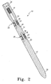
- FIG. 2 shows a cross-sectional view of the modular trial 10.
- the distal body 12 has a distal section 30 that is configured for implantation into a bone.
- the distal body 12 also has a proximal section 32.
- the proximal section 32 includes a non-threaded proximally extending protrusion 34, which in the embodiment shown in Fig. 2 is a pin.
- the pin includes a lip 36.
- other types of protrusions may be used.
- other types of shapes other than lips may be used.
- the pin 34 extends into a recess 38 of the middle body 14.
- the locking mechanism 22 of the middle body 14 is also at least partially disposed in the recess 38. As shown, the locking mechanism 22 engages the lip 36 of the pin 34.
- FIG. 3 is a perspective view of the locking mechanism 22 which has a first wall 40 and a second wall 42 opposite the first wall 40.
- Each of the first and second walls 40, 42 defines an interior groove or recess 44 that is sized and shaped to receive the pin 34.
- the wall 40, 42 forms a spiral-shaped edge 46.
- the spiral shaped edge 46 gradually spirals toward an edge of the wall 40, 42.
- FIG. 3 only one edge 46 is shown, it should be understood that the edge 46 may be formed in both walls 40, 42. Although in other embodiments, the edge 46 may only be formed in one of the two walls 40, 42. In other embodiments, the edge 46 may be cam-shaped. Alternatively, the edge 46 may be ramp-shaped.
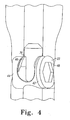
- the edge 46 engages the lip 36.
- the wall 40 includes a hex-shaped recess 48 for engaging a tool (not shown).
- the tool engages the recess 48 and works to turn the locking mechanism 22 from an unlocked to a locked position.
- the pin 34 fits within the groove 44.
- the lip 36 of the pin 34 engages the spiral edge 46. Because the edge 46 is spiral-shaped, the lip 36 rides along the edge 46 and is pulled closer to the edge of the wall 40, 42, pulling the pin 34 further into the recess 38. Once the locking mechanism 22 has been fully turned (in this case, through a quarter turn) the pin 34 is locked into the recess 38.
- the pin 34 has two lips 36, opposing one another (not shown).
- the locking mechanism 22 has two spiral-shaped edges 46, one for engaging each lip. As the locking mechanism 22 is turned, the lips 36 ride along the spiral edges 46, both toward the opposite edges of the walls 40, 42. This effectively locks the pin 34 in place.
- the distal section 18 of the middle body 14 includes at least one anti-rotation protrusion (or device) 49a.
- the anti-rotation protrusion 49a couples with an anti-rotation recess 49b on the proximal section of the distal body 12.
- the anti-rotation device and recess 49a, 49b keep the distal body 12 and middle body 14 from rotating relative to one another.
- the anti-rotation devices 49a may be of different sizes (as will be the anti-rotation recesses 49b) as this ensures that the distal body 12 will be inserted into the middle body 14 in the proper orientation.
- the distal body 12 may be so slightly bowed that it is difficult to recognize.
- the different sized anti-rotation devices and recesses 49a, 49b ensure that the bow is correctly positioned.
- the middle body 14 includes a protrusion and the distal body includes a recess. Other anti-rotation devices may be used.
- the middle body 14 may include a recess and the distal body 12 the protrusion.
- the connection between the proximal body 16 and the middle body 14 may also include anti-rotation devices 49a, 49b as illustrated. Other anti-rotation devices may also be used.
- the wall 42 is shown with indicia 51.
- the indicia 51 are used to indicate when the locking mechanism is locked.
- the indicium 51 is an arrow. When the arrow 51 points one way, the locking mechanism 22 is unlocked. When it points in a different direction, the locking mechanism 22 is locked.
- the walls 40, 42 may also have an irregularly curved outer shape. Thus, when the locking mechanism 22 is unlocked, the outer portion of the walls 40, 42 extend out past a side of the middle body 14. When the locking mechanism 22 is in a locked position, the outer portions of the walls 40, 42 are flush with the side of the middle body 14, allowing the trial 10 to replicate an implant.
- both indicia 51 and a curved shape may be used. In other embodiments, other indicating methods or no indicating methods may be used.
- the proximal section 20 of the middle body 14 includes a non-threaded proximally extending protrusion 52.
- the non-threaded proximally extending protrusion 52 of the middle body 14 is a pin - in fact, the same as the pin 34 of the distal body.
- the distal section 24 of the proximal body 16 includes a recess 54 and a locking mechanism 56.
- the recess 54 and locking mechanism 56 are the same as the recess 38 and locking mechanism 22 of the middle body 14.
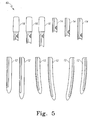
- FIG. 5 shows a trial system kit 60 which can include multiple sizes of each of the distal body 12, the middle body 14, and the proximal body 16. In some embodiments, there may be only one proximal body 16. As shown, the multiple sizes of the distal body 12 can include different lengths and different shapes. Some of the distal bodies 12, middle bodies 14, and proximal bodies 16 include straight distal portions while others have curved or bowed distal portions. Thus, different sizes and shapes of the distal body 12, middle body 14, and proximal body 16 can be mixed and matched with one another to produce a modular trial assembly 10 ( FIG. 1 ) that matches the size and shape of the patient's joint anatomy. Various trial assemblies may be tried in order to ascertain which final implant will work best, in the surgeon's judgment. Regardless of which combination of distal body 12, middle body 14, and proximal body 16 is used to assemble the modular trial 10, the manner of assembly, which will be discussed in detail herein, is substantially the same.
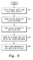
- FIG. 6 shows steps in a method for assembling the trial 10.
- a distal body 12, a middle body 14, and a proximal body 16 will be selected from the kit 60.
- the distal body 12, middle body 14, and proximal body 16 selected will be sized and shaped such that when they are connected, the trial will match the patient's anatomy.
- the pin 34 of the distal body 12 will be inserted into the recess 38 of the middle body 14 and locking mechanism 22.
- the locking mechanism 22 will be turned to lock the pin 34 into place (step s74).
- the user may decide to check using the indicia or other features (such as the shape of the locking mechanism 22) that the locking mechanism is fully locked.
- step s76 the pin 52 of the middle body is inserted into the recess 54 of the proximal body 16 and locking mechanism 56.
- the locking mechanism 56 is then turned to lock the pin 52 in place (step s78).
- the user may wish to check the indicia or other features to ensure that the locking mechanism 56 is locked.
- the trial 10 is then assembled. Steps s72 to s78 of the method may be performed in any order. It does not matter which pieces are coupled to one another first or if the pieces are locked prior to the next piece being added.
- the patient's anatomy may be such that the patient does not need all three bodies 12, 14, 16. In those cases, two of the bodies 12, 14, 16 may be used in any combination that best fits the patient's anatomy. In other embodiments, the patient's anatomy may require multiple middle bodies 14. In such cases, more than one middle body 14 may be used.
- the bodies 12, 14, 16 are made of a lightweight sterilisable material such as aluminium and the locking mechanisms 22, 56 are made using stainless steel.
- the locking mechanisms may also be made of aluminium or other sterilisable material.
- the bodies 12, 14, 16 may be made of other sterilisable material.
- the trial 10 may be made entirely of polymeric material.
- the embodiments above have all been described as forming a distal stem, it should be understood that the invention may include other trials.
- the same type of locking mechanism could be used with a distal stem connecting to a neck portion of a hip prosthesis.
- the distal body 12 could be a broach or other instrument that is attached to a middle body 14 or proximal body 16.
- the broach could be attached via the locking mechanism described to a neck portion.
Landscapes
- Health & Medical Sciences (AREA)
- Transplantation (AREA)
- Orthopedic Medicine & Surgery (AREA)
- Heart & Thoracic Surgery (AREA)
- Cardiology (AREA)
- Oral & Maxillofacial Surgery (AREA)
- Engineering & Computer Science (AREA)
- Biomedical Technology (AREA)
- Physical Education & Sports Medicine (AREA)
- Vascular Medicine (AREA)
- Life Sciences & Earth Sciences (AREA)
- Animal Behavior & Ethology (AREA)
- General Health & Medical Sciences (AREA)
- Public Health (AREA)
- Veterinary Medicine (AREA)
- Prostheses (AREA)
Abstract
Description
- This invention relates to a surgical trial instrument assembly and, more particularly, to a surgical trial instrument assembly for determining the required dimensions of a prosthetic femoral component.
- During the lifetime of a patient, it may be necessary to perform a joint replacement procedure or arthroplasty on the patient as a result of, for example, disease or trauma. One such type of joint replacement procedure is a hip replacement procedure in which a hip joint which is diseased or damaged or both is replaced with a hip joint prosthesis. A typical hip replacement procedure utilizes a prosthesis that generally includes a femoral stem component, a proximal body component, and a neck segment. The femoral stem is implanted in a prepared medullary canal of the patient's femur.
- During performance of such a hip replacement procedure, the surgeon must evaluate the size and condition of the patient's bones (e.g. the patient's femur) in order to determine the proper type and configuration of each of the various types of prosthetic components that are to be implanted. One or more provisional components are temporarily fixed to a bone prior to permanent fixation of the prosthetic joint. The provisional components are intended to mimic certain aspects of the permanent prosthetic joint in order for a surgeon to validate measurements and to test several different possible component sizes and shapes. Hence, provisional components are aptly known as "trials", and the procedure is known as "trialing".
- Currently, in a majority of revision total hip arthroplasties, the bone has little or no supportive metaphysis or diaphyseal areas. This makes it difficult for surgeons to reproduce the proper anatomy. To do this, the surgeon may use a distally fixed implant. This facilitates trialing from the distal femoral cortex and subsequent proximal anatomy. Many trials are used in surgery having one basic anterior/posterior proximal anatomical body with altering characteristics (i.e., stem lengths, bow, offsets, neck lengths, neck ante-version). Each instance requires a single monolithic trial that duplicates the implant, which is therein made from casting substrate. Some trialing techniques utilize the broach as the stem and then attach a proximal trial on to the broach.
- Other techniques require that the broach be removed from the medullary canal to allow the use of a trial having a stem portion, a head and a neck. For example, some have disclosed a system including a group of variously sized trial neck/body portions and a group of differing length trial stem portions which are mixed and matched to create a suitable trial. The trials are held together using a ball and spring detent system. Such ball and spring systems do not create a tight, wiggle-free connection. Because the trial pieces are not held tightly together, there can be errors in the use of the actual implant.
- Because many variations in sizes and shapes of trials are required to be available to the surgeon, it is necessary to maintain a large inventory of trials. Such a large inventory is costly, occupies valuable operating room space, and is difficult to manage. If the trial is a singular piece, then there must be upwards of 50 full trials. These full trials take up large amounts of space in instrument sets.
- In some modular trials, the different parts of the trial are assembled using threads. However, this makes connection and disconnection lengthy and cumbersome. In other modular trial designs, the different parts are held together by nothing more than a ball plunger of balseal. These features are not suitable for a solid, wiggle-free connection which resists tensile forces as well as rotational ones. Others use the reamer as the trial stem. However, not all distal reamers are suitable for working as trials.
- The present invention provides a modular prosthetic trial for a joint prosthesis. The trial includes a first piece having a proximal section and a distal section configured for implantation in a bone. The proximal section includes a non-threaded proximally extending protrusion. The trial also includes a second piece having a proximal section and a distal section, the distal section including a recess for receiving the non-threaded proximally extending protrusion. A locking mechanism is at least partially disposed within the recess of the second piece. The locking mechanism is sized and shaped to engage the protrusion such that the locking mechanism locks the first piece to the second piece.
- The modular trial can be assembled by a method which includes inserting a non-threaded proximally extending protrusion from a first piece into a corresponding recess in a distal portion of a second piece. The proximally extending protrusion engages a locking mechanism disposed in the second piece. The method further includes activating the locking mechanism to lock the first piece to the second piece.
- The invention also provides a kit for use in performing joint arthroplasty. The includes a plurality of first trial pieces having a proximal section and a distal section configured for implantation in a bone. The proximal section has a non-threaded proximally extending protrusion. The kit also includes a plurality of second trial pieces having a proximal section and a distal section. The distal section includes a recess for receiving the non-threaded proximally extending protrusion and the proximal section includes a non-threaded proximally extending protrusion. Each of the plurality of second trial pieces includes a locking mechanism at least partially disposed within the recess of the second trial piece. The locking mechanism is sized and shaped to engage the protrusion such that the locking mechanism locks the first trial piece to the second trial piece. The kit also includes a third trial piece that includes a proximal end and a distal end. The distal end includes a recess for receiving the non-threaded proximally extending protrusion of one of the plurality of second trial pieces, and the distal end includes a locking mechanism at least partially disposed within the recess of the third trial piece. The locking mechanism is sized and shaped to engage the protrusion such that the locking mechanism locks the second trial piece to the third trial piece.
- Embodiments of the invention are described below by way of example with reference to the accompanying drawings, in which:
-
FIG. 1 is a perspective view of a modular trial assembly. -
FIG. 2 is a partially cut-away view of the modular trial assembly ofFIG. 1 . -
FIG. 3 is a perspective view of a locking mechanism. -
FIG. 4 is a close-up view of the modular trial assembly ofFIG. 1 . -
FIG. 5 shows a kit of a plurality of modular trial assembly parts. -
FIG. 6 is a flow chart showing details of a method of assembling a modular trial assembly. - It should initially be appreciated that the trialing components provided by the present invention are intended for use after proper resection of a patient's proximal femur for evaluating the size and shape of an implant prior to committing to the final preparation of the proximal femur. The proximal end portion of the patient's femur can be resected by use of, for example, a bone saw (not shown). Known techniques can be used to resect the femur.
- Referring to the drawings,
FIG. 1 shows amodular trial assembly 10 which includes a first piece ordistal body 12, a second piece ormiddle body 14, and a third piece orproximal body 16. Each of the pieces makes up part of a distal stem. However, it should be appreciated that in other embodiments, the pieces may make up different parts of a different implant or trial. - As shown in
FIG. 1 , themiddle body 14 includes adistal section 18 and aproximal section 20. Thedistal section 18 includes alocking mechanism 22. Theproximal body 16 also includes adistal section 24 and aproximal section 26. Thedistal section 24 of theproximal body 16 also includes alocking mechanism 28. -
FIG. 2 shows a cross-sectional view of themodular trial 10. As shown, thedistal body 12 has adistal section 30 that is configured for implantation into a bone. Thedistal body 12 also has aproximal section 32. Theproximal section 32 includes a non-threadedproximally extending protrusion 34, which in the embodiment shown inFig. 2 is a pin. In this embodiment, the pin includes alip 36. In other embodiments, other types of protrusions may be used. Also, other types of shapes other than lips may be used. - As shown in
FIG. 2 , thepin 34 extends into arecess 38 of themiddle body 14. Thelocking mechanism 22 of themiddle body 14 is also at least partially disposed in therecess 38. As shown, thelocking mechanism 22 engages thelip 36 of thepin 34. -
FIG. 3 is a perspective view of thelocking mechanism 22 which has afirst wall 40 and asecond wall 42 opposite thefirst wall 40. Each of the first andsecond walls recess 44 that is sized and shaped to receive thepin 34. At an end of thegroove 44, thewall edge 46. The spiral shapededge 46 gradually spirals toward an edge of thewall FIG. 3 , only oneedge 46 is shown, it should be understood that theedge 46 may be formed in bothwalls edge 46 may only be formed in one of the twowalls edge 46 may be cam-shaped. Alternatively, theedge 46 may be ramp-shaped. - As shown in
FIG. 4 , theedge 46 engages thelip 36. Thewall 40 includes a hex-shapedrecess 48 for engaging a tool (not shown). The tool engages therecess 48 and works to turn thelocking mechanism 22 from an unlocked to a locked position. When thelocking mechanism 22 is in the unlocked position, thepin 34 fits within thegroove 44. As thelocking mechanism 22 is turned, thelip 36 of thepin 34 engages thespiral edge 46. Because theedge 46 is spiral-shaped, thelip 36 rides along theedge 46 and is pulled closer to the edge of thewall pin 34 further into therecess 38. Once thelocking mechanism 22 has been fully turned (in this case, through a quarter turn) thepin 34 is locked into therecess 38. - In some embodiments, the
pin 34 has twolips 36, opposing one another (not shown). In those embodiments, thelocking mechanism 22 has two spiral-shapededges 46, one for engaging each lip. As thelocking mechanism 22 is turned, thelips 36 ride along the spiral edges 46, both toward the opposite edges of thewalls pin 34 in place. - As shown in
FIG. 1 , thedistal section 18 of themiddle body 14 includes at least one anti-rotation protrusion (or device) 49a. Theanti-rotation protrusion 49a couples with ananti-rotation recess 49b on the proximal section of thedistal body 12. The anti-rotation device andrecess distal body 12 andmiddle body 14 from rotating relative to one another. In some embodiments, there are two anti-rotation devices and recesses 49a, 49b, one on each side of therespective body anti-rotation devices 49a may be of different sizes (as will be the anti-rotation recesses 49b) as this ensures that thedistal body 12 will be inserted into themiddle body 14 in the proper orientation. In some cases, thedistal body 12 may be so slightly bowed that it is difficult to recognize. The different sized anti-rotation devices and recesses 49a, 49b ensure that the bow is correctly positioned. In the described embodiment, themiddle body 14 includes a protrusion and the distal body includes a recess. Other anti-rotation devices may be used. Also, themiddle body 14 may include a recess and thedistal body 12 the protrusion. The connection between theproximal body 16 and themiddle body 14 may also includeanti-rotation devices - Returning now to
FIG. 3 , thewall 42 is shown withindicia 51. Theindicia 51 are used to indicate when the locking mechanism is locked. In this embodiment, theindicium 51 is an arrow. When thearrow 51 points one way, thelocking mechanism 22 is unlocked. When it points in a different direction, thelocking mechanism 22 is locked. In some embodiments, thewalls locking mechanism 22 is unlocked, the outer portion of thewalls middle body 14. When thelocking mechanism 22 is in a locked position, the outer portions of thewalls middle body 14, allowing thetrial 10 to replicate an implant. In some embodiments, bothindicia 51 and a curved shape may be used. In other embodiments, other indicating methods or no indicating methods may be used. - It is shown in
FIGS. 1 and2 that theproximal section 20 of themiddle body 14 includes a non-threadedproximally extending protrusion 52. In this embodiment, the non-threadedproximally extending protrusion 52 of themiddle body 14 is a pin - in fact, the same as thepin 34 of the distal body. Thedistal section 24 of theproximal body 16 includes a recess 54 and alocking mechanism 56. The recess 54 andlocking mechanism 56 are the same as therecess 38 andlocking mechanism 22 of themiddle body 14. -
FIG. 5 shows atrial system kit 60 which can include multiple sizes of each of thedistal body 12, themiddle body 14, and theproximal body 16. In some embodiments, there may be only oneproximal body 16. As shown, the multiple sizes of thedistal body 12 can include different lengths and different shapes. Some of thedistal bodies 12,middle bodies 14, andproximal bodies 16 include straight distal portions while others have curved or bowed distal portions. Thus, different sizes and shapes of thedistal body 12,middle body 14, andproximal body 16 can be mixed and matched with one another to produce a modular trial assembly 10 (FIG. 1 ) that matches the size and shape of the patient's joint anatomy. Various trial assemblies may be tried in order to ascertain which final implant will work best, in the surgeon's judgment. Regardless of which combination ofdistal body 12,middle body 14, andproximal body 16 is used to assemble themodular trial 10, the manner of assembly, which will be discussed in detail herein, is substantially the same. -
FIG. 6 shows steps in a method for assembling thetrial 10. At step s70, adistal body 12, amiddle body 14, and aproximal body 16 will be selected from thekit 60. Thedistal body 12,middle body 14, andproximal body 16 selected will be sized and shaped such that when they are connected, the trial will match the patient's anatomy. At step s72, thepin 34 of thedistal body 12 will be inserted into therecess 38 of themiddle body 14 andlocking mechanism 22. Thelocking mechanism 22 will be turned to lock thepin 34 into place (step s74). The user may decide to check using the indicia or other features (such as the shape of the locking mechanism 22) that the locking mechanism is fully locked. At step s76, thepin 52 of the middle body is inserted into the recess 54 of theproximal body 16 andlocking mechanism 56. Thelocking mechanism 56 is then turned to lock thepin 52 in place (step s78). As before with thelocking mechanism 22, the user may wish to check the indicia or other features to ensure that thelocking mechanism 56 is locked. Thetrial 10 is then assembled. Steps s72 to s78 of the method may be performed in any order. It does not matter which pieces are coupled to one another first or if the pieces are locked prior to the next piece being added. - In some embodiments, the patient's anatomy may be such that the patient does not need all three
bodies bodies middle bodies 14. In such cases, more than onemiddle body 14 may be used. - In one embodiment, the
bodies mechanisms bodies trial 10 may be made entirely of polymeric material. - Although the embodiments above have all been described as forming a distal stem, it should be understood that the invention may include other trials. For example, the same type of locking mechanism could be used with a distal stem connecting to a neck portion of a hip prosthesis. In other embodiments, the
distal body 12 could be a broach or other instrument that is attached to amiddle body 14 orproximal body 16. Alternatively, the broach could be attached via the locking mechanism described to a neck portion.
Claims (15)
- A modular prosthetic trial for a joint prosthesis, comprising:a first piece having a proximal section and a distal section configured for implantation in a bone, the proximal section having a non-threaded proximally extending protrusion;a second piece having a proximal section and a distal section, the distal section including a recess for receiving the non-threaded proximally extending protrusion; anda locking mechanism at least partially disposed within the recess of the second piece, the locking mechanism sized and shaped to engage the protrusion such that the locking mechanism locks the first piece to the second piece.
- The trial of claim 1, in which the non-threaded proximally extending protrusion is a pin having a first lip.
- The trial of claim 2, in which the locking mechanism includes a spirally shaped edge sized and shaped to engage the lip.
- The trial of claim 3, in which when the locking mechanism is in a locked position, and a thickest portion of the spiral edge engages the lip.
- The trial of claim 3, in which the locking mechanism includes a recess sized and shaped to receive the pin when the locking mechanism is in an unlocked position.
- The trial of claim 2, in which the pin has a second lip spaced from the first lip and the locking mechanism includes two spirally shaped edges, one of the spirally shaped edges engaging one of the first and second lips and the other of the spirally shaped edges engaging the other of the first and second lips.
- The trial of claim 1, in which said locking mechanism includes an instrument-engagement portion for receiving an instrument.
- The trial of claim 1, in which the proximal portion of the second piece includes a non-threaded proximally extending protrusion.
- The trial of claim 1, which includes:a third piece having a proximal end and a distal end, the distal end including a recess for receiving the non-threaded proximally extending protrusion; anda second locking mechanism at least partially disposed within the recess of the third piece, the locking mechanism sized and shaped to engage the protrusion such that the locking mechanism locks the second piece to the third piece.
- A kit for use in performing joint arthroplasty, which comprises:a plurality of first trial pieces having a proximal section and a distal section configured for implantation in a bone, the proximal section having a non-threaded proximally extending protrusion;a plurality of second trial pieces having a proximal section and a distal section, the distal section including a recess for receiving the non-threaded proximally extending protrusion and the proximal section including a non-threaded proximally extending protrusion, in which each of the plurality of second trial pieces includes a locking mechanism at least partially disposed within the recess of the second trial piece, the locking mechanism sized and shaped to engage the protrusion such that the locking mechanism locks the first trial piece to the second trial piece;a third trial piece, the third trial piece including a proximal end and a distal end, the distal end including a recess for receiving the non-threaded proximally extending protrusion of one of the plurality of second trial pieces, the distal end further including a locking mechanism at least partially disposed within the recess of the third trial piece, the locking mechanism sized and shaped to engage the protrusion such that the locking mechanism locks the second trial piece to the third trial piece.
- The kit of claim 10, in which each of the plurality of first trial pieces differ from one another in at least one of size and shape.
- The kit of claim 10, in which the plurality of second trial pieces differ from one another in size.
- The kit of claim 10, in which the locking mechanism of each of the second trial pieces and the locking mechanisms of the third trial piece have the same shape and the non-threaded proximally extending protrusion of each of the plurality of first pieces and the non-threaded proximally extending protrusion of each of the plurality of second pieces also have the same shape such that the third trial piece may be connected to one of the plurality of first trial pieces without one of the plurality of second trial pieces in-between.
- The kit of claim 10, in which locking mechanism of the plurality of second trial pieces and the locking mechanism of the third trial piece each have a spiral shaped edge and the non-threaded proximally extending protrusions of the plurality of first trial pieces and plurality of second trial pieces include a lip for engaging the spiral shaped edge.
- The kit of claim 10, which includes a wrench for engaging the locking mechanism of the plurality of second trial pieces and the third trial piece, such that when the wrench is turned, the locking mechanism locks assembled pieces together.
Applications Claiming Priority (1)
| Application Number | Priority Date | Filing Date | Title |
|---|---|---|---|
| US12/609,594 US8252002B2 (en) | 2009-10-30 | 2009-10-30 | Modular trial mechanism |
Publications (2)
| Publication Number | Publication Date |
|---|---|
| EP2316388A1 true EP2316388A1 (en) | 2011-05-04 |
| EP2316388B1 EP2316388B1 (en) | 2015-05-27 |
Family
ID=43530806
Family Applications (1)
| Application Number | Title | Priority Date | Filing Date |
|---|---|---|---|
| EP10187325.5A Active EP2316388B1 (en) | 2009-10-30 | 2010-10-12 | Modular trial mechanism |
Country Status (2)
| Country | Link |
|---|---|
| US (1) | US8252002B2 (en) |
| EP (1) | EP2316388B1 (en) |
Families Citing this family (9)
| Publication number | Priority date | Publication date | Assignee | Title |
|---|---|---|---|---|
| WO2008069800A1 (en) * | 2006-12-07 | 2008-06-12 | Anatol Podolsky | Method and apparatus for total hip replacement |
| US8974540B2 (en) | 2006-12-07 | 2015-03-10 | Ihip Surgical, Llc | Method and apparatus for attachment in a modular hip replacement or fracture fixation device |
| US8579985B2 (en) | 2006-12-07 | 2013-11-12 | Ihip Surgical, Llc | Method and apparatus for hip replacement |
| US9597203B2 (en) | 2015-03-25 | 2017-03-21 | Tornier, Inc. | Modular humeral implant |
| US10667850B2 (en) * | 2017-08-17 | 2020-06-02 | Spinal Generations, Llc | Modular femoral nail and method of use thereof |
| EP3498230B1 (en) * | 2017-12-15 | 2020-10-28 | Waldemar Link GmbH & Co. KG | Modular endoprosthesis shaft system with rotating element |
| US11202713B2 (en) | 2019-02-22 | 2021-12-21 | Howmedica Osteonics Corp. | Modular femoral trialing system having adjustable height |
| US11173050B2 (en) | 2019-02-22 | 2021-11-16 | Howmedica Osteonics Corp. | Modular femoral trialing system with temporary locking |
| US11311392B2 (en) | 2019-02-22 | 2022-04-26 | Howmedica Osteonics Corp. | Modular femoral trialing system permitting relative movement |
Citations (4)
| Publication number | Priority date | Publication date | Assignee | Title |
|---|---|---|---|---|
| EP0163121A1 (en) * | 1984-05-11 | 1985-12-04 | Waldemar Link (GmbH & Co.) | Arrangement for producing an endoprosthesis anatomically made to measure |
| WO2001082843A2 (en) * | 2000-05-03 | 2001-11-08 | Smith & Nephew, Inc. | Multi modular trialing system and instrumentation |
| US20030204262A1 (en) * | 2002-04-30 | 2003-10-30 | Ferguson Joe William | Quick disconnect orthopaedic trials |
| EP1639963A1 (en) * | 2004-09-24 | 2006-03-29 | DePuy Products, Inc. | Orthopaedic spacer |
Family Cites Families (11)
| Publication number | Priority date | Publication date | Assignee | Title |
|---|---|---|---|---|
| US5100407A (en) * | 1990-09-04 | 1992-03-31 | Pfizer Hospital Products Group, Inc. | Modular trial hip replacement system |
| EP0558203A1 (en) * | 1992-02-20 | 1993-09-01 | Wright Medical Technology, Inc. | Modular trial instrument with interlock mechanism |
| US5352227A (en) * | 1993-02-03 | 1994-10-04 | Howmedica Inc. | Intercalary device |
| WO1996000539A1 (en) | 1994-06-30 | 1996-01-11 | Howmedica, Inc. | Modular femoral trial hip replacement system |
| US5620445A (en) * | 1994-07-15 | 1997-04-15 | Brosnahan; Robert | Modular intramedullary nail |
| US5590975A (en) * | 1994-12-06 | 1997-01-07 | Horntvedt; Earl | Fastening assembly |
| US5645607A (en) * | 1995-03-02 | 1997-07-08 | Zimmer, Inc. | Hip stem provisional having adjustable neck offsets |
| US5860982A (en) * | 1997-03-26 | 1999-01-19 | Johnson & Johnson Professional, Inc. | Cemented calcar replacement varying height trial |
| US6395004B1 (en) * | 1997-11-14 | 2002-05-28 | Sulzer Orthopedics Inc. | Orthopedic trial prosthesis and saw guide instrument |
| US6126694A (en) * | 1999-03-05 | 2000-10-03 | Sulzer Orthopedics Inc. | Universal distal broach and stem trial |
| US7273499B2 (en) * | 2002-09-30 | 2007-09-25 | Depuy Products, Inc. | Modular trial mechanism |
-
2009
- 2009-10-30 US US12/609,594 patent/US8252002B2/en active Active
-
2010
- 2010-10-12 EP EP10187325.5A patent/EP2316388B1/en active Active
Patent Citations (4)
| Publication number | Priority date | Publication date | Assignee | Title |
|---|---|---|---|---|
| EP0163121A1 (en) * | 1984-05-11 | 1985-12-04 | Waldemar Link (GmbH & Co.) | Arrangement for producing an endoprosthesis anatomically made to measure |
| WO2001082843A2 (en) * | 2000-05-03 | 2001-11-08 | Smith & Nephew, Inc. | Multi modular trialing system and instrumentation |
| US20030204262A1 (en) * | 2002-04-30 | 2003-10-30 | Ferguson Joe William | Quick disconnect orthopaedic trials |
| EP1639963A1 (en) * | 2004-09-24 | 2006-03-29 | DePuy Products, Inc. | Orthopaedic spacer |
Also Published As
| Publication number | Publication date |
|---|---|
| EP2316388B1 (en) | 2015-05-27 |
| US8252002B2 (en) | 2012-08-28 |
| US20110106270A1 (en) | 2011-05-05 |
Similar Documents
| Publication | Publication Date | Title |
|---|---|---|
| EP2316388B1 (en) | Modular trial mechanism | |
| US20260069435A1 (en) | Revision knee arthroplasty methods and instruments | |
| US10143559B2 (en) | Stem for use in joint arthroplasty | |
| EP2077098B1 (en) | Modular trial mechanism | |
| CA2089734C (en) | Modular trial hip replacement system | |
| US8545511B2 (en) | Expandable reverse shoulder trial | |
| US6395004B1 (en) | Orthopedic trial prosthesis and saw guide instrument | |
| CN109152581B (en) | System and method for preparing a patient's femur in an orthopaedic joint replacement procedure | |
| US7198642B2 (en) | Orthopaedic spacer | |
| US20070050041A1 (en) | Orthopaedic implant stem component, joint component, and associated kit | |
| US20040254646A1 (en) | Provisional coupling mechanism | |
| CA2730564C (en) | Femoral head prosthesis | |
| EP3355834A1 (en) | Tibial prosthesis for tibia with varus resection | |
| WO2024263527A1 (en) | Orthopedic humeral tray and bearing designs and related instruments |
Legal Events
| Date | Code | Title | Description |
|---|---|---|---|
| PUAI | Public reference made under article 153(3) epc to a published international application that has entered the european phase |
Free format text: ORIGINAL CODE: 0009012 |
|
| AK | Designated contracting states |
Kind code of ref document: A1 Designated state(s): AL AT BE BG CH CY CZ DE DK EE ES FI FR GB GR HR HU IE IS IT LI LT LU LV MC MK MT NL NO PL PT RO RS SE SI SK SM TR |
|
| AX | Request for extension of the european patent |
Extension state: BA ME |
|
| 17P | Request for examination filed |
Effective date: 20111031 |
|
| GRAP | Despatch of communication of intention to grant a patent |
Free format text: ORIGINAL CODE: EPIDOSNIGR1 |
|
| RIC1 | Information provided on ipc code assigned before grant |
Ipc: A61F 2/46 20060101AFI20150127BHEP |
|
| INTG | Intention to grant announced |
Effective date: 20150227 |
|
| GRAS | Grant fee paid |
Free format text: ORIGINAL CODE: EPIDOSNIGR3 |
|
| GRAA | (expected) grant |
Free format text: ORIGINAL CODE: 0009210 |
|
| AK | Designated contracting states |
Kind code of ref document: B1 Designated state(s): AL AT BE BG CH CY CZ DE DK EE ES FI FR GB GR HR HU IE IS IT LI LT LU LV MC MK MT NL NO PL PT RO RS SE SI SK SM TR |
|
| REG | Reference to a national code |
Ref country code: GB Ref legal event code: FG4D |
|
| REG | Reference to a national code |
Ref country code: CH Ref legal event code: NV Representative=s name: E. BLUM AND CO. AG PATENT- UND MARKENANWAELTE , CH Ref country code: CH Ref legal event code: EP |
|
| REG | Reference to a national code |
Ref country code: AT Ref legal event code: REF Ref document number: 728423 Country of ref document: AT Kind code of ref document: T Effective date: 20150615 |
|
| REG | Reference to a national code |
Ref country code: IE Ref legal event code: FG4D |
|
| REG | Reference to a national code |
Ref country code: DE Ref legal event code: R096 Ref document number: 602010024870 Country of ref document: DE |
|
| REG | Reference to a national code |
Ref country code: AT Ref legal event code: MK05 Ref document number: 728423 Country of ref document: AT Kind code of ref document: T Effective date: 20150527 |
|
| REG | Reference to a national code |
Ref country code: LT Ref legal event code: MG4D |
|
| PG25 | Lapsed in a contracting state [announced via postgrant information from national office to epo] |
Ref country code: LT Free format text: LAPSE BECAUSE OF FAILURE TO SUBMIT A TRANSLATION OF THE DESCRIPTION OR TO PAY THE FEE WITHIN THE PRESCRIBED TIME-LIMIT Effective date: 20150527 Ref country code: NO Free format text: LAPSE BECAUSE OF FAILURE TO SUBMIT A TRANSLATION OF THE DESCRIPTION OR TO PAY THE FEE WITHIN THE PRESCRIBED TIME-LIMIT Effective date: 20150827 Ref country code: FI Free format text: LAPSE BECAUSE OF FAILURE TO SUBMIT A TRANSLATION OF THE DESCRIPTION OR TO PAY THE FEE WITHIN THE PRESCRIBED TIME-LIMIT Effective date: 20150527 Ref country code: HR Free format text: LAPSE BECAUSE OF FAILURE TO SUBMIT A TRANSLATION OF THE DESCRIPTION OR TO PAY THE FEE WITHIN THE PRESCRIBED TIME-LIMIT Effective date: 20150527 Ref country code: ES Free format text: LAPSE BECAUSE OF FAILURE TO SUBMIT A TRANSLATION OF THE DESCRIPTION OR TO PAY THE FEE WITHIN THE PRESCRIBED TIME-LIMIT Effective date: 20150527 Ref country code: PT Free format text: LAPSE BECAUSE OF FAILURE TO SUBMIT A TRANSLATION OF THE DESCRIPTION OR TO PAY THE FEE WITHIN THE PRESCRIBED TIME-LIMIT Effective date: 20150928 |
|
| REG | Reference to a national code |
Ref country code: NL Ref legal event code: MP Effective date: 20150527 |
|
| PG25 | Lapsed in a contracting state [announced via postgrant information from national office to epo] |
Ref country code: RS Free format text: LAPSE BECAUSE OF FAILURE TO SUBMIT A TRANSLATION OF THE DESCRIPTION OR TO PAY THE FEE WITHIN THE PRESCRIBED TIME-LIMIT Effective date: 20150527 Ref country code: AT Free format text: LAPSE BECAUSE OF FAILURE TO SUBMIT A TRANSLATION OF THE DESCRIPTION OR TO PAY THE FEE WITHIN THE PRESCRIBED TIME-LIMIT Effective date: 20150527 Ref country code: IS Free format text: LAPSE BECAUSE OF FAILURE TO SUBMIT A TRANSLATION OF THE DESCRIPTION OR TO PAY THE FEE WITHIN THE PRESCRIBED TIME-LIMIT Effective date: 20150927 Ref country code: LV Free format text: LAPSE BECAUSE OF FAILURE TO SUBMIT A TRANSLATION OF THE DESCRIPTION OR TO PAY THE FEE WITHIN THE PRESCRIBED TIME-LIMIT Effective date: 20150527 Ref country code: BG Free format text: LAPSE BECAUSE OF FAILURE TO SUBMIT A TRANSLATION OF THE DESCRIPTION OR TO PAY THE FEE WITHIN THE PRESCRIBED TIME-LIMIT Effective date: 20150827 Ref country code: GR Free format text: LAPSE BECAUSE OF FAILURE TO SUBMIT A TRANSLATION OF THE DESCRIPTION OR TO PAY THE FEE WITHIN THE PRESCRIBED TIME-LIMIT Effective date: 20150828 |
|
| PG25 | Lapsed in a contracting state [announced via postgrant information from national office to epo] |
Ref country code: DK Free format text: LAPSE BECAUSE OF FAILURE TO SUBMIT A TRANSLATION OF THE DESCRIPTION OR TO PAY THE FEE WITHIN THE PRESCRIBED TIME-LIMIT Effective date: 20150527 Ref country code: EE Free format text: LAPSE BECAUSE OF FAILURE TO SUBMIT A TRANSLATION OF THE DESCRIPTION OR TO PAY THE FEE WITHIN THE PRESCRIBED TIME-LIMIT Effective date: 20150527 |
|
| PG25 | Lapsed in a contracting state [announced via postgrant information from national office to epo] |
Ref country code: CZ Free format text: LAPSE BECAUSE OF FAILURE TO SUBMIT A TRANSLATION OF THE DESCRIPTION OR TO PAY THE FEE WITHIN THE PRESCRIBED TIME-LIMIT Effective date: 20150527 Ref country code: SK Free format text: LAPSE BECAUSE OF FAILURE TO SUBMIT A TRANSLATION OF THE DESCRIPTION OR TO PAY THE FEE WITHIN THE PRESCRIBED TIME-LIMIT Effective date: 20150527 Ref country code: RO Free format text: LAPSE BECAUSE OF NON-PAYMENT OF DUE FEES Effective date: 20150527 Ref country code: PL Free format text: LAPSE BECAUSE OF FAILURE TO SUBMIT A TRANSLATION OF THE DESCRIPTION OR TO PAY THE FEE WITHIN THE PRESCRIBED TIME-LIMIT Effective date: 20150527 |
|
| REG | Reference to a national code |
Ref country code: DE Ref legal event code: R097 Ref document number: 602010024870 Country of ref document: DE |
|
| PLBE | No opposition filed within time limit |
Free format text: ORIGINAL CODE: 0009261 |
|
| STAA | Information on the status of an ep patent application or granted ep patent |
Free format text: STATUS: NO OPPOSITION FILED WITHIN TIME LIMIT |
|
| PG25 | Lapsed in a contracting state [announced via postgrant information from national office to epo] |
Ref country code: IT Free format text: LAPSE BECAUSE OF FAILURE TO SUBMIT A TRANSLATION OF THE DESCRIPTION OR TO PAY THE FEE WITHIN THE PRESCRIBED TIME-LIMIT Effective date: 20150527 |
|
| 26N | No opposition filed |
Effective date: 20160301 |
|
| PG25 | Lapsed in a contracting state [announced via postgrant information from national office to epo] |
Ref country code: LU Free format text: LAPSE BECAUSE OF FAILURE TO SUBMIT A TRANSLATION OF THE DESCRIPTION OR TO PAY THE FEE WITHIN THE PRESCRIBED TIME-LIMIT Effective date: 20151012 Ref country code: SI Free format text: LAPSE BECAUSE OF FAILURE TO SUBMIT A TRANSLATION OF THE DESCRIPTION OR TO PAY THE FEE WITHIN THE PRESCRIBED TIME-LIMIT Effective date: 20150527 |
|
| PG25 | Lapsed in a contracting state [announced via postgrant information from national office to epo] |
Ref country code: MC Free format text: LAPSE BECAUSE OF FAILURE TO SUBMIT A TRANSLATION OF THE DESCRIPTION OR TO PAY THE FEE WITHIN THE PRESCRIBED TIME-LIMIT Effective date: 20150527 |
|
| PG25 | Lapsed in a contracting state [announced via postgrant information from national office to epo] |
Ref country code: BE Free format text: LAPSE BECAUSE OF FAILURE TO SUBMIT A TRANSLATION OF THE DESCRIPTION OR TO PAY THE FEE WITHIN THE PRESCRIBED TIME-LIMIT Effective date: 20150527 |
|
| REG | Reference to a national code |
Ref country code: FR Ref legal event code: PLFP Year of fee payment: 7 |
|
| PG25 | Lapsed in a contracting state [announced via postgrant information from national office to epo] |
Ref country code: SM Free format text: LAPSE BECAUSE OF FAILURE TO SUBMIT A TRANSLATION OF THE DESCRIPTION OR TO PAY THE FEE WITHIN THE PRESCRIBED TIME-LIMIT Effective date: 20150527 Ref country code: HU Free format text: LAPSE BECAUSE OF FAILURE TO SUBMIT A TRANSLATION OF THE DESCRIPTION OR TO PAY THE FEE WITHIN THE PRESCRIBED TIME-LIMIT; INVALID AB INITIO Effective date: 20101012 |
|
| PG25 | Lapsed in a contracting state [announced via postgrant information from national office to epo] |
Ref country code: SE Free format text: LAPSE BECAUSE OF FAILURE TO SUBMIT A TRANSLATION OF THE DESCRIPTION OR TO PAY THE FEE WITHIN THE PRESCRIBED TIME-LIMIT Effective date: 20150527 Ref country code: CY Free format text: LAPSE BECAUSE OF FAILURE TO SUBMIT A TRANSLATION OF THE DESCRIPTION OR TO PAY THE FEE WITHIN THE PRESCRIBED TIME-LIMIT Effective date: 20150527 Ref country code: NL Free format text: LAPSE BECAUSE OF FAILURE TO SUBMIT A TRANSLATION OF THE DESCRIPTION OR TO PAY THE FEE WITHIN THE PRESCRIBED TIME-LIMIT Effective date: 20150527 |
|
| PG25 | Lapsed in a contracting state [announced via postgrant information from national office to epo] |
Ref country code: TR Free format text: LAPSE BECAUSE OF FAILURE TO SUBMIT A TRANSLATION OF THE DESCRIPTION OR TO PAY THE FEE WITHIN THE PRESCRIBED TIME-LIMIT Effective date: 20150527 Ref country code: MT Free format text: LAPSE BECAUSE OF FAILURE TO SUBMIT A TRANSLATION OF THE DESCRIPTION OR TO PAY THE FEE WITHIN THE PRESCRIBED TIME-LIMIT Effective date: 20150527 |
|
| REG | Reference to a national code |
Ref country code: FR Ref legal event code: PLFP Year of fee payment: 8 |
|
| PG25 | Lapsed in a contracting state [announced via postgrant information from national office to epo] |
Ref country code: MK Free format text: LAPSE BECAUSE OF FAILURE TO SUBMIT A TRANSLATION OF THE DESCRIPTION OR TO PAY THE FEE WITHIN THE PRESCRIBED TIME-LIMIT Effective date: 20150527 |
|
| REG | Reference to a national code |
Ref country code: FR Ref legal event code: PLFP Year of fee payment: 9 |
|
| PG25 | Lapsed in a contracting state [announced via postgrant information from national office to epo] |
Ref country code: AL Free format text: LAPSE BECAUSE OF FAILURE TO SUBMIT A TRANSLATION OF THE DESCRIPTION OR TO PAY THE FEE WITHIN THE PRESCRIBED TIME-LIMIT Effective date: 20150527 |
|
| PGFP | Annual fee paid to national office [announced via postgrant information from national office to epo] |
Ref country code: GB Payment date: 20250828 Year of fee payment: 16 |
|
| PGFP | Annual fee paid to national office [announced via postgrant information from national office to epo] |
Ref country code: FR Payment date: 20250908 Year of fee payment: 16 |
|
| PGFP | Annual fee paid to national office [announced via postgrant information from national office to epo] |
Ref country code: IE Payment date: 20250909 Year of fee payment: 16 |
|
| REG | Reference to a national code |
Ref country code: CH Ref legal event code: U11 Free format text: ST27 STATUS EVENT CODE: U-0-0-U10-U11 (AS PROVIDED BY THE NATIONAL OFFICE) Effective date: 20251101 |
|
| PGFP | Annual fee paid to national office [announced via postgrant information from national office to epo] |
Ref country code: DE Payment date: 20250902 Year of fee payment: 16 |
|
| PGFP | Annual fee paid to national office [announced via postgrant information from national office to epo] |
Ref country code: CH Payment date: 20251101 Year of fee payment: 16 |