EP2316376A1 - Applicator for self-expanding intravaginal urinary incontinence devices - Google Patents
Applicator for self-expanding intravaginal urinary incontinence devices Download PDFInfo
- Publication number
- EP2316376A1 EP2316376A1 EP10251884A EP10251884A EP2316376A1 EP 2316376 A1 EP2316376 A1 EP 2316376A1 EP 10251884 A EP10251884 A EP 10251884A EP 10251884 A EP10251884 A EP 10251884A EP 2316376 A1 EP2316376 A1 EP 2316376A1
- Authority
- EP
- European Patent Office
- Prior art keywords
- barrel
- section
- applicator
- polymeric material
- self
- Prior art date
- Legal status (The legal status is an assumption and is not a legal conclusion. Google has not performed a legal analysis and makes no representation as to the accuracy of the status listed.)
- Granted
Links
- 206010046543 Urinary incontinence Diseases 0.000 title claims abstract description 30
- 238000003780 insertion Methods 0.000 claims abstract description 103
- 230000037431 insertion Effects 0.000 claims abstract description 103
- 238000000034 method Methods 0.000 claims abstract description 8
- 239000000463 material Substances 0.000 claims description 60
- 229920000092 linear low density polyethylene Polymers 0.000 claims description 14
- 239000004707 linear low-density polyethylene Substances 0.000 claims description 14
- -1 polypropylene Polymers 0.000 claims description 14
- 229920001684 low density polyethylene Polymers 0.000 claims description 12
- 239000004702 low-density polyethylene Substances 0.000 claims description 12
- 239000004743 Polypropylene Substances 0.000 claims description 11
- 229920001155 polypropylene Polymers 0.000 claims description 11
- 229920001903 high density polyethylene Polymers 0.000 claims description 8
- 239000004700 high-density polyethylene Substances 0.000 claims description 8
- 229920002725 thermoplastic elastomer Polymers 0.000 claims description 8
- 229930040373 Paraformaldehyde Natural products 0.000 claims description 4
- 229920006324 polyoxymethylene Polymers 0.000 claims description 4
- 239000004952 Polyamide Substances 0.000 claims description 3
- 239000004793 Polystyrene Substances 0.000 claims description 3
- 239000004676 acrylonitrile butadiene styrene Substances 0.000 claims description 3
- 238000004519 manufacturing process Methods 0.000 claims description 3
- 229920002647 polyamide Polymers 0.000 claims description 3
- 229920002223 polystyrene Polymers 0.000 claims description 3
- XECAHXYUAAWDEL-UHFFFAOYSA-N acrylonitrile butadiene styrene Chemical compound C=CC=C.C=CC#N.C=CC1=CC=CC=C1 XECAHXYUAAWDEL-UHFFFAOYSA-N 0.000 claims 2
- 229920000122 acrylonitrile butadiene styrene Polymers 0.000 claims 2
- 210000001215 vagina Anatomy 0.000 description 14
- 206010021639 Incontinence Diseases 0.000 description 8
- 238000012360 testing method Methods 0.000 description 6
- 230000000052 comparative effect Effects 0.000 description 5
- 229920003023 plastic Polymers 0.000 description 5
- 239000004033 plastic Substances 0.000 description 5
- 229920010126 Linear Low Density Polyethylene (LLDPE) Polymers 0.000 description 3
- 239000004698 Polyethylene Substances 0.000 description 3
- 229920000573 polyethylene Polymers 0.000 description 3
- 230000032683 aging Effects 0.000 description 2
- 230000006835 compression Effects 0.000 description 2
- 238000007906 compression Methods 0.000 description 2
- 229920001577 copolymer Polymers 0.000 description 2
- 238000005259 measurement Methods 0.000 description 2
- 239000012748 slip agent Substances 0.000 description 2
- 230000002485 urinary effect Effects 0.000 description 2
- 229920002943 EPDM rubber Polymers 0.000 description 1
- 241001313288 Labia Species 0.000 description 1
- 239000004677 Nylon Substances 0.000 description 1
- 230000002745 absorbent Effects 0.000 description 1
- 239000002250 absorbent Substances 0.000 description 1
- 239000000654 additive Substances 0.000 description 1
- 230000000996 additive effect Effects 0.000 description 1
- 239000000853 adhesive Substances 0.000 description 1
- 230000001070 adhesive effect Effects 0.000 description 1
- 238000004873 anchoring Methods 0.000 description 1
- 239000008280 blood Substances 0.000 description 1
- 210000004369 blood Anatomy 0.000 description 1
- 238000010276 construction Methods 0.000 description 1
- 238000007796 conventional method Methods 0.000 description 1
- 238000005520 cutting process Methods 0.000 description 1
- 238000002347 injection Methods 0.000 description 1
- 239000007924 injection Substances 0.000 description 1
- 238000001746 injection moulding Methods 0.000 description 1
- 235000015110 jellies Nutrition 0.000 description 1
- 239000008274 jelly Substances 0.000 description 1
- 238000005461 lubrication Methods 0.000 description 1
- 230000002175 menstrual effect Effects 0.000 description 1
- 238000012986 modification Methods 0.000 description 1
- 230000004048 modification Effects 0.000 description 1
- HLXZNVUGXRDIFK-UHFFFAOYSA-N nickel titanium Chemical compound [Ti].[Ti].[Ti].[Ti].[Ti].[Ti].[Ti].[Ti].[Ti].[Ti].[Ti].[Ni].[Ni].[Ni].[Ni].[Ni].[Ni].[Ni].[Ni].[Ni].[Ni].[Ni].[Ni].[Ni].[Ni] HLXZNVUGXRDIFK-UHFFFAOYSA-N 0.000 description 1
- 229910001000 nickel titanium Inorganic materials 0.000 description 1
- 229920001778 nylon Polymers 0.000 description 1
- 239000000088 plastic resin Substances 0.000 description 1
- 229920001296 polysiloxane Polymers 0.000 description 1
- 238000012552 review Methods 0.000 description 1
- 238000003860 storage Methods 0.000 description 1
- 229920000468 styrene butadiene styrene block copolymer Polymers 0.000 description 1
- 239000012815 thermoplastic material Substances 0.000 description 1
- 238000003466 welding Methods 0.000 description 1
Images

Classifications
-
- A—HUMAN NECESSITIES
- A61—MEDICAL OR VETERINARY SCIENCE; HYGIENE
- A61F—FILTERS IMPLANTABLE INTO BLOOD VESSELS; PROSTHESES; DEVICES PROVIDING PATENCY TO, OR PREVENTING COLLAPSING OF, TUBULAR STRUCTURES OF THE BODY, e.g. STENTS; ORTHOPAEDIC, NURSING OR CONTRACEPTIVE DEVICES; FOMENTATION; TREATMENT OR PROTECTION OF EYES OR EARS; BANDAGES, DRESSINGS OR ABSORBENT PADS; FIRST-AID KITS
- A61F2/00—Filters implantable into blood vessels; Prostheses, i.e. artificial substitutes or replacements for parts of the body; Appliances for connecting them with the body; Devices providing patency to, or preventing collapsing of, tubular structures of the body, e.g. stents
- A61F2/0004—Closure means for urethra or rectum, i.e. anti-incontinence devices or support slings against pelvic prolapse
- A61F2/0031—Closure means for urethra or rectum, i.e. anti-incontinence devices or support slings against pelvic prolapse for constricting the lumen; Support slings for the urethra
- A61F2/005—Closure means for urethra or rectum, i.e. anti-incontinence devices or support slings against pelvic prolapse for constricting the lumen; Support slings for the urethra with pressure applied to urethra by an element placed in the vagina
-
- A—HUMAN NECESSITIES
- A61—MEDICAL OR VETERINARY SCIENCE; HYGIENE
- A61F—FILTERS IMPLANTABLE INTO BLOOD VESSELS; PROSTHESES; DEVICES PROVIDING PATENCY TO, OR PREVENTING COLLAPSING OF, TUBULAR STRUCTURES OF THE BODY, e.g. STENTS; ORTHOPAEDIC, NURSING OR CONTRACEPTIVE DEVICES; FOMENTATION; TREATMENT OR PROTECTION OF EYES OR EARS; BANDAGES, DRESSINGS OR ABSORBENT PADS; FIRST-AID KITS
- A61F13/00—Bandages or dressings; Absorbent pads
- A61F13/15—Absorbent pads, e.g. sanitary towels, swabs or tampons for external or internal application to the body; Supporting or fastening means therefor; Tampon applicators
- A61F13/20—Tampons, e.g. catamenial tampons; Accessories therefor
- A61F13/2082—Apparatus or processes of manufacturing
- A61F13/2085—Catamenial tampons
- A61F13/2097—Catamenial tampons method of manufacturing tampon applicators
-
- A—HUMAN NECESSITIES
- A61—MEDICAL OR VETERINARY SCIENCE; HYGIENE
- A61F—FILTERS IMPLANTABLE INTO BLOOD VESSELS; PROSTHESES; DEVICES PROVIDING PATENCY TO, OR PREVENTING COLLAPSING OF, TUBULAR STRUCTURES OF THE BODY, e.g. STENTS; ORTHOPAEDIC, NURSING OR CONTRACEPTIVE DEVICES; FOMENTATION; TREATMENT OR PROTECTION OF EYES OR EARS; BANDAGES, DRESSINGS OR ABSORBENT PADS; FIRST-AID KITS
- A61F13/00—Bandages or dressings; Absorbent pads
- A61F13/15—Absorbent pads, e.g. sanitary towels, swabs or tampons for external or internal application to the body; Supporting or fastening means therefor; Tampon applicators
- A61F13/20—Tampons, e.g. catamenial tampons; Accessories therefor
- A61F13/26—Means for inserting tampons, i.e. applicators
-
- A—HUMAN NECESSITIES
- A61—MEDICAL OR VETERINARY SCIENCE; HYGIENE
- A61F—FILTERS IMPLANTABLE INTO BLOOD VESSELS; PROSTHESES; DEVICES PROVIDING PATENCY TO, OR PREVENTING COLLAPSING OF, TUBULAR STRUCTURES OF THE BODY, e.g. STENTS; ORTHOPAEDIC, NURSING OR CONTRACEPTIVE DEVICES; FOMENTATION; TREATMENT OR PROTECTION OF EYES OR EARS; BANDAGES, DRESSINGS OR ABSORBENT PADS; FIRST-AID KITS
- A61F13/00—Bandages or dressings; Absorbent pads
- A61F13/15—Absorbent pads, e.g. sanitary towels, swabs or tampons for external or internal application to the body; Supporting or fastening means therefor; Tampon applicators
- A61F13/20—Tampons, e.g. catamenial tampons; Accessories therefor
- A61F13/26—Means for inserting tampons, i.e. applicators
- A61F13/266—Insertion devices, e.g. rods or plungers, separate from the tampon
-
- B—PERFORMING OPERATIONS; TRANSPORTING
- B29—WORKING OF PLASTICS; WORKING OF SUBSTANCES IN A PLASTIC STATE IN GENERAL
- B29C—SHAPING OR JOINING OF PLASTICS; SHAPING OF MATERIAL IN A PLASTIC STATE, NOT OTHERWISE PROVIDED FOR; AFTER-TREATMENT OF THE SHAPED PRODUCTS, e.g. REPAIRING
- B29C45/00—Injection moulding, i.e. forcing the required volume of moulding material through a nozzle into a closed mould; Apparatus therefor
- B29C45/16—Making multilayered or multicoloured articles
- B29C45/1676—Making multilayered or multicoloured articles using a soft material and a rigid material, e.g. making articles with a sealing part
- B29C2045/1678—Making multilayered or multicoloured articles using a soft material and a rigid material, e.g. making articles with a sealing part first moulding the soft material
Definitions
- the present invention relates to an applicator suitable for intravaginal devices.
- the applicator is useful for placing the device in the vagina in the correct position to enable the device to function.
- the applicator is designed to be used with self-expanding intravaginal urinary incontinence devices.
- Tampons are absorbent articles that are inserted into a woman's vagina to absorb blood and other menstrual discharges.
- Intravaginal urinary incontinence devices are inserted into a woman's vagina to reduce or inhibit urinary incontinence.
- Applicators may be used to ease the insertion of both urinary incontinence devices and tampons.
- Applicators typically include a generally cylindrical barrel for holding the tampon or device and placing in the vagina. The barrel may also include what are commonly called petals at the insertion end.
- Petals are flexible flaps that go from a "closed” or rounded configuration to an "open” configuration which allows the contained tampon or device to be expelled from the barrel.
- the applicator also includes a plunger for expelling the device or tampon into the vagina.
- Cardboard and plastic applicators are known in the art.
- disposable plastic applicators are utilized to deliver tampons inside the vagina.
- Disposable applicators for tampons typically utilize a single plastic resin construction.
- some tampon applicators have considered the use of combinations of plastic materials.
- Williams et al., US Pat. No. 5681894 describes a tampon applicator barrel made up of linear low density polyethylene and styrene-butadiene-styrene block copolymer to provide comfort and ease of insertion.
- intravaginal urinary incontinence devices vary significantly from tampons.
- self-expanding intravaginal urinary incontinence devices may exert significant forces on the applicator containing them, so the choice of materials used to make the applicators may be significantly restricted.
- Intravaginal incontinence devices are designed to exert significant pressure within a user's vagina to support an adjacent urinary system. Prior to use, the device may be contained within an applicator for delivery into a vagina. Therefore, designers have had to modify the intravaginal urinary incontinence devices to minimize the distorting forces that may be exerted upon the device applicator. For example, Ziv, US Pub. Pat. App. 2007/0203429 discloses an intravaginal urinary incontinence device that must be "activated” or manually expanded after insertion to provide the force necessary to support the urinary system.
- the applicator strength must be increased to oppose the distorting forces of a self-expanding intravaginal urinary incontinence device. Because such a device may be in a constricted configuration, it is important that the applicator be able to withstand the pressure exerted by the incontinence device over an extended period of time (prior to use). However, such a modification may make it difficult or impossible to provide a closed insertion end with petals that are flexible enough to permit the expulsion of the device without too much force.
- an applicator for a self-expanding intravaginal device having a barrel and a plunger can substantially contain the self-expanding intravaginal device without significant insertion barrel distortion while maintaining comfortable applicator insertion.
- the barrel has an insertion end, an opposed gripper end, and a central portion therebetween, and it is arranged and configured to substantially contain the self-expanding intravaginal device.
- the plunger is in telescoping relation with the barrel, and it is arranged and configured to expel the self-expanding intravaginal device out of the insertion end of the barrel when the plunger is pushed into the gripper end of the barrel.
- a plurality of flexible petals substantially closes the insertion end of the barrel, and the central portion of the barrel has a load to 3 mm deflection of at least about 15 Newtons.
- a self-expanding intravaginal urinary incontinence system in another aspect of the invention includes a self-expanding intravaginal urinary incontinence device and an applicator substantially containing the self-expanding intravaginal urinary incontinence device.
- the applicator has a plunger in telescoping relation with a barrel having an insertion end, an opposed gripper end, and a central portion therebetween.
- a plurality of flexible petals substantially closes the insertion end of the barrel, and the central portion of the barrel has a load to 3 mm deflection of at least about 15 Newtons.
- a method of making an insertion barrel for an applicator for a self-expanding intravaginal device includes the steps of:
- a method of making an insertion barrel for an applicator for a self-expanding intravaginal device includes the steps of:
- the present invention relates to self-expanding intravaginal urinary incontinence system that includes a self-expanding intravaginal urinary incontinence device and an applicator for delivering the device.
- the applicator includes a barrel to substantially contain the device and a plunger in telescoping relation with the barrel to expel the device from the insertion end of the barrel. Because the self-expanding intravaginal urinary incontinence device may exert significant forces on the applicator containing them, the choice of materials used to make the applicators may be significantly restricted. Further, materials useful to provide an applicator barrel that resists distortion caused by the force exterted by the incontinence device may be too stiff to provide a closed insertion end with petals that are flexible enough to permit the expulsion of the device without excessive force.
- an applicator barrel having sufficient rigidity with substantially thinned insertion end petals that are flexible enough for reasonable expulsion of the incontinence device may be provided.
- a relatively rigid material may be used in a central portion of the barrel to withstand the forces exerted by the self-expanding intravaginal urinary incontinence device on the barrel, and another, relatively flexible material may be used to form the petals that substantially close the insertion end of the applicator barrel.
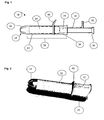
- Fig. 1 shows one embodiment of the present invention.
- Applicator 10 includes an elongate insertion barrel 12 and a plunger 14.
- the insertion barrel 12 is arranged and configured to substantially contain the self-expanding intravaginal urinary incontinence device 16.
- the insertion barrel has an insertion end 18, an opposed gripper end 20, and a central portion 22, therebetween.
- the insertion barrel 12 includes a first section 24 including the insertion end 18 of the barrel 12. This section may be formed of a relatively flexible material to form the petals 26 that substantially close the insertion end 18 of the applicator barrel 12.
- a second section 28 including the gripper end 20 and the central portion 22 of the insertion barrel 12 abuts the first section 24.
- This second section 28 may be formed of a relatively rigid material to withstand the forces exerted by the self-expanding intravaginal urinary incontinence device 16.
- the length of the barrel 12 may range from about 20 mm to 100 mm.
- the outer diameter of the barrel may range from about 5 mm to 25 mm for comfortable insertion into the vagina.
- the thickness of the barrel wall is sufficient to withstand the pressure exerted by the device, and may range, for example, from about 0.5 mm to 2 mm.
- the urinary incontinence device can be loaded into either end of the barrel prior to final assembly of the applicator 10.
- the insertion end 18 has petals 26 for easing insertion of the applicator and for retaining the device until deployment.
- the first section 24, including the insertion end 18, is separate from the first section 24.
- the first section 24 and the second section 28 are different materials but are integrally formed with no distinct parts, such as by overmolding.
- the terms "flexible material” shall mean a material that has a sufficient flexibility to permit easy expulsion of the contained self-expanding intravaginal urinary incontinence device from the applicator.
- a flexible material has a lower flexural modulus than the rigid material described below.
- the term "rigid material” shall mean a structural material that provides a central portion of the insertion barrel with sufficient stiffness to resist significant distortion under a load of a contained self-expanding intravaginal urinary incontinence device.
- a significant measure of the barrel stiffness is the "load to 3 mm deflection" as measured in the Barrel Stiffness Test described below.
- the barrel stiffness test is used to determine the force required to compress an applicator barrel by a fixed distance of 3 mm, the "load to 3 mm deflection.”
- the applicator barrel samples are prepared by cutting off the petals and finger grip end, creating a cylinder approximately 1.5 - 2" in length.
- the sample is then held between two 4 x 4" compression plates.
- the bottom plate is fixed at the base, and the other plate is attached to the moving crosshead.
- the top compression plate is brought down until it touches the sample. This is set as the zero position.
- the top plate compresses the sample by a distance of 3 mm, and at a rate of approximately 2 inches (50.8 mm) per minute, and the resistive force is recorded.
- the insertion barrel 12 preferably includes two different plastic materials - the first section 24 including the insertion end 18 and its petals 26 formed of a relatively flexible polymeric material - and the first section 24, comprised of a relatively rigid polymeric material.
- a representative, non-limiting list of useful flexible polymeric materials includes as Low Density Polyethylene (LDPE), Linear Low Density Polyethylene (LLDPE), Thermoplastic Elastomers (TPE) and combinations thereof.
- a representative, non-limiting list of useful rigid polymeric materials includes acrylonitrile-butadiene-styrene (ABS), High Density Polyethylene (HDPE), Linear Low Density Polyethylene (LLDPE), Polypropylene (PP), Polyamide (nylon or PA), Polyoxymethylene (POM), polystyrene, and combinations thereof.
- ABS acrylonitrile-butadiene-styrene
- HDPE High Density Polyethylene
- LLDPE Linear Low Density Polyethylene
- PP Polypropylene
- Polyamide polyamide
- POM Polyoxymethylene
- the flexible polymeric material has a lower flexural modulus than the relatively rigid polymeric material. This provides the flexibility useful to form comfortable petals in the first section and the stiffness useful to provide the rigidity in the central portion.
- the rigid polymeric material provides a rigid central portion 22 of the insertion barrel 12.
- the insertion barrel 12 has a load to 3 mm deflection of at least about 15 Newtons, more preferably at least about 20 Newtons, and most preferably, at east about 30 Newtons, and most, most preferably, at least about 40 Newtons.
- Figures 2-4 shows in greater detail the barrel of the present invention.
- the barrel 12 can be formed of a first section 24 including the insertion end 18, which is then attached to the second section 28.
- One way of attaching the first and second sections 24, 28 is by way of mechanical fit.
- holes 30 spaced away from the insertion end 18 engage protuberances 32 on the inner surface of the first section 24 to provide a mechanical fit between the two different sections.
- Other methods such as ultrasonic welding may also be used to secure the two sections together.
- the applicator barrel is made by two-step injection molding (or overmolding) of two different compatible polymeric materials to provide a secure attachment of the sections.
- a first shot of a flexible material such as LDPE
- a second shot of a more rigid material such as a LLDPE
- the first shot is of the more rigid material to form the central portion and finger grip end
- the second shot of the flexible material is overmolded to form the insertion end.
- Applicators according to the present invention also include a deployment plunger 14, an elongate device designed to fit in a telescoping manner within the barrel 12.
- the plunger 14 has a leading end 34 to bear against and to deploy the incontinence device 16 and an opposite end 36 having a stop 38 to prevent the plunger from being pushed too far and to ensure proper placement of the device in the vagina.
- the plunger 14 is moved axially into the insertion barrel 12 in a telescoping manner to deploy the device 16 from the insertion end 18 into the vagina.
- the plunger 14 may be made from any suitable material.
- the plunger may be molded from conventional thermoplastic materials such as, but not limited to, polyethylene (including without limitation HDPE, LDPE, LLDPE, etc.), polypropylene and a variety of copolymers. It is important that the plunger be strong enough to expel the incontinence device from the barrel without buckling.
- polyethylene including without limitation HDPE, LDPE, LLDPE, etc.
- polypropylene and a variety of copolymers. It is important that the plunger be strong enough to expel the incontinence device from the barrel without buckling.
- An insertion depth indicator 40 may be a raised element on the insertion barrel surface, oriented generally perpendicular to the longitudinal axis of the insertion barrel (and thus, the direction of insertion). This provides a tactile feedback when the insertion is completed.
- the height of the insertion depth indicator may range from 2 mm to 20 mm.
- the insertion depth indicator may be made from any suitable material, such as polyethylene, polypropylene, a variety of copolymers, silicone, and elastomeric materials, such as ethylene propylenediene monomer and the like.
- the insertion depth indicator may be molded into the barrel or may be formed separately and attached to the applicator through conventional methods, such as adhesives, friction fits and the like. The insertion depth indicator is positioned such that the device is deployed in the proper position within the vagina.
- Applicators according to the present invention may also include an orientation indicator 42 (also shown in Figures 2-3 ).
- the orientation indicator 42 may be helpful to place the incontinence device 16 in the vagina such that when it is deployed, the portion of the device that applies pressure, exerts pressure on the urethro-vesical junction, and any anchoring members lie on the lateral sides of the vagina.
- the orientation indicator 42 may clearly mark the orientation of the device within the applicator 10.
- the indicator 42 may be a raised line, a colored line, dots, embossments, or any suitable mark or shape that indicates orientation.
- the orientation indicator may be on any or all of a conventional finger grip, the insertion depth indicator, and the barrel 12 itself.
- the device is aligned with the orientation indicator when it is within the applicator, then it will be aligned to the body after insertion.
- the orientation indicator 42 is part of the insertion depth indicator 40, the orientation indicator 42 may be part of the shape of the insertion depth indicator 40.
- Suitable urinary incontinence devices for use with the applicators of the present invention include, but are not limited to, devices taught in co-pending US Patent Applications, US Publication No. 20080009662 A1 ; US Publication No. 20080033230 A1 ; US Publication No. 20080009931 A1 ; US Publication No. 20080009814 A1 ; US Publication No. 20080009663 A1 ; US Publication No. 20080033231 A1 ; US Publication No. 20080009664 A1 ; and US Publication No. 20080009666 A1 .
- the second section of the barrel according to Fig. 2 was molded out of polypropylene (PP) and the first section including the insertion end and the petals according to Fig. 4 , was molded out of low-density polyethylene (LDPE).
- Deployment plunger according to FIG. 1 was molded out of linear low-density polyethylene (LLDPE) with a 1% modified polyethylene slip additive.
- LLDPE linear low-density polyethylene
- the petals were then affixed onto the barrel using conventional mechanical fastening methods.
- the collar and finger grip components also utilized single cavity injection molds. A finger-grip sleeve and the insertion depth indicator collar were both designed to be friction fit attached to the applicator.
- the material utilized was a 65-durometer thermoplastic elastomer under the trade name of C-flex.
- the collar and the finger grip were both fit to the barrel such that they could be slid to different positions on the barrel that were associated with a woman's depth of labia associated with
- a use test was performed with 23 women to evaluate the level of comfort of the applicator of the 2-component applicator product.
- the women were given the applicator, lubrication (KY® Jelly), and a set of insertion and removal instructions.
- the women inserted the applicator after reading the instructions and then removed the applicator, leaving the tampon product inside their body.
- the tampon product was used in replacement for the intravaginal incontinence device.
- the women then filled out a questionnaire about the applicator (comfort, ergonomics, petal pinching, etc.). A one-on-one interview was then conducted to review their comments.
Landscapes
- Health & Medical Sciences (AREA)
- Engineering & Computer Science (AREA)
- Urology & Nephrology (AREA)
- Animal Behavior & Ethology (AREA)
- Public Health (AREA)
- Veterinary Medicine (AREA)
- Biomedical Technology (AREA)
- Heart & Thoracic Surgery (AREA)
- Vascular Medicine (AREA)
- Life Sciences & Earth Sciences (AREA)
- General Health & Medical Sciences (AREA)
- Manufacturing & Machinery (AREA)
- Epidemiology (AREA)
- Cardiology (AREA)
- Transplantation (AREA)
- Oral & Maxillofacial Surgery (AREA)
- Absorbent Articles And Supports Therefor (AREA)
- Materials For Medical Uses (AREA)
- Prostheses (AREA)
- Orthopedics, Nursing, And Contraception (AREA)
Abstract
Description
- The present invention relates to an applicator suitable for intravaginal devices. The applicator is useful for placing the device in the vagina in the correct position to enable the device to function. The applicator is designed to be used with self-expanding intravaginal urinary incontinence devices.
- Tampons are absorbent articles that are inserted into a woman's vagina to absorb blood and other menstrual discharges. Intravaginal urinary incontinence devices are inserted into a woman's vagina to reduce or inhibit urinary incontinence. Applicators may be used to ease the insertion of both urinary incontinence devices and tampons. Applicators typically include a generally cylindrical barrel for holding the tampon or device and placing in the vagina. The barrel may also include what are commonly called petals at the insertion end. Petals are flexible flaps that go from a "closed" or rounded configuration to an "open" configuration which allows the contained tampon or device to be expelled from the barrel. The applicator also includes a plunger for expelling the device or tampon into the vagina. Cardboard and plastic applicators are known in the art. Typically, disposable plastic applicators are utilized to deliver tampons inside the vagina. Disposable applicators for tampons typically utilize a single plastic resin construction. However some tampon applicators have considered the use of combinations of plastic materials. For example,
Williams et al., US Pat. No. 5681894 , describes a tampon applicator barrel made up of linear low density polyethylene and styrene-butadiene-styrene block copolymer to provide comfort and ease of insertion. - However, the physical characteristics of some intravaginal urinary incontinence devices vary significantly from tampons. In particular, self-expanding intravaginal urinary incontinence devices may exert significant forces on the applicator containing them, so the choice of materials used to make the applicators may be significantly restricted.
- Intravaginal incontinence devices are designed to exert significant pressure within a user's vagina to support an adjacent urinary system. Prior to use, the device may be contained within an applicator for delivery into a vagina. Therefore, designers have had to modify the intravaginal urinary incontinence devices to minimize the distorting forces that may be exerted upon the device applicator. For example, Ziv,
US Pub. Pat. App. 2007/0203429 discloses an intravaginal urinary incontinence device that must be "activated" or manually expanded after insertion to provide the force necessary to support the urinary system. - Alternately, the applicator strength must be increased to oppose the distorting forces of a self-expanding intravaginal urinary incontinence device. Because such a device may be in a constricted configuration, it is important that the applicator be able to withstand the pressure exerted by the incontinence device over an extended period of time (prior to use). However, such a modification may make it difficult or impossible to provide a closed insertion end with petals that are flexible enough to permit the expulsion of the device without too much force.
- Thus, there is a continuing need for a self-expanding intravaginal urinary incontinence device that is structurally strong enough to avoid distortion or deformation over an extended period of time in storage prior to use, yet have soft, flexible petals for comfortable insertion.
- Surprisingly, we have found that an applicator for a self-expanding intravaginal device having a barrel and a plunger can substantially contain the self-expanding intravaginal device without significant insertion barrel distortion while maintaining comfortable applicator insertion. The barrel has an insertion end, an opposed gripper end, and a central portion therebetween, and it is arranged and configured to substantially contain the self-expanding intravaginal device. The plunger is in telescoping relation with the barrel, and it is arranged and configured to expel the self-expanding intravaginal device out of the insertion end of the barrel when the plunger is pushed into the gripper end of the barrel. A plurality of flexible petals substantially closes the insertion end of the barrel, and the central portion of the barrel has a load to 3 mm deflection of at least about 15 Newtons.
- In another aspect of the invention a self-expanding intravaginal urinary incontinence system includes a self-expanding intravaginal urinary incontinence device and an applicator substantially containing the self-expanding intravaginal urinary incontinence device. The applicator has a plunger in telescoping relation with a barrel having an insertion end, an opposed gripper end, and a central portion therebetween. A plurality of flexible petals substantially closes the insertion end of the barrel, and the central portion of the barrel has a load to 3 mm deflection of at least about 15 Newtons.
- In another aspect of the invention a method of making an insertion barrel for an applicator for a self-expanding intravaginal device includes the steps of:
- a. forming a first mold cavity configuration corresponding to a first section comprising the insertion end of the insertion barrel;
- b. injecting a first, flexible polymeric material into the first mold cavity configuration;
- c. forming a second mold cavity configuration to permit overmolding a second, relatively rigid polymeric material onto the first section;
- d. injecting the second, relatively rigid polymeric material into the second mold cavity configuration to form a second section of the insertion barrel extending from the first section, wherein the second section comprises a central portion and gripper portion of the insertion barrel; and
- e. ejecting the insertion barrel from the second mold cavity configuration.
- In yet another aspect of the invention a method of making an insertion barrel for an applicator for a self-expanding intravaginal device includes the steps of:
- a. injecting a first, flexible polymeric material into a first mold cavity to form a first section comprising the insertion end of the insertion barrel;
- b. ejecting the first section of the insertion barrel from the first mold;
- c. injecting a second, relatively rigid polymeric material into a second mold cavity to form a second section comprising a central portion and gripper portion of the insertion barrel;
- d. ejecting the second section of the insertion barrel from the second mold;
- e. attaching the second section to the first section to form the insertion barrel.
- The invention will be more fully understood and further advantages will become apparent when reference is made to the following detailed description of the invention and the accompanying drawings in which:
-
Fig. 1 is a side elevation of an applicator of the present invention. -
Fig. 2 is a perspective view of one embodiment of a two-component insertion barrel useful in an applicator of the present invention. -
Fig. 3 is a perspective view of the first section of the insertion barrel ofFig. 2 . -
Fig. 4 is a perspective view of the second section end of the insertion barrel ofFig. 2 . - The present invention relates to self-expanding intravaginal urinary incontinence system that includes a self-expanding intravaginal urinary incontinence device and an applicator for delivering the device. The applicator includes a barrel to substantially contain the device and a plunger in telescoping relation with the barrel to expel the device from the insertion end of the barrel. Because the self-expanding intravaginal urinary incontinence device may exert significant forces on the applicator containing them, the choice of materials used to make the applicators may be significantly restricted. Further, materials useful to provide an applicator barrel that resists distortion caused by the force exterted by the incontinence device may be too stiff to provide a closed insertion end with petals that are flexible enough to permit the expulsion of the device without excessive force.
- Therefore, it may be possible to provide an applicator barrel having sufficient rigidity with substantially thinned insertion end petals that are flexible enough for reasonable expulsion of the incontinence device. Alternatively, it may be necessary to employ different plastic material for portions of the applicator barrel. For example, a relatively rigid material may be used in a central portion of the barrel to withstand the forces exerted by the self-expanding intravaginal urinary incontinence device on the barrel, and another, relatively flexible material may be used to form the petals that substantially close the insertion end of the applicator barrel.
- Turning to the figures,
Fig. 1 shows one embodiment of the present invention.Applicator 10 includes anelongate insertion barrel 12 and aplunger 14. Theinsertion barrel 12 is arranged and configured to substantially contain the self-expanding intravaginalurinary incontinence device 16. The insertion barrel has aninsertion end 18, an opposedgripper end 20, and acentral portion 22, therebetween. In the embodiment ofFigs. 2-4 , theinsertion barrel 12 includes afirst section 24 including theinsertion end 18 of thebarrel 12. This section may be formed of a relatively flexible material to form thepetals 26 that substantially close theinsertion end 18 of theapplicator barrel 12. Asecond section 28 including thegripper end 20 and thecentral portion 22 of theinsertion barrel 12 abuts thefirst section 24. Thissecond section 28 may be formed of a relatively rigid material to withstand the forces exerted by the self-expanding intravaginalurinary incontinence device 16. - The length of the
barrel 12 may range from about 20 mm to 100 mm. The outer diameter of the barrel may range from about 5 mm to 25 mm for comfortable insertion into the vagina. The thickness of the barrel wall is sufficient to withstand the pressure exerted by the device, and may range, for example, from about 0.5 mm to 2 mm. The urinary incontinence device can be loaded into either end of the barrel prior to final assembly of theapplicator 10. Theinsertion end 18 haspetals 26 for easing insertion of the applicator and for retaining the device until deployment. In one embodiment of this invention, thefirst section 24, including theinsertion end 18, is separate from thefirst section 24. In another embodiment, thefirst section 24 and thesecond section 28 are different materials but are integrally formed with no distinct parts, such as by overmolding. - As used herein, the terms "flexible material" shall mean a material that has a sufficient flexibility to permit easy expulsion of the contained self-expanding intravaginal urinary incontinence device from the applicator. A flexible material has a lower flexural modulus than the rigid material described below.
- As used herein, the term "rigid material" shall mean a structural material that provides a central portion of the insertion barrel with sufficient stiffness to resist significant distortion under a load of a contained self-expanding intravaginal urinary incontinence device. A significant measure of the barrel stiffness is the "load to 3 mm deflection" as measured in the Barrel Stiffness Test described below.
- The barrel stiffness test is used to determine the force required to compress an applicator barrel by a fixed distance of 3 mm, the "load to 3 mm deflection." The applicator barrel samples are prepared by cutting off the petals and finger grip end, creating a cylinder approximately 1.5 - 2" in length. The sample is then held between two 4 x 4" compression plates. The bottom plate is fixed at the base, and the other plate is attached to the moving crosshead. The top compression plate is brought down until it touches the sample. This is set as the zero position. The top plate compresses the sample by a distance of 3 mm, and at a rate of approximately 2 inches (50.8 mm) per minute, and the resistive force is recorded.
- Three comparative tampon applicators were tested according to the Barrel Stiffness Test alongside two embodiments of the present invention. The results are shown in Table 1, below.
Table 1 Samples (n = 5) Wall
Thickness
(inches)Outer
Diameter
(inches)Average Force (N) Comparative Product 0.02 0.75 6.3 1: Kotex® Security® (19 mm) Tampons Comparative Product 0.032 0.62 8.1 2: Tampax® Pearl (15.7 mm) Tampons Comparative Product 0.032 0.65 11.4 3: Playtex® Gentle (16.5 mm) Glide® Tampons Inventive Sample 1: 0.05 0.71 48.3 White LLDPE with 2% (18 mm) Slip Agent Inventive Sample 2: 0.05 0.79 52.3 White LLDPE with 2 % (20mm) Slip Agent - The
insertion barrel 12 preferably includes two different plastic materials - thefirst section 24 including theinsertion end 18 and itspetals 26 formed of a relatively flexible polymeric material - and thefirst section 24, comprised of a relatively rigid polymeric material. A representative, non-limiting list of useful flexible polymeric materials includes as Low Density Polyethylene (LDPE), Linear Low Density Polyethylene (LLDPE), Thermoplastic Elastomers (TPE) and combinations thereof. A representative, non-limiting list of useful rigid polymeric materials includes acrylonitrile-butadiene-styrene (ABS), High Density Polyethylene (HDPE), Linear Low Density Polyethylene (LLDPE), Polypropylene (PP), Polyamide (nylon or PA), Polyoxymethylene (POM), polystyrene, and combinations thereof. - Preferably, the flexible polymeric material has a lower flexural modulus than the relatively rigid polymeric material. This provides the flexibility useful to form comfortable petals in the first section and the stiffness useful to provide the rigidity in the central portion.
- The rigid polymeric material provides a rigid
central portion 22 of theinsertion barrel 12. Preferably, theinsertion barrel 12 has a load to 3 mm deflection of at least about 15 Newtons, more preferably at least about 20 Newtons, and most preferably, at east about 30 Newtons, and most, most preferably, at least about 40 Newtons. -
Figures 2-4 shows in greater detail the barrel of the present invention. As previously mentioned, thebarrel 12 can be formed of afirst section 24 including theinsertion end 18, which is then attached to thesecond section 28. One way of attaching the first andsecond sections insertion end 18 engageprotuberances 32 on the inner surface of thefirst section 24 to provide a mechanical fit between the two different sections. Other methods such as ultrasonic welding may also be used to secure the two sections together. - In another embodiment, the applicator barrel is made by two-step injection molding (or overmolding) of two different compatible polymeric materials to provide a secure attachment of the sections. In this process, a first shot of a flexible material, such as LDPE, is injected into a portion of a mold to form the
first section 24 of thebarrel 12 including thepetals 26, and a second shot of a more rigid material, such as a LLDPE, is injected into a modified mold to form thefirst section 24 including thecentral portion 22 andfinger grip end 20. In an alternate process, the first shot is of the more rigid material to form the central portion and finger grip end, and the second shot of the flexible material is overmolded to form the insertion end. - The following Table 2 provides compatibility pairings of different polymeric materials that deliver good adhesion between the components:


- Applicators according to the present invention also include a
deployment plunger 14, an elongate device designed to fit in a telescoping manner within thebarrel 12. Theplunger 14 has aleading end 34 to bear against and to deploy theincontinence device 16 and anopposite end 36 having astop 38 to prevent the plunger from being pushed too far and to ensure proper placement of the device in the vagina. Theplunger 14 is moved axially into theinsertion barrel 12 in a telescoping manner to deploy thedevice 16 from theinsertion end 18 into the vagina. Theplunger 14 may be made from any suitable material. For example, the plunger may be molded from conventional thermoplastic materials such as, but not limited to, polyethylene (including without limitation HDPE, LDPE, LLDPE, etc.), polypropylene and a variety of copolymers. It is important that the plunger be strong enough to expel the incontinence device from the barrel without buckling. - An insertion depth indicator 40 (shown
Figures 2 and3 ) may be a raised element on the insertion barrel surface, oriented generally perpendicular to the longitudinal axis of the insertion barrel (and thus, the direction of insertion). This provides a tactile feedback when the insertion is completed. The height of the insertion depth indicator may range from 2 mm to 20 mm. The insertion depth indicator may be made from any suitable material, such as polyethylene, polypropylene, a variety of copolymers, silicone, and elastomeric materials, such as ethylene propylenediene monomer and the like. The insertion depth indicator may be molded into the barrel or may be formed separately and attached to the applicator through conventional methods, such as adhesives, friction fits and the like. The insertion depth indicator is positioned such that the device is deployed in the proper position within the vagina. - Applicators according to the present invention may also include an orientation indicator 42 (also shown in
Figures 2-3 ). Theorientation indicator 42 may be helpful to place theincontinence device 16 in the vagina such that when it is deployed, the portion of the device that applies pressure, exerts pressure on the urethro-vesical junction, and any anchoring members lie on the lateral sides of the vagina. Theorientation indicator 42 may clearly mark the orientation of the device within theapplicator 10. Theindicator 42 may be a raised line, a colored line, dots, embossments, or any suitable mark or shape that indicates orientation. The orientation indicator may be on any or all of a conventional finger grip, the insertion depth indicator, and thebarrel 12 itself. If the device is aligned with the orientation indicator when it is within the applicator, then it will be aligned to the body after insertion. When theorientation indicator 42 is part of theinsertion depth indicator 40, theorientation indicator 42 may be part of the shape of theinsertion depth indicator 40. - Suitable urinary incontinence devices for use with the applicators of the present invention include, but are not limited to, devices taught in co-pending US Patent Applications,
US Publication No. 20080009662 A1 ;US Publication No. 20080033230 A1 ;US Publication No. 20080009931 A1 ;US Publication No. 20080009814 A1 ;US Publication No. 20080009663 A1 ;US Publication No. 20080033231 A1 ;US Publication No. 20080009664 A1 ; andUS Publication No. 20080009666 A1 . - Examples are set forth below to further illustrate the nature of the invention and the manner of carrying it out. However, the invention should not be considered as being limited to the details thereof.
- The second section of the barrel according to
Fig. 2 was molded out of polypropylene (PP) and the first section including the insertion end and the petals according toFig. 4 , was molded out of low-density polyethylene (LDPE). Deployment plunger according toFIG. 1 was molded out of linear low-density polyethylene (LLDPE) with a 1% modified polyethylene slip additive. The petals were then affixed onto the barrel using conventional mechanical fastening methods. The collar and finger grip components also utilized single cavity injection molds. A finger-grip sleeve and the insertion depth indicator collar were both designed to be friction fit attached to the applicator. The material utilized was a 65-durometer thermoplastic elastomer under the trade name of C-flex. The collar and the finger grip were both fit to the barrel such that they could be slid to different positions on the barrel that were associated with a woman's depth of labia associated with her BMI (Body Mass Index). - Samples of the barrel and petals were also molded using different polymeric materials as given in the table below.
Table 3: Different combinations used to make the main portion of the barrel and insertion end. Barrel Petals PP LDPE HDPE LDPE LLDPE LDPE PP TPE HDPE TPE LLDPE TPE LLDPE LLDPE - In addition, some of the products were stored with self-expanding intravaginal urinary incontinence devices formed of nitinol as taught in co-pending US Patent Applications,
US Publication No. 20080009662 A1 ;US Publication No. 20080033230 A1 ;US Publication No. 20080009931 A1 ;US Publication No. 20080009814 A1 ;US Publication No. 20080009663 A1 ;US Publication No. 20080033231 A1 ;US Publication No. 20080009664 A1 ; andUS Publication No. 20080009666 A1 , the disclosures of which are hereby incorporated by reference. - After accelerated aging (Aging conditions: 40°C/75% RH), ovality measurements were made. The following Table 4 provides the measurement results for the second section of the insertion barrel made using different polymeric materials.
Table 4: Ovality at the end of 4 weeks for different polymeric materials used to make the main body portion of the barrel. Polymeric
materialTop ovality Middle ovality Bottom ovality LLDPE 2.4 0.53 2.22 HDPE 2.04 0.38 0.98 PP 1.18 0.22 0.62 LDPE 1.2 0.56 0.4 - A use test was performed with 23 women to evaluate the level of comfort of the applicator of the 2-component applicator product. In the study, the women were given the applicator, lubrication (KY® Jelly), and a set of insertion and removal instructions. The women inserted the applicator after reading the instructions and then removed the applicator, leaving the tampon product inside their body. The tampon product was used in replacement for the intravaginal incontinence device. The women then filled out a questionnaire about the applicator (comfort, ergonomics, petal pinching, etc.). A one-on-one interview was then conducted to review their comments.
- The results of this study are shown in Table 5 below.
Table 5: Parameters tested for evaluating consumer comfort Sr. No. Parameters tested No. of consumers
that agreedNo. of consumers
that disagreed1. While inserting, this applicator is comfortable 23 0 2. While inserting, the tip of this applicator is comfortable 23 0 3. While insertion, the tube of this applicator is comfortable 23 0 4. Throughout the insertion process, I have experienced pinching 0 22 5. Throughout the insertion, I have experienced discomfort 0 22 n = 23 - Based on the data above, it was determined that the 2-component applicator was comfortable while inserting and the women did not experience pinching or discomfort.
- The specification and embodiments above are presented to aid in the complete and non-limiting understanding of the invention disclosed herein. Since many variations and embodiments of the invention can be made without departing from its spirit and scope, the invention resides in the claims hereinafter appended.
Claims (11)
- An applicator for a self-expanding intravaginal device comprising:a. a barrel having an insertion end, an opposed gripper end, and a central portion therebetween; arranged and configured to substantially contain the self-expanding intravaginal device;b. a plunger in telescoping relation with the barrel arranged and configured to expel the self-expanding intravaginal device out of the insertion end of the barrel when the plunger is pushed into the gripper end of the barrelwherein a plurality of flexible petals substantially closes the insertion end of the barrel, and wherein the central portion of the barrel has a load to 3 mm deflection of at least about 15 Newtons.
- The applicator of claim 1, wherein the plurality of flexible petals comprise a flexible polymeric material selected from the group consisting of low density polyethylene, linear low density polyethylene, thermoplastic elastomer, and combinations thereof.
- The applicator of claim 1 or claim 2, wherein the central portion of the barrel comprises a rigid polymeric material selected from the group consisting of acrylonitrile-butadiene-styrene, high density polyethylene, linear low density polyethylene, polypropylene, polyamide, polyoxymethylene, polystyrene, and combinations thereof.
- The applicator of claim 1, wherein the plurality of flexible petals comprise a first, flexible material and the central portion of the barrel comprise a second, rigid material.
- The applicator of any preceding claim, wherein the insertion end of the barrel comprising the plurality of flexible petals is mechanically fastened to the central portion of the barrel.
- The applicator of any preceding claim, wherein the central portion of the barrel is molded onto the insertion end of the barrel comprising the plurality of flexible petals.
- A self-expanding intravaginal urinary incontinence system comprising:a. a self-expanding intravaginal urinary incontinence device; andb. an applicator as claimed in any one of claims 1 to 6 substantially containing the self-expanding intravaginal urinary incontinence device.
- A method of making an insertion barrel for an applicator for a self-expanding intravaginal device comprising the steps of:a. forming a first mold cavity configuration corresponding to a first section comprising the insertion end of the insertion barrel;b. injecting a first, flexible polymeric material into the first mold cavity configuration;c. forming a second mold cavity configuration to permit overmolding a second, relatively rigid polymeric material onto the first section;d. injecting the second, relatively rigid polymeric material into the second mold cavity configuration to form a second section of the insertion barrel extending form the first section, wherein the second section comprises a central portion and gripper portion of the insertion barrel; ande. ejecting the insertion barrel from the second mold cavity configuration; or comprising the steps of:a'. forming a first mold cavity configuration corresponding to a first section comprising a central portion and gripper portion of the insertion barrel;b'. injecting a first, relatively rigid polymeric material into the first mold cavity configuration;c'. forming a second mold cavity configuration to permit overmolding a second, flexible polymeric material onto the first section;d'. injecting the second, flexible polymeric material into the second mold cavity configuration to form a second section of the insertion barrel extending from the first section, wherein the second section comprises an insertion end of the insertion barrel; ande'. ejecting the insertion barrel from the second mold cavity configuration; or comprising the steps of:a". injecting a first, flexible polymeric material into a first mold cavity to form a first section comprising the insertion end of the insertion barrel;b". ejecting the first section of the insertion barrel from the first mold;c". injecting a second, relatively rigid polymeric material into a second mold cavity to form a second section comprising a central portion and gripper portion of the insertion barrel;d". ejecting the second section of the insertion barrel from the second mold; ande". attaching the second section to the first section to form the insertion barrel.
- The method of claim 8, wherein the flexible polymeric material is selected from the group consisting of low density polyethylene, linear low density polyethylene, thermoplastic elastomer, and combinations thereof.
- The method of claim 8 or claim 9, wherein the relatively rigid polymeric material is selected from the group consisting of acrylonitrile-butadiene-styrene, high density polyethylene, linear low density polyethylene, polypropylene, polyamide, polyoxymethylene, polystyrene, and combinations thereof.
- The application of any one of claims 8 to 10, wherein the flexible polymeric material has a lower flexural modulus than the relatively rigid polymeric material.
Applications Claiming Priority (1)
| Application Number | Priority Date | Filing Date | Title |
|---|---|---|---|
| US12/609,139 US20110105830A1 (en) | 2009-10-30 | 2009-10-30 | Applicator for Self-Expanding Intravaginal Urinary Incontinence Devices |
Publications (2)
| Publication Number | Publication Date |
|---|---|
| EP2316376A1 true EP2316376A1 (en) | 2011-05-04 |
| EP2316376B1 EP2316376B1 (en) | 2016-09-07 |
Family
ID=43431792
Family Applications (1)
| Application Number | Title | Priority Date | Filing Date |
|---|---|---|---|
| EP10251884.2A Not-in-force EP2316376B1 (en) | 2009-10-30 | 2010-10-29 | Applicator for self-expanding intravaginal urinary incontinence devices |
Country Status (12)
| Country | Link |
|---|---|
| US (2) | US20110105830A1 (en) |
| EP (1) | EP2316376B1 (en) |
| JP (1) | JP5754614B2 (en) |
| CN (1) | CN102058419B (en) |
| AR (1) | AR078839A1 (en) |
| AU (1) | AU2010224466B8 (en) |
| BR (1) | BRPI1004057A2 (en) |
| CA (1) | CA2716693C (en) |
| ES (1) | ES2600787T3 (en) |
| IL (1) | IL208365A0 (en) |
| RU (1) | RU2541283C2 (en) |
| ZA (1) | ZA201007762B (en) |
Cited By (1)
| Publication number | Priority date | Publication date | Assignee | Title |
|---|---|---|---|---|
| US9918882B2 (en) | 2012-09-12 | 2018-03-20 | Unicharm Corporation | Tampon applicator and sanitary tampon |
Families Citing this family (33)
| Publication number | Priority date | Publication date | Assignee | Title |
|---|---|---|---|---|
| US8075512B2 (en) | 2007-04-13 | 2011-12-13 | The Procter & Gamble Company | Applicator having an enhanced gripping region |
| JP5791310B2 (en) * | 2011-03-01 | 2015-10-07 | ユニ・チャーム株式会社 | Tampon applicator |
| US20150112231A1 (en) | 2011-11-28 | 2015-04-23 | Remendium Labs Llc | Treatment of fecal incontinence |
| US20150112230A1 (en) | 2011-11-28 | 2015-04-23 | Remendium Labs Llc | Treatment of male urinary incontinence and sexual dysfunction |
| US9427361B2 (en) * | 2012-06-25 | 2016-08-30 | Eveready Battery Company, Inc. | Package assembly for or with a tampon applicator |
| US9475671B2 (en) | 2013-12-20 | 2016-10-25 | Kimberly-Clark Worldwide, Inc. | Vaginal insert method of manufacture |
| US10159550B2 (en) | 2013-12-20 | 2018-12-25 | Kimberly-Clark Worldwide, Inc. | Vaginal insert method of manufacture |
| MX383938B (en) | 2014-01-06 | 2025-03-14 | Axena Health Inc | System and method for kegel training |
| WO2017004043A1 (en) * | 2015-06-29 | 2017-01-05 | The Procter & Gamble Company | Pessary with applicator |
| CA2996163C (en) | 2015-08-20 | 2023-10-24 | Watkins-Conti Products, Inc. | Flexible cone-shaped intra-vaginal support device |
| US10441402B2 (en) | 2016-07-25 | 2019-10-15 | Rinovum Subsidiary 2, LLC | Incontinence device |
| AU2017302509B2 (en) | 2016-07-25 | 2022-07-07 | Ovala, Inc. | Incontinence device |
| JP7242524B2 (en) | 2016-07-29 | 2023-03-20 | レノビア インコーポレイテッド | Devices, systems and methods for training pelvic floor muscles |
| BR112019008835B1 (en) * | 2016-10-30 | 2023-12-26 | Contipi Medical Ltd | FECAL INCONTINENCE DEVICE |
| CN106618793B (en) * | 2016-11-23 | 2018-06-05 | 中国人民解放军第二军医大学 | Male urethra internally-arranged type urine-leakage device |
| WO2018200044A1 (en) | 2017-04-26 | 2018-11-01 | Rinovum Subsidiary 2, LLC | Introducer for urinary incontinence device |
| USD832437S1 (en) | 2017-07-24 | 2018-10-30 | Rinovum Subsidiary 2, LLC | Incontinence device |
| USD833009S1 (en) | 2017-07-24 | 2018-11-06 | Rinovum Subsidiary 2, LLC | Incontinence device |
| CN111801072A (en) | 2017-10-27 | 2020-10-20 | 锐诺维公司 | Apparatus, system and method for training pelvic floor muscles |
| CN111918621B (en) | 2018-03-16 | 2024-05-14 | 沃特金斯-孔蒂产品股份有限公司 | Intravaginal support devices and methods |
| SE542947C2 (en) * | 2018-04-11 | 2020-09-22 | Invent Medic Sweden Ab | Vaginal device for preventing urinary incontinence |
| US12138019B2 (en) | 2018-04-13 | 2024-11-12 | Axena Health, Inc. | Devices, systems, and methods for training pelvic floor muscles |
| US12502542B2 (en) | 2018-04-27 | 2025-12-23 | Axena Health, Inc. | Devices, systems, and methods for treating urinary and fecal incontinence |
| US11191677B2 (en) * | 2018-05-18 | 2021-12-07 | Tina Holdings, Llc | Tampon insertion device |
| CN113286545B (en) | 2018-10-30 | 2025-05-20 | 阿克塞纳健康公司 | Devices, systems, and methods for monitoring bladder function |
| CN109875665A (en) * | 2018-12-14 | 2019-06-14 | 杨清 | Storage and extraction channel device for minimally invasive intra-abdominal surgery |
| USD898911S1 (en) | 2019-04-03 | 2020-10-13 | Renovia Inc. | Intravaginal device assembly |
| CN110664510B (en) * | 2019-10-28 | 2024-05-24 | 北京鑫紫竹兴业医疗器械股份有限公司 | Female plugging device |
| US12496234B2 (en) | 2020-06-16 | 2025-12-16 | Liviwell Inc. | Vaginal fluid absorption and odor reduction |
| CA201900S (en) * | 2020-07-22 | 2022-05-02 | Bayer Consumer Care Ag | Vaginal applicator |
| US20250143916A1 (en) * | 2021-07-19 | 2025-05-08 | Menstrual Mates, Inc. | Applicator for use with a menstrual collection device |
| USD1105426S1 (en) | 2022-08-05 | 2025-12-09 | TINA Healthcare Corporation | Tampon insertion device |
| WO2025081047A2 (en) * | 2023-10-11 | 2025-04-17 | Menstrual Mates, Inc. | Applicator for use with a menstrual collection device |
Citations (10)
| Publication number | Priority date | Publication date | Assignee | Title |
|---|---|---|---|---|
| US5681894A (en) | 1995-05-22 | 1997-10-28 | Playtex Products, Inc. | Soft, flexible tampon applicator and method for making same |
| US5928183A (en) * | 1994-08-22 | 1999-07-27 | Kimberly-Clark Worldwide, Inc. | Tampon applicator with multi-layered tips |
| US20070203429A1 (en) | 2003-05-22 | 2007-08-30 | Elan Ziv | Device For The Prevention Of Urinary Incontinence In Females |
| WO2007146270A2 (en) * | 2006-06-12 | 2007-12-21 | Playtex Products, Inc. | Tampon assembly providing proper bodily placement of a pledget |
| US20080009814A1 (en) | 2006-07-10 | 2008-01-10 | Michelle Bartning | Resilient device |
| US20080009666A1 (en) | 2006-07-10 | 2008-01-10 | Michelle Bartning | Method of treating urinary incontinence |
| US20080009662A1 (en) | 2006-07-10 | 2008-01-10 | Michelle Bartning | Resilient device |
| US20080009931A1 (en) | 2006-07-10 | 2008-01-10 | Michelle Bartning | Resilient device |
| US20080033230A1 (en) | 2006-07-10 | 2008-02-07 | Michelle Bartning | Resilient device |
| EP2106769A2 (en) * | 2008-03-31 | 2009-10-07 | Mcneil-PPC, Inc | Urinary incontinence device applicator |
Family Cites Families (40)
| Publication number | Priority date | Publication date | Assignee | Title |
|---|---|---|---|---|
| US3706311A (en) | 1970-11-27 | 1972-12-19 | Procter & Gamble | Self-spreading catamenial tampon |
| US4125113A (en) * | 1975-01-09 | 1978-11-14 | Kimberly-Clark Corporation | Applicator for inserting hygienic media into body cavities |
| US4019498A (en) | 1975-06-27 | 1977-04-26 | The University Of Iowa Research Foundation | Device for control of female urinary incontinence |
| US4048998A (en) | 1976-02-19 | 1977-09-20 | The Gillette Company | Tampon inserter |
| AU537385B2 (en) * | 1979-07-19 | 1984-06-21 | Yoshino Kogyosho Co., Ltd. | Moulding elongated parison with integral plug |
| US4320751A (en) | 1980-02-19 | 1982-03-23 | Contracap, Inc. | Cervical cap with foam lining |
| US4444711A (en) * | 1981-12-21 | 1984-04-24 | Husky Injection Molding Systems Ltd. | Method of operating a two-shot injection-molding machine |
| US4677967A (en) | 1984-11-01 | 1987-07-07 | New Mexico State University Foundation | Intravaginal anchor |
| IE58379B1 (en) * | 1985-01-14 | 1993-09-08 | Wavin Bv | Method for manufacturing a sealing body, particularly for pipe joint, sealing body produced by this method, and mould for manufacturing a sealing body |
| US4857044A (en) * | 1987-12-17 | 1989-08-15 | Kimberly-Clark Corporation | Compact tampon applicator with hollow tampon and radially expandable applicator tube |
| GB9425578D0 (en) | 1994-12-19 | 1995-02-15 | Connolly John G | redial treatment of urinary incontinence |
| US5501063A (en) * | 1994-09-06 | 1996-03-26 | Kimberly-Clark Corporation | Apparatus and method of reducing the force to expel a tampon from a tampon applicator and the applicator itself |
| US7250129B2 (en) * | 1995-05-22 | 2007-07-31 | Playtex Products, Inc. | Soft, flexible composition and method for making same |
| US6035238A (en) | 1997-08-13 | 2000-03-07 | Surx, Inc. | Noninvasive devices, methods, and systems for shrinking of tissues |
| PL186960B1 (en) | 1998-05-04 | 2004-04-30 | Adamed Sp Z Oo | Intravaginal set and therapeutic method employing that set |
| US6183681B1 (en) | 1998-12-07 | 2001-02-06 | Centurion International, Inc. | Multi-stage insert molding method |
| US6090098A (en) * | 1998-12-21 | 2000-07-18 | Kimberly-Clark Worldwide, Inc. | Method for alleviating female urinary incontinence |
| US6312419B1 (en) | 1999-04-03 | 2001-11-06 | Maxie A. Durel-Crain | Tampon string tab and method for attachment |
| US6460542B1 (en) | 2001-01-03 | 2002-10-08 | Medical Technology & Innovations, Inc. | Female incontinence control device |
| DE10135661B4 (en) | 2001-07-21 | 2008-12-18 | Kolbus Gmbh & Co. Kg | Device for feeding an investor magazine |
| US6610025B2 (en) * | 2001-08-06 | 2003-08-26 | The Procter & Gamble Company | Tampon applicator arrangement |
| US6923789B2 (en) * | 2002-02-22 | 2005-08-02 | Playtex Products, Inc. | Multiple-component tampon applicator |
| CA2373761C (en) * | 2002-02-27 | 2007-01-16 | Itw Canada Inc. | Two shot molding method and fastener clip with seal made thereby |
| US7691461B1 (en) | 2002-04-01 | 2010-04-06 | Advanced Cardiovascular Systems, Inc. | Hybrid stent and method of making |
| US7217252B2 (en) * | 2002-06-14 | 2007-05-15 | Mcneil-Ppc, Inc. | Applicator device for medicated materials |
| US7163554B2 (en) | 2002-11-15 | 2007-01-16 | Synecor, Llc | Endoprostheses and methods of manufacture |
| US7704242B2 (en) * | 2003-04-04 | 2010-04-27 | Playtex Products, Inc. | Barrel for a tampon applicator assembly and methods of forming |
| US8727961B2 (en) | 2003-05-22 | 2014-05-20 | Kimberly-Clark Worldwide, Inc. | Apparatus for the prevention of urinary incontinence in females |
| US7476256B2 (en) | 2003-12-09 | 2009-01-13 | Gi Dynamics, Inc. | Intestinal sleeve |
| US7919453B2 (en) * | 2005-03-25 | 2011-04-05 | Kimberly-Clark Worldwide, Inc. | Dosage cap assembly for an applicator |
| US8162872B2 (en) * | 2005-12-29 | 2012-04-24 | Kimberly-Clark Worldwide, Inc. | Tampon applicator with ridges and multiple petals |
| JP4783158B2 (en) | 2006-01-16 | 2011-09-28 | 本田技研工業株式会社 | Manufacturing method of seal-integrated thin plate |
| WO2007109247A2 (en) | 2006-03-20 | 2007-09-27 | Duramed Pharmaceuticals, Inc. | Flexible, compressed intravaginal rings, methods of making and using the same, and apparatus for making the same |
| DE202006004901U1 (en) | 2006-03-24 | 2006-06-22 | Olho Sinsheim Gmbh | Device for producing plastic parts |
| US8308675B2 (en) * | 2006-03-31 | 2012-11-13 | Mcneil-Ppc, Inc. | Applicator device |
| US20080234831A1 (en) | 2007-03-20 | 2008-09-25 | Medtronic Vascular, Inc. | Bioresorbable Stent and Method of Making |
| US20110066137A1 (en) * | 2007-12-18 | 2011-03-17 | Osel, Inc. | Applicator for applying powder formulations and uses thereof |
| US9339419B2 (en) * | 2008-07-15 | 2016-05-17 | Kimberly-Clark Worldwide, Inc. | Tampon applicator |
| US20120136199A1 (en) | 2010-11-30 | 2012-05-31 | Mari Hou | Cushioned Resilient Intravaginal Urinary Incontinence Device |
| WO2012167030A1 (en) | 2011-06-03 | 2012-12-06 | Mcneil-Ppc, Inc. | Cushioned resilient intravaginal urinary incontinence device and method of making same |
-
2009
- 2009-10-30 US US12/609,139 patent/US20110105830A1/en not_active Abandoned
-
2010
- 2010-09-29 AU AU2010224466A patent/AU2010224466B8/en not_active Ceased
- 2010-10-03 IL IL208365A patent/IL208365A0/en unknown
- 2010-10-04 CA CA2716693A patent/CA2716693C/en active Active
- 2010-10-27 BR BRPI1004057-9A patent/BRPI1004057A2/en not_active Application Discontinuation
- 2010-10-29 EP EP10251884.2A patent/EP2316376B1/en not_active Not-in-force
- 2010-10-29 CN CN201010535689.XA patent/CN102058419B/en not_active Expired - Fee Related
- 2010-10-29 AR ARP100104005A patent/AR078839A1/en unknown
- 2010-10-29 ES ES10251884.2T patent/ES2600787T3/en active Active
- 2010-10-29 RU RU2010144460/12A patent/RU2541283C2/en not_active IP Right Cessation
- 2010-10-29 JP JP2010243238A patent/JP5754614B2/en not_active Expired - Fee Related
- 2010-10-29 ZA ZA2010/07762A patent/ZA201007762B/en unknown
-
2013
- 2013-02-20 US US13/771,728 patent/US9408685B2/en not_active Expired - Fee Related
Patent Citations (13)
| Publication number | Priority date | Publication date | Assignee | Title |
|---|---|---|---|---|
| US5928183A (en) * | 1994-08-22 | 1999-07-27 | Kimberly-Clark Worldwide, Inc. | Tampon applicator with multi-layered tips |
| US5681894A (en) | 1995-05-22 | 1997-10-28 | Playtex Products, Inc. | Soft, flexible tampon applicator and method for making same |
| US20070203429A1 (en) | 2003-05-22 | 2007-08-30 | Elan Ziv | Device For The Prevention Of Urinary Incontinence In Females |
| WO2007146270A2 (en) * | 2006-06-12 | 2007-12-21 | Playtex Products, Inc. | Tampon assembly providing proper bodily placement of a pledget |
| US20080009662A1 (en) | 2006-07-10 | 2008-01-10 | Michelle Bartning | Resilient device |
| US20080009666A1 (en) | 2006-07-10 | 2008-01-10 | Michelle Bartning | Method of treating urinary incontinence |
| US20080009814A1 (en) | 2006-07-10 | 2008-01-10 | Michelle Bartning | Resilient device |
| US20080009931A1 (en) | 2006-07-10 | 2008-01-10 | Michelle Bartning | Resilient device |
| US20080009663A1 (en) | 2006-07-10 | 2008-01-10 | Michelle Bartning | Method of treating urinary incontinence |
| US20080009664A1 (en) | 2006-07-10 | 2008-01-10 | Michelle Bartning | Method of treating urinary incontinence |
| US20080033231A1 (en) | 2006-07-10 | 2008-02-07 | Michelle Bartning | Method for treating urinary incontinence |
| US20080033230A1 (en) | 2006-07-10 | 2008-02-07 | Michelle Bartning | Resilient device |
| EP2106769A2 (en) * | 2008-03-31 | 2009-10-07 | Mcneil-PPC, Inc | Urinary incontinence device applicator |
Cited By (1)
| Publication number | Priority date | Publication date | Assignee | Title |
|---|---|---|---|---|
| US9918882B2 (en) | 2012-09-12 | 2018-03-20 | Unicharm Corporation | Tampon applicator and sanitary tampon |
Also Published As
| Publication number | Publication date |
|---|---|
| AU2010224466A1 (en) | 2011-05-19 |
| CA2716693C (en) | 2018-07-10 |
| CN102058419B (en) | 2015-05-27 |
| CA2716693A1 (en) | 2011-04-30 |
| CN102058419A (en) | 2011-05-18 |
| EP2316376B1 (en) | 2016-09-07 |
| BRPI1004057A2 (en) | 2013-02-19 |
| RU2010144460A (en) | 2012-05-10 |
| JP5754614B2 (en) | 2015-07-29 |
| US9408685B2 (en) | 2016-08-09 |
| ES2600787T3 (en) | 2017-02-10 |
| RU2541283C2 (en) | 2015-02-10 |
| ZA201007762B (en) | 2012-10-31 |
| IL208365A0 (en) | 2011-02-28 |
| JP2011092728A (en) | 2011-05-12 |
| AU2010224466A8 (en) | 2015-03-19 |
| US20130165843A1 (en) | 2013-06-27 |
| US20110105830A1 (en) | 2011-05-05 |
| AU2010224466B2 (en) | 2014-11-20 |
| AR078839A1 (en) | 2011-12-07 |
| AU2010224466B8 (en) | 2015-03-19 |
Similar Documents
| Publication | Publication Date | Title |
|---|---|---|
| EP2316376B1 (en) | Applicator for self-expanding intravaginal urinary incontinence devices | |
| US7935098B2 (en) | Applicator for intravaginal devices | |
| RU2523111C2 (en) | Plug applicator | |
| CA2660600C (en) | Urinary incontinence device applicator | |
| US8029456B2 (en) | Compact intravaginal device applicator | |
| KR101837231B1 (en) | Method For Assembling A Tampon Applicator | |
| EP2515803B1 (en) | Intravaginal incontinence device | |
| MX2013011138A (en) | Pessary device. | |
| CZ2003865A3 (en) | Incontinence pad applicator | |
| EP2106774A1 (en) | Adjustable applicator for urinary incontinence devices | |
| AU2015201997B2 (en) | Intravaginal incontinence device | |
| AU2017348406A1 (en) | Soft thermoplastic injection molded and flushable materials |
Legal Events
| Date | Code | Title | Description |
|---|---|---|---|
| PUAI | Public reference made under article 153(3) epc to a published international application that has entered the european phase |
Free format text: ORIGINAL CODE: 0009012 |
|
| AK | Designated contracting states |
Kind code of ref document: A1 Designated state(s): AL AT BE BG CH CY CZ DE DK EE ES FI FR GB GR HR HU IE IS IT LI LT LU LV MC MK MT NL NO PL PT RO RS SE SI SK SM TR |
|
| AX | Request for extension of the european patent |
Extension state: BA ME |
|
| 17P | Request for examination filed |
Effective date: 20111101 |
|
| RAP1 | Party data changed (applicant data changed or rights of an application transferred) |
Owner name: FIRST QUALITY HYGENIC, INC. |
|
| 17Q | First examination report despatched |
Effective date: 20150917 |
|
| GRAP | Despatch of communication of intention to grant a patent |
Free format text: ORIGINAL CODE: EPIDOSNIGR1 |
|
| INTG | Intention to grant announced |
Effective date: 20160316 |
|
| GRAS | Grant fee paid |
Free format text: ORIGINAL CODE: EPIDOSNIGR3 |
|
| GRAJ | Information related to disapproval of communication of intention to grant by the applicant or resumption of examination proceedings by the epo deleted |
Free format text: ORIGINAL CODE: EPIDOSDIGR1 |
|
| GRAL | Information related to payment of fee for publishing/printing deleted |
Free format text: ORIGINAL CODE: EPIDOSDIGR3 |
|
| GRAR | Information related to intention to grant a patent recorded |
Free format text: ORIGINAL CODE: EPIDOSNIGR71 |
|
| GRAA | (expected) grant |
Free format text: ORIGINAL CODE: 0009210 |
|
| INTC | Intention to grant announced (deleted) | ||
| AK | Designated contracting states |
Kind code of ref document: B1 Designated state(s): AL AT BE BG CH CY CZ DE DK EE ES FI FR GB GR HR HU IE IS IT LI LT LU LV MC MK MT NL NO PL PT RO RS SE SI SK SM TR |
|
| INTG | Intention to grant announced |
Effective date: 20160803 |
|
| REG | Reference to a national code |
Ref country code: GB Ref legal event code: FG4D |
|
| REG | Reference to a national code |
Ref country code: CH Ref legal event code: EP |
|
| REG | Reference to a national code |
Ref country code: IE Ref legal event code: FG4D |
|
| REG | Reference to a national code |
Ref country code: DE Ref legal event code: R096 Ref document number: 602010036163 Country of ref document: DE |
|
| REG | Reference to a national code |
Ref country code: AT Ref legal event code: REF Ref document number: 826132 Country of ref document: AT Kind code of ref document: T Effective date: 20161015 |
|
| REG | Reference to a national code |
Ref country code: FR Ref legal event code: PLFP Year of fee payment: 7 |
|
| REG | Reference to a national code |
Ref country code: LT Ref legal event code: MG4D |
|
| REG | Reference to a national code |
Ref country code: NL Ref legal event code: MP Effective date: 20160907 |
|
| PG25 | Lapsed in a contracting state [announced via postgrant information from national office to epo] |
Ref country code: RS Free format text: LAPSE BECAUSE OF FAILURE TO SUBMIT A TRANSLATION OF THE DESCRIPTION OR TO PAY THE FEE WITHIN THE PRESCRIBED TIME-LIMIT Effective date: 20160907 Ref country code: NO Free format text: LAPSE BECAUSE OF FAILURE TO SUBMIT A TRANSLATION OF THE DESCRIPTION OR TO PAY THE FEE WITHIN THE PRESCRIBED TIME-LIMIT Effective date: 20161207 Ref country code: FI Free format text: LAPSE BECAUSE OF FAILURE TO SUBMIT A TRANSLATION OF THE DESCRIPTION OR TO PAY THE FEE WITHIN THE PRESCRIBED TIME-LIMIT Effective date: 20160907 Ref country code: HR Free format text: LAPSE BECAUSE OF FAILURE TO SUBMIT A TRANSLATION OF THE DESCRIPTION OR TO PAY THE FEE WITHIN THE PRESCRIBED TIME-LIMIT Effective date: 20160907 Ref country code: LT Free format text: LAPSE BECAUSE OF FAILURE TO SUBMIT A TRANSLATION OF THE DESCRIPTION OR TO PAY THE FEE WITHIN THE PRESCRIBED TIME-LIMIT Effective date: 20160907 |
|
| REG | Reference to a national code |
Ref country code: ES Ref legal event code: FG2A Ref document number: 2600787 Country of ref document: ES Kind code of ref document: T3 Effective date: 20170210 |
|
| REG | Reference to a national code |
Ref country code: AT Ref legal event code: MK05 Ref document number: 826132 Country of ref document: AT Kind code of ref document: T Effective date: 20160907 |
|
| PG25 | Lapsed in a contracting state [announced via postgrant information from national office to epo] |
Ref country code: NL Free format text: LAPSE BECAUSE OF FAILURE TO SUBMIT A TRANSLATION OF THE DESCRIPTION OR TO PAY THE FEE WITHIN THE PRESCRIBED TIME-LIMIT Effective date: 20160907 Ref country code: SE Free format text: LAPSE BECAUSE OF FAILURE TO SUBMIT A TRANSLATION OF THE DESCRIPTION OR TO PAY THE FEE WITHIN THE PRESCRIBED TIME-LIMIT Effective date: 20160907 Ref country code: LV Free format text: LAPSE BECAUSE OF FAILURE TO SUBMIT A TRANSLATION OF THE DESCRIPTION OR TO PAY THE FEE WITHIN THE PRESCRIBED TIME-LIMIT Effective date: 20160907 Ref country code: GR Free format text: LAPSE BECAUSE OF FAILURE TO SUBMIT A TRANSLATION OF THE DESCRIPTION OR TO PAY THE FEE WITHIN THE PRESCRIBED TIME-LIMIT Effective date: 20161208 Ref country code: BE Free format text: LAPSE BECAUSE OF NON-PAYMENT OF DUE FEES Effective date: 20161031 |
|
| PG25 | Lapsed in a contracting state [announced via postgrant information from national office to epo] |
Ref country code: EE Free format text: LAPSE BECAUSE OF FAILURE TO SUBMIT A TRANSLATION OF THE DESCRIPTION OR TO PAY THE FEE WITHIN THE PRESCRIBED TIME-LIMIT Effective date: 20160907 Ref country code: RO Free format text: LAPSE BECAUSE OF FAILURE TO SUBMIT A TRANSLATION OF THE DESCRIPTION OR TO PAY THE FEE WITHIN THE PRESCRIBED TIME-LIMIT Effective date: 20160907 |
|
| PG25 | Lapsed in a contracting state [announced via postgrant information from national office to epo] |
Ref country code: AT Free format text: LAPSE BECAUSE OF FAILURE TO SUBMIT A TRANSLATION OF THE DESCRIPTION OR TO PAY THE FEE WITHIN THE PRESCRIBED TIME-LIMIT Effective date: 20160907 Ref country code: PT Free format text: LAPSE BECAUSE OF FAILURE TO SUBMIT A TRANSLATION OF THE DESCRIPTION OR TO PAY THE FEE WITHIN THE PRESCRIBED TIME-LIMIT Effective date: 20170109 Ref country code: BG Free format text: LAPSE BECAUSE OF FAILURE TO SUBMIT A TRANSLATION OF THE DESCRIPTION OR TO PAY THE FEE WITHIN THE PRESCRIBED TIME-LIMIT Effective date: 20161207 Ref country code: SM Free format text: LAPSE BECAUSE OF FAILURE TO SUBMIT A TRANSLATION OF THE DESCRIPTION OR TO PAY THE FEE WITHIN THE PRESCRIBED TIME-LIMIT Effective date: 20160907 Ref country code: BE Free format text: LAPSE BECAUSE OF FAILURE TO SUBMIT A TRANSLATION OF THE DESCRIPTION OR TO PAY THE FEE WITHIN THE PRESCRIBED TIME-LIMIT Effective date: 20160907 Ref country code: IS Free format text: LAPSE BECAUSE OF FAILURE TO SUBMIT A TRANSLATION OF THE DESCRIPTION OR TO PAY THE FEE WITHIN THE PRESCRIBED TIME-LIMIT Effective date: 20170107 Ref country code: CZ Free format text: LAPSE BECAUSE OF FAILURE TO SUBMIT A TRANSLATION OF THE DESCRIPTION OR TO PAY THE FEE WITHIN THE PRESCRIBED TIME-LIMIT Effective date: 20160907 Ref country code: SK Free format text: LAPSE BECAUSE OF FAILURE TO SUBMIT A TRANSLATION OF THE DESCRIPTION OR TO PAY THE FEE WITHIN THE PRESCRIBED TIME-LIMIT Effective date: 20160907 Ref country code: PL Free format text: LAPSE BECAUSE OF FAILURE TO SUBMIT A TRANSLATION OF THE DESCRIPTION OR TO PAY THE FEE WITHIN THE PRESCRIBED TIME-LIMIT Effective date: 20160907 |
|
| REG | Reference to a national code |
Ref country code: CH Ref legal event code: PL |
|
| REG | Reference to a national code |
Ref country code: DE Ref legal event code: R097 Ref document number: 602010036163 Country of ref document: DE |
|
| PLBE | No opposition filed within time limit |
Free format text: ORIGINAL CODE: 0009261 |
|
| STAA | Information on the status of an ep patent application or granted ep patent |
Free format text: STATUS: NO OPPOSITION FILED WITHIN TIME LIMIT |
|
| REG | Reference to a national code |
Ref country code: IE Ref legal event code: MM4A |
|
| PG25 | Lapsed in a contracting state [announced via postgrant information from national office to epo] |
Ref country code: LI Free format text: LAPSE BECAUSE OF NON-PAYMENT OF DUE FEES Effective date: 20161031 Ref country code: CH Free format text: LAPSE BECAUSE OF NON-PAYMENT OF DUE FEES Effective date: 20161031 Ref country code: DK Free format text: LAPSE BECAUSE OF FAILURE TO SUBMIT A TRANSLATION OF THE DESCRIPTION OR TO PAY THE FEE WITHIN THE PRESCRIBED TIME-LIMIT Effective date: 20160907 |
|
| 26N | No opposition filed |
Effective date: 20170608 |
|
| PG25 | Lapsed in a contracting state [announced via postgrant information from national office to epo] |
Ref country code: LU Free format text: LAPSE BECAUSE OF NON-PAYMENT OF DUE FEES Effective date: 20161029 Ref country code: SI Free format text: LAPSE BECAUSE OF FAILURE TO SUBMIT A TRANSLATION OF THE DESCRIPTION OR TO PAY THE FEE WITHIN THE PRESCRIBED TIME-LIMIT Effective date: 20160907 |
|
| REG | Reference to a national code |
Ref country code: FR Ref legal event code: PLFP Year of fee payment: 8 |
|
| PG25 | Lapsed in a contracting state [announced via postgrant information from national office to epo] |
Ref country code: IE Free format text: LAPSE BECAUSE OF NON-PAYMENT OF DUE FEES Effective date: 20161029 |
|
| PG25 | Lapsed in a contracting state [announced via postgrant information from national office to epo] |
Ref country code: HU Free format text: LAPSE BECAUSE OF FAILURE TO SUBMIT A TRANSLATION OF THE DESCRIPTION OR TO PAY THE FEE WITHIN THE PRESCRIBED TIME-LIMIT; INVALID AB INITIO Effective date: 20101029 Ref country code: CY Free format text: LAPSE BECAUSE OF FAILURE TO SUBMIT A TRANSLATION OF THE DESCRIPTION OR TO PAY THE FEE WITHIN THE PRESCRIBED TIME-LIMIT Effective date: 20160907 |
|
| PG25 | Lapsed in a contracting state [announced via postgrant information from national office to epo] |
Ref country code: MK Free format text: LAPSE BECAUSE OF FAILURE TO SUBMIT A TRANSLATION OF THE DESCRIPTION OR TO PAY THE FEE WITHIN THE PRESCRIBED TIME-LIMIT Effective date: 20160907 Ref country code: MT Free format text: LAPSE BECAUSE OF NON-PAYMENT OF DUE FEES Effective date: 20161031 Ref country code: MC Free format text: LAPSE BECAUSE OF FAILURE TO SUBMIT A TRANSLATION OF THE DESCRIPTION OR TO PAY THE FEE WITHIN THE PRESCRIBED TIME-LIMIT Effective date: 20160907 Ref country code: TR Free format text: LAPSE BECAUSE OF FAILURE TO SUBMIT A TRANSLATION OF THE DESCRIPTION OR TO PAY THE FEE WITHIN THE PRESCRIBED TIME-LIMIT Effective date: 20160907 |
|
| REG | Reference to a national code |
Ref country code: FR Ref legal event code: PLFP Year of fee payment: 9 |
|
| PG25 | Lapsed in a contracting state [announced via postgrant information from national office to epo] |
Ref country code: AL Free format text: LAPSE BECAUSE OF FAILURE TO SUBMIT A TRANSLATION OF THE DESCRIPTION OR TO PAY THE FEE WITHIN THE PRESCRIBED TIME-LIMIT Effective date: 20160907 |
|
| PGFP | Annual fee paid to national office [announced via postgrant information from national office to epo] |
Ref country code: DE Payment date: 20191031 Year of fee payment: 10 |
|
| PGFP | Annual fee paid to national office [announced via postgrant information from national office to epo] |
Ref country code: FR Payment date: 20191025 Year of fee payment: 10 Ref country code: ES Payment date: 20191125 Year of fee payment: 10 Ref country code: IT Payment date: 20191001 Year of fee payment: 10 |
|
| PGFP | Annual fee paid to national office [announced via postgrant information from national office to epo] |
Ref country code: GB Payment date: 20191029 Year of fee payment: 10 |
|
| REG | Reference to a national code |
Ref country code: DE Ref legal event code: R119 Ref document number: 602010036163 Country of ref document: DE |
|
| GBPC | Gb: european patent ceased through non-payment of renewal fee |
Effective date: 20201029 |
|
| PG25 | Lapsed in a contracting state [announced via postgrant information from national office to epo] |
Ref country code: DE Free format text: LAPSE BECAUSE OF NON-PAYMENT OF DUE FEES Effective date: 20210501 Ref country code: FR Free format text: LAPSE BECAUSE OF NON-PAYMENT OF DUE FEES Effective date: 20201031 |
|
| PG25 | Lapsed in a contracting state [announced via postgrant information from national office to epo] |
Ref country code: GB Free format text: LAPSE BECAUSE OF NON-PAYMENT OF DUE FEES Effective date: 20201029 |
|
| PG25 | Lapsed in a contracting state [announced via postgrant information from national office to epo] |
Ref country code: IT Free format text: LAPSE BECAUSE OF NON-PAYMENT OF DUE FEES Effective date: 20201029 |
|
| REG | Reference to a national code |
Ref country code: ES Ref legal event code: FD2A Effective date: 20220128 |
|
| PG25 | Lapsed in a contracting state [announced via postgrant information from national office to epo] |
Ref country code: ES Free format text: LAPSE BECAUSE OF NON-PAYMENT OF DUE FEES Effective date: 20201030 |