EP2315353A1 - Filter - Google Patents
Filter Download PDFInfo
- Publication number
- EP2315353A1 EP2315353A1 EP09762379A EP09762379A EP2315353A1 EP 2315353 A1 EP2315353 A1 EP 2315353A1 EP 09762379 A EP09762379 A EP 09762379A EP 09762379 A EP09762379 A EP 09762379A EP 2315353 A1 EP2315353 A1 EP 2315353A1
- Authority
- EP
- European Patent Office
- Prior art keywords
- filter
- frequency
- filters
- scaled
- pass
- Prior art date
- Legal status (The legal status is an assumption and is not a legal conclusion. Google has not performed a legal analysis and makes no representation as to the accuracy of the status listed.)
- Granted
Links
Images



















Classifications
-
- H—ELECTRICITY
- H03—ELECTRONIC CIRCUITRY
- H03H—IMPEDANCE NETWORKS, e.g. RESONANT CIRCUITS; RESONATORS
- H03H17/00—Networks using digital techniques
- H03H17/02—Frequency selective networks
- H03H17/06—Non-recursive filters
-
- H—ELECTRICITY
- H03—ELECTRONIC CIRCUITRY
- H03H—IMPEDANCE NETWORKS, e.g. RESONANT CIRCUITS; RESONATORS
- H03H17/00—Networks using digital techniques
- H03H17/02—Frequency selective networks
- H03H17/0223—Computation saving measures; Accelerating measures
- H03H17/0227—Measures concerning the coefficients
- H03H17/0229—Measures concerning the coefficients reducing the number of taps
Definitions
- the present invention relates to filters, and more specifically, to a finite impulse response (FIR) filter having a small number of taps and steep attenuation characteristics.
- FIR finite impulse response
- Non-patent literature 1 describes the Remez method as a conventional method that has been used usually.
- Non-patent literature 2 describes a method of configuring a low-sensitivity linear-phase FIR filter by cascade connection, and the cascade connection allows the number of multipliers to be reduced.
- Patent literature 1 describes an FIR filter provided to vary the delay of the filter output signal.
- FIR filters for various uses such as filters for separating acoustic signal bands and filters for eliminating noise in image have been studied.
- non-patent literature 3 discloses the design and implementation of oversampled filter banks for multilevel FIR filters with low aliasing.
- Non-patent literature 4 discloses a filter bank with desired frequency response and low aliasing noise.
- Non-patent literature 5 discloses a realization of oversampled cosine modulated filter banks with perfect reconstruction.
- Patent literature 2 discloses a filter bank and filtering method that can efficiently implement critically sampled filter banks for real-value signals and especially a cosine modulated filter bank.
- any conventional filter however, the number of multipliers (number of multiplications in calculation by software) and the number of delay elements (number of memories in processing by software) have not been reduced dramatically.
- non-patent literature 1 extensive numbers of multipliers and delay elements are required to implement a filter having steep attenuation characteristics.
- non-patent literature 2 low-sensitivity filters can be realized, but the technology is not suitable for filters having steep attenuation characteristics.
- a high-performance filter having steep attenuation characteristics configured by any conventional method requires extensive numbers of input taps, delay circuits, and multipliers, and it has taken very long until filter output with predetermined characteristics becomes stable.
- Music, video, and other multimedia data distributed recently in MP3 (audio compression), MPEG (video compression), and other forms involves problems such as the deluge of information and quality lowered by jaggies.
- the compression processing includes band separation in the frequency domain, which requires excessive numbers of multipliers and delay elements.
- the conventional REMEZ filter uses the SINC function (function over the infinite interval) as the basic function, reduction to a finite interval is needed in the actual circuit and is known as one possible cause of noise.
- SINC function function over the infinite interval
- Another object of the present invention is to provide a low-cost FIR filter with high noise elimination characteristics.
- a further object of the present invention is to provide an FIR filter that does not generate jaggies and is suitable for signal processing.
- FIR filters can be used in a variety of apparatuses such as audio apparatuses including amplifiers, image apparatuses for moving or still image processing, communication apparatuses including mobile phones, control apparatuses, PCs and other computers.
- the basic function is an impulse response function expressed by an n-th-degree piecewise polynomial having a finite support, and nodal values of the function are used as filter coefficients
- a filter configured according to the present invention samples the input signal at a smaller number of points, in comparison with a filter using the conventional SINC function as the basic function, and can exhibit frequency characteristics without support reduction error or aliasing error.
- the n-th-degree piecewise polynomial needs to be a quadratic to quartic function, and the frequency characteristics in the passband are flat with reduced ripples and have linear phases.
- a further feature of the present invention is that scaling the basic filters in frequency allows the passband to be narrowed in accordance with the scaling value and increases the number of zero points, consequently increasing the attenuation degree in the stopband.
- a further feature of the present invention is the cascade connection of scaled filters, which allows a high-performance filter to be configured with a reduced number of multipliers.
- the cascade connection of the scaled filters means the combination of low-pass and high-pass scaled filters having a desired passband or a wider passband and ensures desired cutoff frequencies.
- a further additional feature of the present invention is that since scaled filters are selected depending on the attenuation degree in the stopband, a very high attenuation degree can be provided in the stopband.
- a filter providing desired characteristics is provided by combining a basic low-pass filter or a basic high-pass filter using a nodal value of an impulse response function configured by a piecewise polynomial with a finite support as a filter coefficient; and a plurality of scaled filters formed by scaling the basic filter in the time domain or the frequency domain.
- a filter formed like a filter B(z) expressed by the equation given below is provided by connecting low-pass filters L p and high-pass filters Hq in cascade as indicated by the equation given below, the filters L p being formed by scaling a basic low-pass filter which uses nodal values of the impulse response function configured by a piecewise polynomial with a finite support as filter coefficients, by p + 1 (p being an integer larger than or equal to zero, and p being 0 for the basic filter) in the time domain or frequency domain, the filters Hq being formed by scaling a basic high-pass filter which uses the filter coefficients with their signs inverted alternately, by q + 1 (q being an integer larger than or equal to zero, and q being 0 for the basic filter) in the time domain or frequency domain.
- the subscripts and superscripts indicate the following:
- a filter is provided with a basic configuration in which signals delayed by multiplying discrete input in a finite interval by a coefficient are added sequentially and scaled filters formed by increasing or decreasing the number of delay elements in the basic configuration, the scaled filters being connected in cascade to output the signals.
- an FIR filter providing desired characteristics is provided by combining a basic low-pass filter or a basic high-pass filter using a nodal value of an impulse response function configured by a piecewise polynomial with a finite support as a filter coefficient; and a plurality of scaled filters formed by scaling the basic filter in the time domain or the frequency domain; wherein a center frequency, a cutoff frequency, a stopband frequency, the maximum attenuation degree in a stopband, and a sampling frequency are input; the maximum scaling degree is determined from a passband frequency width determined by the cutoff frequency and the center frequency; scaled filters having a degree lower than the maximum scaling degree are sequentially selected; it is determined whether scaled filters selected to keep an attenuation degree at the stopband frequency of the FIR filter to be obtained lower than or equal to the maximum attenuation degree are employed; and the FIR filter is configured by a cascade connection of the scaled filters.
- a filter is provided by connecting a passband filter G pass and a stopband filter G stop in cascade, the passband filter G pass being formed by a cascade connection of a basic low-pass filter L 0 using nodal values of a sampling function expressed by a finite piecewise polynomial as filter coefficients, a plurality of low-pass filters L M formed by scaling the basic low-pass filter in frequency, a basic high-pass filter H 0 using the filter coefficients with their signs inverted alternately, and a plurality of high-pass filters H M formed by scaling the basic high-pass filter in frequency, as given by the equation below:
- G pass L P , N P 1 ⁇ P ⁇ 1 - H P , N P 2 ⁇ P .
- a filter is provided on the basis of a low-pass filter and a high-pass filter which use nodal values of an impulse response function expressed by a piecewise polynomial with a finite support as coefficients, and the filter passband characteristics are formed by selecting scaled filters formed by scaling the low-pass filter and the high-pass filter in frequency to provide a passband width larger than or equal to a predetermined required width, by using the selected scaled filters to choose a scaled low-pass filter that satisfies required characteristics, and by connecting the scaled high-pass filters to the chosen scaled low-pass filter in a ladder manner.
- a filter is provided on the basis of a low-pass filter and a high-pass filter which use nodal values of an impulse response function expressed by a piecewise polynomial with a finite support as coefficients, and the filter passband characteristics are formed by selecting scaled filters formed by scaling the low-pass filter and the high-pass filter in frequency to provide a passband width larger than or equal to a predetermined required width, by using the selected scaled filters to choose a scaled high-pass filter that satisfies required characteristics, and by connecting the scaled low-pass filters to the chosen scaled high-pass filter in a ladder manner.
- low-pass filters, high-pass filters, and band-pass filters that have reduced numbers of taps, delay circuits, and multipliers and exhibit excellent frequency separation can be implemented because the filters are configured by scaled filters formed by scaling basic filters with steep attenuation characteristics. Since the attenuation degree in the stopband can be increased, a filter with a high noise reduction capability can also be implemented according to the present invention. Since the number of taps (multipliers) can be reduced greatly in comparison with conventional filters, a low-cost filter can be provided according to the present invention.
- Fig. 3 is an outlined illustration of filter processing.
- a non-recursive digital filter is also called a finite impulse response (FIR) filter since the impulse response is expressed by a finite number of pulses.
- FIR finite impulse response
- an FIR filter can be obtained from an input-output relationship as shown below, by multiplying the past and current input signals X(m) by a predetermined coefficient (filter coefficient) C(k), as shown in Fig. 3 , where X(m) is an input signal and Y(m) is an output signal.
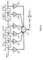
- Fig. 4 is a structural view of the filter.
- the filter includes delay elements 31-m to 31-(m-p), multipliers 32-0 to 32-p having filter coefficients C 0 to C p , respectively, and an adder 33.
- a high-pass filter is expressed by the expression below.
- the filter coefficients C k of the low-pass filter and high-pass filter given above are derived from the impulse response function.
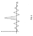
- Fig. 5 is a view showing the waveform of a conventional impulse response function.
- a SINC function shown in Fig. 5 has been applied as the conventional impulse response function, and the function value at the middle point of the distance between samples has been utilized as a filter coefficient C k .
- the SINC function is a function of infinite interval, and an infinite number of filter coefficients C k are required ideally.
- An actual filter must have a finite number of coefficients, but a very large number of coefficients are required to ensure certain precision in spite of an error caused by the reduction of coefficients.
- Fig. 6 is a view showing the waveform of an impulse response function according to the embodiment.
- This embodiment uses an impulse response function having a finite support as shown in Fig. 6 .
- Given below is an example of the function obtained by shifting the B-spline function at intervals of a half of the distance between sample points and performing synthesized approximation.
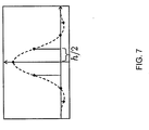
- Fig. 7 is an illustration of a discrete impulse response and filter coefficient value of the embodiment.
- a black dot in the figure indicates a sample point (singular point) in the impulse response function with finite support.
- ⁇ (t) is given as the waveform of impulse response having a finite support
- the filter coefficient (tap coefficient) C(k) with the filter delay time treated as a half of the sampling time width h
- a filter having this filter coefficient C(k) is called a basic low-pass filter L 0 .
- the basic low-pass filter is expressed as follows.
- the value of ⁇ (t) at connection points at intervals of h/2 in each section as shown in Fig. 7 is taken as the coefficient C(k), with the following settings being taken into account
- the basic low-pass filter L 0 (z) is expressed by the following equation.
- the frequency characteristics of the basic low-pass filter are expressed by the equation given below.
- Fig. 8 is a view showing an example of the frequency response of the low-pass filter of the embodiment. The figure shows the characteristics expressed by the equation given above.
- Fig. 9 is a structural view of the basic low-pass filter of the embodiment.
- An example of the arithmetic circuit of the basic low-pass filter L 0 is configured as shown in Fig. 9 .
- the basic low-pass filter includes delay elements 91-1, 91-2, 91-3, 91-4, 91-5, and 91-6, multipliers 92-1, 92-2, and 92-3, and adders 93-1, 93-2, 93-3, and 93-4.
- the filter coefficients of the multipliers 92-1, 92-2, and 92-3 are - 1/16, 9/16, and 1, respectively.
- the multiplier 92-3 can be omitted because the coefficient is 1.
- H 0 (z) Based on the low-pass filter L 0 (z), a basic high-pass filter H 0 (z) can be expressed by the following equation.
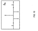
- Fig. 10 is an illustration of the discrete impulse response and filter coefficient value of the basic high-pass filter of the embodiment.
- the coefficient b(k) in the equation given above is obtained by inverting the sign of the coefficient C(k) alternately as shown in Fig. 10 .
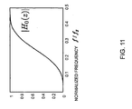
- Fig. 11 is a view showing an example of the frequency response of the basic high-pass filter of the embodiment.
- the high-pass filter H 0 (z) has frequency characteristics shown in Fig. 11 and can be expressed by the equation given below.
- the reason for using the impulse response functions such as the Fluency DA function is that the local support allows filter coefficients to be used in the range of finite numbers and that the even function (linear phase) can implement a linear phase.
- the maximally flat characteristics can solve a ripple problem in the passband.
- L M (z) and H M (z) are obtained by scaling L 0 (z) and H 0 (z), respectively by M + 1, where M is referred to as a scaling factor.
- a low-pass filter L M (z) and a high-pass filter H M (z) obtained by scaling the basic low-pass filter L 0 (z) and the basic high-pass filter H 0 (z) by M + 1 can be expressed respectively by the following equations.
- L M z L 0 ⁇ z M + 1
- H M z H 0 ⁇ z M + 1
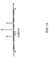
- Fig. 12 is an illustration of scaling by M in the embodiment. As the equations given above indicate, scaling in the frequency domain corresponds to upsampling in the time domain.
- the low-pass filter L M (z) and high-pass filter H M (z) are obtained by upsampling M times in the time domain as shown in Fig. 12 , which corresponds to insertion of M zeros between sample points.
- Fig. 13 is an illustration of scaled filters in the embodiment. Examples of the frequency characteristics of the low-pass filter L M (z) are shown in Fig. 13 .
- the figure shows the characteristics of filters L 1 and L 2 obtained by scaling the basic low-pass filter L 0 by 2 and 3, respectively.
- the basic filter L 0 is scaled to the filter L 1 as shown in the figure, and the filter L 1 is scaled to the filter L 2 as shown in the figure.
- a filter L 3 and subsequent filters are obtained likewise by scaling.
- FIG. 2 is a structural view of a scaled element filter in the embodiment.
- the figure shows a filter formed by scaling the basic filter by p + 1.
- the basic low-pass filter has delay elements 21-1, 21-2, 21-3, 21-4, 21-5, and 21-6 that cause a delay of p + 1 samples, multipliers 22-1, 22-2, and 22-3, and adders 23-1, 23-2, 23-3, and 23-4.
- the filter coefficients of the multipliers 22-1, 22-2, and 22-3 are -1/16, 9/16, and 1, respectively.
- the multiplier 22-3 can be omitted because the coefficient is 1.
- This filter has an arithmetic circuit implementing the following equation.
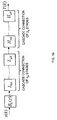
- Fig. 1 is a structural view of an example filter having a cascade connection of low-pass filters to implement the embodiment.
- the filter has n low-pass filters L pk (z) connected in cascade.
- the low-pass filter L pk (z) is an element filter formed by scaling the basic low-pass filter L 0 (z). Scaling is to define a filter by multiplying the basic filter by pk + 1 in the frequency domain or time domain.
- the shown configuration includes just scaled filters based on the low-pass filter. However, a configuration that includes high-pass filters alone or both high-pass filters and low-pass filters, which will be described later, is within the scope of this embodiment.
- Fig. 14 is an illustration of variations in frequency characteristics caused by cascade connections of the basic filters.
- scaled low-pass filters L pk (z) By connecting scaled low-pass filters L pk (z) in cascade as shown in Fig. 1 , filters having the frequency characteristics shown in Fig. 14 , for example, can be implemented.
- the cascade connection of scaled filters makes it possible to narrow the passband width and to lower the stopband sufficiently and creates other new characteristics.
- the filter of a single stage is the basic filter L 0 ; the filter of two stages includes the basic filter L 0 and the filter L 1 connected in cascade; the filter of three stages includes the basic filter L 0 , the filter L 1 , and the filter L 2 connected in cascade.
- the cascade connection of scaled filters can narrow the passband width and can also lower the stopband.
- the examples described above include just low-pass filters, but generally, a variety of filters X(z) can be configured by combining low-pass filters and high-pass filters.
- the filter X(z) can be expressed generally by the equation below.
- L p z L 0 ⁇ z p + 1
- H q z H 0 ⁇ z q + 1
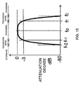
- Fig. 15 is an illustration of a band-pass filter of the embodiment.
- the figure shows the characteristics of the filter to be implemented as a design target.
- the requirements of the filter to be implemented include the following items.
- the corresponding symbols are shown in Fig. 15 .
- the sampling frequency fs is the repetition frequency of the signal input to the filter
- the center frequency fc is the frequency at the center of the filter, extracted from the frequency components included in the signal.
- fc/fs ⁇ 0.5, according to the Nyquist theorem.
- the cutoff frequency f 1 is the highest frequency at which the signal passes.
- the symmetrical frequency f -1 about the center frequency fc is the lowest frequency at which the signal passes.
- the attenuation of the passing signal at the cutoff frequencies f 1 and f -1 is -3 dB, in comparison with the original signal. An appropriate value other than -3 dB can be specified as the reference value.
- the attenuation A is defined with the magnitude X of the input signal and the magnitude Y of the filter output signal at the cutoff frequency, as indicated in the equation given below.
- the input signal is attenuated to about 70.8% (1/ ⁇ 2) at the cutoff frequencies f 1 and f -1 , and the result is output. This means that the amplitude energy of the signal is attenuated to a half.
- the signal passband is the range between the cutoff frequencies f 1 and f -1 , and the frequency width ⁇ fb(m) thereof is given by the following equation.
- ⁇ fb(m) is the passband of the filter formed by scaling by m + 1.
- the stopband frequencies f 2 and f -2 indicate that the frequency components above f 2 or below f -2 of the input signal are cut off.
- the transition band attenuation characteristics from the attenuation level (such as -3 dB) at the cutoff frequencies f 1 and f -1 to the attenuation degree Ad will be given.
- An appropriate value other than -80 dB can be specified as the reference value.
- the cutoff frequency should be equal to the stopband frequency. Since that is difficult to realize in actual filters, a transition band is provided.
- Y X 10 - 80 / 20 ⁇ 1 / 10000
- Fig. 16 is an illustration of a frequency shift of a band-pass filter in the embodiment.
- B B ⁇ B ⁇ ⁇ - ⁇ c + B ⁇ ⁇ + ⁇ c
- the frequency shift theorem gives the following.
- the filter B (z) is converted by multiplying the coefficient of the filter B(z) by 2cos( ⁇ c k). This means that when the filter B(z) is designed, the requirements should be converted as given below.
- Fig. 21 is an illustration of the band-pass filter of the embodiment. The figure shows the characteristics of the target filter to be implemented.
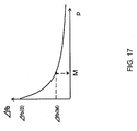
- Fig. 17 is an illustration of the relationship between the passband frequency width and scaling factor in this embodiment.
- the maximum scaling value M is determined by a required passband frequency width ⁇ fb.
- the passband width ⁇ fb narrows with an increase in scaling value, as clearly indicated in Fig. 13 , and the relationship between ⁇ fb and the scaling value p (or q) is as shown in Fig. 17 .
- the attenuation degree is calculated in decibels (dB) as follows.
- the ⁇ fb-p relationship satisfies the following.
- a low-pass filter L M (z) or a high-pass filter H M (z), where p, q M, is used as an initial value, for example. Then, p or q is selected in descending order, for example; an optimum combination of p, q, ⁇ p , and ⁇ q is selected; and B(z) is designed.
- Lp(z) or Hp(z) is selected in accordance with whether the attenuation degree at the stopband frequency fb is equal to or smaller than the required value Ad (such as -80 dB).
- Ad such as -80 dB
- a filter with the attenuation degree required at the cutoff frequency fa much lower than the value (-3 dB, for example) will not be selected.
- the filter B B (z) to be selected according to the criteria given above is expressed as follows.
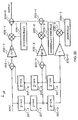
- Fig. 19 is a view showing an example configuration of the band-pass filter according to the embodiment.
- the band-pass filter is designed in the method described above in accordance with the configuration shown in the figure.
- the filter includes a filter B 0 (z) having the maximum scaling value, a filter containing low-pass filters L 0B to L pB formed by scaling by 0B to p B , respectively, connected in ⁇ p stages in cascade, and a filter containing high-pass filters H 0B to H qB formed by scaling by 0B to q B , respectively, connected in ⁇ q stages.
- Fig. 20 is a structural view of a low-pass filter L pB (z) formed by scaling by p + 1.
- the low-pass filter includes delay elements 201-1, 201-2, 201-3, 201-4, 201-5, and 201-6, which cause a delay of p + 1 samples, multipliers 202-1, 202-2, and 202-3, and adders 203-1, 203-2, and 203-3, and multipliers 205-1, 205-2, and 205-3.
- the filter coefficients of the multipliers 202-1, 202-2, and 202-3 are -1/16, 9/16, and 1, respectively.
- the coefficients of the multipliers 205-1, 205-2, 205-3 are 2(1 + cos(6 ⁇ c )), 2(cos(2 ⁇ c ) + cos(4 ⁇ c )), and 2cos(3 ⁇ c ), respectively.
- the multiplier 202-3 can be omitted because the coefficient is 1. Pairs of multipliers 202-1 and 205-1, multipliers 202-2 and 205-2, multipliers 203-3 and 205-3 can be configured as integrated multipliers.
- Fig. 26 is a structural view of a high-pass filter H qB (z) formed by scaling by q + 1.
- the high-pass filter includes delay elements 201-1, 201-2, 201-3, 201-4, 201-5, and 201-6, which cause a delay of q + 1 samples, multipliers 202-1, 202-2, and 202-3, adders 203-1, 203-2, and 203-3, and multipliers 205-1, 205-2, and 205-3.
- the filter coefficients of the multipliers 202-1, 202-2, and 202-3 are 1/16, -9/16, and 1, respectively.
- the coefficients of the multipliers 205-1, 205-2, and 205-3 are 2 (1 + cos(6 ⁇ c )), 2(cos(2 ⁇ c ) + cos(4 ⁇ c )), and 2cos(3 ⁇ c ), respectively.
- the multiplier 202-3 can be omitted because the coefficient is 1. Pairs of multipliers 202-1 and 205-1, multipliers 202-2 and 205-2, multipliers 203-3 and 205-3 can be configured as integrated multipliers.
- Fig. 22 is a structural view of the basic low-pass filter L 0B (z).
- the basic low-pass filter L 0B (z) expressed by the equation given above has the shown circuit configuration.
- the basic low-pass filter includes delay elements 21-1, 21-2, 21-3, 21-4, 21-5, and 21-6, which cause a delay of a single sample, multipliers 22-1, 22-2, 22-3, 22-4, and 22-5, and adders 23-1, 23-2, 23-3, and 23-4.
- the filter coefficients of the multipliers 22-1, 22-2, 22-3, 22-4, and 22-5 are -1/8, 9cos(2 ⁇ c )/8, 2cos(3 ⁇ c ), 9cos(4 ⁇ c )/8, and - cos(6 ⁇ c )/8, respectively.
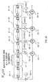
- Fig. 23 is a structural view of the low-pass filter L pB (z) formed by scaling by p + 1.
- the low-pass filter L pB (z) formed by scaling by p + 1 has the same structure as L OB , but z -1 is replaced with Z -(p+1) .
- the low-pass filter formed by scaling by p + 1 includes blocks 31-1, 31-2, 31-3, 31-4, 31-5, and 31-6 having p + 1 delay elements, multipliers 32-1, 32-2, 32-3; 32-4, and 32-5, and adders 33-1, 33-2, 33-3, and 33-4.
- the filter coefficients of the multipliers 32-1, 32-2, 32-3, 32-4, and 32-5 are -1/8, 9cos(2 ⁇ c )/8, 2cos(3 ⁇ c ), 9cos(4 ⁇ c )/8, and - cos(6 ⁇ c )/8, respectively.
- the delay elements 31-1 to 31-6 each have p + 1 delay elements.
- Each delay element block may have any number of delay elements, if they cause a delay of p + 1 samples.
- Fig. 24 is a structural view of the basic high-pass filter H 0B (z).
- the basic high-pass filter H 0B (z) has the shown circuit configuration.
- the basic high-pass filter has delay elements 41-1, 41-2, 41-3, 41-4, 41-5, and 41-6 that cause a delay of a single sample, multipliers 42-1, 42-2, 42-3, 42-4, and 42-5, and adders 43-1, 43-2, 43-3, and 43-4.
- the filter coefficients of the multipliers 42-1, 42-2, 42-3, 42-4, and 42-5 are 1/8, -9cos(2 ⁇ c )/8, 2cos(3 ⁇ c ), -9cos(4 ⁇ c )/8, and cos(6 ⁇ c )/8, respectively.
- Fig. 25 is a structural view of the high-pass filter H qB (z) formed by scaling by q + 1.
- the high-pass filter H qB (z) formed by scaling by q + 1 has the same structure as the filter H 0 as shown in the figure, but Z -1 is replaced with Z -(q+1) .
- the high-pass filter formed by scaling by q + 1 includes blocks 51-1, 51-2, 51-3, 51-4, 51-5, and 51-6 that have q + 1 delay elements, multipliers 52-1, 52-2, 52-3, 52-4, and 52-5, and adders 53-1, 53-2, 53-3, and 53-4.
- the filter coefficients of the multipliers 52-1, 52-2, 52-3, 52-4, and 52-5 are 1/8, -9cos(2 ⁇ c )/8, 2cos(3 ⁇ c ), -9cos(4ro c )/8, and cos(6 ⁇ c )/8, respectively.
- the delay elements 51-1 to 51-6 each have q + 1 delay elements.
- Each delay element block may have any number of delay elements, if they cause a delay of q + 1 samples.
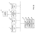
- Fig. 32 is a structural view of the hardware of a design system according to the embodiment.
- the design system includes a processing unit 1, which is a central processing unit (CPU), an input unit 2, an output interface unit 3, a display unit 4, a storage unit 5, and a filter circuit 6.
- the processing unit 1, input unit 2, output interface unit 3, display unit 4, and storage unit 5 are connected by a star, bus, or another connection means.
- the processing unit 1 accesses the storage unit 5 and executes filter design processing.
- the storage unit 5 includes a filter configuration file 51 that stores design specifications and requirements (such as conditions (range, value, ratio, etc) of the passband and stopband, upper limits of the numbers ⁇ p and ⁇ q of filters connected in cascade), a basic filter characteristics file 52 that stores the characteristics of the basic low-pass filter, the low-pass filters L 0 to L p formed by scaling the basic low-pass filter, the low-pass filter L pB formed by multiplying the filter coefficient of the filter L p by 2cos( ⁇ c k), the basic high-pass filter, the high-pass filters H 0 to H q formed by scaling the basic high-pass filter, and the high-pass filter H qB formed by multiplying the filter coefficients of filter Hq by 2cos( ⁇ c k), and a filter output file 53 that stores data and parameters (such as the shift amount B, maximum scaling value M, filter coefficients p, q, ⁇ p , ⁇ q of multipliers) for determining a designed filter configuration and intermediate results
- the processing unit 1 can output these data items (for example, data and parameters for determining the filter configuration, such as the filter coefficients of multipliers) through the output interface unit 3 to the filter circuit 6.
- the filter circuit 6 is provided by software or hardware and implements a filter having the specified characteristics in accordance with the data items set up through the output interface unit 3 by the processing unit 1.
- Fig. 18 is a flowchart illustrating a processing procedure in the embodiment.
- the design system configures a filter through steps S01 to S07 described below.
- the processing unit 1 specifies beforehand desired characteristics data to be given as design specifications and requirements, including the center frequency fc, cutoff frequency f1, stopband frequency f2, passband attenuation degree A, stopband attenuation degree Ad, and sampling frequency fs, for example, by storing them in the storage unit 5 (filter configuration file 51) through operations from the input unit 2 or by reading the values stored in the storage unit 5 (filter configuration file 51) beforehand.
- the processing unit 1 reads the values of characteristics data specified in step S01, from the storage unit 5 (filter configuration file 51), and calculates the shift amount B, which shifts the center frequency fc to the origin O, by the equation given below, in accordance with the input characteristics data.
- B [fc/fs] (The square brackets indicate that fractions are rounded off to the whole numbers.)
- the processing unit 1 stores the obtained shift amount B in the storage unit 5 (filter output file 53).
- the processing unit 1 also converts the center frequency fc, cutoff frequency f1, and stopband frequency f2 of the input characteristics data to the center frequency 0, cutoff frequency f a , and stopband frequency f b , respectively, in accordance with the shift amount B, and stores the values in the storage unit 5 (filter output file 53).
- the processing unit 1 reads the values of the characteristics data specified in step S01, from the storage unit 5 (filter configuration file 51), and calculates the scaling value (scaling factor) M of the highest degree on the basis of the input characteristics data. To obtain the scaling value M of the highest-degree (maximum scaling value), the processing unit calculates the passband width ⁇ fb(M) of the filter formed by scaling by M + 1, as given below, for example.
- Passband width ⁇ fb M f ⁇ 1 - fc * 2
- the processing unit 1 obtains the maximum scaling value M from the passband width ⁇ fb(M) by referencing a scaling curve stored in advance in the storage unit 5 (basic filter characteristics file 52) or by calculating the equation of a scaling curve.
- the processing unit 1 reads from the storage unit 5 (filter configuration file 51 and filter output file 53) the values specified in step S01 and the maximum scaling value M calculated in step S03.
- the processing unit 1 also selects from the storage unit 5 an optimum combination of p, q, ⁇ p , and ⁇ q in accordance with the filter combination as given by the equation below.
- the processing unit 1 reads from the storage unit 5 (basic filter characteristics file 52) the characteristics of the low-pass filter L p and high-pass filter Hq determined by p and q, calculates the characteristics of B(z) on the basis of the equation given above, and selects values conforming to the passband and stopband design specifications on a round-robin basis.
- the processing unit 1 may further select values that minimize the number of multipliers.
- the selection of L p (z) and Hp(z) is made, depending on whether the attenuation degree at the stopband frequency fb is lower than or equal to the required value Ad (for example, -80 dB), and, at the same time, depending on it that a filter with an attenuation degree much lower than the required value (for example, -3 dB) at the cutoff frequency fa will not be selected (for example, a filter below a predetermined permissible level will not be selected).
- Ad for example, -80 dB
- the maximum values of ⁇ p and ⁇ q can be specified beforehand in the storage unit 5 (filter configuration file 51) or the like, and the processing unit 1 can select an optimum combination of p, q, ⁇ p , and ⁇ q by selecting ⁇ p and ⁇ q in descending order from the stored maximum values and selecting p and q in descending order from the maximum scaling value M.
- the processing unit may make the following judgment or processing.
- the characteristics of filters formed by scaling the basic low-pass filter and basic high-pass filter are stored beforehand in the storage unit 5 (basic filter characteristics file 52). However, the characteristics of just the basic low-pass filter and the basic high-pass filter may be stored in the basic filter characteristics file 52, and the processing unit 1 may obtain the characteristics of a desired scaled filter through scaling based on the stored characteristics as necessary and use those characteristics. The processing unit 1 stores the obtained p, q, ⁇ p , and ⁇ q in the storage unit 5 (filter output file 53).
- the processing unit 1 reads from the storage unit 5 (filter output file 53) the specification data and parameters for configuring the filter, such as p, q, ⁇ p , and ⁇ q , reads further from the storage unit 5 (basic filter characteristics file 52) the characteristics of the filter L 0M or filter H 0M corresponding to B 0 (z), according to the low-pass filter or the high-pass filter, and the characteristics of the filter L pB and filter H qB , forms the filter B B (z) in accordance with the equation given below, and displays on the display unit 4 the filter characteristics and the parameters and data that are used or stores them in the storage unit 5 (filter output file 53), or both displays and stores them.
- filter output file 53 the specification data and parameters for configuring the filter
- the processing unit 1 can also read from the storage unit 5 (filter output file 53) the specification data and parameters for configuring the filter, such as p, q, ⁇ p , and ⁇ q , read from the storage unit 5 (basic filter characteristics file 52) the characteristics of the filters L pB and H qB , and output the values through the output interface unit 3 to the filter circuit 6.
- the processing unit 1 may use the filter circuit 6 to form the filter B B (z) in accordance with the read values.
- the filter circuit 6 can form the filter B B (z) with a computer simulation or by software.
- the filter circuit 6 may be configured by hardware to form the filter B B (z) in accordance with the values output from the output interface unit 3.
- the impulse response can be calculated by a simulation program such as the well-known MATLAB to obtain the waveform of the impulse response.
- an expansion of X(z) given above can be derived by a mathematical operation program such as the well-known MATHEMATHICA.
- the expansion is the impulse response function of X(z).
- Fig. 27 shows a filter structural diagram.
- the filter includes multipliers 72-0 to 72-k, delay elements 71-1 to 71-k that cause a delay of a single sample, and adders 73-1 to 73-k.
- the processing unit 1 reads data (filter coefficients, p, q, ⁇ p , ⁇ q , etc.) for configuring the filter from the storage unit 5 (filter output file 53), obtains the impulse response by using the filter circuit 6 or the like, and stores the coefficient C k of the impulse response in the storage unit 5 (filter output file 53).
- the processing unit 1 reads the filter coefficient from the storage unit 5 and uses the filter circuit 6, the coefficients C k (k + 1 coefficients) can be used as the filter coefficients (tap coefficients) in the shown circuit configuration, and the filter can be configured by using k delay elements z -1 .
- Fig. 28 shows another filter structural diagram.
- the filter includes multipliers 82-0 to 82-M, delay elements 81-1 to 81-M, and an adder 83.
- a filter having characteristics designed in accordance with the filter coefficient C k obtained as described above can be configured as shown in the figure besides the filter configuration described earlier.
- Fig. 29 is a frequency characteristics diagram of filters designed with theoretical values by different methods. As the left graph shows, the Remez method satisfies the requirements but generates ripples in the passband and stopband. The right graph shows that the filter according to the present invention satisfies the specifications and makes a large attenuation in the stopband.
- Fig. 30 is a frequency characteristics diagram of filters designed by the methods after coefficient quantization.
- the left graph clearly shows that the Remez method produces errors throughout the stopband.
- the right graph shows that the filter according to the present invention produces just a few errors in the transition band.
- Fig. 31 shows the characteristics of the filter according to the present invention, evaluated against the requirements. As shown in the figure, the filter according to the present invention can be implemented with a much smaller number of taps in comparison with the conventional method.
- a filter configuration (design) method or filter configuration (design) apparatus or system according to the present invention can be provided by a filter configuration (design) program for executing each procedure on a computer, a computer-readable recording medium having the filter configuration (design) program recorded on it, a program product that includes the filter configuration (design) program and can be loaded into the internal memory of the computer, a server or any other computer that includes the program, and the like.
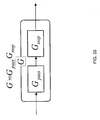
- Fig. 33 is a circuit diagram of a filter G.
- Fig. 34 is a circuit diagram of G pass .
- Figs. 35 and 36 are expanded views of G pass .
- Figs. 35 shows a part related to a first term of G pass .
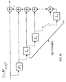
- Fig. 36 shows a part related a second term of G pass .
- L m and H m described above, the filter passband main part G pass is formed as indicated below.
- G pass is expressed by the equation given below.
- G pass L P , N P 1 ⁇ P ⁇ 1 - H P , N P 2 ⁇ P . where the superscripts and subscripts of G pass indicate the following:
- Fig. 37 is a circuit diagram of G stop .
- the stopband main part G stop is also formed as indicated below.
- S top is expressed by the equation given below.
- Fig. 38 is a structural view of hardware related to the embodiment.
- the hardware includes a processing unit 1, which is a central processing unit (CPU), an input unit 2, an output interface unit 3, a display unit 4, a storage unit 5, and a filter circuit 6.
- the processing unit 1, input unit 2, output interface unit 3, display unit 4, and storage unit 5 are connected by a star, bus, or another connection means.
- the storage unit 5 includes a filter configuration file 51 that stores design specifications and requirements (such as conditions (range, value, ratio, etc) of the passband and stopband, the upper limit N pass of the number of multipliers, etc.), a basic filter characteristics file 52 that stores the characteristics of the basic low-pass filter, the scaled low-pass filters (L 0 , L 1 , ...
- the filter output file 53 that stores data and parameters (such as the filter coefficients N pass , N p (1) , N p (2) ⁇ p , ⁇ p , P, N k , N l , ⁇ pk , ⁇ pl , p k , q l of multipliers, etc.) for determining a designed filter configuration, and intermediate results, final results, and so on by the processing unit 1, such as the designed filter characteristics.
- data and parameters such as the filter coefficients N pass , N p (1) , N p (2) ⁇ p , ⁇ p , P, N k , N l , ⁇ pk , ⁇ pl , p k , q l of multipliers, etc.
- the processing unit 1 can output these data items (for example, data and parameters for determining the filter configuration, such as the filter coefficients of multipliers) through the output interface unit 3 to the filter circuit 6.
- the filter circuit 6 is configured by software or hardware and implements a filter having the specified characteristics in accordance with the data items set up through the output interface unit 3 by the processing unit 1.
- Fig. 39 is a flowchart of a filter design procedure (low-pass filter). This flowchart includes the following steps:
- Input design specifications (S0)
- the processing unit 1 specifies beforehand design specifications (conditions (range, value, ratio, etc) of the passband and stopband, the upper limit N pass of the number of multipliers, etc.) by storing them in the storage unit 5 (filter configuration file 51) through operations from the input unit 2 or by reading the values stored in the storage unit 5 (filter configuration file 51) beforehand.
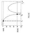
- Fig. 40 is a graph showing the cutoff characteristics of a cascade connection model G(f) of a product-sum module.
- f 3 and f 80 indicate the following:
- Step S1. (Determine the maximum value of p)
- the processing unit 1 may allow the P value to be predetermined by the input unit 2 or storage unit 5 (filter output file 53).
- the processing unit 1 regards f 3 (p) as the -3 dB point of L p , calculates f 3 (0) in advance, and specifies the minimum value of p that satisfies the following as P.
- f 3 p f 3 0 1 + p ⁇ f 3
- the processing unit 1 stores the obtained value of P in the storage unit 5 (filter output file 53).
- Step S2 Configure the passband main part
- the processing unit 1 reads the characteristics of the low-pass filter and high-pass filter determined by N p (1) , N p (2) , ⁇ p , ⁇ p , from the storage unit 5 (basic filter characteristics file 52), calculates the characteristics of G pass by the equation given above, and selects the set that satisfies the design specifications (R ⁇ R 0 , for example) and minimizes the number of multipliers on a round-robin basis.
- the processing unit 1 may select a set that also conforms to the design specifications of the passband and stopband. However, the following rules of combination are defined.
- the processing unit 1 stores the obtained N p (1) , N p (2) , ⁇ p , ⁇ p in the storage unit 5 (filter output file 53).
- the processing unit 1 may select a set that also conforms to the design specifications of the passband and stopband.
- the processing unit 1 stores the obtained N k , N l , ⁇ pk , ⁇ ql in the storage unit 5 (filter output file 53).
- Step S4. Configure and output G
- the storage unit 5 filter output file 53
- the filter circuit 6 can form the filter G with a computer simulation or by software.
- the filter circuit 6 may also form the filter G by hardware, in accordance with the values output from the output interface unit 3.
- the characteristics of filters formed by scaling the basic low-pass filter and the basic high-pass filter are stored in advance in the storage unit 5 (basic filter characteristics file 52).
- the characteristics of just the basic low-pass filter and the basic high-pass filter may be stored in the basic filter characteristics file 52, and the processing unit 1 may perform scaling based on the stored characteristics as needed to obtain and use the characteristics of a designated scaled filter.
- Fig. 45 is an illustration of an example (low-pass filter) in which the characteristics are improved by G(f).
- the figure shows the characteristics of the filter G obtained by forming the filter G(f) given by the equation below, by connecting the low-pass filters L 0 (f) and L 1 (f) in cascade.
- G f L 0 f ⁇ L 1 f
- the characteristics can be made steeper by connecting element filters in cascade.
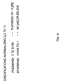
- Fig. 41 is an illustration of the specifications of a low-pass filter.
- An example configuration of the low-pass filter will now be given in accordance with the configuration means described above.
- the desired characteristics specifications are as shown in the figure.
- the passband and stopband are ranges of normalized frequency.
- the configuration of the filter designed in accordance with the flowchart in this embodiment is expressed as follows.
- G L 3 7.9 ⁇ L 1 3.1 ⁇ L 1 4.2 ⁇ L 1 5.3 ⁇ 1 - H 1 1.1 ⁇ 1 - H 1 2.1
- G pass L 3 7.9 is specified.
- Fig. 42 is an illustration of G pass and G stop of the filter G.
- the characteristics diagram of G pass is shown in Fig. 42 (a) .
- the stopband the second to fourth side lobes of G pass must be blocked.
- the third and fourth side lobes are generally blocked by (1 - H 1 1.1 ) and (1 - H 1 2.1 ) in Fig. 26(b) .
- P ⁇ 5 is taken, and, as shown in Fig.
- Fig. 43 is a characteristics diagram of filters configured by conventional methods and the present invention.
- the least squares method is shown at (a); the Remez method is shown at (b); and the method of the present invention is shown at (c).
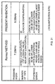
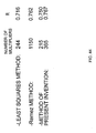
- Fig. 44 is a chart comparing the number of multipliers and R of the design methods.
- the number of multipliers here was obtained when the characteristics satisfied all the specifications for the first time.
- the method of the present invention is superior to the least squares method in terms of both the number of multipliers and R.
- the Remez method is slightly better than the method according to the present invention in R, but the number of multipliers is as large as 1142.
- an m-th-degree piecewise polynomial can be used, for example.
- An interpolation function with waveform adjustment parameters or the like can also be used.
- the present invention can be applied to a variety of technologies such as acoustic technologies, video technologies, image technologies, transmission technologies, communication technologies, analog-to-digital conversion and digital-to-analog conversion technologies, compression and decompression technologies, encryption and decryption (decompression) technologies, and filter technologies.
- the present invention can be used in acoustic, image, communication, and other signal processing filters in wide areas.
- the present invention can be used in wide range of apparatuses such as acoustic equipment that includes amplifiers, image apparatuses for moving or still picture processing, communication devices such as mobile phones, controllers, computers, and PCs.
Landscapes
- Engineering & Computer Science (AREA)
- Physics & Mathematics (AREA)
- Computer Hardware Design (AREA)
- Mathematical Physics (AREA)
- Computing Systems (AREA)
- Theoretical Computer Science (AREA)
- Tone Control, Compression And Expansion, Limiting Amplitude (AREA)
- Filters And Equalizers (AREA)
- Compression, Expansion, Code Conversion, And Decoders (AREA)
- Filters That Use Time-Delay Elements (AREA)
Abstract
Description
- The present invention relates to filters, and more specifically, to a finite impulse response (FIR) filter having a small number of taps and steep attenuation characteristics.
- With recent digitalization of multimedia information, the importance of arithmetic processing algorithms and arithmetic processing circuits that implement digital signal processing has been increasing. Especially, digital filters are used to eliminate noise, adjust frequency characteristics, separate signals, and so on. FIR filters having finite impulse response ensure stability always against bounded input. If the impulse response is symmetrical, the FIR filters can implement perfect linear phases. The linear phases are important characteristics in waveform transmission, measurement, sound reproduction, and so on. However, because of the trade-off between precision required in the frequency characteristics of the filter and the scale of the filter, high-order transfer characteristics are required to obtain steeper attenuation characteristics, and the circuit requires a large number of multipliers and delay elements. To create a pass-band filter with a very narrow band, for example, a very high degree of transfer characteristics is required, and a large number of multipliers are required accordingly.
- In that context, many propositions have been made.
Non-patent literature 1 describes the Remez method as a conventional method that has been used usually.Non-patent literature 2 describes a method of configuring a low-sensitivity linear-phase FIR filter by cascade connection, and the cascade connection allows the number of multipliers to be reduced.Patent literature 1 describes an FIR filter provided to vary the delay of the filter output signal.
Moreover, FIR filters for various uses such as filters for separating acoustic signal bands and filters for eliminating noise in image have been studied. - There are more conventional technologies. For example, non-patent
literature 3 discloses the design and implementation of oversampled filter banks for multilevel FIR filters with low aliasing.
Non-patentliterature 4 discloses a filter bank with desired frequency response and low aliasing noise.
Non-patent literature 5 discloses a realization of oversampled cosine modulated filter banks with perfect reconstruction.
Patent literature 2 discloses a filter bank and filtering method that can efficiently implement critically sampled filter banks for real-value signals and especially a cosine modulated filter bank. -
- Non-patent literature 1: D. Shpak, "A generalized Remez method for the design of FIR digital filters, " IEEE Trans. Circuit System, Vol. 37, No. 2, pp. 161-174, Feb. 1990.
- Non-patent literature 2: Hitoshi Honma, Yukio Mori, Masahiko Sagawa, "Low-Sensitivity Realization of Linear-Phase FIR Digital Filters Using Cascade Form," IEICE Trans., Vol. J70-A, No. 5, pp. 766-774, May 1987.
- Non-patent literature 3: Kouno, Takazawa, et al., "Design and Implementation of Oversampled Filter Banks for Multilevel FIR Filters with Low Aliasing," 229th workshop (June 9, 2006), Tohoku Chapter, the Society of Instrument and Control Engineers, Document No. 229-8, pp. 1-11
- Non-patent literature 4: Takazawa, Abe, et al., "Design of a Filter Bank with Desired Frequency Response and Low Aliasing Noise," 215th workshop (May 27, 2004), Tohoku Chapter, the Society of Instrument and Control Engineers, Document No. 215-7, pp. 1-10
- Non-patent literature 5: Itami, Watanabe, et al, "A Realization of Oversampled Cosine Modulated Filter Banks with Perfect Reconstruction," IEICE Trans. A, Vol. J83-A No. 9, pp. 1037-1046, September 2000
-
- Patent literature 1: Japanese Unexamined Patent Application Publication No.
2006-20191 - Patent literature 2: Japanese Unexamined Patent Application Publication No.
2001-102931 - In any conventional filter, however, the number of multipliers (number of multiplications in calculation by software) and the number of delay elements (number of memories in processing by software) have not been reduced dramatically.
For example, according tonon-patent literature 1, extensive numbers of multipliers and delay elements are required to implement a filter having steep attenuation characteristics. According tonon-patent literature 2, low-sensitivity filters can be realized, but the technology is not suitable for filters having steep attenuation characteristics. - A high-performance filter having steep attenuation characteristics configured by any conventional method requires extensive numbers of input taps, delay circuits, and multipliers, and it has taken very long until filter output with predetermined characteristics becomes stable.
Music, video, and other multimedia data distributed recently in MP3 (audio compression), MPEG (video compression), and other forms involves problems such as the deluge of information and quality lowered by jaggies. The compression processing includes band separation in the frequency domain, which requires excessive numbers of multipliers and delay elements. - Since the conventional REMEZ filter uses the SINC function (function over the infinite interval) as the basic function, reduction to a finite interval is needed in the actual circuit and is known as one possible cause of noise.
In view of the problems described above, it is an object of the present invention to provide a filter that can exhibit designated characteristics with reduced numbers of input taps, delay circuits, and multipliers, can improve the response, and can lower the cost. - Another object of the present invention is to provide a low-cost FIR filter with high noise elimination characteristics.
A further object of the present invention is to provide an FIR filter that does not generate jaggies and is suitable for signal processing.
FIR filters can be used in a variety of apparatuses such as audio apparatuses including amplifiers, image apparatuses for moving or still image processing, communication apparatuses including mobile phones, control apparatuses, PCs and other computers. - Since one main feature of the present invention is that the basic function is an impulse response function expressed by an n-th-degree piecewise polynomial having a finite support, and nodal values of the function are used as filter coefficients, a filter configured according to the present invention samples the input signal at a smaller number of points, in comparison with a filter using the conventional SINC function as the basic function, and can exhibit frequency characteristics without support reduction error or aliasing error.
Another feature of the present invention is that the n-th-degree piecewise polynomial needs to be a quadratic to quartic function, and the frequency characteristics in the passband are flat with reduced ripples and have linear phases. - Another feature of the present invention is that scaling the basic filters in frequency allows the passband to be narrowed in accordance with the scaling value and increases the number of zero points, consequently increasing the attenuation degree in the stopband.
A further feature of the present invention is the cascade connection of scaled filters, which allows a high-performance filter to be configured with a reduced number of multipliers.
An additional feature of the present invention is that the cascade connection of the scaled filters means the combination of low-pass and high-pass scaled filters having a desired passband or a wider passband and ensures desired cutoff frequencies.
A further additional feature of the present invention is that since scaled filters are selected depending on the attenuation degree in the stopband, a very high attenuation degree can be provided in the stopband. - According to a first solving means of the present invention, a filter providing desired characteristics is provided by combining
a basic low-pass filter or a basic high-pass filter using a nodal value of an impulse response function configured by a piecewise polynomial with a finite support as a filter coefficient; and
a plurality of scaled filters formed by scaling the basic filter in the time domain or the frequency domain. - According to a second solving means of the present invention, a filter formed like a filter B(z) expressed by the equation given below is provided by connecting low-pass filters Lp and high-pass filters Hq in cascade as indicated by the equation given below, the filters Lp being formed by scaling a basic low-pass filter which uses nodal values of the impulse response function configured by a piecewise polynomial with a finite support as filter coefficients, by p + 1 (p being an integer larger than or equal to zero, and p being 0 for the basic filter) in the time domain or frequency domain, the filters Hq being formed by scaling a basic high-pass filter which uses the filter coefficients with their signs inverted alternately, by q + 1 (q being an integer larger than or equal to zero, and q being 0 for the basic filter) in the time domain or frequency domain.

- αp, βq: Exponential value (indicating that identical Lp or Hq is connected αp or βq times)
- P, Q: Maximum values of scaling values p and q
- According to a third solving means of the present invention, a filter is provided with a basic configuration in which signals delayed by multiplying discrete input in a finite interval by a coefficient are added sequentially and scaled filters formed by increasing or decreasing the number of delay elements in the basic configuration, the scaled filters being connected in cascade to output the signals.
- According to a fourth solving means of the present invention, an FIR filter providing desired characteristics is provided by combining
a basic low-pass filter or a basic high-pass filter using a nodal value of an impulse response function configured by a piecewise polynomial with a finite support as a filter coefficient; and
a plurality of scaled filters formed by scaling the basic filter in the time domain or the frequency domain;
wherein a center frequency, a cutoff frequency, a stopband frequency, the maximum attenuation degree in a stopband, and a sampling frequency are input;
the maximum scaling degree is determined from a passband frequency width determined by the cutoff frequency and the center frequency;
scaled filters having a degree lower than the maximum scaling degree are sequentially selected;
it is determined whether scaled filters selected to keep an attenuation degree at the stopband frequency of the FIR filter to be obtained lower than or equal to the maximum attenuation degree are employed; and
the FIR filter is configured by a cascade connection of the scaled filters. - According to a fifth solving means of the present invention, a filter is provided by connecting a passband filter Gpass and a stopband filter Gstop in cascade, the passband filter Gpass being formed by a cascade connection of a basic low-pass filter L0 using nodal values of a sampling function expressed by a finite piecewise polynomial as filter coefficients, a plurality of low-pass filters LM formed by scaling the basic low-pass filter in frequency, a basic high-pass filter H0 using the filter coefficients with their signs inverted alternately, and a plurality of high-pass filters HM formed by scaling the basic high-pass filter in frequency, as given by the equation below:

- αP, βP: Exponential value (indicating that identical LP,N1 or [1 - HP,N2] is connected αP or βP times. Here, N1 = Np (1) and N2 = Np (2) for the sake of convenience of description),
- NP (1) : Number of HP ladder connections in LP,N1,
- NP (2) : Number of LP ladder connections in [1 - HP,N2],
- P: Filter formed by scaling by P + 1 in frequency;
- the stopband filter Gstop being formed by a cascade connection of the basic low-pass filter L0, the low-pass filters LM, the basic high-ass filter H0, and the high-pass filters HM, as given by the equation below:

- αk, β1: Exponential value (indicating that identical Lpk,Nk or [1 - Hql,Nl] is connected αk or βl times),
- Nk : Number of Hp ladder connections in Lpk,Nk.
- Nl: Number of Lp ladder connections in [1 - Hql,Nl].
- pk, ql : Filters formed by scaling by pk + 1 and by ql + 1 in frequency.
- According to a sixth solving means of the present invention, a filter is provided on the basis of a low-pass filter and a high-pass filter which use nodal values of an impulse response function expressed by a piecewise polynomial with a finite support as coefficients, and the filter passband characteristics are formed by selecting scaled filters formed by scaling the low-pass filter and the high-pass filter in frequency to provide a passband width larger than or equal to a predetermined required width, by using the selected scaled filters to choose a scaled low-pass filter that satisfies required characteristics, and by connecting the scaled high-pass filters to the chosen scaled low-pass filter in a ladder manner.
- According to a seventh solving means of the present invention, a filter is provided on the basis of a low-pass filter and a high-pass filter which use nodal values of an impulse response function expressed by a piecewise polynomial with a finite support as coefficients, and the filter passband characteristics are formed by selecting scaled filters formed by scaling the low-pass filter and the high-pass filter in frequency to provide a passband width larger than or equal to a predetermined required width, by using the selected scaled filters to choose a scaled high-pass filter that satisfies required characteristics, and by connecting the scaled low-pass filters to the chosen scaled high-pass filter in a ladder manner.
- According to the present invention, low-pass filters, high-pass filters, and band-pass filters that have reduced numbers of taps, delay circuits, and multipliers and exhibit excellent frequency separation can be implemented because the filters are configured by scaled filters formed by scaling basic filters with steep attenuation characteristics. Since the attenuation degree in the stopband can be increased, a filter with a high noise reduction capability can also be implemented according to the present invention. Since the number of taps (multipliers) can be reduced greatly in comparison with conventional filters, a low-cost filter can be provided according to the present invention.
-
-
Fig. 1 is a structural view of a filter according to an embodiment. -
Fig. 2 is a structural view of a scaled element filter in the embodiment. -
Fig. 3 is a schematic illustration of filter processing in the embodiment. -
Fig. 4 is a structural view of a general filter in the embodiment. -
Fig. 5 is a view showing the waveform of a conventional impulse response function in the embodiment. -
Fig. 6 is a view showing the waveform of an impulse response function according to the embodiment. -
Fig. 7 is an illustration of a discrete impulse response and filter coefficient values in the embodiment. -
Fig. 8 is a view showing an example of the frequency response of a low-pass filter in the embodiment. -
Fig. 9 is a structural view of a basic low-pass filter in the embodiment. -
Fig. 10 is an illustration of the discrete impulse response and filter coefficient values of a basic high-pass filter in the embodiment. -
Fig. 11 is a view showing an example of the frequency response of the basic high-pass filter in the embodiment. -
Fig. 12 is an illustration of scaling by M in the embodiment. -
Fig. 13 is an illustration of a scaled filter in the embodiment. -
Fig. 14 is a view illustrating a cascade connection configuration and showing an example of its frequency response in the embodiment. -
Fig. 15 is an illustration of a band-pass filter in the embodiment. -
Fig. 16 is an illustration of a frequency shift of the band-pass filter in the embodiment. -
Fig. 17 is an illustration of the relationship between a passband frequency width and scaling factor in this embodiment. -
Fig. 18 is a flowchart illustrating a processing procedure in the embodiment. -
Fig. 19 is a view showing an example configuration of the band-pass filter according to the embodiment. -
Fig. 20 is a structural view of a scaling filter module of the band-pass filter in the embodiment. -
Fig. 21 is an illustration of the band-pass filter of the embodiment. -
Fig. 22 is a structural view of a basic low-pass filter L0B(z). -
Fig. 23 is a structural view of a low-pass filter LpB(z) formed by scaling by p + 1. -
Fig. 24 is a structural view of a basic high-pass filter H0B(z). -
Fig. 25 is a structural view of a high-pass filter HpB(z) formed by scaling by p + 1. -
Fig. 26 is a structural view of a high-pass filter HqB(z) formed by scaling by p + 1. -
Fig. 27 shows a filter structural view. -
Fig. 28 shows another filter structural view. -
Fig. 29 is a frequency characteristics diagram of a filter designed with theoretical values by each method. -
Fig. 30 is a frequency characteristics diagram of a filter designed by each method after coefficient quantization. -
Fig. 31 shows the evaluation of a filter according to the present invention in comparison with required specifications. -
Fig. 32 is a structural view of the hardware of a design system according to the embodiment. -
Fig. 33 is a circuit diagram of a filter G. -
Fig. 34 is a circuit diagram of Gpass. -
Fig. 35 is an expanded view of Gpass, related to a first term of Gpass. -
Fig. 36 is an expanded view of Gpass, related to a second term of Gpass. -
Fig. 37 is a circuit diagram of Gstop. -
Fig. 38 is a structural view of hardware related to the embodiment. -
Fig. 39 is a flowchart of a filter design procedure (low-pass filter). -
Fig. 40 is a view showing the cutoff characteristics by a cascade connection model G(f) of a product-sum module. -
Fig. 41 is an illustration of the specifications of a low-pass filter. -
Fig. 42 is an illustration of Gpass and Gstop of a filter G. -
Fig. 43 shows characteristics diagrams of filters configured by conventional methods and the present invention. The least squares method is shown at (a); the Remez method is shown at (b); and a method of the present invention is shown at (c). -
Fig. 44 is a view comparing the number of multipliers and R of the design methods. -
Fig. 45 is an illustration of an example (low-pass filter) in which the characteristics are improved by G(f). - To give a better understanding of the present invention, an embodiment will be described.
-
Fig. 3 is an outlined illustration of filter processing.
A non-recursive digital filter is also called a finite impulse response (FIR) filter since the impulse response is expressed by a finite number of pulses. - Generally, an FIR filter can be obtained from an input-output relationship as shown below, by multiplying the past and current input signals X(m) by a predetermined coefficient (filter coefficient) C(k), as shown in
Fig. 3 , where X(m) is an input signal and Y(m) is an output signal.

-
Fig. 4 is a structural view of the filter.
The filter includes delay elements 31-m to 31-(m-p), multipliers 32-0 to 32-p having filter coefficients C0 to Cp, respectively, and anadder 33.
A high-pass filter is expressed by the expression below.
The filter coefficients Ck of the low-pass filter and high-pass filter given above are derived from the impulse response function. -
Fig. 5 is a view showing the waveform of a conventional impulse response function.
A SINC function shown inFig. 5 has been applied as the conventional impulse response function, and the function value at the middle point of the distance between samples has been utilized as a filter coefficient Ck. The SINC function, however, is a function of infinite interval, and an infinite number of filter coefficients Ck are required ideally. An actual filter must have a finite number of coefficients, but a very large number of coefficients are required to ensure certain precision in spite of an error caused by the reduction of coefficients. -
Fig. 6 is a view showing the waveform of an impulse response function according to the embodiment.
This embodiment uses an impulse response function having a finite support as shown inFig. 6 . Given below is an example of the function obtained by shifting the B-spline function at intervals of a half of the distance between sample points and performing synthesized approximation.
- h:
- Sampling time interval
- f:
- Frequency
- According to Japanese Unexamined Patent Application Publication No.
2001-842442 
-
Fig. 7 is an illustration of a discrete impulse response and filter coefficient value of the embodiment.
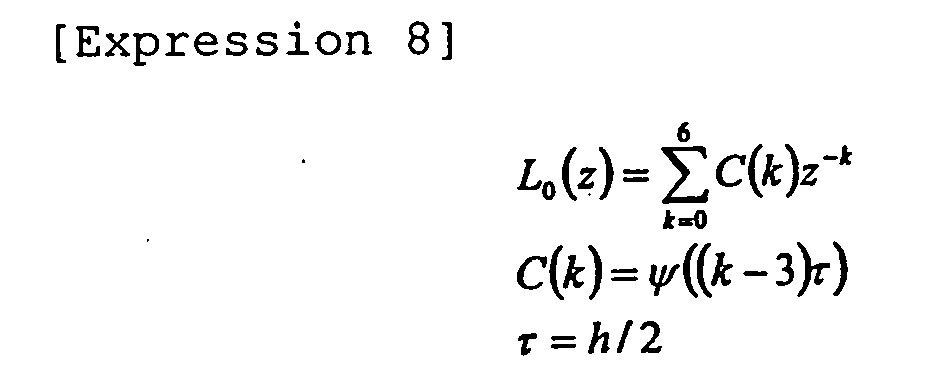
A black dot in the figure indicates a sample point (singular point) in the impulse response function with finite support. When the shown function ψ(t) is given as the waveform of impulse response having a finite support, if the value of the black dot on the vertical axis is given as the filter coefficient (tap coefficient) C(k) with the filter delay time treated as a half of the sampling time width h, the waveform of the lowest-degree impulse response is reproduced. A filter having this filter coefficient C(k) is called a basic low-pass filter L0. - With the shown function ψ, the basic low-pass filter is expressed as follows.
In the equation given above, the value of ψ(t) at connection points at intervals of h/2 in each section as shown inFig. 7 is taken as the coefficient C(k), with the following settings being taken intoaccount 




-
Fig. 8 is a view showing an example of the frequency response of the low-pass filter of the embodiment. The figure shows the characteristics expressed by the equation given above. -
Fig. 9 is a structural view of the basic low-pass filter of the embodiment.
An example of the arithmetic circuit of the basic low-pass filter L0 is configured as shown inFig. 9 .
The basic low-pass filter includes delay elements 91-1, 91-2, 91-3, 91-4, 91-5, and 91-6, multipliers 92-1, 92-2, and 92-3, and adders 93-1, 93-2, 93-3, and 93-4. The filter coefficients of the multipliers 92-1, 92-2, and 92-3 are - 1/16, 9/16, and 1, respectively. The multiplier 92-3 can be omitted because the coefficient is 1.
Based on the low-pass filter L0(z), a basic high-pass filter H0(z) can be expressed by the following equation.
-
Fig. 10 is an illustration of the discrete impulse response and filter coefficient value of the basic high-pass filter of the embodiment.
The coefficient b(k) in the equation given above is obtained by inverting the sign of the coefficient C(k) alternately as shown inFig. 10 . -
Fig. 11 is a view showing an example of the frequency response of the basic high-pass filter of the embodiment.
The high-pass filter H0(z) has frequency characteristics shown inFig. 11 and can be expressed by the equation given below.
- In comparison with the basic filters described above, a filter with a time base multiplied by M + 1, or a filter having a delay time interval multiplied by 1/(M + 1) will now be considered In other words, a filter scaled in the frequency domain as given by the equation given later is defined. LM(z) and HM(z) are obtained by scaling L0(z) and H0(z), respectively by M + 1, where M is referred to as a scaling factor.
- On the basis of the basic low-pass filter L0(z) and basic high-pass filter H0(z), described above, filters scaled in the frequency domain will be defined next.
A low-pass filter LM(z) and a high-pass filter HM(z) obtained by scaling the basic low-pass filter L0(z) and the basic high-pass filter H0(z) by M + 1 can be expressed respectively by the following equations.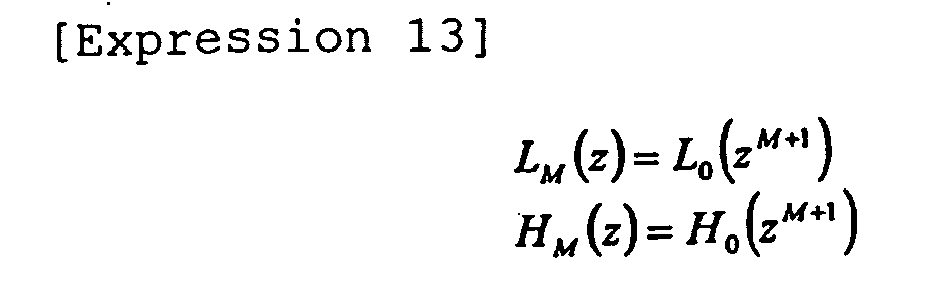
-
Fig. 12 is an illustration of scaling by M in the embodiment.
As the equations given above indicate, scaling in the frequency domain corresponds to upsampling in the time domain.
The low-pass filter LM(z) and high-pass filter HM(z) are obtained by upsampling M times in the time domain as shown inFig. 12 , which corresponds to insertion of M zeros between sample points. -
Fig. 13 is an illustration of scaled filters in the embodiment.
Examples of the frequency characteristics of the low-pass filter LM(z) are shown inFig. 13 .
The figure shows the characteristics of filters L1 and L2 obtained by scaling the basic low-pass filter L0 by 2 and 3, respectively.
The basic filter L0 is scaled to the filter L1 as shown in the figure, and the filter L1 is scaled to the filter L2 as shown in the figure. A filter L3 and subsequent filters are obtained likewise by scaling. - The configuration of an example arithmetic circuit of LM(z) will now be described. A filter Lp(z) formed by scaling by p + 1 will be described below.
Fig. 2 is a structural view of a scaled element filter in the embodiment. The figure shows a filter formed by scaling the basic filter by p + 1.
The basic low-pass filter has delay elements 21-1, 21-2, 21-3, 21-4, 21-5, and 21-6 that cause a delay of p + 1 samples, multipliers 22-1, 22-2, and 22-3, and adders 23-1, 23-2, 23-3, and 23-4. The filter coefficients of the multipliers 22-1, 22-2, and 22-3 are -1/16, 9/16, and 1, respectively. The multiplier 22-3 can be omitted because the coefficient is 1.
This filter has an arithmetic circuit implementing the following equation.
-
Fig. 1 is a structural view of an example filter having a cascade connection of low-pass filters to implement the embodiment.
The filter has n low-pass filters Lpk(z) connected in cascade. The low-pass filter Lpk(z) is an element filter formed by scaling the basic low-pass filter L0(z). Scaling is to define a filter by multiplying the basic filter by pk + 1 in the frequency domain or time domain.
The shown configuration includes just scaled filters based on the low-pass filter. However, a configuration that includes high-pass filters alone or both high-pass filters and low-pass filters, which will be described later, is within the scope of this embodiment. -
Fig. 14 is an illustration of variations in frequency characteristics caused by cascade connections of the basic filters.
By connecting scaled low-pass filters Lpk(z) in cascade as shown inFig. 1 , filters having the frequency characteristics shown inFig. 14 , for example, can be implemented. The cascade connection of scaled filters makes it possible to narrow the passband width and to lower the stopband sufficiently and creates other new characteristics.
In the figure, the filter of a single stage is the basic filter L0; the filter of two stages includes the basic filter L0 and the filter L1 connected in cascade; the filter of three stages includes the basic filter L0, the filter L1, and the filter L2 connected in cascade. As shown in the figure, the cascade connection of scaled filters can narrow the passband width and can also lower the stopband. - The examples described above include just low-pass filters, but generally, a variety of filters X(z) can be configured by combining low-pass filters and high-pass filters. The filter X(z) can be expressed generally by the equation below.

- L0 is the basic low-pass filter (mother filter).
- H0 is the basic high-pass filter (mother filter).
- p and q are scaling values (scaling factors). In other words, a scaled filter is formed by scaling the frequency by p + 1 or q + 1.
- αp is the number of times an identical scaled filter is connected, or the number of connected scaled low-pass filters formed by scaling by p + 1 (exponential value).
- βq is the number of times an identical scaled filter is connected, or the number of connected scaled high-pass filters formed by scaling by q + 1 (exponential value).
- X0(z) is a highest-order filter LP(z) = L0(zP+1) or HQ(z) - H0(zQ+1) that has a target bandwidth (frequency width up to the attenuation of -3 dB, for example). The highest degrees p and q are indicated as P and Q.
- The relationship between the target bandwidth fp and the bandwidth f0 of the mother filter L0 or H0 is expressed by the following equation.
- An example filter configuration method will be described next.
Fig. 15 is an illustration of a band-pass filter of the embodiment. The figure shows the characteristics of the filter to be implemented as a design target.
The requirements of the filter to be implemented include the following items. The corresponding symbols are shown inFig. 15 . - (1) Sampling frequency fs
- (2) Center frequency fc
- (3) Cutoff frequencies (frequencies at which the attenuation is 3 dB) f1, f-1
- (4) Passband frequency width (width of -3 dB band) Δfb
- (5) Stopband frequencies f2, f-2
- (6) Stopband attenuation Ad (dB)
- In a signal pass filter, the sampling frequency fs is the repetition frequency of the signal input to the filter, and the center frequency fc is the frequency at the center of the filter, extracted from the frequency components included in the signal. Generally, fc/fs < 0.5, according to the Nyquist theorem. The cutoff frequency f1 is the highest frequency at which the signal passes. The symmetrical frequency f-1 about the center frequency fc is the lowest frequency at which the signal passes. In the example described here, the attenuation of the passing signal at the cutoff frequencies f1 and f-1 is -3 dB, in comparison with the original signal. An appropriate value other than -3 dB can be specified as the reference value. The attenuation A is defined with the magnitude X of the input signal and the magnitude Y of the filter output signal at the cutoff frequency, as indicated in the equation given below.

The input signal is attenuated to about 70.8% (1/√2) at the cutoff frequencies f1 and f-1, and the result is output. This means that the amplitude energy of the signal is attenuated to a half. - The signal passband is the range between the cutoff frequencies f1 and f-1, and the frequency width Δfb(m) thereof is given by the following equation.

The stopband frequencies f2 and f-2 indicate that the frequency components above f2 or below f-2 of the input signal are cut off. With the corresponding attenuation degree Ad (such as -80 dB) at the stopband frequencies, the transition band attenuation characteristics from the attenuation level (such as -3 dB) at the cutoff frequencies f1 and f-1 to the attenuation degree Ad will be given. An appropriate value other than -80 dB can be specified as the reference value. Ideally speaking, the cutoff frequency should be equal to the stopband frequency. Since that is difficult to realize in actual filters, a transition band is provided. When the attenuation degree Ad in the stopband is -80 dB, the ratio between the input signal X and the filter output signal in magnitude is 0.01% as given below.
- Based on the preconditions described above, the filter configuration in this embodiment will be described next.
Fig. 16 is an illustration of a frequency shift of a band-pass filter in the embodiment.
To simplify the design, a filter B(z) obtained by shifting a band-pass filter BB(z) with the center frequency fc (2πfc = ωc) to the point of frequency zero will be considered, as shown inFig. 16 .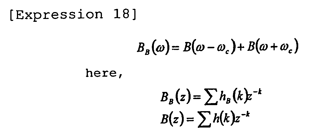

The filter BB(z) is converted by multiplying the coefficient of the filter B(z) by 2cos(ωck).
This means that when the filter B(z) is designed, the requirements should be converted as given below. -
Fig. 21 is an illustration of the band-pass filter of the embodiment. The figure shows the characteristics of the target filter to be implemented. - (1) Sampling frequency fs
- (2)
Center frequency 0 - (3) Cutoff frequencies (frequencies at which the attenuation is 3 dB, for example) fa = Δfb/2, -Δfb/2 = -fa
- (4) Passband frequency width (width of -3 dB band, for example) Δfb
- (5) Stopband frequencies fb = (f2 - f-2)/2, -(f2 - f-2)/2 = -fb
- (6) Stopband attenuation Ad (dB) (-80 dB, for example)
- The cascade connection of filters will be described next.
The general expression is the equation given below.
- Lp(z) is a low-pass filter formed by scaling the basic low-pass filter L0(z) by p + 1.
- Hq(z) is a high-pass filter formed by scaling the basic high-pass filter H0(z) by q + 1.
-
Fig. 17 is an illustration of the relationship between the passband frequency width and scaling factor in this embodiment.
The maximum scaling value M is determined by a required passband frequency width Δfb. The passband width Δfb narrows with an increase in scaling value, as clearly indicated inFig. 13 , and the relationship between Δfb and the scaling value p (or q) is as shown inFig. 17 . The attenuation degree is the ratio of the output Y(m) to the input x(m), or Y(m)/x(m) = Lp(z). The attenuation degree is calculated in decibels (dB) as follows. The Δfb-p relationship satisfies the following.

In this embodiment, a low-pass filter LM(z) or a high-pass filter HM(z), where p, q = M, is used as an initial value, for example. Then, p or q is selected in descending order, for example; an optimum combination of p, q, αp, and βq is selected; and B(z) is designed.
Lp(z) or Hp(z) is selected in accordance with whether the attenuation degree at the stopband frequency fb is equal to or smaller than the required value Ad (such as -80 dB). In addition, a filter with the attenuation degree required at the cutoff frequency fa much lower than the value (-3 dB, for example) will not be selected.
The filter BB(z) to be selected according to the criteria given above is expressed as follows.
By multiplying the coefficients of the filters Lp(z) and Hq(z) by 2cos(ωck), LpB(z) and HqB(z), which form BB(z), are obtained. -
Fig. 19 is a view showing an example configuration of the band-pass filter according to the embodiment.
The band-pass filter is designed in the method described above in accordance with the configuration shown in the figure.
The filter includes a filter B0(z) having the maximum scaling value, a filter containing low-pass filters L0B to LpB formed by scaling by 0B to pB, respectively, connected in αp stages in cascade, and a filter containing high-pass filters H0B to HqB formed by scaling by 0B to qB, respectively, connected in βq stages. -
Fig. 20 is a structural view of a low-pass filter LpB(z) formed by scaling by p + 1.
The low-pass filter includes delay elements 201-1, 201-2, 201-3, 201-4, 201-5, and 201-6, which cause a delay of p + 1 samples, multipliers 202-1, 202-2, and 202-3, and adders 203-1, 203-2, and 203-3, and multipliers 205-1, 205-2, and 205-3. The filter coefficients of the multipliers 202-1, 202-2, and 202-3 are -1/16, 9/16, and 1, respectively. The coefficients of the multipliers 205-1, 205-2, 205-3 are 2(1 + cos(6ωc)), 2(cos(2ωc) + cos(4ωc)), and 2cos(3ωc), respectively. The multiplier 202-3 can be omitted because the coefficient is 1. Pairs of multipliers 202-1 and 205-1, multipliers 202-2 and 205-2, multipliers 203-3 and 205-3 can be configured as integrated multipliers. -
Fig. 26 is a structural view of a high-pass filter HqB(z) formed by scaling by q + 1.
The high-pass filter includes delay elements 201-1, 201-2, 201-3, 201-4, 201-5, and 201-6, which cause a delay of q + 1 samples, multipliers 202-1, 202-2, and 202-3, adders 203-1, 203-2, and 203-3, and multipliers 205-1, 205-2, and 205-3. The filter coefficients of the multipliers 202-1, 202-2, and 202-3 are 1/16, -9/16, and 1, respectively. The coefficients of the multipliers 205-1, 205-2, and 205-3 are 2 (1 + cos(6ωc)), 2(cos(2ωc) + cos(4ωc)), and 2cos(3ωc), respectively. The multiplier 202-3 can be omitted because the coefficient is 1. Pairs of multipliers 202-1 and 205-1, multipliers 202-2 and 205-2, multipliers 203-3 and 205-3 can be configured as integrated multipliers. - Other filter circuit configurations will be described next.
Fig. 22 is a structural view of the basic low-pass filter L0B(z).
The basic low-pass filter L0B(z) expressed by the equation given above has the shown circuit configuration.
The basic low-pass filter includes delay elements 21-1, 21-2, 21-3, 21-4, 21-5, and 21-6, which cause a delay of a single sample, multipliers 22-1, 22-2, 22-3, 22-4, and 22-5, and adders 23-1, 23-2, 23-3, and 23-4. The filter coefficients of the multipliers 22-1, 22-2, 22-3, 22-4, and 22-5 are -1/8, 9cos(2ωc)/8, 2cos(3ωc), 9cos(4ωc)/8, and - cos(6ωc)/8, respectively. -
Fig. 23 is a structural view of the low-pass filter LpB(z) formed by scaling by p + 1.
As shown in the figure, the low-pass filter LpB(z) formed by scaling by p + 1 has the same structure as LOB, but z-1 is replaced with Z-(p+1).
The low-pass filter formed by scaling by p + 1 includes blocks 31-1, 31-2, 31-3, 31-4, 31-5, and 31-6 having p + 1 delay elements, multipliers 32-1, 32-2, 32-3; 32-4, and 32-5, and adders 33-1, 33-2, 33-3, and 33-4. The filter coefficients of the multipliers 32-1, 32-2, 32-3, 32-4, and 32-5 are -1/8, 9cos(2ωc)/8, 2cos(3ωc), 9cos(4ωc)/8, and - cos(6ωc)/8, respectively.
In the figure, the delay elements 31-1 to 31-6 each have p + 1 delay elements. Each delay element block may have any number of delay elements, if they cause a delay of p + 1 samples. -
Fig. 24 is a structural view of the basic high-pass filter H0B(z).
The basic high-pass filter H0B(z) has the shown circuit configuration.
The basic high-pass filter has delay elements 41-1, 41-2, 41-3, 41-4, 41-5, and 41-6 that cause a delay of a single sample, multipliers 42-1, 42-2, 42-3, 42-4, and 42-5, and adders 43-1, 43-2, 43-3, and 43-4. The filter coefficients of the multipliers 42-1, 42-2, 42-3, 42-4, and 42-5 are 1/8, -9cos(2ωc)/8, 2cos(3ωc), -9cos(4ωc)/8, and cos(6ωc)/8, respectively. -
Fig. 25 is a structural view of the high-pass filter HqB(z) formed by scaling by q + 1.
The high-pass filter HqB(z) formed by scaling by q + 1 has the same structure as the filter H0 as shown in the figure, but Z-1 is replaced with Z-(q+1).
The high-pass filter formed by scaling by q + 1 includes blocks 51-1, 51-2, 51-3, 51-4, 51-5, and 51-6 that have q + 1 delay elements, multipliers 52-1, 52-2, 52-3, 52-4, and 52-5, and adders 53-1, 53-2, 53-3, and 53-4. The filter coefficients of the multipliers 52-1, 52-2, 52-3, 52-4, and 52-5 are 1/8, -9cos(2ωc)/8, 2cos(3ωc), -9cos(4roc)/8, and cos(6ωc)/8, respectively.
In the figure, the delay elements 51-1 to 51-6 each have q + 1 delay elements. Each delay element block may have any number of delay elements, if they cause a delay of q + 1 samples. -
Fig. 32 is a structural view of the hardware of a design system according to the embodiment.
The design system includes aprocessing unit 1, which is a central processing unit (CPU), aninput unit 2, anoutput interface unit 3, adisplay unit 4, a storage unit 5, and afilter circuit 6. Theprocessing unit 1,input unit 2,output interface unit 3,display unit 4, and storage unit 5 are connected by a star, bus, or another connection means.
Theprocessing unit 1 accesses the storage unit 5 and executes filter design processing.
The storage unit 5 includes afilter configuration file 51 that stores design specifications and requirements (such as conditions (range, value, ratio, etc) of the passband and stopband, upper limits of the numbers αp and βq of filters connected in cascade), a basic filter characteristics file 52 that stores the characteristics of the basic low-pass filter, the low-pass filters L0 to Lp formed by scaling the basic low-pass filter, the low-pass filter LpB formed by multiplying the filter coefficient of the filter Lp by 2cos(ωck), the basic high-pass filter, the high-pass filters H0 to Hq formed by scaling the basic high-pass filter, and the high-pass filter HqB formed by multiplying the filter coefficients of filter Hq by 2cos(ωck), and afilter output file 53 that stores data and parameters (such as the shift amount B, maximum scaling value M, filter coefficients p, q, ωp, βq of multipliers) for determining a designed filter configuration and intermediate results, final results, and so on by theprocessing unit 1, such as designed filter characteristics. Theprocessing unit 1 can output these data items (for example, data and parameters for determining the filter configuration, such as the filter coefficients of multipliers) through theoutput interface unit 3 to thefilter circuit 6. Thefilter circuit 6 is provided by software or hardware and implements a filter having the specified characteristics in accordance with the data items set up through theoutput interface unit 3 by theprocessing unit 1. -
Fig. 18 is a flowchart illustrating a processing procedure in the embodiment.
The design system configures a filter through steps S01 to S07 described below. - The
processing unit 1 specifies beforehand desired characteristics data to be given as design specifications and requirements, including the center frequency fc, cutoff frequency f1, stopband frequency f2, passband attenuation degree A, stopband attenuation degree Ad, and sampling frequency fs, for example, by storing them in the storage unit 5 (filter configuration file 51) through operations from theinput unit 2 or by reading the values stored in the storage unit 5 (filter configuration file 51) beforehand. - The
processing unit 1 reads the values of characteristics data specified in step S01, from the storage unit 5 (filter configuration file 51), and calculates the shift amount B, which shifts the center frequency fc to the origin O, by the equation given below, in accordance with the input characteristics data.
B = [fc/fs] (The square brackets indicate that fractions are rounded off to the whole numbers.)
Theprocessing unit 1 stores the obtained shift amount B in the storage unit 5 (filter output file 53).
Theprocessing unit 1 also converts the center frequency fc, cutoff frequency f1, and stopband frequency f2 of the input characteristics data to thecenter frequency 0, cutoff frequency fa, and stopband frequency fb, respectively, in accordance with the shift amount B, and stores the values in the storage unit 5 (filter output file 53).
Theprocessing unit 1 reads the values of the characteristics data specified in step S01, from the storage unit 5 (filter configuration file 51), and calculates the scaling value (scaling factor) M of the highest degree on the basis of the input characteristics data.
To obtain the scaling value M of the highest-degree (maximum scaling value), the processing unit calculates the passband width Δfb(M) of the filter formed by scaling by M + 1, as given below, for example.
Then, theprocessing unit 1 obtains the maximum scaling value M from the passband width Δfb(M) by referencing a scaling curve stored in advance in the storage unit 5 (basic filter characteristics file 52) or by calculating the equation of a scaling curve.
- f-3(Δfb(M)): Scaling curve that causes an attenuation of 3 dB
- [ ]: The square brackets indicate that fractions are rounded off to the whole numbers.
- Δfb(0): Passband width of the basic filter
- Δfb(M) : Passband width of the filter formed by scaling by M + 1
- The
processing unit 1 reads from the storage unit 5 (filterconfiguration file 51 and filter output file 53) the values specified in step S01 and the maximum scaling value M calculated in step S03. Theprocessing unit 1 also selects from the storage unit 5 an optimum combination of p, q, αp, and βq in accordance with the filter combination as given by the equation below.
Theprocessing unit 1 reads from the storage unit 5 (basic filter characteristics file 52) the characteristics of the low-pass filter Lp and high-pass filter Hq determined by p and q, calculates the characteristics of B(z) on the basis of the equation given above, and selects values conforming to the passband and stopband design specifications on a round-robin basis. Theprocessing unit 1 may further select values that minimize the number of multipliers.
The selection of Lp(z) and Hp(z) is made, depending on whether the attenuation degree at the stopband frequency fb is lower than or equal to the required value Ad (for example, -80 dB), and, at the same time, depending on it that a filter with an attenuation degree much lower than the required value (for example, -3 dB) at the cutoff frequency fa will not be selected (for example, a filter below a predetermined permissible level will not be selected). Thus, theprocessing unit 1 selects an optimum combination of p, q, αp, and βq.
The maximum values of αp and βq can be specified beforehand in the storage unit 5 (filter configuration file 51) or the like, and theprocessing unit 1 can select an optimum combination of p, q, αp, and βq by selecting αp and βq in descending order from the stored maximum values and selecting p and q in descending order from the maximum scaling value M.
Here, the processing unit may make the following judgment or processing.
(The maximum attenuation is judged by Xd = X(z) at f = fs/(p + 1): When Xd decreases at f = f2, α and β are increased; When Xd decreases at f = f1 added Lp and Hp are deleted.)
In the description given above, the characteristics of filters formed by scaling the basic low-pass filter and basic high-pass filter are stored beforehand in the storage unit 5 (basic filter characteristics file 52). However, the characteristics of just the basic low-pass filter and the basic high-pass filter may be stored in the basic filter characteristics file 52, and theprocessing unit 1 may obtain the characteristics of a desired scaled filter through scaling based on the stored characteristics as necessary and use those characteristics.
Theprocessing unit 1 stores the obtained p, q, αp, and βq in the storage unit 5 (filter output file 53). - The
processing unit 1 reads from the storage unit 5 (filter output file 53) the specification data and parameters for configuring the filter, such as p, q, αp, and βq, reads further from the storage unit 5 (basic filter characteristics file 52) the characteristics of the filter L0M or filter H0M corresponding to B0(z), according to the low-pass filter or the high-pass filter, and the characteristics of the filter LpB and filter HqB, forms the filter BB(z) in accordance with the equation given below, and displays on thedisplay unit 4 the filter characteristics and the parameters and data that are used or stores them in the storage unit 5 (filter output file 53), or both displays and stores them.
processing unit 1 can also read from the storage unit 5 (filter output file 53) the specification data and parameters for configuring the filter, such as p, q, αp, and βq, read from the storage unit 5 (basic filter characteristics file 52) the characteristics of the filters LpB and HqB, and output the values through theoutput interface unit 3 to thefilter circuit 6. Theprocessing unit 1 may use thefilter circuit 6 to form the filter BB(z) in accordance with the read values. Thefilter circuit 6 can form the filter BB(z) with a computer simulation or by software. Thefilter circuit 6 may be configured by hardware to form the filter BB(z) in accordance with the values output from theoutput interface unit 3. - A quantization expansion method for filter coefficients will be described next.
The quantization expansion method here means a method of implementing the same characteristics as the impulse response characteristics of the filter designed to include the cascade connection configuration, as described above, by a shown filter circuit configuration.
Since Lp(z) = L0(zp+1), an impulse signal is input to the filter designed to include the cascade connection given below to obtain the response.

-
Fig. 27 shows a filter structural diagram.
The filter includes multipliers 72-0 to 72-k, delay elements 71-1 to 71-k that cause a delay of a single sample, and adders 73-1 to 73-k.
For example, theprocessing unit 1 reads data (filter coefficients, p, q, αp, βq, etc.) for configuring the filter from the storage unit 5 (filter output file 53), obtains the impulse response by using thefilter circuit 6 or the like, and stores the coefficient Ck of the impulse response in the storage unit 5 (filter output file 53).
Since theprocessing unit 1 reads the filter coefficient from the storage unit 5 and uses thefilter circuit 6, the coefficients Ck (k + 1 coefficients) can be used as the filter coefficients (tap coefficients) in the shown circuit configuration, and the filter can be configured by using k delay elements z-1. -
Fig. 28 shows another filter structural diagram.
The filter includes multipliers 82-0 to 82-M, delay elements 81-1 to 81-M, and anadder 83.
A filter having characteristics designed in accordance with the filter coefficient Ck obtained as described above can be configured as shown in the figure besides the filter configuration described earlier. - The method according to this embodiment will be compared with a conventional method below.
The requirements in the embodiment are as listed below.
Sampling frequency: 1.8 MHz
Center frequency: 450 kHz
-3 dB bandwidth: 6 kHz
-80 dB bandwidth: 12 kHz
Quantization bit rate: 18 bits
Phase characteristics: Linear phase -
Fig. 29 is a frequency characteristics diagram of filters designed with theoretical values by different methods.
As the left graph shows, the Remez method satisfies the requirements but generates ripples in the passband and stopband.
The right graph shows that the filter according to the present invention satisfies the specifications and makes a large attenuation in the stopband. -
Fig. 30 is a frequency characteristics diagram of filters designed by the methods after coefficient quantization.
The left graph clearly shows that the Remez method produces errors throughout the stopband.
The right graph shows that the filter according to the present invention produces just a few errors in the transition band. -
Fig. 31 shows the characteristics of the filter according to the present invention, evaluated against the requirements.
As shown in the figure, the filter according to the present invention can be implemented with a much smaller number of taps in comparison with the conventional method. - A filter configuration (design) method or filter configuration (design) apparatus or system according to the present invention can be provided by a filter configuration (design) program for executing each procedure on a computer, a computer-readable recording medium having the filter configuration (design) program recorded on it, a program product that includes the filter configuration (design) program and can be loaded into the internal memory of the computer, a server or any other computer that includes the program, and the like.
-
Fig. 33 is a circuit diagram of a filter G.
Fig. 34 is a circuit diagram of Gpass.
Figs. 35 and36 are expanded views of Gpass.Figs. 35 shows a part related to a first term of Gpass.Fig. 36 shows a part related a second term of Gpass.
With Lm and Hm described above, the filter passband main part Gpass is formed as indicated below.
Gpass is expressed by the equation given below.
- αP, βP: Exponential value (indicating that identical LP,N1 or [1 - HP,N2] is connected αP or βP times. Here, N1 = Np (1) and N2 = Np (2) for the sake of convenience of description),
- NP (1) : Number of HP ladder connection stages in LP,N1 (indicating the number of diagonal connection stages in
Fig. 35 ), - NP (2) : Number of LP ladder connection stages in [1 - HP,N2] (indicating the number of diagonal connection stages in
Fig. 36 ), - P: Filter formed by scaling the frequency by P + 1.
- Scaling is expressed by the equation below.

-
Fig. 37 is a circuit diagram of Gstop.
With Lm and Hm described above, the stopband main part Gstop is also formed as indicated below.
Stop is expressed by the equation given below.
- αk, βl : Exponential value (indicating that identical Lpk,Nk or [1 - Hql,Nl] is connected αk or βl times),
- Nk: Number of Hp ladder connection stages in Lpk,Nk (indicating the number of diagonal connection stages (corresponding to Np (1)) in
Fig. 35 ) - Nl: Number of Lp ladder connection stages in [1 - Hql,Nl] (indicating the number of diagonal connection stages (corresponding to Np (2)) in
Fig. 36 ) - Pk, ql: Filter formed by scaling the frequency by pk + 1 or by ql + 1.
-
Fig. 38 is a structural view of hardware related to the embodiment.
The hardware includes aprocessing unit 1, which is a central processing unit (CPU), aninput unit 2, anoutput interface unit 3, adisplay unit 4, a storage unit 5, and afilter circuit 6. Theprocessing unit 1,input unit 2,output interface unit 3,display unit 4, and storage unit 5 are connected by a star, bus, or another connection means.
The storage unit 5 includes afilter configuration file 51 that stores design specifications and requirements (such as conditions (range, value, ratio, etc) of the passband and stopband, the upper limit Npass of the number of multipliers, etc.), a basic filter characteristics file 52 that stores the characteristics of the basic low-pass filter, the scaled low-pass filters (L0, L1, ... Lm, ...), the basic high-pass filter, and the scaled high-pass filters (H0, H1, ..., Hm , ...), and afilter output file 53 that stores data and parameters (such as the filter coefficients Npass, Np (1), Np (2)αp, βp, P, Nk, Nl, αpk, βpl, pk, ql of multipliers, etc.) for determining a designed filter configuration, and intermediate results, final results, and so on by theprocessing unit 1, such as the designed filter characteristics. Theprocessing unit 1 can output these data items (for example, data and parameters for determining the filter configuration, such as the filter coefficients of multipliers) through theoutput interface unit 3 to thefilter circuit 6. Thefilter circuit 6 is configured by software or hardware and implements a filter having the specified characteristics in accordance with the data items set up through theoutput interface unit 3 by theprocessing unit 1. -
Fig. 39 is a flowchart of a filter design procedure (low-pass filter).
This flowchart includes the following steps: - 0. Input design specifications (S0)
- 1. Determine the maximum scaling value p = P (S1)
- 2. Configure passband section Gpass (S2)
- 3. Configure stopband section Gstop (S3)
- 4. G = Gpass·Gstop (S4)
- The steps will be described next in detail.
0. Input design specifications (S0)
Theprocessing unit 1 specifies beforehand design specifications (conditions (range, value, ratio, etc) of the passband and stopband, the upper limit Npass of the number of multipliers, etc.) by storing them in the storage unit 5 (filter configuration file 51) through operations from theinput unit 2 or by reading the values stored in the storage unit 5 (filter configuration file 51) beforehand. -
Fig. 40 is a graph showing the cutoff characteristics of a cascade connection model G(f) of a product-sum module.
In the figure, f3 and f80 indicate the following: - f3: Frequency that crosses the -3 dB line (point of frequency crossing the -3 dB line first on the right of f = 0)
- f80: Frequency that crosses the -80 dB line (point of frequency crossing the -80 dB line first on the left of f = fs/2)
- Passband: -3 dB or higher at [0, f3]
- Stopband: -80 dB or lower at [f80, 1]
- R ≤ R0 (The obtained filter ratio R is larger than or equal to a predetermined ratio R0.)
- In step S1, the
processing unit 1 reads specified values such as f3 from the storage unit 5 (filter configuration file 51) and selects the maximum scaling value p = P in accordance with the given f3. Theprocessing unit 1 may allow the P value to be predetermined by theinput unit 2 or storage unit 5 (filter output file 53).
Theprocessing unit 1 regards f3 (p) as the -3 dB point of Lp, calculates f3 (0) in advance, and specifies the minimum value of p that satisfies the following as P.
Theprocessing unit 1 stores the obtained value of P in the storage unit 5 (filter output file 53). - Step S2. Configure the passband main part The
processing unit 1 reads the values specified in step S1, such as Npass and R0, from the storage unit 5 (filterconfiguration file 51, filter output file 53) and selects a set of values that satisfies the design specifications (R ≥ R0, for example) and minimizes the number of multipliers on a round-robin basis of

For example, theprocessing unit 1 reads the characteristics of the low-pass filter and high-pass filter determined by Np (1), Np (2), αp, βp, from the storage unit 5 (basic filter characteristics file 52), calculates the characteristics of Gpass by the equation given above, and selects the set that satisfies the design specifications (R ≥ R0, for example) and minimizes the number of multipliers on a round-robin basis. Theprocessing unit 1 may select a set that also conforms to the design specifications of the passband and stopband.
However, the following rules of combination are defined.


The numbers of multipliers are obtained as follows.

processing unit 1 stores the obtained Np (1), Np (2), αp, βp in the storage unit 5 (filter output file 53). - Step S3. Configure stopband section The
processing unit 1 selects a set of values that satisfies the design specifications (R ≥ R0, for example) and minimizes the number of multipliers by calculating


For example, theprocessing unit 1 reads the characteristics of the low-pass filter and high-pass filter determined by Nk, Nl, αpk, βql from the storage unit 5 (basic filter characteristics file 52), calculates the characteristics of Gstop by the equation given above, calculates
processing unit 1 may select a set that also conforms to the design specifications of the passband and stopband.
Theprocessing unit 1 stores the obtained Nk, Nl, αpk, βql in the storage unit 5 (filter output file 53). - The
processing unit 1 reads from the storage unit 5 (filter output file 53) the specifications data and parameters for configuring the filter, such as Np (1), Np (2), αp, βp, Nk, Nl, αpk, βql, reads also from the storage unit 5 (basic filter characteristics file 52) the characteristics of the basic low-pass filter, the corresponding filters formed by scaling it, the basic high-pass filter, and the corresponding filters formed by scaling it, forms Gpass and Gstop as expressed by the equations given above, forms the filter G by calculating G = GpassGstop, and displays the characteristics of the filter G on thedisplay unit 4 or stores the characteristics in the storage unit 5 (filter output file 53) or both displays and stores them.
Theprocessing unit 1 reads from the storage unit 5 (filter output file 53) the specifications data and parameters for configuring the filter, such as Np (1), Np (2), αp, βp, Nk, Nl, αpk, βql, and outputs the values through theoutput interface unit 3 to thefilter circuit 6. Then, theprocessing unit 1 may form Gpass and Gstop by thefilter circuit 6 in accordance with the read values and equations given above to form the filter G as G = GpassGstop. Thefilter circuit 6 can form the filter G with a computer simulation or by software. Thefilter circuit 6 may also form the filter G by hardware, in accordance with the values output from theoutput interface unit 3.
In the description given above, the characteristics of filters formed by scaling the basic low-pass filter and the basic high-pass filter are stored in advance in the storage unit 5 (basic filter characteristics file 52). However, the characteristics of just the basic low-pass filter and the basic high-pass filter may be stored in the basic filter characteristics file 52, and theprocessing unit 1 may perform scaling based on the stored characteristics as needed to obtain and use the characteristics of a designated scaled filter. -
Fig. 45 is an illustration of an example (low-pass filter) in which the characteristics are improved by G(f).
The figure shows the characteristics of the filter G obtained by forming the filter G(f) given by the equation below, by connecting the low-pass filters L0(f) and L1(f) in cascade.
The characteristics can be made steeper by connecting element filters in cascade. -
Fig. 41 is an illustration of the specifications of a low-pass filter.
An example configuration of the low-pass filter will now be given in accordance with the configuration means described above. The desired characteristics specifications are as shown in the figure. The passband and stopband are ranges of normalized frequency.
The configuration of the filter designed in accordance with the flowchart in this embodiment is expressed as follows.
In this example, P = 7 is selected; α7 = 0, 1, 2, 3, 4 and N7 = 0, 1, 2, 3, and so on are tested; and Gpass = L37.9 is specified. -
Fig. 42 is an illustration of Gpass and Gstop of the filter G.
The characteristics diagram of Gpass is shown inFig. 42 (a) . The characteristics of Gpass include a passband section of [0, 0.096], a stopband section of [0.013, 1], and R = 0.738, and 150 multipliers are used.
In the stopband, the second to fourth side lobes of Gpass must be blocked. The third and fourth side lobes are generally blocked by (1 - H1 1.1) and (1 - H1 2.1) inFig. 26(b) . Here, P ≤ 5 is taken, and, as shown inFig. 26(b) , a part near the center of the second side lobe is blocked by L1 3.1 and L1 4.2, and a part near the right side is blocked by L1 3.1 and 1 - H1 2.1. To stop a part near the left side, N5 = 0, 1, 2, ... and α5 = 0, 1, 2, etc. are tested against p = 5, and (α5, N5) = (1, 3) is selected in keeping with the number of multipliers. -
Fig. 43 is a characteristics diagram of filters configured by conventional methods and the present invention. The least squares method is shown at (a); the Remez method is shown at (b); and the method of the present invention is shown at (c). -
Fig. 44 is a chart comparing the number of multipliers and R of the design methods. The number of multipliers here was obtained when the characteristics satisfied all the specifications for the first time. The method of the present invention is superior to the least squares method in terms of both the number of multipliers and R. The Remez method is slightly better than the method according to the present invention in R, but the number of multipliers is as large as 1142. To check superiority to the Remez method, the number of multipliers was calculated when the R value exceeded R = 0.762 of the Remez method (R = 0.767, here). It was 365.
This result verifies the validity of the approximation model of steep low-pass filter characteristics, made by a cascade connection of element filters formed of the product-sum modules according to the present invention. - As the impulse response function described above, an m-th-degree piecewise polynomial can be used, for example. An interpolation function with waveform adjustment parameters or the like can also be used.
The present invention can be applied to a variety of technologies such as acoustic technologies, video technologies, image technologies, transmission technologies, communication technologies, analog-to-digital conversion and digital-to-analog conversion technologies, compression and decompression technologies, encryption and decryption (decompression) technologies, and filter technologies.
The present invention can be used in acoustic, image, communication, and other signal processing filters in wide areas.
The present invention can be used in wide range of apparatuses such as acoustic equipment that includes amplifiers, image apparatuses for moving or still picture processing, communication devices such as mobile phones, controllers, computers, and PCs.
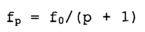
Advantages of the cascade connection include the reduction of the bandwidth in the passband and the attenuation of an unnecessary-signal band in the stopband. Making use of these advantages, the embodiment configures a filter with a reduced number of taps.
A filter B0(z) of low-pass filter type is LM(z), and a filter B0(z) of high-pass filter type is HM(z).
The
The

As the value of R approaches 1, the steepness increases. Steep cutoff characteristics is expressed by the ratio R (0 < R ≤ 1) between f3 and f80, as in the equation given below, for example.

The


Claims (15)
- A filter providing desired characteristics by combining:a basic low-pass filter or a basic high-pass filter using a nodal value of an impulse response function configured by a piecewise polynomial with a finite support as a filter coefficient; anda plurality of scaled filters formed by scaling the basic filter in the time domain or the frequency domain.
- A filter according to Claim 1, wherein the scaled filters are combined in a cascade connection.
- A filter according to one of Claim 1 or 2, wherein signals delayed by multiplying an discrete input in a finite interval by a coefficient are added sequentially in a basic structure; the scaled filters are formed by increasing or decreasing the number of delay elements in the basic structure; and the scaled filters are connected in cascade to output the signals.
- An FIR filter providing desired characteristics by combining:a basic low-pass filter or a basic high-pass filter using a nodal value of an impulse response function configured by a piecewise polynomial with a finite support as a filter coefficient; anda plurality of scaled filters formed by scaling the basic filter in the time domain or the frequency domain;wherein a center frequency, a cutoff frequency, a stopband frequency, the maximum attenuation degree in a stopband, and a sampling frequency are input;the maximum scaling degree is determined from a passband frequency width determined by the cutoff frequency and the center frequency;scaled filters having a degree lower than the maximum scaling degree are sequentially selected;it is determined whether scaled filters selected to keep an attenuation degree at the stopband frequency of the FIR filter to be obtained lower than or equal to the maximum attenuation degree are employed; andthe FIR filter is configured by a cascade connection of the scaled filters.
- A filter according to Claim 4, wherein the filter coefficient is quantized, the passband frequency width, an attenuation degree at the cutoff frequency, and the stopband attenuation degree are re-calculated by the quantized coefficient, and the scaled filters to be combined are increased or decreased to keep an error of each of the above values caused by quantization within a permissible range.
- A filter according to Claim 4, wherein the maximum degree of scaling is determined from the ratio between the passband frequency width of the basic filter and the passband frequency width of the filter to be obtained.
- A filter according to Claim 4, wherein a filter gain at a frequency determined by the ratio of the sampling frequency and (scaling factor + 1) is obtained as the maximum stopband attenuation degree.
- A filter according to Claim 4, wherein an identical scaled filter is connected in cascade if a filter gain at the stopband frequency of the filter decreases when the selected scaled filter is connected.
- A filter according to Claim 1, wherein an input signal delayed by the number of delay elements obtained as the ratio between a sampling frequency and a desired center frequency is input to the filter to make it a bandpass filter.
- A filter according to Claim 1, wherein the plurality of scaled filters are connected in ascending order of degree.
- A filter according to Claim 1, wherein scaled filters formed by scaling the low-pass filter and the high-pass filter in frequency are selected such that the passband width is equal to a predetermined required width or larger, and, by connecting the selected scaled filters in cascade, a passband filter is formed such that the passband characteristics satisfy predetermined required characteristics and a stopband filter is formed such that the stopband characteristics satisfy predetermined required characteristics.
- A filter according to Claim 1, wherein scaled filters formed by scaling the low-pass filter and the high-pass filter in frequency are selected such that the passband width is equal to a predetermined required width or larger, and, by the selected scaled filters, filter passband characteristics are provided, by selecting a scaled low-pass filter that satisfies required characteristics, and connecting the scaled high-pass filters in a ladder manner to the selected scaled low-pass filter.
- A filter according to Claim 1, wherein scaled filters formed by scaling the low-pass filter and the high-pass filter in frequency are selected such that the passband width is equal to a predetermined required width or larger, and, by the selected scaled filters, filter passband characteristics are provided, by selecting a scaled high-pass filter that satisfies required characteristics, and connecting the scaled low-pass filters in a ladder manner to the selected scaled high-pass filter.
- A filter according to one of Claims 11 to 13, wherein a correction filter whose required characteristics are equal to stopband characteristics is formed by the scaled filters, and the correction filter is connected to the passband characteristics filter in cascade.
- A filter according to one of Claims 1 to 14, wherein as the maximum degree of scaling that satisfies a predetermined passband width, the maximum scaling value P is the minimum value of p that satisfies the following expression:

where f3 is a frequency (given by design specifications) that crosses a -3 dB line, f3 (0) is a (predetermined) -3 dB point of Lp, and f3 (p) is a -3 dB point of Lp.
Applications Claiming Priority (3)
| Application Number | Priority Date | Filing Date | Title |
|---|---|---|---|
| JP2008151982A JP4968850B2 (en) | 2008-06-10 | 2008-06-10 | Filter, filter design system, design method, and design program |
| JP2008200907A JP2010041311A (en) | 2008-08-04 | 2008-08-04 | Filter, and configuration system and configuration method of filter |
| PCT/JP2009/059953 WO2009150949A1 (en) | 2008-06-10 | 2009-06-01 | Filter |
Publications (3)
| Publication Number | Publication Date |
|---|---|
| EP2315353A1 true EP2315353A1 (en) | 2011-04-27 |
| EP2315353A4 EP2315353A4 (en) | 2013-07-03 |
| EP2315353B1 EP2315353B1 (en) | 2020-07-29 |
Family
ID=41416660
Family Applications (1)
| Application Number | Title | Priority Date | Filing Date |
|---|---|---|---|
| EP09762379.7A Not-in-force EP2315353B1 (en) | 2008-06-10 | 2009-06-01 | Filter |
Country Status (3)
| Country | Link |
|---|---|
| US (1) | US8949303B2 (en) |
| EP (1) | EP2315353B1 (en) |
| WO (1) | WO2009150949A1 (en) |
Cited By (2)
| Publication number | Priority date | Publication date | Assignee | Title |
|---|---|---|---|---|
| CN103684348A (en) * | 2013-12-31 | 2014-03-26 | 中国人民解放军国防科学技术大学 | Multiplication removal rapid algorithm on basis of second-order IIR (Infinite Impulse Response) low pass filter |
| CN107979712A (en) * | 2016-10-20 | 2018-05-01 | 上海富瀚微电子股份有限公司 | A kind of vedio noise reduction method and device |
Families Citing this family (3)
| Publication number | Priority date | Publication date | Assignee | Title |
|---|---|---|---|---|
| US8953716B1 (en) * | 2011-09-14 | 2015-02-10 | Marvell International Ltd. | DC offset estimation and compensaton for wideband systems |
| TWI571052B (en) * | 2015-09-30 | 2017-02-11 | 國立彰化師範大學 | Serial finite impulse response filter and signal processing method thereof |
| WO2017152059A1 (en) * | 2016-03-04 | 2017-09-08 | University Of Tennessee Research Foundation | Ambulatory seizure monitoring system and method |
Family Cites Families (18)
| Publication number | Priority date | Publication date | Assignee | Title |
|---|---|---|---|---|
| JPS63269613A (en) | 1987-04-28 | 1988-11-07 | Kenwood Corp | Digital filter |
| JPH0770957B2 (en) | 1988-04-26 | 1995-07-31 | パイオニア株式会社 | FIR filter |
| JPH0760990B2 (en) | 1989-02-23 | 1995-06-28 | エルエスアイ・ロジック株式会社 | Digital filter |
| SE467680B (en) | 1990-12-19 | 1992-08-24 | Johan Hellgren | DIGITAL FILTER BANK WITH Diminished Power Consumption |
| US5212659A (en) | 1991-10-08 | 1993-05-18 | Crystal Semiconductor | Low precision finite impulse response filter for digital interpolation |
| JP4023842B2 (en) | 1995-09-28 | 2007-12-19 | ソニー株式会社 | Digital filter and sound reproduction device |
| US6748409B1 (en) * | 1998-01-26 | 2004-06-08 | Niigata Seimitsu Co., Ltd. | Data interpolating system |
| JP2001084242A (en) | 1999-09-10 | 2001-03-30 | Hitachi Ltd | Variable arithmetic processor |
| JP3686801B2 (en) | 1999-09-27 | 2005-08-24 | 独立行政法人科学技術振興機構 | Filter bank and filtering method |
| JP4397488B2 (en) | 1999-12-17 | 2010-01-13 | Nsc株式会社 | Oversampling circuit and digital-analog converter |
| JP4300272B2 (en) * | 2001-09-10 | 2009-07-22 | Nsc株式会社 | Digital filter and design method thereof |
| KR20050013180A (en) | 2002-07-15 | 2005-02-02 | 유겐가이샤 뉴로솔루션 | Digital filter designing method, digital filter designing program, digital filter |
| US20050120067A1 (en) | 2002-07-15 | 2005-06-02 | Neuro Solution Corp. | Digital filter designing method, digital filter designing program, digital filter |
| TW200414675A (en) | 2002-10-21 | 2004-08-01 | Neuro Solution Corp | Digital filter design method and device, digital filter design program, and digital filter |
| US7529788B2 (en) * | 2002-10-21 | 2009-05-05 | Neuro Solution Corp. | Digital filter design method and device, digital filter design program, and digital filter |
| GB2427093A (en) | 2004-02-17 | 2006-12-13 | Neuro Solution Corp | Digital filter design method and device, digital filter design program, and digital filter |
| JP4461928B2 (en) | 2004-07-05 | 2010-05-12 | 日本電気株式会社 | FIR filter |
| WO2007102611A1 (en) | 2006-03-07 | 2007-09-13 | Neuro Solution Corp. | Interpolation function generation circuit |
-
2009
- 2009-06-01 EP EP09762379.7A patent/EP2315353B1/en not_active Not-in-force
- 2009-06-01 WO PCT/JP2009/059953 patent/WO2009150949A1/en not_active Ceased
- 2009-06-01 US US12/997,233 patent/US8949303B2/en active Active
Cited By (3)
| Publication number | Priority date | Publication date | Assignee | Title |
|---|---|---|---|---|
| CN103684348A (en) * | 2013-12-31 | 2014-03-26 | 中国人民解放军国防科学技术大学 | Multiplication removal rapid algorithm on basis of second-order IIR (Infinite Impulse Response) low pass filter |
| CN107979712A (en) * | 2016-10-20 | 2018-05-01 | 上海富瀚微电子股份有限公司 | A kind of vedio noise reduction method and device |
| CN107979712B (en) * | 2016-10-20 | 2020-02-21 | 上海富瀚微电子股份有限公司 | Video noise reduction method and device |
Also Published As
| Publication number | Publication date |
|---|---|
| US8949303B2 (en) | 2015-02-03 |
| US20110153704A1 (en) | 2011-06-23 |
| EP2315353A4 (en) | 2013-07-03 |
| EP2315353B1 (en) | 2020-07-29 |
| WO2009150949A1 (en) | 2009-12-17 |
Similar Documents
| Publication | Publication Date | Title |
|---|---|---|
| EP2047462B1 (en) | Device and method for processing a real subband signal for reducing aliasing effects | |
| US11263293B2 (en) | Digital sample rate conversion | |
| EP2200180B1 (en) | Subband signal processing | |
| JPH0629786A (en) | Low precision FIR filter for digital interpolation | |
| JP2002374150A (en) | Digital filter and digital signal filtering method | |
| JPH11261376A (en) | Digital IIR filter with few multipliers | |
| EP2315353B1 (en) | Filter | |
| JP2010041311A (en) | Filter, and configuration system and configuration method of filter | |
| EP1808962A1 (en) | Digital filter and its designing method, desiging apparatus, and program for designing digital filter | |
| JPWO2005078925A1 (en) | Digital filter design method and device, digital filter design program, digital filter | |
| US7529788B2 (en) | Digital filter design method and device, digital filter design program, and digital filter | |
| JP4968850B2 (en) | Filter, filter design system, design method, and design program | |
| US10943330B2 (en) | Image processing filter | |
| WO2004079905A1 (en) | Digital filter design method and device, digital filter design program, digital filter | |
| WO2007102611A1 (en) | Interpolation function generation circuit | |
| US7774394B2 (en) | Exponentiated polyphase digital filter | |
| JP4989575B2 (en) | Filter and filter configuration method | |
| US7242326B1 (en) | Sample rate conversion combined with filter | |
| Diaz-Carmona et al. | Fractional delay digital filters | |
| JP6289041B2 (en) | equalizer | |
| US7262717B2 (en) | Sample rate conversion combined with filter | |
| CN101944890B (en) | Audio conversion sampling method and system thereof | |
| US20050171988A1 (en) | Digital filter design method and device, digital filter design program, and digital filter | |
| CN120639067A (en) | Construction method of multi-rate interpolator | |
| JP4456407B2 (en) | Signal processing device |
Legal Events
| Date | Code | Title | Description |
|---|---|---|---|
| PUAI | Public reference made under article 153(3) epc to a published international application that has entered the european phase |
Free format text: ORIGINAL CODE: 0009012 |
|
| 17P | Request for examination filed |
Effective date: 20110110 |
|
| AK | Designated contracting states |
Kind code of ref document: A1 Designated state(s): AT BE BG CH CY CZ DE DK EE ES FI FR GB GR HR HU IE IS IT LI LT LU LV MC MK MT NL NO PL PT RO SE SI SK TR |
|
| AX | Request for extension of the european patent |
Extension state: AL BA RS |
|
| RIN1 | Information on inventor provided before grant (corrected) |
Inventor name: KAWASAKI, SHUJI Inventor name: TORAICHI, KAZUO |
|
| DAX | Request for extension of the european patent (deleted) | ||
| A4 | Supplementary search report drawn up and despatched |
Effective date: 20130604 |
|
| RIC1 | Information provided on ipc code assigned before grant |
Ipc: H03H 17/02 20060101ALI20130528BHEP Ipc: H03H 17/06 20060101AFI20130528BHEP |
|
| STAA | Information on the status of an ep patent application or granted ep patent |
Free format text: STATUS: EXAMINATION IS IN PROGRESS |
|
| 17Q | First examination report despatched |
Effective date: 20180215 |
|
| GRAP | Despatch of communication of intention to grant a patent |
Free format text: ORIGINAL CODE: EPIDOSNIGR1 |
|
| STAA | Information on the status of an ep patent application or granted ep patent |
Free format text: STATUS: GRANT OF PATENT IS INTENDED |
|
| INTG | Intention to grant announced |
Effective date: 20200423 |
|
| GRAS | Grant fee paid |
Free format text: ORIGINAL CODE: EPIDOSNIGR3 |
|
| GRAA | (expected) grant |
Free format text: ORIGINAL CODE: 0009210 |
|
| STAA | Information on the status of an ep patent application or granted ep patent |
Free format text: STATUS: THE PATENT HAS BEEN GRANTED |
|
| AK | Designated contracting states |
Kind code of ref document: B1 Designated state(s): AT BE BG CH CY CZ DE DK EE ES FI FR GB GR HR HU IE IS IT LI LT LU LV MC MK MT NL NO PL PT RO SE SI SK TR |
|
| REG | Reference to a national code |
Ref country code: GB Ref legal event code: FG4D |
|
| REG | Reference to a national code |
Ref country code: CH Ref legal event code: EP |
|
| REG | Reference to a national code |
Ref country code: DE Ref legal event code: R096 Ref document number: 602009062509 Country of ref document: DE |
|
| REG | Reference to a national code |
Ref country code: AT Ref legal event code: REF Ref document number: 1296986 Country of ref document: AT Kind code of ref document: T Effective date: 20200815 |
|
| REG | Reference to a national code |
Ref country code: IE Ref legal event code: FG4D |
|
| REG | Reference to a national code |
Ref country code: LT Ref legal event code: MG4D |
|
| REG | Reference to a national code |
Ref country code: NL Ref legal event code: MP Effective date: 20200729 |
|
| REG | Reference to a national code |
Ref country code: AT Ref legal event code: MK05 Ref document number: 1296986 Country of ref document: AT Kind code of ref document: T Effective date: 20200729 |
|
| PG25 | Lapsed in a contracting state [announced via postgrant information from national office to epo] |
Ref country code: FI Free format text: LAPSE BECAUSE OF FAILURE TO SUBMIT A TRANSLATION OF THE DESCRIPTION OR TO PAY THE FEE WITHIN THE PRESCRIBED TIME-LIMIT Effective date: 20200729 Ref country code: GR Free format text: LAPSE BECAUSE OF FAILURE TO SUBMIT A TRANSLATION OF THE DESCRIPTION OR TO PAY THE FEE WITHIN THE PRESCRIBED TIME-LIMIT Effective date: 20201030 Ref country code: PT Free format text: LAPSE BECAUSE OF FAILURE TO SUBMIT A TRANSLATION OF THE DESCRIPTION OR TO PAY THE FEE WITHIN THE PRESCRIBED TIME-LIMIT Effective date: 20201130 Ref country code: AT Free format text: LAPSE BECAUSE OF FAILURE TO SUBMIT A TRANSLATION OF THE DESCRIPTION OR TO PAY THE FEE WITHIN THE PRESCRIBED TIME-LIMIT Effective date: 20200729 Ref country code: NO Free format text: LAPSE BECAUSE OF FAILURE TO SUBMIT A TRANSLATION OF THE DESCRIPTION OR TO PAY THE FEE WITHIN THE PRESCRIBED TIME-LIMIT Effective date: 20201029 Ref country code: ES Free format text: LAPSE BECAUSE OF FAILURE TO SUBMIT A TRANSLATION OF THE DESCRIPTION OR TO PAY THE FEE WITHIN THE PRESCRIBED TIME-LIMIT Effective date: 20200729 Ref country code: BG Free format text: LAPSE BECAUSE OF FAILURE TO SUBMIT A TRANSLATION OF THE DESCRIPTION OR TO PAY THE FEE WITHIN THE PRESCRIBED TIME-LIMIT Effective date: 20201029 Ref country code: SE Free format text: LAPSE BECAUSE OF FAILURE TO SUBMIT A TRANSLATION OF THE DESCRIPTION OR TO PAY THE FEE WITHIN THE PRESCRIBED TIME-LIMIT Effective date: 20200729 Ref country code: LT Free format text: LAPSE BECAUSE OF FAILURE TO SUBMIT A TRANSLATION OF THE DESCRIPTION OR TO PAY THE FEE WITHIN THE PRESCRIBED TIME-LIMIT Effective date: 20200729 Ref country code: HR Free format text: LAPSE BECAUSE OF FAILURE TO SUBMIT A TRANSLATION OF THE DESCRIPTION OR TO PAY THE FEE WITHIN THE PRESCRIBED TIME-LIMIT Effective date: 20200729 |
|
| PG25 | Lapsed in a contracting state [announced via postgrant information from national office to epo] |
Ref country code: PL Free format text: LAPSE BECAUSE OF FAILURE TO SUBMIT A TRANSLATION OF THE DESCRIPTION OR TO PAY THE FEE WITHIN THE PRESCRIBED TIME-LIMIT Effective date: 20200729 Ref country code: LV Free format text: LAPSE BECAUSE OF FAILURE TO SUBMIT A TRANSLATION OF THE DESCRIPTION OR TO PAY THE FEE WITHIN THE PRESCRIBED TIME-LIMIT Effective date: 20200729 Ref country code: IS Free format text: LAPSE BECAUSE OF FAILURE TO SUBMIT A TRANSLATION OF THE DESCRIPTION OR TO PAY THE FEE WITHIN THE PRESCRIBED TIME-LIMIT Effective date: 20201129 |
|
| PG25 | Lapsed in a contracting state [announced via postgrant information from national office to epo] |
Ref country code: NL Free format text: LAPSE BECAUSE OF FAILURE TO SUBMIT A TRANSLATION OF THE DESCRIPTION OR TO PAY THE FEE WITHIN THE PRESCRIBED TIME-LIMIT Effective date: 20200729 |
|
| PG25 | Lapsed in a contracting state [announced via postgrant information from national office to epo] |
Ref country code: RO Free format text: LAPSE BECAUSE OF FAILURE TO SUBMIT A TRANSLATION OF THE DESCRIPTION OR TO PAY THE FEE WITHIN THE PRESCRIBED TIME-LIMIT Effective date: 20200729 Ref country code: IT Free format text: LAPSE BECAUSE OF FAILURE TO SUBMIT A TRANSLATION OF THE DESCRIPTION OR TO PAY THE FEE WITHIN THE PRESCRIBED TIME-LIMIT Effective date: 20200729 Ref country code: CZ Free format text: LAPSE BECAUSE OF FAILURE TO SUBMIT A TRANSLATION OF THE DESCRIPTION OR TO PAY THE FEE WITHIN THE PRESCRIBED TIME-LIMIT Effective date: 20200729 Ref country code: EE Free format text: LAPSE BECAUSE OF FAILURE TO SUBMIT A TRANSLATION OF THE DESCRIPTION OR TO PAY THE FEE WITHIN THE PRESCRIBED TIME-LIMIT Effective date: 20200729 Ref country code: DK Free format text: LAPSE BECAUSE OF FAILURE TO SUBMIT A TRANSLATION OF THE DESCRIPTION OR TO PAY THE FEE WITHIN THE PRESCRIBED TIME-LIMIT Effective date: 20200729 |
|
| REG | Reference to a national code |
Ref country code: DE Ref legal event code: R097 Ref document number: 602009062509 Country of ref document: DE |
|
| PLBE | No opposition filed within time limit |
Free format text: ORIGINAL CODE: 0009261 |
|
| STAA | Information on the status of an ep patent application or granted ep patent |
Free format text: STATUS: NO OPPOSITION FILED WITHIN TIME LIMIT |
|
| PG25 | Lapsed in a contracting state [announced via postgrant information from national office to epo] |
Ref country code: SK Free format text: LAPSE BECAUSE OF FAILURE TO SUBMIT A TRANSLATION OF THE DESCRIPTION OR TO PAY THE FEE WITHIN THE PRESCRIBED TIME-LIMIT Effective date: 20200729 |
|
| 26N | No opposition filed |
Effective date: 20210430 |
|
| PG25 | Lapsed in a contracting state [announced via postgrant information from national office to epo] |
Ref country code: SI Free format text: LAPSE BECAUSE OF FAILURE TO SUBMIT A TRANSLATION OF THE DESCRIPTION OR TO PAY THE FEE WITHIN THE PRESCRIBED TIME-LIMIT Effective date: 20200729 |
|
| PG25 | Lapsed in a contracting state [announced via postgrant information from national office to epo] |
Ref country code: MC Free format text: LAPSE BECAUSE OF FAILURE TO SUBMIT A TRANSLATION OF THE DESCRIPTION OR TO PAY THE FEE WITHIN THE PRESCRIBED TIME-LIMIT Effective date: 20200729 |
|
| REG | Reference to a national code |
Ref country code: CH Ref legal event code: PL |
|
| REG | Reference to a national code |
Ref country code: BE Ref legal event code: MM Effective date: 20210630 |
|
| PG25 | Lapsed in a contracting state [announced via postgrant information from national office to epo] |
Ref country code: LU Free format text: LAPSE BECAUSE OF NON-PAYMENT OF DUE FEES Effective date: 20210601 |
|
| PG25 | Lapsed in a contracting state [announced via postgrant information from national office to epo] |
Ref country code: LI Free format text: LAPSE BECAUSE OF NON-PAYMENT OF DUE FEES Effective date: 20210630 Ref country code: IE Free format text: LAPSE BECAUSE OF NON-PAYMENT OF DUE FEES Effective date: 20210601 Ref country code: CH Free format text: LAPSE BECAUSE OF NON-PAYMENT OF DUE FEES Effective date: 20210630 |
|
| PG25 | Lapsed in a contracting state [announced via postgrant information from national office to epo] |
Ref country code: BE Free format text: LAPSE BECAUSE OF NON-PAYMENT OF DUE FEES Effective date: 20210630 |
|
| PGFP | Annual fee paid to national office [announced via postgrant information from national office to epo] |
Ref country code: GB Payment date: 20220506 Year of fee payment: 14 Ref country code: FR Payment date: 20220512 Year of fee payment: 14 Ref country code: DE Payment date: 20220506 Year of fee payment: 14 |
|
| PG25 | Lapsed in a contracting state [announced via postgrant information from national office to epo] |
Ref country code: HU Free format text: LAPSE BECAUSE OF FAILURE TO SUBMIT A TRANSLATION OF THE DESCRIPTION OR TO PAY THE FEE WITHIN THE PRESCRIBED TIME-LIMIT; INVALID AB INITIO Effective date: 20090601 Ref country code: CY Free format text: LAPSE BECAUSE OF FAILURE TO SUBMIT A TRANSLATION OF THE DESCRIPTION OR TO PAY THE FEE WITHIN THE PRESCRIBED TIME-LIMIT Effective date: 20200729 |
|
| REG | Reference to a national code |
Ref country code: DE Ref legal event code: R119 Ref document number: 602009062509 Country of ref document: DE |
|
| GBPC | Gb: european patent ceased through non-payment of renewal fee |
Effective date: 20230601 |
|
| PG25 | Lapsed in a contracting state [announced via postgrant information from national office to epo] |
Ref country code: MK Free format text: LAPSE BECAUSE OF FAILURE TO SUBMIT A TRANSLATION OF THE DESCRIPTION OR TO PAY THE FEE WITHIN THE PRESCRIBED TIME-LIMIT Effective date: 20200729 Ref country code: DE Free format text: LAPSE BECAUSE OF NON-PAYMENT OF DUE FEES Effective date: 20240103 Ref country code: GB Free format text: LAPSE BECAUSE OF NON-PAYMENT OF DUE FEES Effective date: 20230601 |
|
| PG25 | Lapsed in a contracting state [announced via postgrant information from national office to epo] |
Ref country code: FR Free format text: LAPSE BECAUSE OF NON-PAYMENT OF DUE FEES Effective date: 20230630 |
|
| PG25 | Lapsed in a contracting state [announced via postgrant information from national office to epo] |
Ref country code: MT Free format text: LAPSE BECAUSE OF FAILURE TO SUBMIT A TRANSLATION OF THE DESCRIPTION OR TO PAY THE FEE WITHIN THE PRESCRIBED TIME-LIMIT Effective date: 20200729 |
|
| PG25 | Lapsed in a contracting state [announced via postgrant information from national office to epo] |
Ref country code: TR Free format text: LAPSE BECAUSE OF FAILURE TO SUBMIT A TRANSLATION OF THE DESCRIPTION OR TO PAY THE FEE WITHIN THE PRESCRIBED TIME-LIMIT Effective date: 20200729 |