EP2314747B1 - Pulsator device usable with washing machine and washing machine having the same - Google Patents
Pulsator device usable with washing machine and washing machine having the same Download PDFInfo
- Publication number
- EP2314747B1 EP2314747B1 EP10176726.7A EP10176726A EP2314747B1 EP 2314747 B1 EP2314747 B1 EP 2314747B1 EP 10176726 A EP10176726 A EP 10176726A EP 2314747 B1 EP2314747 B1 EP 2314747B1
- Authority
- EP
- European Patent Office
- Prior art keywords
- pulsator
- shaft
- disposed
- recess
- connector
- Prior art date
- Legal status (The legal status is an assumption and is not a legal conclusion. Google has not performed a legal analysis and makes no representation as to the accuracy of the status listed.)
- Not-in-force
Links
Images



Classifications
-
- D—TEXTILES; PAPER
- D06—TREATMENT OF TEXTILES OR THE LIKE; LAUNDERING; FLEXIBLE MATERIALS NOT OTHERWISE PROVIDED FOR
- D06F—LAUNDERING, DRYING, IRONING, PRESSING OR FOLDING TEXTILE ARTICLES
- D06F37/00—Details specific to washing machines covered by groups D06F21/00 - D06F25/00
- D06F37/02—Rotary receptacles, e.g. drums
- D06F37/12—Rotary receptacles, e.g. drums adapted for rotation or oscillation about a vertical axis
-
- D—TEXTILES; PAPER
- D06—TREATMENT OF TEXTILES OR THE LIKE; LAUNDERING; FLEXIBLE MATERIALS NOT OTHERWISE PROVIDED FOR
- D06F—LAUNDERING, DRYING, IRONING, PRESSING OR FOLDING TEXTILE ARTICLES
- D06F13/00—Washing machines having receptacles, stationary for washing purposes, with agitators therein contacting the articles being washed
- D06F13/08—Washing machines having receptacles, stationary for washing purposes, with agitators therein contacting the articles being washed wherein the agitator has a gyratory or orbital motion
-
- D—TEXTILES; PAPER
- D06—TREATMENT OF TEXTILES OR THE LIKE; LAUNDERING; FLEXIBLE MATERIALS NOT OTHERWISE PROVIDED FOR
- D06F—LAUNDERING, DRYING, IRONING, PRESSING OR FOLDING TEXTILE ARTICLES
- D06F13/00—Washing machines having receptacles, stationary for washing purposes, with agitators therein contacting the articles being washed
- D06F13/06—Washing machines having receptacles, stationary for washing purposes, with agitators therein contacting the articles being washed wherein the agitator has both rotary, e.g. oscillating rotary, motion and axial motion
-
- D—TEXTILES; PAPER
- D06—TREATMENT OF TEXTILES OR THE LIKE; LAUNDERING; FLEXIBLE MATERIALS NOT OTHERWISE PROVIDED FOR
- D06F—LAUNDERING, DRYING, IRONING, PRESSING OR FOLDING TEXTILE ARTICLES
- D06F17/00—Washing machines having receptacles, stationary for washing purposes, wherein the washing action is effected solely by circulation or agitation of the washing liquid
- D06F17/06—Washing machines having receptacles, stationary for washing purposes, wherein the washing action is effected solely by circulation or agitation of the washing liquid by rotary impellers
-
- D—TEXTILES; PAPER
- D06—TREATMENT OF TEXTILES OR THE LIKE; LAUNDERING; FLEXIBLE MATERIALS NOT OTHERWISE PROVIDED FOR
- D06F—LAUNDERING, DRYING, IRONING, PRESSING OR FOLDING TEXTILE ARTICLES
- D06F17/00—Washing machines having receptacles, stationary for washing purposes, wherein the washing action is effected solely by circulation or agitation of the washing liquid
- D06F17/06—Washing machines having receptacles, stationary for washing purposes, wherein the washing action is effected solely by circulation or agitation of the washing liquid by rotary impellers
- D06F17/10—Impellers
-
- D—TEXTILES; PAPER
- D06—TREATMENT OF TEXTILES OR THE LIKE; LAUNDERING; FLEXIBLE MATERIALS NOT OTHERWISE PROVIDED FOR
- D06F—LAUNDERING, DRYING, IRONING, PRESSING OR FOLDING TEXTILE ARTICLES
- D06F37/00—Details specific to washing machines covered by groups D06F21/00 - D06F25/00
- D06F37/02—Rotary receptacles, e.g. drums
- D06F37/12—Rotary receptacles, e.g. drums adapted for rotation or oscillation about a vertical axis
- D06F37/14—Ribs or rubbing means forming part of the receptacle
Definitions
- Embodiments relate to a washing machine having a pulsator device that generates a composite stream of water.
- a washing machine adopting a pulsator washes laundry using a stream of water generated by the rotation of the pulsator.
- the pulsator may generate a strong stream of water to improve washing force of the washing machine. However, when the stream of water is too strong, laundry may be damaged.
- the performance of the washing machine is basically decided according to the washing force of the washing machine. If the laundry is damaged during washing, however, the washing machine may not provide users with a good impression although the washing force of the washing machine is excellent.
- an amount of water used to wash laundry is also critical to decide the performance of the washing machine.
- water supply time and drainage time increase, and therefore, total washing time increases, which is not economical.
- US 5 921 114 A discloses a washing machine with a pulsator.
- This pulsator comprises a number of washing blades and there is a cover member with spout fans arranged therein.
- the pulsator is rotated by a corresponding driving axis and shaft combiner and the driving axis is driven by a driving motor via a pulley and a belt.
- a driving gear is rotated together with a main body or pulsator and is in engagement with pinions which are connected to a thin shaft of corresponding spout fan. By rotation of those spout fans water is expelled through corresponding scheduling water stream holes and spout outlet.
- US 20037154749 A1 discloses a washing machine. Two different devices are used, namely rotary blade and wobbling device. Corresponding rotary blade is installed under a washboard and is used to generate forced water currents which are guided to an upper portion of the spin-drying tub through a corresponding water current guide. Such rotary blade is not a pulsator but something like a pump used for transferring the water to an upper portion of the tub.
- US 2004/031294 A1 discloses a washing machine with only one pulsator in the form of a converting unit with wash blade and corresponding blades.
- US 5 950 460 A discloses a washing machine with an agitator which comprises a number of different means like washing shaft, driving wheel, four driven wheels, stirring blades, and washing bar with swing blades formed on its periphery.
- GB 2 315 782 A discloses a first pulsator and a second pulsator, wherein the first pulsator can be rotated by a shaft.
- the first pulsator has some kind of blade and there is at least one shaft of the second pulsator that is connected to the first pulsator.
- the first pulsator has recesses in an upper surface that are formed with corresponding bearing holes, which enable shafts of the second pulsators to rotate.
- the corresponding shafts rotate together with the first pulsator and are eccentrically arranged with respect to the rotary shaft.
- CN 201 258 400 Y discloses a pulsator device with a first pulsator and a number of second pulsators with an arrangement of the rotary shaft and other shafts. There are recesses in the first pulsator in which the second pulsators are introduced, which are then rotated by corresponding gears.
- KR 2003 0040661 A discloses a pulsator device with a first pulsator and a number of satellite or second pulsators. There seem to be some recesses in the first pulsator in which second pulsators are disposed and corresponding shafts of the second pulsators seem to be eccentric with respect to a rotary shaft of the first pulsator.
- the first pulsator may have a recess formed at an upper part thereof, and the second pulsator may be disposed in the recess.
- the shaft may be disposed such that the shaft is inclined upward toward an outside of the first pulsator in a radial direction thereof.
- the pulsator device may further include a connector disposed between the first pulsator and the second pulsator, the connector being fixed to the first pulsator such that the connector is rotated with the first pulsator, wherein the connector may have an inclined surface disposed at a position where the connector deviates from the rotary shaft to one side and inclined with respect to a horizontal direction, and the shaft may extend perpendicularly from the inclined surface.
- the recess may be disposed such that the recess deviates to one side of the first pulsator in a radial direction thereof.
- the first pulsator may have a side wall to form the recess, and the side wall may have an upper end extending such that the upper end is inclined with respect to a horizontal direction.
- the second pulsator may have at least one rib protruding downward from an outer edge thereof.
- the side wall may have a step forming part extending toward an inside of the first pulsator in a radial direction thereof.
- the at least one rib may include a first rib disposed adjacent to the side wall of the first pulsator and a second rib disposed inside the first rib.
- the second pulsator may be inclined with respect to a horizontal direction by an angle of 3 to 10 degrees.
- the first pulsator may have at least one water stream forming blade extending from an outside of the recess in a radial direction thereof.
- a corresponding washing machine includes a tub, a rotary tub rotatably disposed in the tub, the first pulsator coupled to a drive shaft, at least part of the first pulsator being rotatably disposed in the rotary tub, the shaft connected to the first pulsator such that the shaft is rotated with the first pulsator, the shaft being inclined with respect to the drive shaft, and the second pulsator rotatably coupled to the shaft, the second pulsator being disposed at a top of the first pulsator, wherein the second pulsator is inclined with respect to a horizontal direction.
- the top of the first pulsator may extend such that the top of the first pulsator is inclined with respect to the horizontal direction in correspondence to the inclination of the second pulsator.
- the first pulsator may have a recess formed at an upper part thereof and a side wall formed around the recess, and the second pulsator may be disposed in the recess.
- the shaft is eccentric with respect to the drive shaft such that the shaft turns around the drive shaft during rotation of the first pulsator.
- An upper end of the side wall of the first pulsator and a top of the second pulsator may be connected to each other in substantially the same plane.
- the washing machine may further include a connector disposed between the first pulsator and the second pulsator, the connector being fixed to the first pulsator such that the connector is rotated with the first pulsator, wherein the connector may have an inclined surface disposed at a position where the connector deviates from the drive shaft to one side and inclined with respect to a horizontal direction, and the shaft may extend upward from the inclined surface.
- a washing machine in accordance with another aspect, includes a tub, a rotary tub rotatably disposed in the tub, a first pulsator configured such that at least part of the first pulsator is rotatably disposed in the rotary tub, the first pulsator having a recess eccentric to one side in a radial direction thereof, a shaft disposed at the first pulsator such that the shaft is rotated with the first pulsator, and a second pulsator rotatably coupled to the shaft, the second pulsator being disposed in the recess of the first pulsator.
- a washing machine in accordance with another aspect, includes a tub, a rotary tub rotatably disposed in the tub, a first pulsator configured such that at least part of the first pulsator is rotatably disposed in the rotary tub, the first pulsator having a top inclined with respect to a horizontal direction, a shaft disposed at the top of the first pulsator, and a second pulsator rotatably coupled to the shaft, the second pulsator being disposed in parallel to the inclined top of the first pulsator.
- the shaft is disposed at a position eccentric from a center of rotation of the first pulsator.
- the shaft may have an inclined surface formed at a bottom thereof to support the second pulsator, and the inclined surface may have substantially the same angle as the inclined top of the first pulsator.
- a corresponding washing machine includes the first pulsator configured to be rotated about a rotary shaft, the shaft connected to the first pulsator such that the shaft is rotated with the first pulsator, and the second pulsator rotatably coupled to the shaft, the second pulsator having a smaller diameter than the first pulsator, wherein the first pulsator has an outer top formed at an outside of the second pulsator in a radial direction thereof, and the first pulsator is provided at the outer top thereof with a water stream forming blade to generate a rotating stream of water.
- the second pulsator may have a top, and the second pulsator may be provided at the top thereof with at least one blade.
- the second pulsator may be inclined with respect to a horizontal direction, and the outer top of the first pulsator may be inclined with respect to the horizontal direction.
- the shaft is eccentric with respect to the rotary shaft.
- the shaft may be coupled to the second pulsator such that the shaft is perpendicular to the inclined top of the second pulsator.
- the second pulsator may be provided at the top thereof with through holes for wash water circulation.
- the first pulsator includes a plurality of water stream forming blades, and at least one of the water stream forming blades may be larger than the others.
- FIG. 1 is a view illustrating a washing machine 1 according to an embodiment.
- the washing machine 1 includes a cabinet 10 constituting the external appearance of the washing machine 1, a tub 20 disposed in the cabinet 10, a rotary tub 30 rotatably disposed in the tub 20, and a pulsator device 100 disposed in the rotary tub 30 to generate a stream of water.
- an introduction port 11 through which laundry is introduced into the rotary tub 30.
- the introduction port 11 is opened and closed by a door 12 mounted at the top of the cabinet 10.
- the tub 20 is supported at the cabinet 10 by a suspension device 40 to connect the outer lower side of the tub 20 and the inner upper side of the cabinet 10.
- a water supply pipe 52 to supply wash water into the tub 20.
- One side of the water supply pipe 52 is connected to an external water supply source (not shown), and the other side of the water supply pipe 52 is connected to a detergent supply device 54. Water supplied through the water supply pipe 52 passes through the detergent supply device 54 such that the water is supplied into the tub 20 together with a detergent.
- the drainage device 60 may include a drainage pipe 62 connected to the bottom of the tub 20 and a drainage valve 64 mounted on the drainage pipe 62.
- a drainage pump (not shown) to forcibly discharge wash water from the tub 20.
- the rotary tub 30 is configured in the form of a cylinder open at the top thereof.
- a plurality of spin-drying holes 32 are formed at the circumference of the rotary tub 30.
- At the top of the rotary tub 30 may be mounted a balancer 34 by which the rotary tub 30 is kept stable during high speed rotation.
- Inside the rotary tub 30 is mounted a pumping duct 36 to circulate wash water in the rotary tub 30.
- the pumping duct 36 has discharge ports 37 to discharge wash water.
- the drive device 70 includes a motor 72, a power transmission device 74, a clutch 76, and a drive shaft 78.
- the drive shaft 78 is coupled to the pulsator device 100 to transmit power from the motor 72 to the pulsator device 100.
- Power from the motor 72 is transmitted to the clutch 76 via the power transmission device 74.
- the power transmission device 74 may include pulleys 74a and a belt 74b connecting the pulleys 74a.
- the clutch 76 intermits power from the motor 72 such that the rotary tub 30 and the pulsator device 100 are rotated together or the pulsator device 100 is rotated while the rotary tub 30 is stopped.
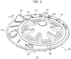
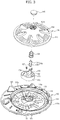
- FIGS. 2 and 3 are assembled and exploded perspective views illustrating a pulsator device 100 according to an embodiment.
- FIG. 4 is a sectional view taken along line I-I of FIG. 2 .
- the pulsator device 100 includes a first pulsator 110, a second pulsator 130, and a shaft 150.
- At least part of the first pulsator 110 is disposed in the rotary tub 30.
- the pulsator 110 is rotatably mounted at the bottom of the rotary tub 30.
- the first pulsator 110 has a shaft coupling part 112 formed at the center thereof.
- the drive shaft 78 is coupled to the shaft coupling part 112.
- the drive shaft 78 serves as a rotary shaft of the first pulsator 110.
- the first pulsator 110 is rotated about the drive shaft 78.
- a recess 114 is formed at the upper part of the first pulsator 110.
- a side wall 115 is formed around the recess 114.
- the recess 114 may be disposed such that the recess 114 deviates to one side of the first pulsator 110 in the radial direction thereof.
- the shaft 150 is connected to the first pulsator 110 such that the shaft 150 is rotated with the first pulsator 110.
- the shaft 150 may be connected to the first pulsator 110 via a connector 170.
- the shaft 150 may be directly coupled to the first pulsator 110 without an additional part to connect the shaft 150 and the first pulsator 110.
- a connector coupling part 116 connected to the connector 170 is provided in the recess 114 of the first pulsator 110.
- the connector coupling part 116 has a guide rib 117 protruding upward from the bottom of the recess 114.
- the guide rib 117 serves to guide the coupling position of the connector and to stably support the inside of the connector 170 in a state in which the connector 170 is coupled.
- the shaft coupling part 112 is disposed inside the guide rib 117.
- the shaft coupling part 112 is connected to the guide rib 117 by reinforcement ribs 118.
- One or more coupling bosses 119 are provided at the connector coupling part 116.
- a coupling hole 119a is formed at each of the coupling bosses 119.
- a through hole 112a coupling the connector 170 and the drive shaft 78 may be formed at the top of the shaft coupling part 112.
- the connector 170 is disposed between the first pulsator 110 and the second pulsator 130.
- the connector 170 is coupled to the first pulsator 110 such that the connector 170 is rotated with the first pulsator 110.
- the connector 170 is fixed to the first pulsator 110 by a coupling member such as a bolt.
- the connector 170 has coupling holes 172 and 174 corresponding respectively to the coupling holes 119a of the connector coupling part 116 and the through hole 112a of the shaft coupling part 112.
- the connector 170, the first pulsator 110 and the drive shaft 78 are coupled using a single coupling member inserted through the coupling hole 174 of the connector 170 and the through hole 112a of the shaft coupling part 112, secure coupling of the respective components 170, 110 and 78 is achieved while the number of coupling points is reduced.
- FIG. 5 is a front view illustrating the connector of the pulsator device according to the embodiment of the present invention.
- FIG. 6 is a sectional view illustrating the second pulsator and the connector of the pulsator device according to the embodiment.
- FIG. 7 is a sectional view illustrating the first pulsator of the pulsator device according to the embodiment.
- the shaft 150 is eccentric with respect to the drive shaft 78.
- the shaft 150 turns around an axis X of the drive shaft 78 during the rotation of the first pulsator 110.
- the shaft 150 may be inclined with respect to the drive shaft 78.
- the second pulsator 130 coupled to the shaft 150 is inclined with respect to the horizontal direction, with the result that an arbitrary point of the second pulsator 130 moves up and down during the rotation of the first pulsator 110.
- the shaft 150 may be disposed such that the shaft 150 is inclined upward toward the outside of the first pulsator 110 in the radial direction thereof.
- the shaft 150 may be disposed such that the shaft 150 is inclined upward toward the inside of the first pulsator 110 in the radial direction thereof, i.e., toward the drive shaft 78.
- the shaft 150 is disposed such that the shaft 150 is inclined upward toward the outside of the first pulsator 110 in the radial direction thereof so as to increase the distance between the center O of the second pulsator 130 and the axis X of the drive shaft 78, i.e., a turn radius r (see FIG. 8 ) of the second pulsator 130.
- the shaft 150 may be integrated with the connector 170.
- the connector 170 has an inclined surface 176 disposed at a position where the connector 170 deviates from the drive shaft 78 to one side and inclined with respect to the horizontal direction.
- the inclined surface 176 may be inclined downward by a predetermined angle ⁇ along a direction in which the inclined surface 176 is distant from the drive shaft 78.
- the connector 170 may be disposed at a position where the connector 170 deviates from the drive shaft 78 to one side, and the shaft 150 may be vertically formed, such that the second pulsator 130 is horizontally disposed. That is, the angle of the inclined surface of the connector 170 coupled to the second pulsator 130 may be set to 0 such that second pulsator 130 is horizontally disposed.
- the shaft 150 extends upward from the inclined surface 176 of the connector 170.
- the shaft 150 may extend from the inclined surface 176 such that the shaft 150 is perpendicular to the inclined surface 176. Therefore, the shaft 150 is disposed such that the shaft 150 is eccentric with respect to the drive shaft 78 and is inclined upward in the direction in which the shaft 150 is distant from the drive shaft 78.
- the second pulsator 130 is rotatably coupled to the shaft 150.
- the second pulsator 130 is not constrained by the shaft 150 such that the second pulsator 130 and the shaft 150 are rotated relative to each other.
- the coupling boss 132 is supported at the inclined surface 176 of the connector 170.
- a bearing 134 may be disposed between the inside of the shaft coupling hole 133 and the shaft 150 such that the second pulsator 130 is smoothly rotated relative to the shaft 150.
- a bearing housing 138 may be fixed inside the shaft coupling hole 133, and the bearing 134 may be fixed to the inside of the bearing housing 138.
- the bearing 134 may be an oilless bearing.
- the bearing 134 may include an upper bearing 135 fixed to the upper part of the bearing housing 138 and a lower bearing 136 fixed to the lower part of the bearing housing 138.
- the lower bearing 136 has a flange 137 disposed between the bottom of the coupling boss 132 and the inclined surface 176 of the connector. The coupling boss 132 of the second pulsator 130 is smoothly rotated on the inclined surface 176 of the connector 170 by the flange 137.
- a cap receiving part 132a is provided at the top of the coupling boss 132 of the second pulsator 130.
- a cap 140 may be mounted at the cap receiving part 132a.
- the second pulsator 130 is disposed in the recess 114 formed at the first pulsator 110 such that the recess 114 is inclined with respect to the horizontal direction.
- An example in which the second pulsator 130 is inclined by an angle ⁇ with respect to a horizontal direction H is illustrated in FIG. 6 .
- the angle ⁇ by which the second pulsator 130 is inclined with respect to the horizontal direction decides a range of up and down movement of the second pulsator 130.
- the angle ⁇ When the angle ⁇ is large, the second pulsator 130 generates a strong up and down stream of water.
- the angle ⁇ When the angle ⁇ is too large, however, laundry may deviate to one side of the rotary tub 30 during washing. Therefore, the angle ⁇ may be 10 degrees or less.
- the angle ⁇ may be 3 degrees or more.
- first pulsator and the second pulsator may be disposed parallel to each other by disposing the first pulsator and the second pulsator such that the first pulsator and the second pulsator are inclined with respect to the horizontal direction and providing the first pulsator and the second pulsator with the same inclination angle.
- the second pulsator may be horizontally disposed irrespective of the inclination of the first pulsator.
- the first pulsator may be horizontally disposed irrespective of the inclination of the second pulsator.
- an upper end 115a of the side wall 115 of the first pulsator 110 extends such that the upper end 115a is inclined with respect to the horizontal direction in correspondence to the inclination of the second pulsator 130.
- a portion 131a, adjacent to the upper end 115a of the side wall 115, of the top 131 of second pulsator 130 is formed so as to be smoothly connected to the upper end 115a of the side wall 115.
- the portion 131a of the second pulsator 130 may be connected to the upper end 115a of the side wall without a large step although the portion 131a of the second pulsator 130 is located higher or lower than the upper end 115a of the side wall. Also, the portion 131a of the second pulsator 130 may be disposed in substantially the same plane as the upper end 115a of the side wall. The top of the second pulsator 130 corresponding to the top of the first pulsator 110 may be disposed approximately 2 mm lower than the top of the first pulsator 110. In this structure, laundry or foreign matter may be prevented from being caught between the side wall 115 of the first pulsator 110 and the second pulsator 130.
- the side wall 115 of the first pulsator 110 has a step forming part 115b extending toward the inside of the first pulsator 110 in the radial direction thereof.
- the second pulsator 130 has ribs 143 and 144 protruding from the outer edge thereof toward the step forming part 115b.
- the step forming part 115b and the ribs 143 and 144 further prevent laundry or foreign matter from being caught between the side wall 115 of the first pulsator 110 and the second pulsator 130.
- the step forming part 115b and the ribs 143 and 144 prevent the foreign matter from being introduced to the lower part of the second pulsator 130.
- the ribs may include a first rib 143 disposed adjacent to the side wall 115 of the first pulsator 110 and a second rib 144 disposed inside the first rib 143 while being spaced apart from the first rib 143 by a predetermined distance.
- a protrusion 115c may be formed at the side wall 115 of the first pulsator 110.
- the protrusion 115c is disposed adjacent to the first rib 143 or the second rib 144 of the second pulsator 130 and protrudes toward the second pulsator 130.
- the protrusion 115c may protrude between the first rib 143 and the second rib 144 of the second pulsator 130.
- the second pulsator 130 has through holes 146 for wash water circulation. Wash water adjacent to the second pulsator 130 may be introduced to the lower part of the second pulsator 130 through the through holes 146.
- the second pulsator 130 has blades 148 protruding from the top thereof.
- the blades 148 are disposed in the circumferential direction of the second pulsator 130.
- the blades 148 rub against laundry such that the laundry hinders the second pulsator 130 from rotating (rotating about the shaft 150).
- Water stream forming blades 120 are disposed in the circumferential direction of the first pulsator 110. Each of the water stream forming blades 120 protrudes from the top 110a of the first pulsator 110 and extends from the outside of the recess 114 in the radial direction thereof. The water stream forming blades 120 generate a rotating stream of water during the rotation of the first pulsator 110.
- Holes 122 are disposed at the recess 114 of the first pulsator 110 in the circumferential direction thereof.
- a plurality of pumping blades 124 are radially disposed at the rear of the first pulsator 110.
- wash water adjacent to the first pulsator 110 is introduced toward the rear of the first pulsator 110 through the holes 122 of the first pulsator 110, and is pushed to the outside of the first pulsator 110 in the radial direction thereof by the pumping blades 124.
- the wash water, pushed by the pumping blades 124 is guided to the pumping duct 36 (see FIG. 1 ) through a flow channel (not shown) formed at the lower part of the rotary tub 30, and is discharged into the rotary tub 30 through the discharge ports 37 of the pumping duct 36.
- FIG. 8 is a view illustrating the operation of the pulsator device in the washing machine according to the embodiment.
- wash water is supplied into the rotary tub 30 through the water supply pipe 52.
- the motor 72 is operated to drive the pulsator device 100.
- Power from the motor 72 rotates the first pulsator 110 through the drive shaft 78.
- a rotating stream of water is generated by the water stream forming blades 120 disposed at the top of the first pulsator 110.
- the shaft 150 connected to the first pulsator 110 via the connector 170 turns around the axis X of the drive shaft 78.
- the shaft 150 is rotated relative to the second pulsator 130, and an arbitrary point at the top of the second pulsator 130 moves up and down to generate a stream of water.
- the second pulsator 130 turns around the drive shaft 78 with a radius r corresponding to the distance between the center O of the second pulsator 130 and the axis X of the drive shaft 78 during the rotation of the first pulsator 110 to generate an up and down stream of water as shown in FIG. 6 .
- the pulsator device 100 generates a composite stream of water through the rotating movement of the first pulsator 110, the up and down movement of the second pulsator 130, and the turning movement of the second pulsator 130, thereby effectively washing laundry using a small amount of water and preventing the laundry from being damaged by a strong stream of water.
- laundry is effectively washed using a small amount of water using the pulsator device that generates a composite stream of water, and the laundry is prevented from being damaged by a strong stream of water.
- the laundry is prevented from being caught in the pulsator device and thus being damaged during washing.
- the laundry may turn upside down in the rotary tub by the rotating movement of the first pulsator, the up and down movement of the second pulsator, and the turning movement of the second pulsator.
Landscapes
- Engineering & Computer Science (AREA)
- Textile Engineering (AREA)
- Accessory Of Washing/Drying Machine, Commercial Washing/Drying Machine, Other Washing/Drying Machine (AREA)
- Main Body Construction Of Washing Machines And Laundry Dryers (AREA)
Description
- Embodiments relate to a washing machine having a pulsator device that generates a composite stream of water.
- Generally, a washing machine adopting a pulsator washes laundry using a stream of water generated by the rotation of the pulsator.
- The pulsator may generate a strong stream of water to improve washing force of the washing machine. However, when the stream of water is too strong, laundry may be damaged.
- The performance of the washing machine is basically decided according to the washing force of the washing machine. If the laundry is damaged during washing, however, the washing machine may not provide users with a good impression although the washing force of the washing machine is excellent.
- Meanwhile, an amount of water used to wash laundry is also critical to decide the performance of the washing machine. When an amount of water used to wash the laundry is increased, water supply time and drainage time increase, and therefore, total washing time increases, which is not economical.
-
US 5 921 114 A discloses a washing machine with a pulsator. This pulsator comprises a number of washing blades and there is a cover member with spout fans arranged therein. The pulsator is rotated by a corresponding driving axis and shaft combiner and the driving axis is driven by a driving motor via a pulley and a belt. A driving gear is rotated together with a main body or pulsator and is in engagement with pinions which are connected to a thin shaft of corresponding spout fan. By rotation of those spout fans water is expelled through corresponding scheduling water stream holes and spout outlet. -
US 20037154749 A1 discloses a washing machine. Two different devices are used, namely rotary blade and wobbling device. Corresponding rotary blade is installed under a washboard and is used to generate forced water currents which are guided to an upper portion of the spin-drying tub through a corresponding water current guide. Such rotary blade is not a pulsator but something like a pump used for transferring the water to an upper portion of the tub. -
US 2004/031294 A1 discloses a washing machine with only one pulsator in the form of a converting unit with wash blade and corresponding blades. -
US 5 950 460 A discloses a washing machine with an agitator which comprises a number of different means like washing shaft, driving wheel, four driven wheels, stirring blades, and washing bar with swing blades formed on its periphery. -
GB 2 315 782 A -
CN 201 258 400 Y discloses a pulsator device with a first pulsator and a number of second pulsators with an arrangement of the rotary shaft and other shafts. There are recesses in the first pulsator in which the second pulsators are introduced, which are then rotated by corresponding gears. -
KR 2003 0040661 A - It is an object to provide a pulsator device that generates a composite stream of water to improve performance of a washing machine.
- This object is solved by the features of
claim 1. Advantageous embodiments are disclosed by the subclaims. - The first pulsator may have a recess formed at an upper part thereof, and the second pulsator may be disposed in the recess.
- The shaft may be disposed such that the shaft is inclined upward toward an outside of the first pulsator in a radial direction thereof.
- The pulsator device may further include a connector disposed between the first pulsator and the second pulsator, the connector being fixed to the first pulsator such that the connector is rotated with the first pulsator, wherein the connector may have an inclined surface disposed at a position where the connector deviates from the rotary shaft to one side and inclined with respect to a horizontal direction, and the shaft may extend perpendicularly from the inclined surface.
- The recess may be disposed such that the recess deviates to one side of the first pulsator in a radial direction thereof.
- The first pulsator may have a side wall to form the recess, and the side wall may have an upper end extending such that the upper end is inclined with respect to a horizontal direction.
- The second pulsator may have at least one rib protruding downward from an outer edge thereof.
- The side wall may have a step forming part extending toward an inside of the first pulsator in a radial direction thereof.
- The at least one rib may include a first rib disposed adjacent to the side wall of the first pulsator and a second rib disposed inside the first rib.
- The second pulsator may be inclined with respect to a horizontal direction by an angle of 3 to 10 degrees.
- The first pulsator may have at least one water stream forming blade extending from an outside of the recess in a radial direction thereof.
- A corresponding washing machine includes a tub, a rotary tub rotatably disposed in the tub, the first pulsator coupled to a drive shaft, at least part of the first pulsator being rotatably disposed in the rotary tub, the shaft connected to the first pulsator such that the shaft is rotated with the first pulsator, the shaft being inclined with respect to the drive shaft, and the second pulsator rotatably coupled to the shaft, the second pulsator being disposed at a top of the first pulsator, wherein the second pulsator is inclined with respect to a horizontal direction.
- The top of the first pulsator may extend such that the top of the first pulsator is inclined with respect to the horizontal direction in correspondence to the inclination of the second pulsator.
- The first pulsator may have a recess formed at an upper part thereof and a side wall formed around the recess, and the second pulsator may be disposed in the recess.
- The shaft is eccentric with respect to the drive shaft such that the shaft turns around the drive shaft during rotation of the first pulsator.
- An upper end of the side wall of the first pulsator and a top of the second pulsator may be connected to each other in substantially the same plane.
- The washing machine may further include a connector disposed between the first pulsator and the second pulsator, the connector being fixed to the first pulsator such that the connector is rotated with the first pulsator, wherein the connector may have an inclined surface disposed at a position where the connector deviates from the drive shaft to one side and inclined with respect to a horizontal direction, and the shaft may extend upward from the inclined surface.
- In accordance with another aspect, a washing machine includes a tub, a rotary tub rotatably disposed in the tub, a first pulsator configured such that at least part of the first pulsator is rotatably disposed in the rotary tub, the first pulsator having a recess eccentric to one side in a radial direction thereof, a shaft disposed at the first pulsator such that the shaft is rotated with the first pulsator, and a second pulsator rotatably coupled to the shaft, the second pulsator being disposed in the recess of the first pulsator.
- In accordance with another aspect, a washing machine includes a tub, a rotary tub rotatably disposed in the tub, a first pulsator configured such that at least part of the first pulsator is rotatably disposed in the rotary tub, the first pulsator having a top inclined with respect to a horizontal direction, a shaft disposed at the top of the first pulsator, and a second pulsator rotatably coupled to the shaft, the second pulsator being disposed in parallel to the inclined top of the first pulsator.
- The shaft is disposed at a position eccentric from a center of rotation of the first pulsator.
- The shaft may have an inclined surface formed at a bottom thereof to support the second pulsator, and the inclined surface may have substantially the same angle as the inclined top of the first pulsator.
- A corresponding washing machine includes the first pulsator configured to be rotated about a rotary shaft, the shaft connected to the first pulsator such that the shaft is rotated with the first pulsator, and the second pulsator rotatably coupled to the shaft, the second pulsator having a smaller diameter than the first pulsator, wherein the first pulsator has an outer top formed at an outside of the second pulsator in a radial direction thereof, and the first pulsator is provided at the outer top thereof with a water stream forming blade to generate a rotating stream of water. The second pulsator may have a top, and the second pulsator may be provided at the top thereof with at least one blade.
- The second pulsator may be inclined with respect to a horizontal direction, and the outer top of the first pulsator may be inclined with respect to the horizontal direction.
- The shaft is eccentric with respect to the rotary shaft.
- The shaft may be coupled to the second pulsator such that the shaft is perpendicular to the inclined top of the second pulsator.
- The second pulsator may be provided at the top thereof with through holes for wash water circulation.
- The first pulsator includes a plurality of water stream forming blades, and at least one of the water stream forming blades may be larger than the others.
- These and/or other aspects will become apparent and more readily appreciated from the following description of the embodiments, taken in conjunction with the accompanying drawings of which:
-
FIG. 1 is a view illustrating a washing machine according to an embodiment; -
FIGS. 2 and3 are assembled and exploded perspective views illustrating a pulsator device according to an embodiment; -
FIG. 4 is a sectional view taken along line I-I ofFIG. 2 ; -
FIG. 5 is a front view illustrating a connector of the pulsator device according to the embodiment; -
FIG. 6 is a sectional view illustrating a second pulsator and the connector of the pulsator device according to the embodiment; -
FIG. 7 is a sectional view illustrating a first pulsator of the pulsator device according to the embodiment; and -
FIG. 8 is a view illustrating the operation of the pulsator device in the washing machine according to the embodiment. - Reference will now be made in detail to the embodiments, examples of which are illustrated in the accompanying drawings, wherein like reference numerals refer to like elements throughout.
-
FIG. 1 is a view illustrating awashing machine 1 according to an embodiment. As shown inFIG. 1 , thewashing machine 1 includes acabinet 10 constituting the external appearance of thewashing machine 1, a tub 20 disposed in thecabinet 10, arotary tub 30 rotatably disposed in the tub 20, and apulsator device 100 disposed in therotary tub 30 to generate a stream of water. - At the top of the
cabinet 10 is formed anintroduction port 11 through which laundry is introduced into therotary tub 30. Theintroduction port 11 is opened and closed by adoor 12 mounted at the top of thecabinet 10. - The tub 20 is supported at the
cabinet 10 by asuspension device 40 to connect the outer lower side of the tub 20 and the inner upper side of thecabinet 10. - Above the tub 20 is mounted a
water supply pipe 52 to supply wash water into the tub 20. One side of thewater supply pipe 52 is connected to an external water supply source (not shown), and the other side of thewater supply pipe 52 is connected to adetergent supply device 54. Water supplied through thewater supply pipe 52 passes through thedetergent supply device 54 such that the water is supplied into the tub 20 together with a detergent. - Below the tub 20 is mounted a
drainage device 60 to discharge wash water from the tub 20 out of thewashing machine 1. Thedrainage device 60 may include adrainage pipe 62 connected to the bottom of the tub 20 and adrainage valve 64 mounted on thedrainage pipe 62. In thedrainage pipe 62 may be mounted a drainage pump (not shown) to forcibly discharge wash water from the tub 20. - The
rotary tub 30 is configured in the form of a cylinder open at the top thereof. A plurality of spin-dryingholes 32 are formed at the circumference of therotary tub 30. At the top of therotary tub 30 may be mounted abalancer 34 by which therotary tub 30 is kept stable during high speed rotation. Inside therotary tub 30 is mounted a pumpingduct 36 to circulate wash water in therotary tub 30. The pumpingduct 36 hasdischarge ports 37 to discharge wash water. - Below the tub 20 is mounted a
drive device 70. Thedrive device 70 includes amotor 72, apower transmission device 74, a clutch 76, and adrive shaft 78. Thedrive shaft 78 is coupled to thepulsator device 100 to transmit power from themotor 72 to thepulsator device 100. - Power from the
motor 72 is transmitted to the clutch 76 via thepower transmission device 74. Thepower transmission device 74 may includepulleys 74a and abelt 74b connecting thepulleys 74a. The clutch 76 intermits power from themotor 72 such that therotary tub 30 and thepulsator device 100 are rotated together or thepulsator device 100 is rotated while therotary tub 30 is stopped. -
FIGS. 2 and3 are assembled and exploded perspective views illustrating apulsator device 100 according to an embodiment.FIG. 4 is a sectional view taken along line I-I ofFIG. 2 . - As shown in
FIGS. 1 to 4 , thepulsator device 100 includes afirst pulsator 110, asecond pulsator 130, and ashaft 150. - At least part of the
first pulsator 110 is disposed in therotary tub 30. Thepulsator 110 is rotatably mounted at the bottom of therotary tub 30. Thefirst pulsator 110 has ashaft coupling part 112 formed at the center thereof. Thedrive shaft 78 is coupled to theshaft coupling part 112. - The
drive shaft 78 serves as a rotary shaft of thefirst pulsator 110. When power from themotor 72 is transmitted to thedrive shaft 78 via the clutch 76, thefirst pulsator 110 is rotated about thedrive shaft 78. - A
recess 114 is formed at the upper part of thefirst pulsator 110. Aside wall 115 is formed around therecess 114. Therecess 114 may be disposed such that therecess 114 deviates to one side of thefirst pulsator 110 in the radial direction thereof. - The
shaft 150 is connected to thefirst pulsator 110 such that theshaft 150 is rotated with thefirst pulsator 110. Theshaft 150 may be connected to thefirst pulsator 110 via aconnector 170. Alternatively, theshaft 150 may be directly coupled to thefirst pulsator 110 without an additional part to connect theshaft 150 and thefirst pulsator 110. - A
connector coupling part 116 connected to theconnector 170 is provided in therecess 114 of thefirst pulsator 110. Theconnector coupling part 116 has aguide rib 117 protruding upward from the bottom of therecess 114. Theguide rib 117 serves to guide the coupling position of the connector and to stably support the inside of theconnector 170 in a state in which theconnector 170 is coupled. - The
shaft coupling part 112 is disposed inside theguide rib 117. Theshaft coupling part 112 is connected to theguide rib 117 byreinforcement ribs 118. - One or
more coupling bosses 119 are provided at theconnector coupling part 116. Acoupling hole 119a is formed at each of thecoupling bosses 119. Meanwhile, a throughhole 112a coupling theconnector 170 and thedrive shaft 78 may be formed at the top of theshaft coupling part 112. - The
connector 170 is disposed between thefirst pulsator 110 and thesecond pulsator 130. Theconnector 170 is coupled to thefirst pulsator 110 such that theconnector 170 is rotated with thefirst pulsator 110. Theconnector 170 is fixed to thefirst pulsator 110 by a coupling member such as a bolt. To this end, theconnector 170 hascoupling holes coupling holes 119a of theconnector coupling part 116 and the throughhole 112a of theshaft coupling part 112. - When the
connector 170, thefirst pulsator 110 and thedrive shaft 78 are coupled using a single coupling member inserted through thecoupling hole 174 of theconnector 170 and the throughhole 112a of theshaft coupling part 112, secure coupling of therespective components -
FIG. 5 is a front view illustrating the connector of the pulsator device according to the embodiment of the present invention.FIG. 6 is a sectional view illustrating the second pulsator and the connector of the pulsator device according to the embodiment.FIG. 7 is a sectional view illustrating the first pulsator of the pulsator device according to the embodiment. - As shown in
FIGS. 3 to 7 , theshaft 150 is eccentric with respect to thedrive shaft 78. In this structure, theshaft 150 turns around an axis X of thedrive shaft 78 during the rotation of thefirst pulsator 110. - Also, the
shaft 150 may be inclined with respect to thedrive shaft 78. In this case, thesecond pulsator 130 coupled to theshaft 150 is inclined with respect to the horizontal direction, with the result that an arbitrary point of thesecond pulsator 130 moves up and down during the rotation of thefirst pulsator 110. - The
shaft 150 may be disposed such that theshaft 150 is inclined upward toward the outside of thefirst pulsator 110 in the radial direction thereof. Alternatively, theshaft 150 may be disposed such that theshaft 150 is inclined upward toward the inside of thefirst pulsator 110 in the radial direction thereof, i.e., toward thedrive shaft 78. However, theshaft 150 is disposed such that theshaft 150 is inclined upward toward the outside of thefirst pulsator 110 in the radial direction thereof so as to increase the distance between the center O of thesecond pulsator 130 and the axis X of thedrive shaft 78, i.e., a turn radius r (seeFIG. 8 ) of thesecond pulsator 130. - The
shaft 150 may be integrated with theconnector 170. As shown in
FIGS. 5 and6 , theconnector 170 has aninclined surface 176 disposed at a position where theconnector 170 deviates from thedrive shaft 78 to one side and inclined with respect to the horizontal direction. Theinclined surface 176 may be inclined downward by a predetermined angle θ along a direction in which theinclined surface 176 is distant from thedrive shaft 78. - Meanwhile, the
connector 170 may be disposed at a position where theconnector 170 deviates from thedrive shaft 78 to one side, and theshaft 150 may be vertically formed, such that thesecond pulsator 130 is horizontally disposed. That is, the angle of the inclined surface of theconnector 170 coupled to thesecond pulsator 130 may be set to 0 such thatsecond pulsator 130 is horizontally disposed. - The
shaft 150 extends upward from theinclined surface 176 of theconnector 170. Theshaft 150 may extend from theinclined surface 176 such that theshaft 150 is perpendicular to theinclined surface 176. Therefore, theshaft 150 is disposed such that theshaft 150 is eccentric with respect to thedrive shaft 78 and is inclined upward in the direction in which theshaft 150 is distant from thedrive shaft 78. - The
second pulsator 130 is rotatably coupled to theshaft 150. Thesecond pulsator 130 is not constrained by theshaft 150 such that thesecond pulsator 130 and theshaft 150 are rotated relative to each other. - A
coupling boss 132 having a shaft coupling hole 133, through which theshaft 150 is inserted, is disposed at the center of thesecond pulsator 130. Thecoupling boss 132 is supported at theinclined surface 176 of theconnector 170. - A bearing 134 may be disposed between the inside of the shaft coupling hole 133 and the
shaft 150 such that thesecond pulsator 130 is smoothly rotated relative to theshaft 150. A bearinghousing 138 may be fixed inside the shaft coupling hole 133, and thebearing 134 may be fixed to the inside of the bearinghousing 138. Thebearing 134 may be an oilless bearing. - The
bearing 134 may include anupper bearing 135 fixed to the upper part of the bearinghousing 138 and alower bearing 136 fixed to the lower part of the bearinghousing 138. When thebearing 134 is constituted by two parts as described above, ease of assembly and assembly accuracy of thebearing 134 are improved. Thelower bearing 136 has aflange 137 disposed between the bottom of thecoupling boss 132 and theinclined surface 176 of the connector. Thecoupling boss 132 of thesecond pulsator 130 is smoothly rotated on theinclined surface 176 of theconnector 170 by theflange 137. - Meanwhile, a
cap receiving part 132a is provided at the top of thecoupling boss 132 of thesecond pulsator 130. Acap 140 may be mounted at thecap receiving part 132a. - The
second pulsator 130 is disposed in therecess 114 formed at thefirst pulsator 110 such that therecess 114 is inclined with respect to the horizontal direction. An example in which thesecond pulsator 130 is inclined by an angle θ with respect to a horizontal direction H is illustrated inFIG. 6 . - When the
second pulsator 130 is disposed in an inclined state, an arbitrary point of the top of thesecond pulsator 130 moves up and down during the rotation of thefirst pulsator 110. This movement of thesecond pulsator 130 generates an up and down stream of water in therotary tub 30. - The angle θ by which the
second pulsator 130 is inclined with respect to the horizontal direction decides a range of up and down movement of thesecond pulsator 130. When the angle θ is large, thesecond pulsator 130 generates a strong up and down stream of water. When the angle θ is too large, however, laundry may deviate to one side of therotary tub 30 during washing. Therefore, the angle θ may be 10 degrees or less. On the other hand, when the angle θ is too small, the up and down movement of thesecond pulsator 130 is slight, with the result that an up and down stream of water is not effectively generated. Therefore, the angle θ may be 3 degrees or more. - In another embodiment, the first pulsator and the second pulsator may be disposed parallel to each other by disposing the first pulsator and the second pulsator such that the first pulsator and the second pulsator are inclined with respect to the horizontal direction and providing the first pulsator and the second pulsator with the same inclination angle.
- However, the second pulsator may be horizontally disposed irrespective of the inclination of the first pulsator. Also, the first pulsator may be horizontally disposed irrespective of the inclination of the second pulsator.
- As shown in
FIGS. 4 and7 , anupper end 115a of theside wall 115 of thefirst pulsator 110 extends such that theupper end 115a is inclined with respect to the horizontal direction in correspondence to the inclination of thesecond pulsator 130. Aportion 131a, adjacent to theupper end 115a of theside wall 115, of the top 131 ofsecond pulsator 130 is formed so as to be smoothly connected to theupper end 115a of theside wall 115. - That is, the
portion 131a of thesecond pulsator 130 may be connected to theupper end 115a of the side wall without a large step although theportion 131a of thesecond pulsator 130 is located higher or lower than theupper end 115a of the side wall. Also, theportion 131a of thesecond pulsator 130 may be disposed in substantially the same plane as theupper end 115a of the side wall. The top of thesecond pulsator 130 corresponding to the top of thefirst pulsator 110 may be disposed approximately 2 mm lower than the top of thefirst pulsator 110. In this structure, laundry or foreign matter may be prevented from being caught between theside wall 115 of thefirst pulsator 110 and thesecond pulsator 130. - The
side wall 115 of thefirst pulsator 110 has astep forming part 115b extending toward the inside of thefirst pulsator 110 in the radial direction thereof. Thesecond pulsator 130 hasribs step forming part 115b. Thestep forming part 115b and theribs side wall 115 of thefirst pulsator 110 and thesecond pulsator 130. Although foreign matter is caught between theside wall 115 of thefirst pulsator 110 and thesecond pulsator 130, thestep forming part 115b and theribs second pulsator 130. - The ribs may include a
first rib 143 disposed adjacent to theside wall 115 of thefirst pulsator 110 and asecond rib 144 disposed inside thefirst rib 143 while being spaced apart from thefirst rib 143 by a predetermined distance. - To further improve such a function to prevent the introduction of foreign matter, a
protrusion 115c may be formed at theside wall 115 of thefirst pulsator 110. Theprotrusion 115c is disposed adjacent to thefirst rib 143 or thesecond rib 144 of thesecond pulsator 130 and protrudes toward thesecond pulsator 130. Theprotrusion 115c may protrude between thefirst rib 143 and thesecond rib 144 of thesecond pulsator 130. - As shown in
FIGS. 2 and3 , thesecond pulsator 130 has throughholes 146 for wash water circulation. Wash water adjacent to thesecond pulsator 130 may be introduced to the lower part of thesecond pulsator 130 through the throughholes 146. - Also, the
second pulsator 130 hasblades 148 protruding from the top thereof. Theblades 148 are disposed in the circumferential direction of thesecond pulsator 130. Theblades 148 rub against laundry such that the laundry hinders thesecond pulsator 130 from rotating (rotating about the shaft 150). - Water
stream forming blades 120 are disposed in the circumferential direction of thefirst pulsator 110. Each of the waterstream forming blades 120 protrudes from the top 110a of thefirst pulsator 110 and extends from the outside of therecess 114 in the radial direction thereof. The waterstream forming blades 120 generate a rotating stream of water during the rotation of thefirst pulsator 110. -
Holes 122 are disposed at therecess 114 of thefirst pulsator 110 in the circumferential direction thereof. A plurality ofpumping blades 124 are radially disposed at the rear of thefirst pulsator 110. During washing of laundry, wash water adjacent to thefirst pulsator 110 is introduced toward the rear of thefirst pulsator 110 through theholes 122 of thefirst pulsator 110, and is pushed to the outside of thefirst pulsator 110 in the radial direction thereof by thepumping blades 124. The wash water, pushed by thepumping blades 124, is guided to the pumping duct 36 (seeFIG. 1 ) through a flow channel (not shown) formed at the lower part of therotary tub 30, and is discharged into therotary tub 30 through thedischarge ports 37 of the pumpingduct 36. - Hereinafter, the operation of the washing machine according to the embodiment will be described with reference to
FIGS. 1 and6 to 8 .FIG. 8 is a view illustrating the operation of the pulsator device in the washing machine according to the embodiment. - When a user puts laundry into the
rotary tub 30, puts a detergent into thedetergent supply device 54, and operates thewashing machine 1, wash water is supplied into therotary tub 30 through thewater supply pipe 52. When the water supply operation is completed, themotor 72 is operated to drive thepulsator device 100. - Power from the
motor 72 rotates thefirst pulsator 110 through thedrive shaft 78. When thefirst pulsator 110 is rotated, a rotating stream of water is generated by the waterstream forming blades 120 disposed at the top of thefirst pulsator 110. - Since the
second pulsator 130 is disposed on thefirst pulsator 110 in an inclined state, an arbitrary point at the top of thesecond pulsator 130 moves up and down during the rotation of thefirst pulsator 110, with the result that an up and down stream of water is generated in therotary tub 30. - That is, when the
first pulsator 110 is rotated, theshaft 150 connected to thefirst pulsator 110 via theconnector 170 turns around the axis X of thedrive shaft 78. At this time, when the weight of the laundry in therotary tub 30 is applied to thesecond pulsator 130, and therefore, the rotation of thesecond pulsator 130 is restricted, theshaft 150 is rotated relative to thesecond pulsator 130, and an arbitrary point at the top of thesecond pulsator 130 moves up and down to generate a stream of water. - Since the
shaft 150 is rotated relative to thesecond pulsator 130 when a load of the laundry is applied to thesecond pulsator 130, the load applied to thesecond pulsator 130 is not transmitted to themotor 72. Consequently, a load of themotor 72 is reduced. - Meanwhile, since the center O of the
second pulsator 130 is eccentric with respect to thedrive shaft 78, as shown inFIG. 8 , thesecond pulsator 130 turns around thedrive shaft 78 with a radius r corresponding to the distance between the center O of thesecond pulsator 130 and the axis X of thedrive shaft 78 during the rotation of thefirst pulsator 110 to generate an up and down stream of water as shown inFIG. 6 . - In this way, the
pulsator device 100 according to the embodiment generates a composite stream of water through the rotating movement of thefirst pulsator 110, the up and down movement of thesecond pulsator 130, and the turning movement of thesecond pulsator 130, thereby effectively washing laundry using a small amount of water and preventing the laundry from being damaged by a strong stream of water. - As is apparent from the above description, laundry is effectively washed using a small amount of water using the pulsator device that generates a composite stream of water, and the laundry is prevented from being damaged by a strong stream of water.
- Also, the laundry is prevented from being caught in the pulsator device and thus being damaged during washing.
- Also, the laundry may turn upside down in the rotary tub by the rotating movement of the first pulsator, the up and down movement of the second pulsator, and the turning movement of the second pulsator.
- Although a few embodiments have been shown and described, it would be appreciated by those skilled in the art that changes may be made in these embodiments without departing from the principles of the invention, the scope of which is defined in the claims.
Claims (14)
- A pulsator device (100) usable with a washing machine (1), comprising:a first pulsator (110) configured to be rotated about a rotary shaft (78); whereby the pulsator device further comprises a shaft (150) connected to the first pulsator (110) such that the shaft (150) is rotated together with the first pulsator (110), the shaft (150) being eccentric with respect to the rotary shaft (78), anda second pulsator (130) coupled to the shaft (150), wherein the first pulsator (110) includes water stream forming blades (120) disposed in the circumferential direction of the first pulsator (110), and the second pulsator (130) includes blades (148) protruding from the top of the second pulsator (130) characterized in that the second pulsator (130) is rotatably coupled to the shaft and the shaft (150) is inclined with respect to the rotary shaft (78).
- The pulsator device according to claim 1, wherein
the first pulsator (110) has a recess (114) formed at an upper part thereof, and
the second pulsator (130) is disposed in the recess (114). - The pulsator device according to claims 1 or 2, wherein the shaft (150) is disposed such that the shaft is inclined upward toward an outside of the first pulsator (110) in a radial direction thereof.
- The pulsator device according to any one of the preceding claims, further comprising:a connector (170) disposed between the first pulsator (110) and the second pulsator (130), the connector being fixed to the first pulsator such that the connector is rotated with the first pulsator, whereinthe connector (170) has an inclined surface (176) disposed at a position where the shaft is provided by the connector and inclined with respect to a horizontal direction (H), andthe shaft (150) extends perpendicularly from the inclined surface (176).
- The pulsator device according to claim 2, wherein the recess (114) is disposed such that the recess deviates to one side of the first pulsator (110) in a radial direction thereof.
- The pulsator device according to claim 2, wherein
the first pulsator (110) has a side wall (115) to form the recess (114), and
the side wall (115) has an upper end (115a) extending such that the upper end is inclined with respect to a horizontal direction. - The pulsator device according to claim 6, wherein
the second pulsator (130) has at least one rib (143,144) protruding downward from an outer edge thereof, and
the side wall (115) has a step forming part (115b) extending toward an inside of the first pulsator in a radial direction thereof. - The pulsator device according to claim 1, wherein the second pulsator (130) is inclined with respect to a horizontal direction by an angle of 3 to 10 degrees.
- The pulsator device according to claim 2, wherein the water stream forming blades (120) extend from an outside of the recess (114) in a radial direction thereof.
- The pulsator device according to claim 9, wherein
at least one of the plurality of water stream forming blades is larger than the others. - The pulsator device according to claim 1, wherein
the second pulsator (130) is inclined with respect to a horizontal direction (H), and
the first pulsator (110) has a top extending such that the top of the first pulsator is inclined with respect to the horizontal direction in correspondence to the inclination of the second pulsator. - The pulsator device according to claim 11, wherein
the first pulsator (110) has a recess (114) formed at the top thereof and a side wall (115) formed around the recess,
the second pulsator (130) is disposed in the recess (114), and
an upper end (115a) of the side wall (115) of the first pulsator and a top of the second pulsator (130) are connected to each other in substantially the same plane. - The pulsator device according to claim 1, wherein
the first pulsator (110) has a top inclined with respect to a horizontal direction, and
the second pulsator (130) is disposed in parallel to the inclined top of the first pulsator (110). - A washing machine (1) comprising the pulsator device (100) according to any one of the preceding claims.
Applications Claiming Priority (1)
| Application Number | Priority Date | Filing Date | Title |
|---|---|---|---|
| KR1020090100644A KR101462171B1 (en) | 2009-10-22 | 2009-10-22 | Pulsator device for washing machine and washing machine having same |
Publications (2)
| Publication Number | Publication Date |
|---|---|
| EP2314747A1 EP2314747A1 (en) | 2011-04-27 |
| EP2314747B1 true EP2314747B1 (en) | 2019-08-21 |
Family
ID=43413594
Family Applications (1)
| Application Number | Title | Priority Date | Filing Date |
|---|---|---|---|
| EP10176726.7A Not-in-force EP2314747B1 (en) | 2009-10-22 | 2010-09-15 | Pulsator device usable with washing machine and washing machine having the same |
Country Status (6)
| Country | Link |
|---|---|
| US (1) | US9464374B2 (en) |
| EP (1) | EP2314747B1 (en) |
| KR (1) | KR101462171B1 (en) |
| CN (1) | CN102041651B (en) |
| ES (1) | ES2752748T3 (en) |
| RU (1) | RU2471024C2 (en) |
Families Citing this family (11)
| Publication number | Priority date | Publication date | Assignee | Title |
|---|---|---|---|---|
| KR101716822B1 (en) | 2010-06-07 | 2017-03-16 | 삼성전자주식회사 | Pulsator device usable with washing maine and washing machine having the same |
| US20150059415A1 (en) * | 2013-08-30 | 2015-03-05 | Jared Greiman | Washing machine with agitator |
| JP2016002184A (en) * | 2014-06-16 | 2016-01-12 | ハイアールアジア株式会社 | Washing machine |
| KR102244839B1 (en) * | 2014-08-01 | 2021-04-26 | 엘지전자 주식회사 | Apparatus for treating laundry |
| KR102560457B1 (en) * | 2015-10-08 | 2023-07-27 | 엘지전자 주식회사 | Washing machine |
| KR20170087737A (en) * | 2016-01-21 | 2017-07-31 | 엘지전자 주식회사 | Laundry Treating Apparatus |
| KR20170087675A (en) | 2016-01-21 | 2017-07-31 | 엘지전자 주식회사 | Laundry Treating Apparatus |
| KR20170087676A (en) * | 2016-01-21 | 2017-07-31 | 엘지전자 주식회사 | Laundry Treating Apparatus |
| KR102434445B1 (en) * | 2017-08-18 | 2022-08-22 | 삼성전자주식회사 | Pulsator apparatus for washing machine and Washing machine having the same |
| CN114232271B (en) * | 2021-12-22 | 2023-12-19 | 宁波金帅集团有限公司 | Mounting device for mounting pulsator shaft of washing machine |
| CN114934369B (en) * | 2022-06-30 | 2024-07-05 | 海信冰箱有限公司 | Washing machine |
Citations (3)
| Publication number | Priority date | Publication date | Assignee | Title |
|---|---|---|---|---|
| GB2315782A (en) * | 1996-07-31 | 1998-02-11 | Daewoo Electronics Co Ltd | Clothes washer having a pulsator apparatus |
| KR20030040661A (en) * | 2001-11-15 | 2003-05-23 | 엘지전자 주식회사 | Pulsator of washing machine |
| CN201258400Y (en) * | 2008-08-26 | 2009-06-17 | 松下电化住宅设备机器(杭州)有限公司 | Dual dynamic wave wheel |
Family Cites Families (39)
| Publication number | Priority date | Publication date | Assignee | Title |
|---|---|---|---|---|
| US2071622A (en) * | 1931-05-08 | 1937-02-23 | C E Butler | Washing machine |
| US2105218A (en) * | 1932-10-29 | 1938-01-11 | Apex Electrical Mfg Co | Laundry machine |
| US2192758A (en) * | 1936-10-24 | 1940-03-05 | Gen Electric | Washing machine |
| US2186786A (en) * | 1937-02-17 | 1940-01-09 | Electric Household Utilities | Washing machine |
| US3952557A (en) | 1974-06-20 | 1976-04-27 | General Electric Company | Wobble washing machine |
| US4068503A (en) | 1975-07-14 | 1978-01-17 | Whirlpool Corporation | Combined oscillating and unidirectional agitator for automatic washer |
| JPS5778893A (en) * | 1980-10-31 | 1982-05-17 | Tokyo Shibaura Electric Co | Washing machine doubling as hydroextracting |
| US4329859A (en) | 1980-11-03 | 1982-05-18 | General Electric Company | Basket mounting arrangement for a washing machine |
| US4440004A (en) | 1981-07-31 | 1984-04-03 | General Electric Company | Wobble washer |
| US4423526A (en) * | 1982-04-21 | 1984-01-03 | Plastic Oddities, Inc. | Resilient gasket between toilet bowl and drainpipe |
| JPS6290196A (en) * | 1985-10-17 | 1987-04-24 | 松下電器産業株式会社 | centrifugal washing machine |
| CN2140909Y (en) | 1992-12-08 | 1993-08-25 | 舒勇 | Impeller of washing machine |
| US5460018A (en) | 1994-02-22 | 1995-10-24 | Whirlpool Corporation | Vertical axis washer |
| US5596891A (en) * | 1994-09-15 | 1997-01-28 | Samsung Electronics Co., Ltd. | Apparatus for untwisting clothes in an automatic washer |
| KR200156821Y1 (en) * | 1995-05-16 | 1999-09-01 | 구자홍 | Washing wing of washing machine |
| KR100192610B1 (en) * | 1995-06-26 | 1999-06-15 | 전주범 | washer |
| KR200149201Y1 (en) * | 1996-04-29 | 1999-06-15 | 전주범 | Rotational wing of a washing machine |
| US5791167A (en) * | 1996-05-23 | 1998-08-11 | Whirlpool Corporation | Automatic washer and a wash plate clothes deflector therefor |
| KR100207362B1 (en) | 1996-10-31 | 1999-07-15 | 전주범 | Stirring device of the washing machine |
| JPH10127972A (en) * | 1996-10-31 | 1998-05-19 | Sharp Corp | Electric washing machine |
| JP2919830B2 (en) * | 1997-04-17 | 1999-07-19 | 三星電子株式会社 | Pulsator for washing machine |
| KR19980085150A (en) | 1997-05-28 | 1998-12-05 | 배순훈 | Stirring device of the washing machine |
| TW405001B (en) * | 1998-01-31 | 2000-09-11 | Samsung Electronics Co Ltd | Washing maching having a water guide for forming vertical and horizontal currents of wash water |
| WO2000006819A1 (en) * | 1998-07-29 | 2000-02-10 | Sharp Kabushiki Kaisha | Pulsator system for electric washing machines |
| JP2000157775A (en) * | 1998-11-30 | 2000-06-13 | Toshiba Corp | Washing machine |
| US6115863A (en) * | 1999-03-08 | 2000-09-12 | Whirlpool Corporation | Drive system for a vertical axis washer |
| WO2003029547A1 (en) | 2001-09-28 | 2003-04-10 | Delphi Technologies, Inc. | Wobble joint |
| CN1268801C (en) * | 2001-12-24 | 2006-08-09 | 三星电子株式会社 | Washing machine |
| KR100444956B1 (en) | 2002-02-15 | 2004-08-21 | 삼성전자주식회사 | Washing Machine |
| KR100451858B1 (en) | 2002-05-17 | 2004-10-08 | 엘지전자 주식회사 | Washer |
| KR100480715B1 (en) * | 2002-08-13 | 2005-04-06 | 엘지전자 주식회사 | Washing Machine |
| KR100459139B1 (en) | 2002-10-21 | 2004-12-03 | 엘지전자 주식회사 | Washer |
| KR100493308B1 (en) | 2002-12-27 | 2005-06-07 | 엘지전자 주식회사 | Washer |
| US6865912B2 (en) * | 2002-12-27 | 2005-03-15 | Lg Electronics Inc. | Washing machine |
| KR100493307B1 (en) | 2002-12-27 | 2005-06-07 | 엘지전자 주식회사 | Washer |
| KR100461872B1 (en) | 2003-02-06 | 2004-12-18 | 삼성전자주식회사 | Washing Machine |
| KR100997145B1 (en) * | 2003-07-19 | 2010-11-30 | 삼성전자주식회사 | Drum Washing Machine with Rotatable Pulsator |
| KR101275128B1 (en) * | 2006-06-30 | 2013-06-14 | 동부대우전자 주식회사 | Washing machine comprising pulsator |
| CN201254654Y (en) * | 2008-09-02 | 2009-06-10 | 王建华 | Double-impeller double-driving washing machine |
-
2009
- 2009-10-22 KR KR1020090100644A patent/KR101462171B1/en active Active
-
2010
- 2010-08-31 US US12/923,075 patent/US9464374B2/en active Active
- 2010-09-15 ES ES10176726T patent/ES2752748T3/en active Active
- 2010-09-15 EP EP10176726.7A patent/EP2314747B1/en not_active Not-in-force
- 2010-09-28 CN CN201010501319.4A patent/CN102041651B/en active Active
- 2010-09-29 RU RU2010140034/12A patent/RU2471024C2/en active
Patent Citations (3)
| Publication number | Priority date | Publication date | Assignee | Title |
|---|---|---|---|---|
| GB2315782A (en) * | 1996-07-31 | 1998-02-11 | Daewoo Electronics Co Ltd | Clothes washer having a pulsator apparatus |
| KR20030040661A (en) * | 2001-11-15 | 2003-05-23 | 엘지전자 주식회사 | Pulsator of washing machine |
| CN201258400Y (en) * | 2008-08-26 | 2009-06-17 | 松下电化住宅设备机器(杭州)有限公司 | Dual dynamic wave wheel |
Non-Patent Citations (1)
| Title |
|---|
| DATABASE WPI Week 200360, Derwent World Patents Index; AN 2003-633826 * |
Also Published As
| Publication number | Publication date |
|---|---|
| US20110094271A1 (en) | 2011-04-28 |
| CN102041651B (en) | 2015-11-25 |
| KR101462171B1 (en) | 2014-11-21 |
| ES2752748T3 (en) | 2020-04-06 |
| KR20110043906A (en) | 2011-04-28 |
| US9464374B2 (en) | 2016-10-11 |
| RU2010140034A (en) | 2012-04-10 |
| RU2471024C2 (en) | 2012-12-27 |
| EP2314747A1 (en) | 2011-04-27 |
| CN102041651A (en) | 2011-05-04 |
Similar Documents
| Publication | Publication Date | Title |
|---|---|---|
| US9464374B2 (en) | Pulsator device usable with washing machine and washing machine having the same | |
| US9194071B2 (en) | Pulsator device for washing machines and washing machine having the same | |
| CN101994230B (en) | Washing machine, connection of inner tub of washing machine and balancer, and assembling method thereof | |
| US8801118B2 (en) | Knob assembly and washing machine having the same | |
| US20130276483A1 (en) | Washing machine | |
| CN103132278B (en) | Washing machine | |
| US9284676B2 (en) | Drum type washing machine | |
| EP3792386B1 (en) | Washing machine | |
| EP3342917B1 (en) | Laundry machine | |
| KR20110057302A (en) | Fluid balancer and washing machine with it | |
| US12241196B2 (en) | Washing machine | |
| CN108350639A (en) | Washing machine | |
| JP6591156B2 (en) | Washing machine | |
| US20200190719A1 (en) | Pulsator device for washing machine and washing machine including same | |
| US11624425B2 (en) | Laundry treatment apparatus | |
| KR100459139B1 (en) | Washer | |
| KR102541695B1 (en) | Washing machine |
Legal Events
| Date | Code | Title | Description |
|---|---|---|---|
| PUAI | Public reference made under article 153(3) epc to a published international application that has entered the european phase |
Free format text: ORIGINAL CODE: 0009012 |
|
| AK | Designated contracting states |
Kind code of ref document: A1 Designated state(s): AL AT BE BG CH CY CZ DE DK EE ES FI FR GB GR HR HU IE IS IT LI LT LU LV MC MK MT NL NO PL PT RO SE SI SK SM TR |
|
| AX | Request for extension of the european patent |
Extension state: BA ME RS |
|
| 17P | Request for examination filed |
Effective date: 20111027 |
|
| RAP1 | Party data changed (applicant data changed or rights of an application transferred) |
Owner name: SAMSUNG ELECTRONICS CO., LTD. |
|
| STAA | Information on the status of an ep patent application or granted ep patent |
Free format text: STATUS: EXAMINATION IS IN PROGRESS |
|
| 17Q | First examination report despatched |
Effective date: 20170908 |
|
| GRAP | Despatch of communication of intention to grant a patent |
Free format text: ORIGINAL CODE: EPIDOSNIGR1 |
|
| STAA | Information on the status of an ep patent application or granted ep patent |
Free format text: STATUS: GRANT OF PATENT IS INTENDED |
|
| INTG | Intention to grant announced |
Effective date: 20190328 |
|
| GRAS | Grant fee paid |
Free format text: ORIGINAL CODE: EPIDOSNIGR3 |
|
| GRAA | (expected) grant |
Free format text: ORIGINAL CODE: 0009210 |
|
| STAA | Information on the status of an ep patent application or granted ep patent |
Free format text: STATUS: THE PATENT HAS BEEN GRANTED |
|
| AK | Designated contracting states |
Kind code of ref document: B1 Designated state(s): AL AT BE BG CH CY CZ DE DK EE ES FI FR GB GR HR HU IE IS IT LI LT LU LV MC MK MT NL NO PL PT RO SE SI SK SM TR |
|
| REG | Reference to a national code |
Ref country code: GB Ref legal event code: FG4D |
|
| REG | Reference to a national code |
Ref country code: CH Ref legal event code: EP |
|
| REG | Reference to a national code |
Ref country code: DE Ref legal event code: R096 Ref document number: 602010060633 Country of ref document: DE |
|
| REG | Reference to a national code |
Ref country code: AT Ref legal event code: REF Ref document number: 1169886 Country of ref document: AT Kind code of ref document: T Effective date: 20190915 |
|
| REG | Reference to a national code |
Ref country code: IE Ref legal event code: FG4D |
|
| REG | Reference to a national code |
Ref country code: LT Ref legal event code: MG4D |
|
| REG | Reference to a national code |
Ref country code: NL Ref legal event code: MP Effective date: 20190821 |
|
| PG25 | Lapsed in a contracting state [announced via postgrant information from national office to epo] |
Ref country code: NL Free format text: LAPSE BECAUSE OF FAILURE TO SUBMIT A TRANSLATION OF THE DESCRIPTION OR TO PAY THE FEE WITHIN THE PRESCRIBED TIME-LIMIT Effective date: 20190821 Ref country code: SE Free format text: LAPSE BECAUSE OF FAILURE TO SUBMIT A TRANSLATION OF THE DESCRIPTION OR TO PAY THE FEE WITHIN THE PRESCRIBED TIME-LIMIT Effective date: 20190821 Ref country code: LT Free format text: LAPSE BECAUSE OF FAILURE TO SUBMIT A TRANSLATION OF THE DESCRIPTION OR TO PAY THE FEE WITHIN THE PRESCRIBED TIME-LIMIT Effective date: 20190821 Ref country code: BG Free format text: LAPSE BECAUSE OF FAILURE TO SUBMIT A TRANSLATION OF THE DESCRIPTION OR TO PAY THE FEE WITHIN THE PRESCRIBED TIME-LIMIT Effective date: 20191121 Ref country code: NO Free format text: LAPSE BECAUSE OF FAILURE TO SUBMIT A TRANSLATION OF THE DESCRIPTION OR TO PAY THE FEE WITHIN THE PRESCRIBED TIME-LIMIT Effective date: 20191121 Ref country code: FI Free format text: LAPSE BECAUSE OF FAILURE TO SUBMIT A TRANSLATION OF THE DESCRIPTION OR TO PAY THE FEE WITHIN THE PRESCRIBED TIME-LIMIT Effective date: 20190821 Ref country code: HR Free format text: LAPSE BECAUSE OF FAILURE TO SUBMIT A TRANSLATION OF THE DESCRIPTION OR TO PAY THE FEE WITHIN THE PRESCRIBED TIME-LIMIT Effective date: 20190821 Ref country code: PT Free format text: LAPSE BECAUSE OF FAILURE TO SUBMIT A TRANSLATION OF THE DESCRIPTION OR TO PAY THE FEE WITHIN THE PRESCRIBED TIME-LIMIT Effective date: 20191223 |
|
| PG25 | Lapsed in a contracting state [announced via postgrant information from national office to epo] |
Ref country code: LV Free format text: LAPSE BECAUSE OF FAILURE TO SUBMIT A TRANSLATION OF THE DESCRIPTION OR TO PAY THE FEE WITHIN THE PRESCRIBED TIME-LIMIT Effective date: 20190821 Ref country code: IS Free format text: LAPSE BECAUSE OF FAILURE TO SUBMIT A TRANSLATION OF THE DESCRIPTION OR TO PAY THE FEE WITHIN THE PRESCRIBED TIME-LIMIT Effective date: 20191221 Ref country code: AL Free format text: LAPSE BECAUSE OF FAILURE TO SUBMIT A TRANSLATION OF THE DESCRIPTION OR TO PAY THE FEE WITHIN THE PRESCRIBED TIME-LIMIT Effective date: 20190821 Ref country code: GR Free format text: LAPSE BECAUSE OF FAILURE TO SUBMIT A TRANSLATION OF THE DESCRIPTION OR TO PAY THE FEE WITHIN THE PRESCRIBED TIME-LIMIT Effective date: 20191122 |
|
| REG | Reference to a national code |
Ref country code: AT Ref legal event code: MK05 Ref document number: 1169886 Country of ref document: AT Kind code of ref document: T Effective date: 20190821 |
|
| PG25 | Lapsed in a contracting state [announced via postgrant information from national office to epo] |
Ref country code: TR Free format text: LAPSE BECAUSE OF FAILURE TO SUBMIT A TRANSLATION OF THE DESCRIPTION OR TO PAY THE FEE WITHIN THE PRESCRIBED TIME-LIMIT Effective date: 20190821 |
|
| REG | Reference to a national code |
Ref country code: DE Ref legal event code: R119 Ref document number: 602010060633 Country of ref document: DE |
|
| REG | Reference to a national code |
Ref country code: ES Ref legal event code: FG2A Ref document number: 2752748 Country of ref document: ES Kind code of ref document: T3 Effective date: 20200406 |
|
| PG25 | Lapsed in a contracting state [announced via postgrant information from national office to epo] |
Ref country code: AT Free format text: LAPSE BECAUSE OF FAILURE TO SUBMIT A TRANSLATION OF THE DESCRIPTION OR TO PAY THE FEE WITHIN THE PRESCRIBED TIME-LIMIT Effective date: 20190821 Ref country code: DK Free format text: LAPSE BECAUSE OF FAILURE TO SUBMIT A TRANSLATION OF THE DESCRIPTION OR TO PAY THE FEE WITHIN THE PRESCRIBED TIME-LIMIT Effective date: 20190821 Ref country code: PL Free format text: LAPSE BECAUSE OF FAILURE TO SUBMIT A TRANSLATION OF THE DESCRIPTION OR TO PAY THE FEE WITHIN THE PRESCRIBED TIME-LIMIT Effective date: 20190821 Ref country code: EE Free format text: LAPSE BECAUSE OF FAILURE TO SUBMIT A TRANSLATION OF THE DESCRIPTION OR TO PAY THE FEE WITHIN THE PRESCRIBED TIME-LIMIT Effective date: 20190821 Ref country code: RO Free format text: LAPSE BECAUSE OF FAILURE TO SUBMIT A TRANSLATION OF THE DESCRIPTION OR TO PAY THE FEE WITHIN THE PRESCRIBED TIME-LIMIT Effective date: 20190821 |
|
| PG25 | Lapsed in a contracting state [announced via postgrant information from national office to epo] |
Ref country code: IS Free format text: LAPSE BECAUSE OF FAILURE TO SUBMIT A TRANSLATION OF THE DESCRIPTION OR TO PAY THE FEE WITHIN THE PRESCRIBED TIME-LIMIT Effective date: 20200224 Ref country code: CZ Free format text: LAPSE BECAUSE OF FAILURE TO SUBMIT A TRANSLATION OF THE DESCRIPTION OR TO PAY THE FEE WITHIN THE PRESCRIBED TIME-LIMIT Effective date: 20190821 Ref country code: SK Free format text: LAPSE BECAUSE OF FAILURE TO SUBMIT A TRANSLATION OF THE DESCRIPTION OR TO PAY THE FEE WITHIN THE PRESCRIBED TIME-LIMIT Effective date: 20190821 Ref country code: MC Free format text: LAPSE BECAUSE OF FAILURE TO SUBMIT A TRANSLATION OF THE DESCRIPTION OR TO PAY THE FEE WITHIN THE PRESCRIBED TIME-LIMIT Effective date: 20190821 Ref country code: SM Free format text: LAPSE BECAUSE OF FAILURE TO SUBMIT A TRANSLATION OF THE DESCRIPTION OR TO PAY THE FEE WITHIN THE PRESCRIBED TIME-LIMIT Effective date: 20190821 |
|
| REG | Reference to a national code |
Ref country code: CH Ref legal event code: PL |
|
| PLBE | No opposition filed within time limit |
Free format text: ORIGINAL CODE: 0009261 |
|
| STAA | Information on the status of an ep patent application or granted ep patent |
Free format text: STATUS: NO OPPOSITION FILED WITHIN TIME LIMIT |
|
| PG2D | Information on lapse in contracting state deleted |
Ref country code: IS |
|
| PG25 | Lapsed in a contracting state [announced via postgrant information from national office to epo] |
Ref country code: LU Free format text: LAPSE BECAUSE OF NON-PAYMENT OF DUE FEES Effective date: 20190915 Ref country code: IE Free format text: LAPSE BECAUSE OF NON-PAYMENT OF DUE FEES Effective date: 20190915 Ref country code: CH Free format text: LAPSE BECAUSE OF NON-PAYMENT OF DUE FEES Effective date: 20190930 Ref country code: DE Free format text: LAPSE BECAUSE OF NON-PAYMENT OF DUE FEES Effective date: 20200401 Ref country code: LI Free format text: LAPSE BECAUSE OF NON-PAYMENT OF DUE FEES Effective date: 20190930 |
|
| REG | Reference to a national code |
Ref country code: BE Ref legal event code: MM Effective date: 20190930 |
|
| 26N | No opposition filed |
Effective date: 20200603 |
|
| PG25 | Lapsed in a contracting state [announced via postgrant information from national office to epo] |
Ref country code: SI Free format text: LAPSE BECAUSE OF FAILURE TO SUBMIT A TRANSLATION OF THE DESCRIPTION OR TO PAY THE FEE WITHIN THE PRESCRIBED TIME-LIMIT Effective date: 20190821 Ref country code: BE Free format text: LAPSE BECAUSE OF NON-PAYMENT OF DUE FEES Effective date: 20190930 |
|
| GBPC | Gb: european patent ceased through non-payment of renewal fee |
Effective date: 20191121 |
|
| PG25 | Lapsed in a contracting state [announced via postgrant information from national office to epo] |
Ref country code: FR Free format text: LAPSE BECAUSE OF NON-PAYMENT OF DUE FEES Effective date: 20191021 Ref country code: GB Free format text: LAPSE BECAUSE OF NON-PAYMENT OF DUE FEES Effective date: 20191121 |
|
| PGFP | Annual fee paid to national office [announced via postgrant information from national office to epo] |
Ref country code: ES Payment date: 20201008 Year of fee payment: 11 |
|
| PG25 | Lapsed in a contracting state [announced via postgrant information from national office to epo] |
Ref country code: CY Free format text: LAPSE BECAUSE OF FAILURE TO SUBMIT A TRANSLATION OF THE DESCRIPTION OR TO PAY THE FEE WITHIN THE PRESCRIBED TIME-LIMIT Effective date: 20190821 |
|
| PG25 | Lapsed in a contracting state [announced via postgrant information from national office to epo] |
Ref country code: MT Free format text: LAPSE BECAUSE OF FAILURE TO SUBMIT A TRANSLATION OF THE DESCRIPTION OR TO PAY THE FEE WITHIN THE PRESCRIBED TIME-LIMIT Effective date: 20190821 Ref country code: HU Free format text: LAPSE BECAUSE OF FAILURE TO SUBMIT A TRANSLATION OF THE DESCRIPTION OR TO PAY THE FEE WITHIN THE PRESCRIBED TIME-LIMIT; INVALID AB INITIO Effective date: 20100915 |
|
| PGFP | Annual fee paid to national office [announced via postgrant information from national office to epo] |
Ref country code: IT Payment date: 20210914 Year of fee payment: 12 |
|
| PG25 | Lapsed in a contracting state [announced via postgrant information from national office to epo] |
Ref country code: MK Free format text: LAPSE BECAUSE OF FAILURE TO SUBMIT A TRANSLATION OF THE DESCRIPTION OR TO PAY THE FEE WITHIN THE PRESCRIBED TIME-LIMIT Effective date: 20190821 |
|
| REG | Reference to a national code |
Ref country code: ES Ref legal event code: FD2A Effective date: 20221102 |
|
| PG25 | Lapsed in a contracting state [announced via postgrant information from national office to epo] |
Ref country code: ES Free format text: LAPSE BECAUSE OF NON-PAYMENT OF DUE FEES Effective date: 20210916 |
|
| PG25 | Lapsed in a contracting state [announced via postgrant information from national office to epo] |
Ref country code: IT Free format text: LAPSE BECAUSE OF NON-PAYMENT OF DUE FEES Effective date: 20220915 |