EP2314425A2 - Robot system and workpiece picking method - Google Patents
Robot system and workpiece picking method Download PDFInfo
- Publication number
- EP2314425A2 EP2314425A2 EP10185324A EP10185324A EP2314425A2 EP 2314425 A2 EP2314425 A2 EP 2314425A2 EP 10185324 A EP10185324 A EP 10185324A EP 10185324 A EP10185324 A EP 10185324A EP 2314425 A2 EP2314425 A2 EP 2314425A2
- Authority
- EP
- European Patent Office
- Prior art keywords
- workpiece
- robot
- bin
- disturbing
- workpieces
- Prior art date
- Legal status (The legal status is an assumption and is not a legal conclusion. Google has not performed a legal analysis and makes no representation as to the accuracy of the status listed.)
- Withdrawn
Links
Images




Classifications
-
- B—PERFORMING OPERATIONS; TRANSPORTING
- B25—HAND TOOLS; PORTABLE POWER-DRIVEN TOOLS; MANIPULATORS
- B25J—MANIPULATORS; CHAMBERS PROVIDED WITH MANIPULATION DEVICES
- B25J9/00—Program-controlled manipulators
- B25J9/16—Program controls
- B25J9/1694—Program controls characterised by use of sensors other than normal servo-feedback from position, speed or acceleration sensors, perception control, multi-sensor controlled systems, sensor fusion
- B25J9/1697—Vision controlled systems
-
- B—PERFORMING OPERATIONS; TRANSPORTING
- B25—HAND TOOLS; PORTABLE POWER-DRIVEN TOOLS; MANIPULATORS
- B25J—MANIPULATORS; CHAMBERS PROVIDED WITH MANIPULATION DEVICES
- B25J9/00—Program-controlled manipulators
- B25J9/16—Program controls
- B25J9/1679—Program controls characterised by the tasks executed
- B25J9/1687—Assembly, peg and hole, palletising, straight line, weaving pattern movement
-
- G—PHYSICS
- G05—CONTROLLING; REGULATING
- G05B—CONTROL OR REGULATING SYSTEMS IN GENERAL; FUNCTIONAL ELEMENTS OF SUCH SYSTEMS; MONITORING OR TESTING ARRANGEMENTS FOR SUCH SYSTEMS OR ELEMENTS
- G05B2219/00—Program-control systems
- G05B2219/30—Nc systems
- G05B2219/37—Measurements
- G05B2219/37555—Camera detects orientation, position workpiece, points of workpiece
-
- G—PHYSICS
- G05—CONTROLLING; REGULATING
- G05B—CONTROL OR REGULATING SYSTEMS IN GENERAL; FUNCTIONAL ELEMENTS OF SUCH SYSTEMS; MONITORING OR TESTING ARRANGEMENTS FOR SUCH SYSTEMS OR ELEMENTS
- G05B2219/00—Program-control systems
- G05B2219/30—Nc systems
- G05B2219/40—Robotics, robotics mapping to robotics vision
- G05B2219/40053—Pick 3-D object from pile of objects
-
- G—PHYSICS
- G05—CONTROLLING; REGULATING
- G05B—CONTROL OR REGULATING SYSTEMS IN GENERAL; FUNCTIONAL ELEMENTS OF SUCH SYSTEMS; MONITORING OR TESTING ARRANGEMENTS FOR SUCH SYSTEMS OR ELEMENTS
- G05B2219/00—Program-control systems
- G05B2219/30—Nc systems
- G05B2219/40—Robotics, robotics mapping to robotics vision
- G05B2219/40564—Recognize shape, contour of object, extract position and orientation
Definitions
- the present invention relates to robot systems and workpiece picking methods.
- bin-picking techniques have been proposed in recent years.
- workpieces such as bolts
- An example of such a technique is disclosed in Japanese Patent Laid-Open Publication No. 2009-128201 .
- information about three-dimensional positions and orientations (three-dimensional information) within a bin is obtained before a grasping operation.
- a portion of a workpiece, the portion being to be grasped by a handling device is determined in advance On the basis of the obtained three-dimensional information, a workpiece to be grasped is detected and a handling operation is performed.
- workpieces are randomly placed in the bin, they may overlap one another in a complex way. In such a case, for example, when a portion to be grasped is buried under other workpieces in the bin, there may be no workpiece that can be properly grasped in the handling operation.
- An object of the present invention is to provide a robot system and a workpiece picking method that can minimize the possibility of erroneous handling and are capable of accurately picking workpieces from a bin.
- shape information about a plurality of workpieces in a bin is detected by a shape sensor; the presence or absence of a graspable workpiece is detected on the basis of a result of detection performed by the shape sensor; if no graspable workpiece is detected, a robot is caused to disturb a distribution of the workpieces in the bin; and if a graspable workpiece is detected, the robot is caused to grasp the detected workpiece.
- a workpiece picking system (robot system) 100 includes a robot 101, a bin 102, a sensor unit (shape sensor) 103, a robot control device 104, and a conveying belt 105.
- the robot 101 grasps workpieces W in the bin 102 one by one and moves them to a transport rack 105A on the conveying belt 105.
- the conveying belt 105 is driven toward the next process and conveys the transport rack 105A thereon.
- the transport rack 105A is a container that contains workpieces W.
- the transport rack 105A is made of resin or the like.
- the workpieces W may be directly placed on the conveying belt 105, without using the transport rack 105A.
- each workpiece W has a wide head portion W1 and an arm portion (rod-like portion) W2 extending from the head portion W1.
- the head portion W1 has a through hole (circular through hole) W3.
- the robot 101 is a so-called articulated robot that is secured at its base to a fixed surface and has an arm extending from the base to the distal end.
- the arm of the robot 101 has a plurality of rotary joints, which are driven by a servomotor incorporated in the arm. Each of the joints is driven under the control of the robot control device 104. Note that in Fig. 2 , the shape of the robot 101 is depicted schematically.
- a grasping device (grasper) 10 is attached to the distal end of the arm of the robot 101.
- the grasping device 10 has a pair of fingers 10A that are opened and closed, that is, moved away from and close to each other by an actuator. This opening and closing of the fingers 10A is also controlled by the robot control device 104.
- the grasping device 10 may be any device capable of grasping or holding a workpiece W.
- Examples of the grasping device 10 include a gripper having fingers that swing to hold a workpiece W, and a suction device that uses air or electromagnetic force.
- the bin 102 is a box made of, for example, reinforced resin or metal.
- a plurality of workpieces W i.e., objects to be detected are placed randomly (in bulk) in the bin 102
- the sensor unit 103 includes a camera 1 and a laser scanner (distance sensor) 2.
- the sensor unit 103 is disposed above the bin 102 (see Fig. 1 ) with the camera 1 and the laser scanner 2 oriented downward.
- the laser scanner 2 illuminates a mirror with laser slit light while causing a motor to rotate the mirror.
- the laser scanner 2 thus illuminates objects with the laser slit light over a large area.
- a housing 103A of the sensor unit 103 includes a sensor controller having a memory device and a computing device.
- the camera 1 and the laser scanner 2 operate under the control of the sensor controller.
- An image (pixel arrangement data) detected from above the bin 102 by the sensor unit 103 and distance information on the image are input to the robot control device 104, which is connected to the sensor controller.
- An operation command from the robot control device 104 is input to the sensor controller.
- the robot control device 104 is a computer that includes a memory device, an electronic calculator, and an input device.
- the robot control device 104 is connected to the robot 101 and the grasping device 10 such that they can communicate with each other.
- Fig. 1 illustrates a functional configuration of the robot control device 104.
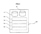
- the robot control device 104 includes a workpiece shape memory 11, a grasping information memory 12, a target workpiece detector 13, a grasping operation controller 14, a disturbing operation controller 15, and a robot controller 16.
- the workpiece shape memory 11 stores three-dimensional shape data of workpieces W measured in advance.
- the three-dimensional shape data stored in the workpiece shape memory 11 varies depending on the type of workpiece W.
- the grasping information memory 12 stores grasping operation information including grasping position information and grasping method information.
- the grasping position information indicates which portion of a workpiece W is to be grasped by the grasping device 10 when the workpiece W is properly grasped.
- the grasping method information indicates how the workpiece W is to be grasped by the grasping device 10.
- the through hole W3 of a workpiece W is stored as the grasping position information.
- Information stored as the grasping method information is a method in which, after the fingers 10A in a closed state are inserted into the through hole W3 of the workpiece W, the fingers 10A are opened (moved apart) to grasp the workpiece W.
- the grasping information memory 12 also stores, in advance, operation information indicating that after the workpiece W is grasped, the robot 101 is operated such that the tip of the arm portion W2 of the grasped workpiece W points downward in the direction of gravity.
- the grasping information memory 12 also stores, in advance, workpiece disturbing operation information for performing a workpiece disturbing operation when no properly graspable workpiece W is detected by using input device of robot control device 104.
- information stored as the workpiece disturbing operation information is information about an operation in which, after the arm portion W2 of a workpiece W is grasped with the fingers 10A, the position of the grasped workpiece W is changed.
- the target workpiece detector 13 detects the orientations of workpieces W in the bin 102, for example, through a matching process using three-dimensional shape information about the workpieces W and detection signals from the sensor unit 103.
- a workpiece W that does not interfere with any other object when the fingers 10A are inserted into the through hole W3 is detected as a target workpiece W.
- the target workpiece W is a workpiece W having an orientation which allows the fingers 10A to grasp it and does not cause interference with any other object.
- a workpiece W on which a workpiece disturbing operation can be performed is detected by the target workpiece detector 13 as a disturbing-operation target workpiece W. Specifically, if the arm portion W2 of a workpiece W is in a graspable state, the target workpiece detector 13 detects the workpiece W as a disturbing-operation target workpiece.
- the grasping operation controller 14 For a workpiece W which is the closest to the grasping device 10 of all target workpieces W detected by the target workpiece detector 13, the grasping operation controller 14 creates a path (corresponding to the operation modes of each servomotor and actuator) for operating the robot 101 and the grasping device 10, on the basis of the grasping operation information described above. The grasping operation controller 14 then sends a command to the robot controller 16.
- the disturbing operation controller 15 creates, for one of disturbing-operation target workpieces W detected by the target workpiece detector 13, a path (corresponding to the operation modes of each servomotor and actuator) for operating the robot 101 and the grasping device 10, on the basis of the workpiece disturbing operation information described above.
- the disturbing operation controller 15 then sends a command to the robot controller 16.
- the robot controller 16 sends an operation signal to each servomotor of the robot 101 and the actuator of the grasping device 10 to control the operation of the robot 101 and the grasping device 10.
- the robot controller 16 is configured to send an operation signal also to the sensor unit 103.
- the workpiece picking system 100 of the present embodiment is configured as described above. The operation of the workpiece picking system 100 will now be described with reference to Fig. 4 to Fig. 11 .
- the sensor unit 103 operates, in accordance with a command from the robot controller 16, to obtain an image captured from above the bin 102 and distance information on the image.
- a part of every workpiece W in the bin 102 is located near the through hole W3 of another workpiece W and will interfere with the fingers 10A.
- the target workpiece detector 13 detects any of the workpieces W in the bin 102 as a disturbing-operation target workpiece W.
- the robot 101 and the fingers 10A are operated, so that the arm portion W2 of the detected disturbing-operation target workpiece W is pinched and grasped with the fingers 10A.
- the robot 101 is caused to lift the workpiece W, with the arm portion W2 grasped by the fingers 10A.
- the fingers 10A are opened to release the grasped workpiece W.
- the workpiece W is thrown from the fingers 10A to the bin 102 as illustrated in Fig. 7 (workpiece disturbing operation).
- the sensor unit 103 is operated again to obtain an image captured from above the bin 102 and distance information on the image.
- a target workpiece W can be detected by the target workpiece detector 13.
- the fingers 10A in a closed state are inserted into the through hole W3 of the target workpiece W as illustrated in Fig. 8 .
- the fingers 10A inserted into the through hole W3 are opened (moved apart) to grasp the workpiece W, which is lifted by the operation of the robot 101.
- the robot 101 is operated such that the tip of the arm portion W2 of the grasped workpiece W points downward in the direction of gravity.
- the different workpiece W can be disengaged from the grasped workpiece W. Therefore, it is possible to prevent that a plurality of workpieces W are picked at the same time.
- the robot 101 After stopping for a predetermined period of time (e.g., one second) in the state of Fig. 10 , the robot 101 operates to transfer the grasped workpiece W toward the transport rack 105A as illustrated in Fig. 11 .
- a predetermined period of time e.g., one second
- the target workpiece detector 13 detects the presence or absence of a workpiece W on which a grasping operation can be performed. If there is no workpiece (target workpiece) W on which a grasping operation can be performed, a grasping operation is not performed. Therefore, it is possible to avoid failure caused by a grasping operation performed even when there is no properly graspable workpiece W.
- the arm portion W2 of any workpiece W detected as a disturbing-operation target workpiece W is grasped and released to disturb the distribution of workpieces W in the bin 102.
- a workpiece W in the bin 102 can be properly grasped.
- the orientation of at least the workpiece W grasped and released by the fingers 10A in the disturbing operation is highly likely to be changed to a graspable orientation. Therefore, as compared to the case where workpieces W in the bin 102 are disturbed by a random operation, the orientation of one or more workpieces W in the bin 102 can be more reliably changed to a graspable orientation by a smaller motion.
- the second embodiment is the same as the first embodiment except that a plurality of different types of workpiece disturbing operations are additionally provided. Components that overlap those of the first embodiment will not be described here, and are given the same reference numerals.
- the grasping information memory 12 stores, in advance, information about a workpiece disturbing operation that grasps and releases the arm portion W2 of a workpiece W (hereinafter referred to as a first disturbing operation) and a condition (workpiece condition) for performing the first disturbing operation.
- the grasping information memory 12 stores, in advance, information about three workpiece disturbing operations (hereinafter referred to as second to fourth disturbing operations) and conditions (workpiece conditions) for performing the respective disturbing operations.
- the second disturbing operation is an operation of grasping and releasing the head portion W1 of a workpiece W with the grasping device 10.
- the workpiece condition for performing the second disturbing operation is that the workpiece W is in an orientation which does not cause interference between any graspable portion of the head portion W1 and either the grasping device 10 or the arm of the robot 101.
- the third disturbing operation is, as illustrated in Fig. 13 , an operation of pulling a workpiece W away from an inner wall 102A of the bin 102.
- the workpiece condition for performing the third disturbing operation is that there is a space between the workpiece W and its surrounding obstacle (which is the inner wall 102A here) for the fingers 10A in a closed state to pass through.
- the fingers 10A enter the bin 102 at an angle from the center of the bin 102 to reach the workpiece W, which is then pulled away from the inner wall 102A.
- the workpiece condition for performing the fourth disturbing operation is that a workpiece W leans against the inner wall 102A of the bin 102 as illustrated in Fig. 14 , or that a distance between the inner wall 102A and the workpiece W is smaller than a predetermined value.
- the fourth disturbing operation is an operation of causing the workpiece W to fall toward the center of the bin 102.
- the fingers 10A are brought into contact with the workpiece W leaning against the inner wall 102A at a position below the center of gravity of the workpiece W, in the direction of arrow P.
- the workpiece W is caused to fall toward the center of the bin 102, for example, by reactive force of the inner wall 102A.
- the order of priority of the disturbing operations is as follows: the first disturbing operation, the second disturbing operation, the third disturbing operation, and the fourth disturbing operation. If it is possible to perform the first disturbing operation, the first disturbing operation is performed. If the condition for performing the first disturbing operation is not satisfied, a determination is made as to whether the condition for performing the second disturbing operation is satisfied. If the condition for performing the second disturbing operation is satisfied, the second disturbing operation is performed. If the condition for performing the second disturbing operation is not satisfied, a determination is made as to whether the condition for performing the third disturbing operation is satisfied. If the condition for performing the third disturbing operation is satisfied, the third disturbing operation is performed. If the condition for performing the third disturbing operation is not satisfied, a determination is made as to whether the condition for performing the fourth disturbing operation is satisfied. If the condition for performing the fourth disturbing operation is satisfied, the fourth disturbing operation is performed. If the condition for performing the fourth disturbing operation is not satisfied, the workpiece picking operation is stopped on the basis of the assumption that there is no graspable workpiece W in the bin 102.
- the workpiece picking system 100 may display an error message on a display of the robot control device 104.
- the workpiece picking system 100 may not be able to accurately handle workpieces
- the workpiece picking system 100 of the second embodiment provides not only the first disturbing operation, but also the second to fourth disturbing operations. Therefore, even if both the grasping operation and the first disturbing operation cannot be performed on any workpiece W, execution of a grasping operation is made possible by performing any of the second to fourth disturbing operations It is thus possible to avoid inconvenience, such as failure in handling workpieces W.
- the arm of the robot 101 or the grasping device 10 may interfere with the inner wall 102A of the bin 102.
- the grasping device 10 is brought close to a workpiece W from an angle which does not cause interference (contact) with the inner wall 102A, and then the grasping device 10 pulls the workpiece W away from the inner wall 102A. Since the workpiece W thus becomes distant from the inner wall 102A, a more reliable workpiece grasping operation can be performed next time.
- the sensor controller 3 in the sensor unit 103 includes a workpiece shape memory 21, a grasping information memory 22, and a target workpiece detector 23.
- the robot control device 104 includes a grasping operation controller 24, a disturbing operation controller 25, and a robot controller 26.
- the sensor controller 3 is connected to an input device, such as an external personal computer (PC).
- PC personal computer
- three-dimensional shape data of workpieces W measured in advance, and grasping operation information including grasping position information and grasping method information are input to the sensor controller 3 and stored in the workpiece shape memory 21 and the grasping information memory 22.
- grasping position information is information about which portion of a workpiece W is to be grasped by the grasping device 10
- grasping method information is information about how the workpiece W is to be grasped by the grasping device 10.
- the target workpiece detector 23 detects the orientations of workpieces W in the bin 102, for example, through a matching process using detection signals from the camera 1 and the laser scanner 2. Then, the target workpiece detector 23 detects a target workpiece W that satisfies a predetermined condition, and sends the position and orientation information about the detected target workpiece W to the robot control device 104.
- the target workpiece detector 23 detects a workpiece W on which a workpiece disturbing operation can be performed as a disturbing-operation target workpiece W. Then, the target workpiece detector 23 sends the position and orientation information about the detected disturbing-operation target workpiece W to the robot control device 104.
- the robot control device 104 illustrated in Fig. 1 is provided as an integral computing device. However, the robot control device 104 may be provided in combination with another computing device as illustrated in Fig. 17 .
- a disturbing-operation target workpiece to be used in a disturbing operation is detected when no graspable workpiece (target workpiece) is detected.
- the mode of disturbing operation may be selected appropriately.
- the grasping device When workpieces and the grasping device are relatively resistant to shocks and if no graspable workpiece (target workpiece) is detected, the grasping device may be inserted into the bin through a predetermined path and may stir the workpieces in the bin. This makes it possible that a disturbing operation be done through a simpler calculation process.
- one of the plurality of workpiece disturbing operations is performed depending on the condition.
- the number of types of workpiece disturbing operations may be either one or more.
- the first disturbing operation involves grasping and releasing the arm portion of a workpiece
- the second workpiece disturbing operation involves grasping and releasing the head portion of a workpiece.
- a distinction may be removed. That is, a workpiece having any graspable portion may be detected as a disturbing-operation target workpiece.
- the shape of workpieces is not limited to that described in the embodiments.
- the present invention can be applied to workpieces of any shape by setting a workpiece disturbing operation appropriate for the shape.
- the shape sensor is disposed near the bin in the embodiments described above, the shape sensor may be mounted on the robot. In this case, the detectable range of the shape sensor can be changed by appropriately operating the robot.
Landscapes
- Engineering & Computer Science (AREA)
- Robotics (AREA)
- Mechanical Engineering (AREA)
- Manipulator (AREA)
Abstract
Description
- The present application claims priority to Japanese Patent Application No.
2009-245091, filed October 26, 2009 2010-027552, filed February 10, 2010 - The present invention relates to robot systems and workpiece picking methods.
- Various bin-picking techniques have been proposed in recent years. In the bin-picking techniques, workpieces, such as bolts, that are identical in shape and are placed randomly (in bulk) in a bin are picked from the bin and handled. An example of such a technique is disclosed in Japanese Patent Laid-Open Publication No.
2009-128201 - In this technique, information about three-dimensional positions and orientations (three-dimensional information) within a bin is obtained before a grasping operation. At the same time, a portion of a workpiece, the portion being to be grasped by a handling device, is determined in advance On the basis of the obtained three-dimensional information, a workpiece to be grasped is detected and a handling operation is performed.
- Since workpieces are randomly placed in the bin, they may overlap one another in a complex way. In such a case, for example, when a portion to be grasped is buried under other workpieces in the bin, there may be no workpiece that can be properly grasped in the handling operation.
- In the related art, however, even if there is actually no workpiece that can be properly grasped, a grasping operation is performed on a workpiece which is most suitable for being grasped. As a result, for example, such a workpiece may be dropped, or more than one workpieces may be erroneously held at the same time. Such erroneous handling may damage the workpieces or a hand of the handling device, and may lead to reduced efficiency of processes involved in handling.
- The present invention has been made in view of the problems associated with the related art described above. An object of the present invention is to provide a robot system and a workpiece picking method that can minimize the possibility of erroneous handling and are capable of accurately picking workpieces from a bin.
- According to one aspect of the present invention, shape information about a plurality of workpieces in a bin is detected by a shape sensor; the presence or absence of a graspable workpiece is detected on the basis of a result of detection performed by the shape sensor; if no graspable workpiece is detected, a robot is caused to disturb a distribution of the workpieces in the bin; and if a graspable workpiece is detected, the robot is caused to grasp the detected workpiece.
- The present invention will be described in further detail with reference to the accompanying drawings wherein:
-
Fig. 1 is a block diagram illustrating a functional configuration of a robot control device; -
Fig. 2 schematically illustrates a general configuration of a robot system; -
Fig. 3 is a bottom view of a sensor unit; -
Fig. 4 is a perspective view for explaining an operation of the robot system; -
Fig. 5 is a perspective view for explaining an operation of the robot system; -
Fig. 6 is a perspective view for explaining an operation of the robot system; -
Fig. 7 is a perspective view for explaining an operation of the robot system; -
Fig. 8 is a perspective view for explaining an operation of the robot system; -
Fig. 9 is a perspective view for explaining an operation of the robot system; -
Fig. 10 is a perspective view for explaining an operation of the robot system; -
Fig. 11 is a perspective view for explaining an operation of the robot system; -
Fig. 12 is a perspective view for explaining an operation of the robot system; -
Fig. 13 is a perspective view for explaining an operation of the robot system; -
Fig. 14 is a perspective view for explaining an operation of the robot system; -
Fig. 15 is a perspective view for explaining an operation of the robot system; -
Fig. 16 is a schematic elevation view for explaining an operation of the robot system; and -
Fig. 17 is a block diagram illustrating a modification of embodiments. - Embodiments will now be described with reference to the drawings.
- As illustrated in
Fig. 2 , a workpiece picking system (robot system) 100 includes arobot 101, abin 102, a sensor unit (shape sensor) 103, arobot control device 104, and aconveying belt 105. Therobot 101 grasps workpieces W in thebin 102 one by one and moves them to atransport rack 105A on theconveying belt 105. - The
conveying belt 105 is driven toward the next process and conveys thetransport rack 105A thereon. Thetransport rack 105A is a container that contains workpieces W. Thetransport rack 105A is made of resin or the like. The workpieces W may be directly placed on theconveying belt 105, without using thetransport rack 105A. - As illustrated in
Fig. 4 , in the present embodiment, each workpiece W has a wide head portion W1 and an arm portion (rod-like portion) W2 extending from the head portion W1. The head portion W1 has a through hole (circular through hole) W3. - The
robot 101 is a so-called articulated robot that is secured at its base to a fixed surface and has an arm extending from the base to the distal end. The arm of therobot 101 has a plurality of rotary joints, which are driven by a servomotor incorporated in the arm. Each of the joints is driven under the control of therobot control device 104. Note that inFig. 2 , the shape of therobot 101 is depicted schematically. - A grasping device (grasper) 10 is attached to the distal end of the arm of the
robot 101. Thegrasping device 10 has a pair offingers 10A that are opened and closed, that is, moved away from and close to each other by an actuator. This opening and closing of thefingers 10A is also controlled by therobot control device 104. - The
grasping device 10 may be any device capable of grasping or holding a workpiece W. Examples of thegrasping device 10 include a gripper having fingers that swing to hold a workpiece W, and a suction device that uses air or electromagnetic force. - The
bin 102 is a box made of, for example, reinforced resin or metal. A plurality of workpieces W (i.e., objects to be detected) are placed randomly (in bulk) in thebin 102 - As illustrated in
Fig. 3 , thesensor unit 103 includes a camera 1 and a laser scanner (distance sensor) 2. Thesensor unit 103 is disposed above the bin 102 (seeFig. 1 ) with the camera 1 and thelaser scanner 2 oriented downward. - The
laser scanner 2 illuminates a mirror with laser slit light while causing a motor to rotate the mirror. Thelaser scanner 2 thus illuminates objects with the laser slit light over a large area. - Then, light reflected from the objects illuminated with the laser slit light is captured by the camera 1. A distance to each object is detected on the basis of the triangulation principle using the rotation angle of the motor, the position of an image pickup element that receives light in the camera 1, and the positional relationship of the laser, mirror, and camera 1.
- A
housing 103A of thesensor unit 103 includes a sensor controller having a memory device and a computing device. The camera 1 and thelaser scanner 2 operate under the control of the sensor controller. - An image (pixel arrangement data) detected from above the
bin 102 by thesensor unit 103 and distance information on the image are input to therobot control device 104, which is connected to the sensor controller. An operation command from therobot control device 104 is input to the sensor controller. - The
robot control device 104 is a computer that includes a memory device, an electronic calculator, and an input device. Therobot control device 104 is connected to therobot 101 and the graspingdevice 10 such that they can communicate with each other. -
Fig. 1 illustrates a functional configuration of therobot control device 104. As illustrated, therobot control device 104 includes aworkpiece shape memory 11, a graspinginformation memory 12, atarget workpiece detector 13, a graspingoperation controller 14, adisturbing operation controller 15, and arobot controller 16. - The
workpiece shape memory 11 stores three-dimensional shape data of workpieces W measured in advance. The three-dimensional shape data stored in theworkpiece shape memory 11 varies depending on the type of workpiece W. - The grasping
information memory 12 stores grasping operation information including grasping position information and grasping method information. The grasping position information indicates which portion of a workpiece W is to be grasped by the graspingdevice 10 when the workpiece W is properly grasped. The grasping method information indicates how the workpiece W is to be grasped by the graspingdevice 10. - In the present embodiment, the through hole W3 of a workpiece W is stored as the grasping position information. Information stored as the grasping method information is a method in which, after the
fingers 10A in a closed state are inserted into the through hole W3 of the workpiece W, thefingers 10A are opened (moved apart) to grasp the workpiece W. - The grasping
information memory 12 also stores, in advance, operation information indicating that after the workpiece W is grasped, therobot 101 is operated such that the tip of the arm portion W2 of the grasped workpiece W points downward in the direction of gravity. - The grasping
information memory 12 also stores, in advance, workpiece disturbing operation information for performing a workpiece disturbing operation when no properly graspable workpiece W is detected by using input device ofrobot control device 104. - In the present embodiment, information stored as the workpiece disturbing operation information is information about an operation in which, after the arm portion W2 of a workpiece W is grasped with the
fingers 10A, the position of the grasped workpiece W is changed. - The
target workpiece detector 13 detects the orientations of workpieces W in thebin 102, for example, through a matching process using three-dimensional shape information about the workpieces W and detection signals from thesensor unit 103. - Of workpieces W in the
bin 102, a workpiece W that does not interfere with any other object when thefingers 10A are inserted into the through hole W3 is detected as a target workpiece W. In other words, the target workpiece W is a workpiece W having an orientation which allows thefingers 10A to grasp it and does not cause interference with any other object. - If no target workpiece W is detected, a workpiece W on which a workpiece disturbing operation can be performed is detected by the
target workpiece detector 13 as a disturbing-operation target workpiece W. Specifically, if the arm portion W2 of a workpiece W is in a graspable state, thetarget workpiece detector 13 detects the workpiece W as a disturbing-operation target workpiece. - For a workpiece W which is the closest to the grasping
device 10 of all target workpieces W detected by thetarget workpiece detector 13, the graspingoperation controller 14 creates a path (corresponding to the operation modes of each servomotor and actuator) for operating therobot 101 and the graspingdevice 10, on the basis of the grasping operation information described above. The graspingoperation controller 14 then sends a command to therobot controller 16. - If no target workpiece W is detected by the
target workpiece detector 13, thedisturbing operation controller 15 creates, for one of disturbing-operation target workpieces W detected by thetarget workpiece detector 13, a path (corresponding to the operation modes of each servomotor and actuator) for operating therobot 101 and the graspingdevice 10, on the basis of the workpiece disturbing operation information described above. Thedisturbing operation controller 15 then sends a command to therobot controller 16. - In accordance with a command from either the
grasping operation controller 14 or thedisturbing operation controller 15, therobot controller 16 sends an operation signal to each servomotor of therobot 101 and the actuator of the graspingdevice 10 to control the operation of therobot 101 and the graspingdevice 10. Therobot controller 16 is configured to send an operation signal also to thesensor unit 103. - The
workpiece picking system 100 of the present embodiment is configured as described above. The operation of theworkpiece picking system 100 will now be described with reference toFig. 4 to Fig. 11 . - When workpieces W are placed in the
bin 102 as illustrated inFig. 4 , thesensor unit 103 operates, in accordance with a command from therobot controller 16, to obtain an image captured from above thebin 102 and distance information on the image. - Referring to
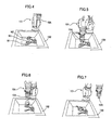
Fig. 4 , a part of every workpiece W in thebin 102 is located near the through hole W3 of another workpiece W and will interfere with thefingers 10A. Thus, since no target workpiece W is detected, thetarget workpiece detector 13 detects any of the workpieces W in thebin 102 as a disturbing-operation target workpiece W. - Next, as illustrated in
Fig. 5 , therobot 101 and thefingers 10A are operated, so that the arm portion W2 of the detected disturbing-operation target workpiece W is pinched and grasped with thefingers 10A. - Next, as illustrated in
Fig. 6 , therobot 101 is caused to lift the workpiece W, with the arm portion W2 grasped by thefingers 10A. During the lifting operation of therobot 101, thefingers 10A are opened to release the grasped workpiece W. Thus, the workpiece W is thrown from thefingers 10A to thebin 102 as illustrated inFig. 7 (workpiece disturbing operation). - In the state of
Fig. 7 , thesensor unit 103 is operated again to obtain an image captured from above thebin 102 and distance information on the image. - In the workpiece disturbing operation described above, the orientations of workpieces W in the
bin 102 have been changed from those illustrated inFig. 4 to those illustrated inFig. 7 . In the state ofFig. 7 , a target workpiece W can be detected by thetarget workpiece detector 13. - If no target workpiece W is detected even in the state of
Fig. 7 , an additional workpiece disturbing operation is performed. - If a target workpiece W is detected in the state of
Fig. 7 , thefingers 10A in a closed state are inserted into the through hole W3 of the target workpiece W as illustrated inFig. 8 . Then, as illustrated inFig. 9 , thefingers 10A inserted into the through hole W3 are opened (moved apart) to grasp the workpiece W, which is lifted by the operation of therobot 101. - Then, as illustrated in
Fig. 10 , therobot 101 is operated such that the tip of the arm portion W2 of the grasped workpiece W points downward in the direction of gravity. Thus, even if the arm portion W2 of the grasped workpiece W is engaged in the through hole W3 of a different workpiece W, the different workpiece W can be disengaged from the grasped workpiece W. Therefore, it is possible to prevent that a plurality of workpieces W are picked at the same time. - After stopping for a predetermined period of time (e.g., one second) in the state of
Fig. 10 , therobot 101 operates to transfer the grasped workpiece W toward thetransport rack 105A as illustrated inFig. 11 . - In the
workpiece picking system 100 of the present embodiment, on the basis of a result of detection performed by thesensor unit 103, thetarget workpiece detector 13 detects the presence or absence of a workpiece W on which a grasping operation can be performed. If there is no workpiece (target workpiece) W on which a grasping operation can be performed, a grasping operation is not performed. Therefore, it is possible to avoid failure caused by a grasping operation performed even when there is no properly graspable workpiece W. - When there is no target workpiece W, the arm portion W2 of any workpiece W detected as a disturbing-operation target workpiece W is grasped and released to disturb the distribution of workpieces W in the
bin 102. Thus, after it becomes possible to perform a grasping operation, a workpiece W in thebin 102 can be properly grasped. - Since a disturbing operation is performed on one of detected disturbing-operation target workpieces W, the orientation of at least the workpiece W grasped and released by the
fingers 10A in the disturbing operation is highly likely to be changed to a graspable orientation. Therefore, as compared to the case where workpieces W in thebin 102 are disturbed by a random operation, the orientation of one or more workpieces W in thebin 102 can be more reliably changed to a graspable orientation by a smaller motion. - A second embodiment will now be described. The second embodiment is the same as the first embodiment except that a plurality of different types of workpiece disturbing operations are additionally provided. Components that overlap those of the first embodiment will not be described here, and are given the same reference numerals.
- In the first embodiment described above, the grasping
information memory 12 stores, in advance, information about a workpiece disturbing operation that grasps and releases the arm portion W2 of a workpiece W (hereinafter referred to as a first disturbing operation) and a condition (workpiece condition) for performing the first disturbing operation.
In addition to this, in the second embodiment, the graspinginformation memory 12 stores, in advance, information about three workpiece disturbing operations (hereinafter referred to as second to fourth disturbing operations) and conditions (workpiece conditions) for performing the respective disturbing operations. - The second disturbing operation is an operation of grasping and releasing the head portion W1 of a workpiece W with the grasping
device 10. The workpiece condition for performing the second disturbing operation is that the workpiece W is in an orientation which does not cause interference between any graspable portion of the head portion W1 and either the graspingdevice 10 or the arm of therobot 101. - The third disturbing operation is, as illustrated in
Fig. 13 , an operation of pulling a workpiece W away from aninner wall 102A of thebin 102. The workpiece condition for performing the third disturbing operation is that there is a space between the workpiece W and its surrounding obstacle (which is theinner wall 102A here) for thefingers 10A in a closed state to pass through. - In the third disturbing operation, to prevent interference between the
inner wall 102A of thebin 102 and either the arm of therobot 101 or the graspingdevice 10, thefingers 10A enter thebin 102 at an angle from the center of thebin 102 to reach the workpiece W, which is then pulled away from theinner wall 102A. - The workpiece condition for performing the fourth disturbing operation is that a workpiece W leans against the
inner wall 102A of thebin 102 as illustrated inFig. 14 , or that a distance between theinner wall 102A and the workpiece W is smaller than a predetermined value. As illustrated inFig. 15 , the fourth disturbing operation is an operation of causing the workpiece W to fall toward the center of thebin 102. - More specifically, as illustrated in
Fig. 16 , thefingers 10A are brought into contact with the workpiece W leaning against theinner wall 102A at a position below the center of gravity of the workpiece W, in the direction of arrow P. Thus, as indicated by dotted lines inFig. 16 , the workpiece W is caused to fall toward the center of thebin 102, for example, by reactive force of theinner wall 102A. - In the present embodiment, the order of priority of the disturbing operations is as follows: the first disturbing operation, the second disturbing operation, the third disturbing operation, and the fourth disturbing operation. If it is possible to perform the first disturbing operation, the first disturbing operation is performed. If the condition for performing the first disturbing operation is not satisfied, a determination is made as to whether the condition for performing the second disturbing operation is satisfied. If the condition for performing the second disturbing operation is satisfied, the second disturbing operation is performed. If the condition for performing the second disturbing operation is not satisfied, a determination is made as to whether the condition for performing the third disturbing operation is satisfied. If the condition for performing the third disturbing operation is satisfied, the third disturbing operation is performed. If the condition for performing the third disturbing operation is not satisfied, a determination is made as to whether the condition for performing the fourth disturbing operation is satisfied. If the condition for performing the fourth disturbing operation is satisfied, the fourth disturbing operation is performed. If the condition for performing the fourth disturbing operation is not satisfied, the workpiece picking operation is stopped on the basis of the assumption that there is no graspable workpiece W in the
bin 102. - Instead of stopping the workpiece picking operation, the
workpiece picking system 100 may display an error message on a display of therobot control device 104. - In the first embodiment described above, if both the grasping operation and the first disturbing operation cannot be performed on any workpiece W, the
workpiece picking system 100 may not be able to accurately handle workpieces However, theworkpiece picking system 100 of the second embodiment provides not only the first disturbing operation, but also the second to fourth disturbing operations. Therefore, even if both the grasping operation and the first disturbing operation cannot be performed on any workpiece W, execution of a grasping operation is made possible by performing any of the second to fourth disturbing operations It is thus possible to avoid inconvenience, such as failure in handling workpieces W. - In the second disturbing operation, when a workpiece W is in an orientation which does not allow the
fingers 10A to be fully inserted into the through hole W3 and does not allow the arm portion W2 to be firmly grasped, the head portion W1 of the workpiece W is grasped and released. This can change the positions and orientations of a plurality of workpieces W in thebin 102 and make it possible to perform a grasping operation on one or more workpieces W. - When, for example, the number of workpieces W remaining in the
bin 102 becomes small during a workpiece grasping operation, the arm of therobot 101 or the graspingdevice 10 may interfere with theinner wall 102A of thebin 102.
In such a case, in the third disturbing operation, the graspingdevice 10 is brought close to a workpiece W from an angle which does not cause interference (contact) with theinner wall 102A, and then the graspingdevice 10 pulls the workpiece W away from theinner wall 102A. Since the workpiece W thus becomes distant from theinner wall 102A, a more reliable workpiece grasping operation can be performed next time. - In the fourth disturbing operation, when a workpiece W leans against the
inner wall 102A of thebin 102, the workpiece W is caused to fall from theinner wall 102A toward the center of thebin 102. Therefore, a more reliable workpiece grasping operation can be performed next time. - A modification of the first and second embodiments will now be described. The present modification is realized by modifying the functional configuration of the
robot control device 104 and thesensor controller 3 of the first or second embodiment described above. - Specifically, as illustrated in
Fig. 17 , thesensor controller 3 in thesensor unit 103 includes aworkpiece shape memory 21, a graspinginformation memory 22, and atarget workpiece detector 23. Also, as illustrated inFig. 17 , therobot control device 104 includes agrasping operation controller 24, adisturbing operation controller 25, and arobot controller 26. - The
sensor controller 3 is connected to an input device, such as an external personal computer (PC). Thus, three-dimensional shape data of workpieces W measured in advance, and grasping operation information including grasping position information and grasping method information are input to thesensor controller 3 and stored in theworkpiece shape memory 21 and the graspinginformation memory 22. Note that the grasping position information is information about which portion of a workpiece W is to be grasped by the graspingdevice 10, and the grasping method information is information about how the workpiece W is to be grasped by the graspingdevice 10. - The
target workpiece detector 23 detects the orientations of workpieces W in thebin 102, for example, through a matching process using detection signals from the camera 1 and thelaser scanner 2. Then, thetarget workpiece detector 23 detects a target workpiece W that satisfies a predetermined condition, and sends the position and orientation information about the detected target workpiece W to therobot control device 104. - If no target workpiece W is detected, the
target workpiece detector 23 detects a workpiece W on which a workpiece disturbing operation can be performed as a disturbing-operation target workpiece W. Then, thetarget workpiece detector 23 sends the position and orientation information about the detected disturbing-operation target workpiece W to therobot control device 104. - The
robot control device 104 illustrated inFig. 1 is provided as an integral computing device. However, therobot control device 104 may be provided in combination with another computing device as illustrated inFig. 17 . - Some embodiments of the present invention have been described above. The workpiece picking system of the present invention is not limited to the foregoing embodiments, and may be appropriately modified without departing from the scope of the present invention.
- For example, in the first embodiment, a disturbing-operation target workpiece to be used in a disturbing operation is detected when no graspable workpiece (target workpiece) is detected. However, the mode of disturbing operation may be selected appropriately. When workpieces and the grasping device are relatively resistant to shocks and if no graspable workpiece (target workpiece) is detected, the grasping device may be inserted into the bin through a predetermined path and may stir the workpieces in the bin. This makes it possible that a disturbing operation be done through a simpler calculation process.
- In the second embodiment, one of the plurality of workpiece disturbing operations is performed depending on the condition. However, the number of types of workpiece disturbing operations may be either one or more.
- Also in the second embodiment, the first disturbing operation involves grasping and releasing the arm portion of a workpiece, and the second workpiece disturbing operation involves grasping and releasing the head portion of a workpiece. However, such a distinction may be removed.
That is, a workpiece having any graspable portion may be detected as a disturbing-operation target workpiece. - The shape of workpieces is not limited to that described in the embodiments. The present invention can be applied to workpieces of any shape by setting a workpiece disturbing operation appropriate for the shape.
- Although the shape sensor is disposed near the bin in the embodiments described above, the shape sensor may be mounted on the robot. In this case, the detectable range of the shape sensor can be changed by appropriately operating the robot.
Claims (12)
- A robot system (100) comprising:a robot (101) having a grasper (10) that grasps a workpiece (W) in a bin (102) containing a plurality of workpieces; anda robot control device (104) configured to control an operation of the robot,wherein the robot control device includes
a workpiece shape memory (11, 21) configured to store a shape of the workpieces;
a target workpiece detector (13, 23) configured to detect a graspable workpiece from the workpieces in the bin on the basis of a result of detection performed by a shape sensor (103) that detects shape information about the workpieces in the bin, the graspable workpiece being a workpiece satisfying a condition stored in advance;
a grasping information memory (12, 22) configured to store a grasping position indicating which portion of the graspable workpiece is to be grasped by the robot;
a grasping operation controller (14, 24) configured to cause the robot to grasp the graspable workpiece detected by the target workpiece detector and pick the grasped workpiece from the bin; and
a disturbing operation controller (15, 25) configured to cause, if no graspable workpiece is detected by the target workpiece detector, the robot to perform a workpiece disturbing operation that disturbs a distribution of the workpieces in the bin. - The robot system according to Claim 1, wherein on the basis of a result of detection performed again by the shape sensor after the workpiece disturbing operation, the target workpiece detector detects a graspable workpiece from the workpieces in the bin, the graspable workpiece being a workpiece satisfying the condition stored in advance.
- The robot system according to Claim 1 or 2, wherein the shape sensor includes a camera (1) that captures an image of the bin, and a distance sensor (2) that detects distance information about the workpieces in the bin.
- The robot system according to any one of Claims 1 to 3, wherein
the grasping information memory stores, in advance, operation information for performing a workpiece disturbing operation; and
the disturbing operation controller performs the workpiece disturbing operation on the basis of the operation information if no graspable workpiece is detected by the target workpiece detector. - The robot system according to any one of Claims 1 to 4, wherein each of the workpieces has a circular through hole (W3) and a rod-like portion (W2) extending in one direction from the through hole; and
the grasping operation controller inserts the grasper of the robot into the through hole of the workpiece, and widens the grasper to grasp the workpiece. - The robot system according to Claim 5, wherein the grasping operation controller operates the robot such that after the robot grasps the workpiece, a tip of the rod-like portion points downward in the direction of gravity.
- The robot system according to any one of Claims 1 to 6, wherein
the grasping information memory stores operation information about a plurality of different types of workpiece disturbing operations in advance; and
the disturbing operation controller performs one of the plurality of different types of workpiece disturbing operations, the one satisfying a predetermined workpiece condition. - The robot system according to Claim 7, wherein the operation information about the plurality of different types of workpiece disturbing operations include information about an operation that pulls a workpiece away from an inner wall (102A) of the bin.
- The robot system according to Claim 7 or 8, wherein the operation information about the plurality of different types of workpiece disturbing operations include information about an operation that causes a workpiece to fall from an inner wall (102A) of the bin toward the center of the bin, the operation being performed when the predetermined workpiece condition is that the workpiece leans against the inner wall of the bin.
- The robot system according to any one of Claims 1 to 9, further comprising:the bin containing a plurality of workpieces; andthe shape sensor configured to detect shape information about the workpieces in the bin.
- A workpiece picking method comprising:detecting shape information about a plurality of workpieces (W) in a bin (102) by using a shape sensor (103);detecting the presence or absence of a graspable workpiece on the basis of a result of detection performed by the shape sensor, the graspable workpiece being a workpiece satisfying a condition stored in advance;causing, if no graspable workpiece is detected, a robot (101) to perform a workpiece disturbing operation that disturbs a distribution of the workpieces in the bin; andcausing, if a graspable workpiece is detected, the robot to grasp the detected workpiece.
- The workpiece picking method according to Claim 11, further comprising:detecting, after the workpiece disturbing operation, shape information about the workpieces in the bin again by using the shape sensor;causing, if no graspable workpiece is detected, the robot to perform an additional workpiece disturbing operation that disturbs a distribution of the workpieces in the bin; andcausing, if a graspable workpiece is detected, the robot to grasp the detected workpiece.
Applications Claiming Priority (2)
| Application Number | Priority Date | Filing Date | Title |
|---|---|---|---|
| JP2009245091 | 2009-10-26 | ||
| JP2010027552A JP5402697B2 (en) | 2009-10-26 | 2010-02-10 | Robot apparatus, work picking system and work picking method |
Publications (2)
| Publication Number | Publication Date |
|---|---|
| EP2314425A2 true EP2314425A2 (en) | 2011-04-27 |
| EP2314425A3 EP2314425A3 (en) | 2012-01-04 |
Family
ID=43348544
Family Applications (1)
| Application Number | Title | Priority Date | Filing Date |
|---|---|---|---|
| EP10185324A Withdrawn EP2314425A3 (en) | 2009-10-26 | 2010-10-01 | Robot system and workpiece picking method |
Country Status (4)
| Country | Link |
|---|---|
| US (1) | US8660685B2 (en) |
| EP (1) | EP2314425A3 (en) |
| JP (1) | JP5402697B2 (en) |
| CN (1) | CN102049778A (en) |
Cited By (11)
| Publication number | Priority date | Publication date | Assignee | Title |
|---|---|---|---|---|
| DE102015013925A1 (en) | 2015-01-16 | 2016-07-21 | Sk-Technologies Ug (Haftungsbeschränkt) | Arrangement for the supply and method for the automated collection and removal of workpieces |
| EP3195992A1 (en) | 2016-01-23 | 2017-07-26 | SK-Technologies GmbH | Assembly and method for automated detection and unloading of workpieces from an unordered collection |
| DE102019130902A1 (en) * | 2019-05-31 | 2020-12-03 | Mujin, Inc. | A robot system with a dynamic packing mechanism |
| DE102019212839B4 (en) * | 2018-09-10 | 2020-12-10 | Kabushiki Kaisha Toshiba | Object handling device and computer program product |
| US10953549B2 (en) | 2019-05-31 | 2021-03-23 | Mujin, Inc. | Robotic system with error detection and dynamic packing mechanism |
| US11077554B2 (en) | 2019-05-31 | 2021-08-03 | Mujin, Inc. | Controller and control method for robotic system |
| EP3822202A4 (en) * | 2018-09-10 | 2022-04-06 | Kabushiki Kaisha Toshiba | COLLECTION SYSTEM, INFORMATION PROCESSING DEVICE AND COMPUTER READABLE RECORDING MEDIA |
| US11319166B2 (en) | 2019-05-31 | 2022-05-03 | Mujin, Inc. | Robotic system with packing mechanism |
| US11472640B2 (en) | 2019-05-31 | 2022-10-18 | Mujin, Inc. | Robotic system for palletizing packages using real-time placement simulation |
| US11591168B2 (en) | 2019-05-31 | 2023-02-28 | Mujin, Inc. | Robotic system for processing packages arriving out of sequence |
| CN115916483A (en) * | 2020-09-09 | 2023-04-04 | 欧姆龙株式会社 | Robot system and picking method |
Families Citing this family (48)
| Publication number | Priority date | Publication date | Assignee | Title |
|---|---|---|---|---|
| JP5558585B2 (en) * | 2010-11-17 | 2014-07-23 | 三菱電機株式会社 | Work picking device |
| JP5767464B2 (en) * | 2010-12-15 | 2015-08-19 | キヤノン株式会社 | Information processing apparatus, information processing apparatus control method, and program |
| JP5533727B2 (en) * | 2011-02-18 | 2014-06-25 | 株式会社安川電機 | Work picking system |
| JP2012206219A (en) * | 2011-03-30 | 2012-10-25 | Seiko Epson Corp | Robot control device and robot system |
| JP5835926B2 (en) * | 2011-04-11 | 2015-12-24 | キヤノン株式会社 | Information processing apparatus, information processing apparatus control method, and program |
| JP5852364B2 (en) * | 2011-08-26 | 2016-02-03 | キヤノン株式会社 | Information processing apparatus, information processing apparatus control method, and program |
| JP5447483B2 (en) | 2011-10-04 | 2014-03-19 | 株式会社安川電機 | Robot system and method of manufacturing workpiece |
| JP2013078825A (en) * | 2011-10-04 | 2013-05-02 | Yaskawa Electric Corp | Robot apparatus, robot system, and method for manufacturing workpiece |
| JP5582126B2 (en) * | 2011-10-13 | 2014-09-03 | 株式会社安川電機 | Work take-out system, robot apparatus, and workpiece manufacturing method |
| JP5606424B2 (en) * | 2011-11-04 | 2014-10-15 | 三菱電機株式会社 | Component extraction method and component extraction system |
| JP5935383B2 (en) * | 2012-02-24 | 2016-06-15 | 株式会社デンソーウェーブ | Component supply apparatus and component supply method |
| JP2013184273A (en) | 2012-03-09 | 2013-09-19 | Sony Corp | Robot apparatus, method of controlling robot apparatus, and computer program |
| JP5848173B2 (en) * | 2012-03-16 | 2016-01-27 | 日本発條株式会社 | Hanger line work hook control device and method |
| JP5614553B2 (en) * | 2012-09-14 | 2014-10-29 | 株式会社安川電機 | Robot equipment |
| JP2014138964A (en) * | 2013-01-21 | 2014-07-31 | Toyota Motor Corp | Robot hand control device and robot hand control method |
| JP5929854B2 (en) * | 2013-07-31 | 2016-06-08 | 株式会社安川電機 | Robot system and method of manufacturing workpiece |
| KR102081139B1 (en) * | 2014-03-12 | 2020-02-25 | 한국전자통신연구원 | Object peaking system, object detecting device and method thereof |
| JP6545671B2 (en) * | 2014-05-27 | 2019-07-17 | 川崎重工業株式会社 | End effector, industrial robot, and method of operating the same |
| JP6360747B2 (en) * | 2014-08-22 | 2018-07-18 | 西部電機株式会社 | Amorphous body position estimation method, amorphous body position estimation apparatus and program |
| US9597801B2 (en) * | 2014-10-21 | 2017-03-21 | Centurylink Intellectual Property Llc | Automated data center |
| US9669543B1 (en) | 2015-12-11 | 2017-06-06 | Amazon Technologies, Inc. | Validation of robotic item grasping |
| JP6426690B2 (en) * | 2016-12-22 | 2018-11-21 | ファナック株式会社 | Article picking system and method for picking out piled articles |
| JP6453922B2 (en) | 2017-02-06 | 2019-01-16 | ファナック株式会社 | Work picking apparatus and work picking method for improving work picking operation |
| DE102017002354B4 (en) | 2017-03-10 | 2022-04-07 | Swisslog Ag | Transporting objects, in particular picking goods, using a robot |
| JP6526100B2 (en) * | 2017-04-28 | 2019-06-05 | ファナック株式会社 | Material pick-up system |
| JP7149267B2 (en) * | 2017-05-15 | 2022-10-06 | Thk株式会社 | gripping system |
| WO2018212194A1 (en) * | 2017-05-15 | 2018-11-22 | Thk株式会社 | Gripping system |
| US11298818B2 (en) * | 2017-05-15 | 2022-04-12 | Thk Co., Ltd. | Gripping system |
| US10894316B2 (en) * | 2017-06-06 | 2021-01-19 | Seiko Epson Corporation | Control apparatus and robot system |
| JP6992415B2 (en) * | 2017-06-06 | 2022-01-13 | セイコーエプソン株式会社 | Robot system control device and robot system |
| US11007648B2 (en) * | 2017-09-05 | 2021-05-18 | Abb Schweiz Ag | Robotic system for grasping objects |
| JP2019084601A (en) * | 2017-11-02 | 2019-06-06 | キヤノン株式会社 | Information processing apparatus, gripping system and information processing method |
| JP6784659B2 (en) * | 2017-11-27 | 2020-11-11 | ニッタ株式会社 | Grippers, grippers and industrial robots |
| CN107775023A (en) * | 2017-11-28 | 2018-03-09 | 重庆华数机器人有限公司 | A kind of multi-functional deburring equipment |
| JP7039328B2 (en) | 2018-02-27 | 2022-03-22 | ニッタ株式会社 | Gripping devices and industrial robots |
| JP7112211B2 (en) * | 2018-02-28 | 2022-08-03 | ニッタ株式会社 | Grasping device and industrial robot |
| JP7112210B2 (en) * | 2018-02-28 | 2022-08-03 | ニッタ株式会社 | Grasping device and industrial robot |
| JP6879238B2 (en) * | 2018-03-13 | 2021-06-02 | オムロン株式会社 | Work picking device and work picking method |
| WO2019239563A1 (en) | 2018-06-14 | 2019-12-19 | ヤマハ発動機株式会社 | Robot system |
| CN109146939A (en) * | 2018-09-07 | 2019-01-04 | 中科新松有限公司 | A kind of generation method and system of workpiece grabbing template |
| CN110228068A (en) * | 2019-06-14 | 2019-09-13 | 广西科技大学 | A kind of robot plane setting quick positioning system and its method for rapidly positioning |
| US11911901B2 (en) | 2019-09-07 | 2024-02-27 | Embodied Intelligence, Inc. | Training artificial networks for robotic picking |
| CN114641378B (en) | 2019-09-07 | 2024-09-27 | 具现智能有限公司 | Systems and methods for robotic picking |
| EP4025394A1 (en) * | 2019-09-07 | 2022-07-13 | Embodied Intelligence, Inc. | Systems and methods for robotic picking and perturbation |
| WO2021046530A1 (en) | 2019-09-07 | 2021-03-11 | Embodied Intelligence, Inc. | Three-dimensional computer vision system for robotic devices |
| WO2022151178A1 (en) * | 2021-01-14 | 2022-07-21 | Abb Schweiz Ag | Apparatus and method for feeding flexible ring-shaped workpieces |
| WO2024009408A1 (en) * | 2022-07-05 | 2024-01-11 | 川崎重工業株式会社 | Robot system, robot control method, and robot control program |
| JP7460744B1 (en) | 2022-12-27 | 2024-04-02 | 京セラ株式会社 | Robot control device, robot, stirring method and program |
Citations (1)
| Publication number | Priority date | Publication date | Assignee | Title |
|---|---|---|---|---|
| JP2009128201A (en) | 2007-11-26 | 2009-06-11 | Mitsubishi Electric Corp | Position and orientation recognition device |
Family Cites Families (19)
| Publication number | Priority date | Publication date | Assignee | Title |
|---|---|---|---|---|
| JPH0729266B2 (en) * | 1986-06-13 | 1995-04-05 | 株式会社ブリヂストン | Grasping device for parts |
| US4783108A (en) * | 1986-06-13 | 1988-11-08 | Bridgestone Corporation | Catching head of apparatus for handling parts such as cylinder blocks and the like |
| CN2072894U (en) * | 1990-05-24 | 1991-03-13 | 魏平源 | Miniature remote-control manipulators |
| JPH08305433A (en) * | 1995-04-27 | 1996-11-22 | Nissan Motor Co Ltd | Depalletizing controller |
| JPH11300670A (en) * | 1998-04-21 | 1999-11-02 | Fanuc Ltd | Article picking-up device |
| JP2000263480A (en) * | 1999-03-12 | 2000-09-26 | Meidensha Corp | Bin picking device |
| US6721444B1 (en) * | 1999-03-19 | 2004-04-13 | Matsushita Electric Works, Ltd. | 3-dimensional object recognition method and bin-picking system using the method |
| JP3421608B2 (en) * | 1999-04-08 | 2003-06-30 | ファナック株式会社 | Teaching model generator |
| JP2002200588A (en) * | 2000-12-28 | 2002-07-16 | Denso Corp | Method and apparatus for detecting gripping position of grippable part by robot |
| JP4004899B2 (en) * | 2002-09-02 | 2007-11-07 | ファナック株式会社 | Article position / orientation detection apparatus and article removal apparatus |
| JP3930490B2 (en) * | 2004-04-23 | 2007-06-13 | ファナック株式会社 | Article take-out device |
| CN101890720B (en) * | 2004-07-13 | 2012-01-11 | 松下电器产业株式会社 | Article holding system, robot, and method of controlling robot |
| JP4359268B2 (en) * | 2005-07-15 | 2009-11-04 | 本田技研工業株式会社 | Parts supply device |
| EP1992455B1 (en) * | 2006-02-02 | 2012-04-11 | Kabushiki Kaisha Yaskawa Denki | Robot system |
| JP4199264B2 (en) * | 2006-05-29 | 2008-12-17 | ファナック株式会社 | Work picking apparatus and method |
| US7313464B1 (en) * | 2006-09-05 | 2007-12-25 | Adept Technology Inc. | Bin-picking system for randomly positioned objects |
| JP2009172720A (en) * | 2008-01-24 | 2009-08-06 | Kondo Seisakusho:Kk | Bin picking device |
| JP2010005722A (en) * | 2008-06-25 | 2010-01-14 | Ihi Corp | Workpiece feeder for use in picking bulk items |
| US8862269B2 (en) * | 2008-08-29 | 2014-10-14 | Abb Research Ltd. | Robotic picking of parts from a bin |
-
2010
- 2010-02-10 JP JP2010027552A patent/JP5402697B2/en active Active
- 2010-10-01 EP EP10185324A patent/EP2314425A3/en not_active Withdrawn
- 2010-10-25 CN CN2010105221835A patent/CN102049778A/en active Pending
- 2010-10-25 US US12/911,667 patent/US8660685B2/en not_active Expired - Fee Related
Patent Citations (1)
| Publication number | Priority date | Publication date | Assignee | Title |
|---|---|---|---|---|
| JP2009128201A (en) | 2007-11-26 | 2009-06-11 | Mitsubishi Electric Corp | Position and orientation recognition device |
Cited By (22)
| Publication number | Priority date | Publication date | Assignee | Title |
|---|---|---|---|---|
| DE102015013925A1 (en) | 2015-01-16 | 2016-07-21 | Sk-Technologies Ug (Haftungsbeschränkt) | Arrangement for the supply and method for the automated collection and removal of workpieces |
| EP3195992A1 (en) | 2016-01-23 | 2017-07-26 | SK-Technologies GmbH | Assembly and method for automated detection and unloading of workpieces from an unordered collection |
| DE102016000611A1 (en) | 2016-01-23 | 2017-07-27 | Sk-Technologies Ug (Haftungsbeschränkt) | Arrangement and method for the automated collection and removal of workpieces from disordered accumulation |
| EP3822202A4 (en) * | 2018-09-10 | 2022-04-06 | Kabushiki Kaisha Toshiba | COLLECTION SYSTEM, INFORMATION PROCESSING DEVICE AND COMPUTER READABLE RECORDING MEDIA |
| US11498210B2 (en) | 2018-09-10 | 2022-11-15 | Kabushiki Kaisha Toshiba | Object handling device and computer program product |
| DE102019212839B4 (en) * | 2018-09-10 | 2020-12-10 | Kabushiki Kaisha Toshiba | Object handling device and computer program product |
| US11472640B2 (en) | 2019-05-31 | 2022-10-18 | Mujin, Inc. | Robotic system for palletizing packages using real-time placement simulation |
| US11591168B2 (en) | 2019-05-31 | 2023-02-28 | Mujin, Inc. | Robotic system for processing packages arriving out of sequence |
| US10953549B2 (en) | 2019-05-31 | 2021-03-23 | Mujin, Inc. | Robotic system with error detection and dynamic packing mechanism |
| US11319166B2 (en) | 2019-05-31 | 2022-05-03 | Mujin, Inc. | Robotic system with packing mechanism |
| DE102019130902B4 (en) * | 2019-05-31 | 2021-01-14 | Mujin, Inc. | A robot system with a dynamic packing mechanism |
| US11488323B2 (en) | 2019-05-31 | 2022-11-01 | Mujin, Inc. | Robotic system with dynamic packing mechanism |
| DE102019130902A1 (en) * | 2019-05-31 | 2020-12-03 | Mujin, Inc. | A robot system with a dynamic packing mechanism |
| US11077554B2 (en) | 2019-05-31 | 2021-08-03 | Mujin, Inc. | Controller and control method for robotic system |
| US12311551B2 (en) | 2019-05-31 | 2025-05-27 | Mujin, Inc. | Controller and control method for robotic system |
| US11794346B2 (en) | 2019-05-31 | 2023-10-24 | Mujin, Inc. | Robotic system with error detection and dynamic packing mechanism |
| US12065318B2 (en) | 2019-05-31 | 2024-08-20 | Mujin, Inc. | Robotic system with packing mechanism |
| US12084299B2 (en) | 2019-05-31 | 2024-09-10 | Mujin, Inc. | Robotic system for palletizing packages using real-time placement simulation |
| US12162166B2 (en) | 2019-05-31 | 2024-12-10 | Mujin, Inc. | Robotic system with error detection and dynamic packing mechanism |
| US12227374B2 (en) | 2019-05-31 | 2025-02-18 | Mujin, Inc. | Robotic system with dynamic packing mechanism |
| US12304750B2 (en) | 2019-05-31 | 2025-05-20 | Mujin, Inc. | Robotic system for processing packages arriving out of sequence |
| CN115916483A (en) * | 2020-09-09 | 2023-04-04 | 欧姆龙株式会社 | Robot system and picking method |
Also Published As
| Publication number | Publication date |
|---|---|
| JP2011115930A (en) | 2011-06-16 |
| US8660685B2 (en) | 2014-02-25 |
| JP5402697B2 (en) | 2014-01-29 |
| CN102049778A (en) | 2011-05-11 |
| US20110098859A1 (en) | 2011-04-28 |
| EP2314425A3 (en) | 2012-01-04 |
Similar Documents
| Publication | Publication Date | Title |
|---|---|---|
| US8660685B2 (en) | Robot system and workpiece picking method | |
| JP5229253B2 (en) | Robot system, robot apparatus and workpiece picking method | |
| JP7548516B2 (en) | Robotic system with automated package scanning and registration mechanism and method of operation thereof | |
| JP6088563B2 (en) | Work picking robot system having position and orientation conversion operation function, and work picking method | |
| JP5905549B1 (en) | Article picking device for picking up bulk goods | |
| JP4938115B2 (en) | Work take-out device and work take-out method | |
| US7313464B1 (en) | Bin-picking system for randomly positioned objects | |
| US12421054B2 (en) | Robotic multi-surface gripper assemblies and methods for operating the same | |
| JP3805310B2 (en) | Work take-out device | |
| KR102662077B1 (en) | Robotic hands, robots and robotic systems | |
| US20230286140A1 (en) | Systems and methods for robotic system with object handling | |
| JP2007313624A (en) | Work picking apparatus and method | |
| JP2001179669A (en) | Control device for robot | |
| US20180050453A1 (en) | Fixture Manipulation Systems and Methods | |
| CN111687817A (en) | Robot system with steering mechanism and method of operating the same | |
| JP2011093015A (en) | Control device of hand-eye bin picking robot | |
| JP4390758B2 (en) | Work take-out device | |
| EP4180188B1 (en) | Cargo handling apparatus, control device, cargo handling, method, program, and storage medium | |
| JP2000263480A (en) | Bin picking device | |
| JP4156822B2 (en) | Handling device | |
| JP7286524B2 (en) | Picking robot, picking method and program | |
| JP2017094443A (en) | Work take-out device | |
| EP4498342A1 (en) | Card insertion system and card removal system | |
| CN116061192A (en) | Systems and methods for robotic systems with object handling | |
| WO2026009958A1 (en) | Picking method and picking control device |
Legal Events
| Date | Code | Title | Description |
|---|---|---|---|
| PUAI | Public reference made under article 153(3) epc to a published international application that has entered the european phase |
Free format text: ORIGINAL CODE: 0009012 |
|
| AK | Designated contracting states |
Kind code of ref document: A2 Designated state(s): AL AT BE BG CH CY CZ DE DK EE ES FI FR GB GR HR HU IE IS IT LI LT LU LV MC MK MT NL NO PL PT RO RS SE SI SK SM TR |
|
| AX | Request for extension of the european patent |
Extension state: BA ME |
|
| PUAL | Search report despatched |
Free format text: ORIGINAL CODE: 0009013 |
|
| AK | Designated contracting states |
Kind code of ref document: A3 Designated state(s): AL AT BE BG CH CY CZ DE DK EE ES FI FR GB GR HR HU IE IS IT LI LT LU LV MC MK MT NL NO PL PT RO RS SE SI SK SM TR |
|
| AX | Request for extension of the european patent |
Extension state: BA ME |
|
| RIC1 | Information provided on ipc code assigned before grant |
Ipc: B25J 9/16 20060101AFI20111125BHEP |
|
| 17P | Request for examination filed |
Effective date: 20120322 |
|
| STAA | Information on the status of an ep patent application or granted ep patent |
Free format text: STATUS: THE APPLICATION HAS BEEN WITHDRAWN |
|
| 18W | Application withdrawn |
Effective date: 20160822 |