EP2313203B1 - Cyclone with improved separation of gas from gas laden liquid streams also at reduced flow volumes - Google Patents
Cyclone with improved separation of gas from gas laden liquid streams also at reduced flow volumes Download PDFInfo
- Publication number
- EP2313203B1 EP2313203B1 EP08767113.7A EP08767113A EP2313203B1 EP 2313203 B1 EP2313203 B1 EP 2313203B1 EP 08767113 A EP08767113 A EP 08767113A EP 2313203 B1 EP2313203 B1 EP 2313203B1
- Authority
- EP
- European Patent Office
- Prior art keywords
- cyclone
- flow
- outlet
- gas
- insertion pipe
- Prior art date
- Legal status (The legal status is an assumption and is not a legal conclusion. Google has not performed a legal analysis and makes no representation as to the accuracy of the status listed.)
- Not-in-force
Links
- 239000007788 liquid Substances 0.000 title claims description 39
- 238000000926 separation method Methods 0.000 title description 7
- 238000003780 insertion Methods 0.000 claims description 81
- 230000037431 insertion Effects 0.000 claims description 81
- 239000006260 foam Substances 0.000 claims description 14
- 230000015572 biosynthetic process Effects 0.000 claims description 7
- 238000000034 method Methods 0.000 claims description 7
- 230000003247 decreasing effect Effects 0.000 claims description 4
- 238000011144 upstream manufacturing Methods 0.000 claims description 4
- 238000004519 manufacturing process Methods 0.000 description 11
- JTJMJGYZQZDUJJ-UHFFFAOYSA-N phencyclidine Chemical class C1CCCCN1C1(C=2C=CC=CC=2)CCCCC1 JTJMJGYZQZDUJJ-UHFFFAOYSA-N 0.000 description 7
- 230000001105 regulatory effect Effects 0.000 description 4
- 238000010411 cooking Methods 0.000 description 3
- 238000010438 heat treatment Methods 0.000 description 3
- 230000009467 reduction Effects 0.000 description 3
- 239000011122 softwood Substances 0.000 description 3
- 241000218657 Picea Species 0.000 description 2
- 235000008331 Pinus X rigitaeda Nutrition 0.000 description 2
- 241000018646 Pinus brutia Species 0.000 description 2
- 235000011613 Pinus brutia Nutrition 0.000 description 2
- 230000008859 change Effects 0.000 description 2
- 230000001276 controlling effect Effects 0.000 description 2
- 230000003628 erosive effect Effects 0.000 description 2
- 239000007791 liquid phase Substances 0.000 description 2
- 239000012071 phase Substances 0.000 description 2
- QAOWNCQODCNURD-UHFFFAOYSA-L Sulfate Chemical compound [O-]S([O-])(=O)=O QAOWNCQODCNURD-UHFFFAOYSA-L 0.000 description 1
- 230000009471 action Effects 0.000 description 1
- 230000004913 activation Effects 0.000 description 1
- 229920002678 cellulose Polymers 0.000 description 1
- 239000001913 cellulose Substances 0.000 description 1
- 230000001419 dependent effect Effects 0.000 description 1
- 238000009434 installation Methods 0.000 description 1
- 230000002093 peripheral effect Effects 0.000 description 1
- 230000008569 process Effects 0.000 description 1
- 238000011084 recovery Methods 0.000 description 1
- 238000005507 spraying Methods 0.000 description 1
- 229910021653 sulphate ion Inorganic materials 0.000 description 1
- 239000002023 wood Substances 0.000 description 1
Images

Classifications
-
- B—PERFORMING OPERATIONS; TRANSPORTING
- B04—CENTRIFUGAL APPARATUS OR MACHINES FOR CARRYING-OUT PHYSICAL OR CHEMICAL PROCESSES
- B04C—APPARATUS USING FREE VORTEX FLOW, e.g. CYCLONES
- B04C5/00—Apparatus in which the axial direction of the vortex is reversed
- B04C5/02—Construction of inlets by which the vortex flow is generated, e.g. tangential admission, the fluid flow being forced to follow a downward path by spirally wound bulkheads, or with slightly downwardly-directed tangential admission
- B04C5/04—Tangential inlets
-
- B—PERFORMING OPERATIONS; TRANSPORTING
- B01—PHYSICAL OR CHEMICAL PROCESSES OR APPARATUS IN GENERAL
- B01D—SEPARATION
- B01D19/00—Degasification of liquids
- B01D19/0021—Degasification of liquids by bringing the liquid in a thin layer
- B01D19/0026—Degasification of liquids by bringing the liquid in a thin layer in rotating vessels or in vessels containing movable parts
-
- B—PERFORMING OPERATIONS; TRANSPORTING
- B01—PHYSICAL OR CHEMICAL PROCESSES OR APPARATUS IN GENERAL
- B01D—SEPARATION
- B01D19/00—Degasification of liquids
- B01D19/0036—Flash degasification
-
- B—PERFORMING OPERATIONS; TRANSPORTING
- B01—PHYSICAL OR CHEMICAL PROCESSES OR APPARATUS IN GENERAL
- B01D—SEPARATION
- B01D19/00—Degasification of liquids
- B01D19/0063—Regulation, control including valves and floats
-
- B—PERFORMING OPERATIONS; TRANSPORTING
- B04—CENTRIFUGAL APPARATUS OR MACHINES FOR CARRYING-OUT PHYSICAL OR CHEMICAL PROCESSES
- B04C—APPARATUS USING FREE VORTEX FLOW, e.g. CYCLONES
- B04C11/00—Accessories, e.g. safety or control devices, not otherwise provided for, e.g. regulators, valves in inlet or overflow ducting
-
- B—PERFORMING OPERATIONS; TRANSPORTING
- B04—CENTRIFUGAL APPARATUS OR MACHINES FOR CARRYING-OUT PHYSICAL OR CHEMICAL PROCESSES
- B04C—APPARATUS USING FREE VORTEX FLOW, e.g. CYCLONES
- B04C5/00—Apparatus in which the axial direction of the vortex is reversed
- B04C5/12—Construction of the overflow ducting, e.g. diffusing or spiral exits
- B04C5/13—Construction of the overflow ducting, e.g. diffusing or spiral exits formed as a vortex finder and extending into the vortex chamber; Discharge from vortex finder otherwise than at the top of the cyclone; Devices for controlling the overflow
Definitions
- the following invention relates to a cyclone, mainly for separating gas/vapour from a pressurised gas laden liquid stream, which separation is obtained by pressure reduction of the gas laden liquid stream.
- the gas laden liquid stream is preferably pressurised spent cooking liquid obtained from a digester used in pulp production.
- the cyclone comprises a cylindrical casing, an tangential inlet arrangement for the pressurised gas laden liquid stream, and in opposite ends of the cylindrical casing an outlet line for liquid and an outlet line for vapour and/or gas. Said inlet arrangement being connected to a supply line with at least one valve.
- the invention relates to a cyclone of the abovementioned type which is cost-effective and which can in a flexible manner be controlled during operation with regard to different operating conditions.
- the invention also relates to a method for counteracting foam formation.
- Cyclones are used in the main for separating a gas/vapour phase from a liquid phase.
- use is in general made of cyclones which are specially manufactured with regard to the operating conditions in which the cyclone is principally to work.
- cyclones known today are in most cases constructed in such a manner that they cannot be adapted to different operating conditions, at least not without a considerable effort, as a result of which they often, in the event of a change in the production process, come to be used in operating conditions which are not optimum.
- the aim of the following invention is to produce a cyclone which at least in the main eliminates the abovementioned problem, so that a cyclone is made available, with the aid of which it is possible in a flexible manner during operation of the cyclone to adapt the inlet arrangement to prevailing operating conditions so that the outflow rate inside the cyclone can be optimised and that such an inlet arrangement is constructed in such a manner that it counteracts the appearance of foam.
- an inlet arrangement which consists of at least one additional insertion pipe arranged in the inlet opening and connected to the common supply source, and one sensor arranged to detect a parameter representative for the order of flow from the common supply source and said sensor connected to a control member for controlling the position of a valve member in at least one insertion pipe depending on the order of flow from the common supply source.
- Each insertion pipe has preferably an essentially constant and smooth cross-sectional area, the length of which exceeds 1 meter. In the preferred case, the length of said insertion pipe exceeds 2 meters, and it has proved to be particularly advantageous in connection with pressure release of spent cooking liquid from a digester for pulp production if the insertion pipe has a length of between 2.5 and 3.5 m.
- the gas outlet in the cyclone for separated gas including a lower end within said casing, and wherein said insertion pipe includes an inner end within said casing, said inner end of said insertion pipe being located above said lower end of said gas outlet.
- the gas outlet including at least 2 outlet pipes arranged coaxially.
- the flow in at least one outlet pipe is controlled by a valve member depending on the order of flow from the common supply source.
- the foam formation is reduced in connection with outflow from the insertion pipes inside the cyclone, also when the flow volumes drops, and that the foam which is formed is "broken up” with the aid of the centrifugal force.
- the reason for this is that in this manner a sufficiently long "recovery distance" is created for the gas laden liquid stream for recreating an even flow pattern after a pressure drop which has been caused by any arrangement directly before the inlet into each or any of said insertion pipes.
- said arrangement is a valve member, with the aid of which the flow into each insertion pipe and hence into the cyclone is regulated. Such a regulating valve therefore causes a pressure drop which gives rise to turbulence and an uneven flow pattern.
- the last part of the inlet arrangement into the cyclone, i.e. the insertion pipes, is constructed in such a manner that it counteracts the appearance of pressure drop, according to the invention.
- the inventive method for counteracting foam formation within the cyclone for separating a gas from a gas laden liquid stream having a tendency to foam is the flow of the gas laden liquid stream from a common source directed to at least two insertion pipes in the cyclone.
- a flow velocity in the outlet of each inlet pipe well above a predetermined critical flow velocity is established in said insertion pipes, and when the flow velocity is decreasing and approaching the critical flow velocity is the flow in at least one insertion pipe closed off, while maintaining flow in at least one other insertion pipe.
- the critical flow rate established should exceed 30 meters per second, and preferably exceed 40 meter per second.
- the invention is the flow rate established in the order of 30-350 m/s, and preferably 40-400 m/s.
- the critical flow velocity could be monitored directly or indirectly. Directly by sensors detecting the actual flow velocity of the gas laden liquid and/or the flow velocity of the flashed steam, or indirectly be calculations based upon the flow and temperature of the gas laden liquid and the prevailing pressure in the flash tank. The latter embodiment requiring three sensors, flow and temperature sensors for the gas laden liquid and a pressure sensor in the flash tank.
- a preferred method is also the flow of the separated gas from the cyclone directed to at least two flow paths in the first outlet opening from the cyclone.
- the flow velocity established in each flow path should also be well above a predetermined critical flow velocity. When the flow velocity is approaching the critical flow velocity is the flow in at least one flow path in the first outlet opening shut off, while maintaining flow in at least one other flow path in the first outlet.
- a preferred area of application for the invention is "flashing" of black liquor, that is to say reduction of the pressure of liquor from a pressurised digester for production of sulphate cellulose pulp, and especially pulp made from pine or spruce (softwood) as softwood is rich in foam producing extractives. Because pressure and temperature in this connection are normally relatively high (approximately 4-12 bar and 140-170°C. respectively), the pressure reduction (flashing) must normally take place in a number of stages and use is often made of a number of series-connected cyclones.
- the cyclone is also preferably constructed in such a manner that the final separation of liquid phase and gas phase inside the cyclone is as effective as possible, which can be a problem in particular in connection with high inlet rates.
- the cyclone could include special arrangements such as a deflector screen around outlet of insertion pipes, or a collar on the gas outlet or anti-swirl plate in the liquid volume in order to avoid liquid accompanying the gas flow out of the cyclone.
- the important design feature of the cyclone is that at least two insertion pipes are installed, and that the flow in at least one insertion pipe is shut off when the flow rate decrease below a critical value
- the total number of insertion pipes could thus be from 2 and up to 5, and the number of pipes where the flow is shut of is proportional to the flow rate decrease from the common source.
- any such control mode could 1 insertion pipes be shut off when the flow rate from the common source decrease to a first threshold value, and thereafter could 2 insertion pipes be shut off when the flow rate from the common source decrease to a second lower threshold value.
- the outlet end of the insertion pipes may also end at different peripheral positions within the cyclone, even if a common position is preferable from an erosion point of view as the outlet flow could impinge on a common wear plate inside the cyclone.
- FIG. 1 a cyclone 1 according to a preferred embodiment according to the invention is shown, in which the cyclone walls 1A themselves are of cylindrical design and the bottom IB and top 1C respectively are designed as cupped gables.
- Two insertion pipes 2', 2" mounted inside a common tubular inlet opening 1E are connected to a common supply source.
- Via regulating valves 4', 4"(see fig.3 ) it is possible to regulate the inflow of gas laden pressurised liquid into the cyclone 1 in an optimum manner.
- the gas separated in the cyclone 1 is conducted out through to a steam duct 6 via coaxial outlet pipes 6'and 6", which are arranged in the top gable 1C.
- the liquid is conducted out through a lower pipe 5.
- the mouth 2D of the insertion pipes are positioned in such a manner that it opens above the lower end 6A' and 6A" of the outlet pipes 6'and 6" for the separated gas, for the purpose of preventing liquid from being capable of spraying directly into said inlets 6A' and 6A" in the lower end.
- the outer coaxial outlet pipe 6" is preferably provided with a collar 7 in order to prevent drops travelling down along the outside on the pipe 6" and in through the mouth in the lower end 6A".
- a further measure for avoiding liquid accompanying the gas flow is the arrangement of an horizontal "anti-swirl plate” 8 which is arranged on radially directed wing shaped vertical pillars 9 directly above the bottom inside the cyclone. Owing to the anti-swirl plate 8 and the wing shaped pillars, the liquid which accumulates in the bottom of the cyclone is prevented from being carried away by the swirl which is formed in the central parts of the cyclone.
- a deflector screen 10 be arranged on the inside of the cyclone wall 1A.
- the deflector screen 10 is of a general "L-shaped" configuration, which opens up downwardly inside the cyclone.
- the deflector screen 10 is arranged at least in the area of the outlet mouth 2D of the insertion pipes 2' and 2", covering at least the inner circumferential area from a position X some 10-30 degrees before the outlet mouth 2D of the insertion pipes 2'and 2", and to a position Y (see figure 2 ) of at least 45-90 degrees after the outlet mouth 2D of the insertion pipes 2'and 2", as seen in the circumferential direction.
- the deflector screen 10 is indicated to be arranged over the entire circumference, i.e. 360 degrees.
- the separated gas from the cyclone directed to at least two flow paths with openings 6A'and 6A" in the first outlet duct 6 from in the cyclone.
- the gas outlet including at least 2 outlet pipes 6'and 6" arranged coaxially.
- the flow in at least one outlet pipe 6'and 6" is controlled by a valve member 4'" depending on the order of flow of produced flash steam.
- the flow velocity established in each flow path in the outlet duct should preferably also be well above a predetermined critical flow velocity in order to support the strong swirling action within the cyclone.
- valve 4"' When the flow velocity is approaching the critical flow velocity is the flow in at least one flow path in the first outlet opening shut off, while maintaining flow in at least one other flow path in the first outlet.
- the switching of the valve 4"' between a closed or open position could as shown be made by the same control FC controlling the valves 4'and 4" in the insertion pipes, such that the valve 4"' is closed simultaneously as one of the valves 4' or 4" in the insertion pipes is closed.
- FIG 2 is the cyclone seen from above in section I-I in figure 1 .
- the insertion pipes 2'and 2" are preferably made exchangeable as they are exposed to wear from erosion and also could be replaced with insertion pipes with other dimensions if the typical flow volume handled by the cyclone would dramatically be changed.
- the insertion pipes 2'and 2" are inserted in a tubular inlet duct 1E of the cyclone.
- the insertion pipes 2' and 2" are preferably both arranged in the same vertical plane, one on top of the other. Both insertion pipes 2' and 2" ends preferably at the same insertion depth inside the cyclone and close to a vertical plane lying orthogonally to the direction of the pipes 2' and 2", said vertical plan also intersecting the centre of the cyclone.
- a wear plate be mounted on the inside of the cyclone wall in the area of the outlet mouth 2D of the insertion pipes 2'and 2", such that the flow of liquid that is injected at high speed from the mouth 2D impinges on this wear plate and not to the wall of the cyclone.
- FIG. 3 is the inlet duct 1E seen from left in figure 1 with the the two insertion pipes 2' and 2" located on top of each other.
- control valves 4'and 4" located in the upstream part of each insertion pipe 2' and 2".
- the principal control of the flow in the insert pipes is implemented such that the theoretical flow velocity as the liquid exits the mouth 2D of the inserts pipes exceeds 30 m/s, preferably approximately 40 m/s.
- This design criteria has proven successful in installations of the prior art flash tank according to US5,669,948 and US5,879,422 in most mills operated with less deviation from nominal production capacity.
- a typical flash cyclone for black liquor received from a continuous digester with an output of 900 tonnes/day is the internal diameter of the cyclone corresponding to 2,5 m and the effective height of about 6 m.
- the diameter of each single insertion pipe is 140 mm.
- an inlet rate corresponding to approximately 40 m/sec is obtained if the pressure in the flash tank is kept at 2,5 bar(g).
- This is a typical flash tank pressure in a first flash tank in a system with 3 flash tanks in series.
- An inlet rate of 40 m/s is also obtained in a cyclone with single insertion pipe having a single insertion pipe with a diameter of 200 mm at these conditions.
- the inlet rate should exceed 30 m/s, which is the minimum optimum rate. But improved separation of flash steam is gained also at higher inlet rates in the order of 100-400 m/s.
- the invention is not limited by the embodiment shown above but can be varied within the scope of the following patent claims.
- the expert in the field will consequently understand that the shape of the cyclone could be altered (i.e. conical gables VS cupped gables, and cylindrical casing wall VS conical form).
- the length of the insertion pipes means the part of the insertion pipes which actively functions to recreate an even flow pattern after a relatively great pressure drop (such as after a regulating valve), which part normally means the final part of each insertion pipe.
- this final part advantageously has an internal surface which is completely smooth/plane in the direction of flow, in order to counteract the appearance of turbulence/pressure drop.
Landscapes
- Chemical & Material Sciences (AREA)
- Chemical Kinetics & Catalysis (AREA)
- Physics & Mathematics (AREA)
- Fluid Mechanics (AREA)
- Cyclones (AREA)
Description
- The following invention relates to a cyclone, mainly for separating gas/vapour from a pressurised gas laden liquid stream, which separation is obtained by pressure reduction of the gas laden liquid stream. The gas laden liquid stream is preferably pressurised spent cooking liquid obtained from a digester used in pulp production. The cyclone comprises a cylindrical casing, an tangential inlet arrangement for the pressurised gas laden liquid stream, and in opposite ends of the cylindrical casing an outlet line for liquid and an outlet line for vapour and/or gas. Said inlet arrangement being connected to a supply line with at least one valve. The invention relates to a cyclone of the abovementioned type which is cost-effective and which can in a flexible manner be controlled during operation with regard to different operating conditions. The invention also relates to a method for counteracting foam formation.
- Cyclones are used in the main for separating a gas/vapour phase from a liquid phase. In industry today, use is in general made of cyclones which are specially manufactured with regard to the operating conditions in which the cyclone is principally to work. Furthermore, cyclones known today are in most cases constructed in such a manner that they cannot be adapted to different operating conditions, at least not without a considerable effort, as a result of which they often, in the event of a change in the production process, come to be used in operating conditions which are not optimum.
-
US 2,377,721 ,US 3,516,551 andUS 4,225,325 , for example, show that this last-mentioned problem has been known for a long time and that there is a number of proposals for solutions of said problem. Common to these known solutions is that the flow variations are compensated in close proximity of the actual inlet into the cyclone by, in the case of a small flow, reducing the flowthrough area by a throttling member in the inlet arrangement of the cyclone so that the inlet rate is kept almost constant in order to obtain an optimum separation. In the case of liquids with a tendency to foam such a solution proves to have undesirable disadvantages, since the throttling gives rise to a change in the flow pattern and causes a pressure drop which in turn, because of the vapour formation etc., leads to an uneven flow pattern in connection with the outflow inside the cyclone and is thus a cause of foam formation. Foam formation is very disadvantageous since it disturbs the flow conditions inside the cyclone and thus counteracts optimum operating conditions. - In
US 5,879,422 andUS 5,669,948 are shown an example for establishing correct flow conditions to a cyclone, where the inlet pipe is equipped with an interchangeable insertion pipe and thus adaptable to different operating conditions. The operator could thus be equipped with a set of different insertion pipes. However, replacement of the insertion pipes in the inlet is an operation which calls for interrupted operation of the cyclone. In these cyclones is each interchangeable insertion pipe optimised for establishing a flow velocity above 30 m/s and preferably at or above 40 m/s. If the flow velocity occasionally drops below a critical flow velocity, and a decreased gas separation is experienced, could either heating of the gas laden liquid stream or alternatively other liquids be added to the gas laden liquid stream in order to maintain the critical flow velocity. Often is steam used as this heating media or added other liquid. This would result in an increase in steam consumption and increase of costs. It is also contra productive to add steam into a process having the objective to separate steam. Said steam separated is most often to be used for heating chips before being fed to the digester. Any decrease in steam production from the cyclone calls for usage of expensive fresh steam that could be used for other purposes. Decreased gas separation is often experienced in pulp mills cooking wood chips from pine or spruce, i.e. softwood, where the spent liquor has a high content of foam producing extractives. - The aim of the following invention is to produce a cyclone which at least in the main eliminates the abovementioned problem, so that a cyclone is made available, with the aid of which it is possible in a flexible manner during operation of the cyclone to adapt the inlet arrangement to prevailing operating conditions so that the outflow rate inside the cyclone can be optimised and that such an inlet arrangement is constructed in such a manner that it counteracts the appearance of foam.
- The abovementioned aim is achieved with the aid of an inlet arrangement which consists of at least one additional insertion pipe arranged in the inlet opening and connected to the common supply source, and one sensor arranged to detect a parameter representative for the order of flow from the common supply source and said sensor connected to a control member for controlling the position of a valve member in at least one insertion pipe depending on the order of flow from the common supply source.
Each insertion pipe has preferably an essentially constant and smooth cross-sectional area, the length of which exceeds 1 meter. In the preferred case, the length of said insertion pipe exceeds 2 meters, and it has proved to be particularly advantageous in connection with pressure release of spent cooking liquid from a digester for pulp production if the insertion pipe has a length of between 2.5 and 3.5 m. - With the aid of at least two insertion pipes, it is possible to control flow velocity in the insertion pipes above a critical value also at lower flow rates by simply shutting off the flow in at least one insertion pipe, by closing a valve member arranged in the upstream end of the additional insertion pipe as seen from the outlet mouth of the additional insertion pipe and having a length of greater than 1 meter between the valve member and the outlet mouth of the additional insertion pipe.
- In a preferred embodiment is also the gas outlet in the cyclone for separated gas including a lower end within said casing, and wherein said insertion pipe includes an inner end within said casing, said inner end of said insertion pipe being located above said lower end of said gas outlet.
- In order to maintain also a high flow velocity in the outlet pipe for separated gas is the gas outlet including at least 2 outlet pipes arranged coaxially. The flow in at least one outlet pipe is controlled by a valve member depending on the order of flow from the common supply source.
- The foam formation is reduced in connection with outflow from the insertion pipes inside the cyclone, also when the flow volumes drops, and that the foam which is formed is "broken up" with the aid of the centrifugal force. The reason for this is that in this manner a sufficiently long "recovery distance" is created for the gas laden liquid stream for recreating an even flow pattern after a pressure drop which has been caused by any arrangement directly before the inlet into each or any of said insertion pipes. Usually, said arrangement is a valve member, with the aid of which the flow into each insertion pipe and hence into the cyclone is regulated. Such a regulating valve therefore causes a pressure drop which gives rise to turbulence and an uneven flow pattern. Other arrangements also, such as unevenness in connections, can, however, cause such a pressure drop. It is preferred that the last part of the inlet arrangement into the cyclone, i.e. the insertion pipes, is constructed in such a manner that it counteracts the appearance of pressure drop, according to the invention.
- According to the inventive method for counteracting foam formation within the cyclone for separating a gas from a gas laden liquid stream having a tendency to foam is the flow of the gas laden liquid stream from a common source directed to at least two insertion pipes in the cyclone. In said insertion pipes is established a flow velocity in the outlet of each inlet pipe well above a predetermined critical flow velocity, and when the flow velocity is decreasing and approaching the critical flow velocity is the flow in at least one insertion pipe closed off, while maintaining flow in at least one other insertion pipe.
The critical flow rate established should exceed 30 meters per second, and preferably exceed 40 meter per second. According to the invention is the flow rate established in the order of 30-350 m/s, and preferably 40-400 m/s. - The critical flow velocity could be monitored directly or indirectly. Directly by sensors detecting the actual flow velocity of the gas laden liquid and/or the flow velocity of the flashed steam, or indirectly be calculations based upon the flow and temperature of the gas laden liquid and the prevailing pressure in the flash tank. The latter embodiment requiring three sensors, flow and temperature sensors for the gas laden liquid and a pressure sensor in the flash tank.
- In a preferred method is also the flow of the separated gas from the cyclone directed to at least two flow paths in the first outlet opening from the cyclone. The flow velocity established in each flow path should also be well above a predetermined critical flow velocity. When the flow velocity is approaching the critical flow velocity is the flow in at least one flow path in the first outlet opening shut off, while maintaining flow in at least one other flow path in the first outlet.
- A preferred area of application for the invention is "flashing" of black liquor, that is to say reduction of the pressure of liquor from a pressurised digester for production of sulphate cellulose pulp, and especially pulp made from pine or spruce (softwood) as softwood is rich in foam producing extractives. Because pressure and temperature in this connection are normally relatively high (approximately 4-12 bar and 140-170°C. respectively), the pressure reduction (flashing) must normally take place in a number of stages and use is often made of a number of series-connected cyclones.
- The cyclone is also preferably constructed in such a manner that the final separation of liquid phase and gas phase inside the cyclone is as effective as possible, which can be a problem in particular in connection with high inlet rates. The cyclone could include special arrangements such as a deflector screen around outlet of insertion pipes, or a collar on the gas outlet or anti-swirl plate in the liquid volume in order to avoid liquid accompanying the gas flow out of the cyclone.
- The important design feature of the cyclone is that at least two insertion pipes are installed, and that the flow in at least one insertion pipe is shut off when the flow rate decrease below a critical value, The total number of insertion pipes could thus be from 2 and up to 5, and the number of pipes where the flow is shut of is proportional to the flow rate decrease from the common source. In any such control mode could 1 insertion pipes be shut off when the flow rate from the common source decrease to a first threshold value, and thereafter could 2 insertion pipes be shut off when the flow rate from the common source decrease to a second lower threshold value.
- The outlet end of the insertion pipes may also end at different peripheral positions within the cyclone, even if a common position is preferable from an erosion point of view as the outlet flow could impinge on a common wear plate inside the cyclone.
- The invention will be explained in greater detail below with the aid of the attached figures, in which:
-
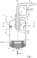
FIG. 1 shows a partially axially cut-away preferred embodiment of a cyclone according to the invention, -
FIG. 2 shows a cross-section of a cyclone according toFIG. 1 seen from above along the marking II--II, -
FIG. 3 shows the inlet opening with its insertion pipes according to the invention,. - In
FIG. 1 , acyclone 1 according to a preferred embodiment according to the invention is shown, in which thecyclone walls 1A themselves are of cylindrical design and the bottom IB and top 1C respectively are designed as cupped gables. Twoinsertion pipes 2', 2" mounted inside a commontubular inlet opening 1E are connected to a common supply source. Via regulatingvalves 4', 4"(seefig.3 ), it is possible to regulate the inflow of gas laden pressurised liquid into thecyclone 1 in an optimum manner.
The gas separated in thecyclone 1 is conducted out through to asteam duct 6 via coaxial outlet pipes 6'and 6", which are arranged in thetop gable 1C. The liquid is conducted out through alower pipe 5. Themouth 2D of the insertion pipes are positioned in such a manner that it opens above thelower end 6A' and 6A" of the outlet pipes 6'and 6" for the separated gas, for the purpose of preventing liquid from being capable of spraying directly into saidinlets 6A' and 6A" in the lower end.
Furthermore, the outercoaxial outlet pipe 6" is preferably provided with acollar 7 in order to prevent drops travelling down along the outside on thepipe 6" and in through the mouth in thelower end 6A".
A further measure for avoiding liquid accompanying the gas flow is the arrangement of an horizontal "anti-swirl plate" 8 which is arranged on radially directed wing shapedvertical pillars 9 directly above the bottom inside the cyclone. Owing to theanti-swirl plate 8 and the wing shaped pillars, the liquid which accumulates in the bottom of the cyclone is prevented from being carried away by the swirl which is formed in the central parts of the cyclone. - In order to further avoid liquid accompanying the gas flow could preferably also a
deflector screen 10 be arranged on the inside of thecyclone wall 1A. Thedeflector screen 10 is of a general "L-shaped" configuration, which opens up downwardly inside the cyclone. Thedeflector screen 10 is arranged at least in the area of theoutlet mouth 2D of theinsertion pipes 2' and 2", covering at least the inner circumferential area from a position X some 10-30 degrees before theoutlet mouth 2D of the insertion pipes 2'and 2", and to a position Y (seefigure 2 ) of at least 45-90 degrees after theoutlet mouth 2D of the insertion pipes 2'and 2", as seen in the circumferential direction. Infigure 2 thedeflector screen 10 is indicated to be arranged over the entire circumference, i.e. 360 degrees. - In the embodiment shown in
figure 1 is also the separated gas from the cyclone directed to at least two flow paths withopenings 6A'and 6A" in thefirst outlet duct 6 from in the cyclone. In order to maintain also a high flow velocity in the outlet from the cyclone for separated gas is the gas outlet including at least 2 outlet pipes 6'and 6" arranged coaxially. The flow in at least oneoutlet pipe 6'and 6" is controlled by a valve member 4'" depending on the order of flow of produced flash steam.
The flow velocity established in each flow path in the outlet duct should preferably also be well above a predetermined critical flow velocity in order to support the strong swirling action within the cyclone.
When the flow velocity is approaching the critical flow velocity is the flow in at least one flow path in the first outlet opening shut off, while maintaining flow in at least one other flow path in the first outlet. The switching of thevalve 4"' between a closed or open position could as shown be made by the same control FC controlling the valves 4'and 4" in the insertion pipes, such that thevalve 4"' is closed simultaneously as one of thevalves 4' or 4" in the insertion pipes is closed. - In
figure 2 is the cyclone seen from above in section I-I infigure 1 . The insertion pipes 2'and 2" are preferably made exchangeable as they are exposed to wear from erosion and also could be replaced with insertion pipes with other dimensions if the typical flow volume handled by the cyclone would dramatically be changed. The insertion pipes 2'and 2" are inserted in atubular inlet duct 1E of the cyclone.
Theinsertion pipes 2' and 2" are preferably both arranged in the same vertical plane, one on top of the other. Bothinsertion pipes 2' and 2" ends preferably at the same insertion depth inside the cyclone and close to a vertical plane lying orthogonally to the direction of thepipes 2' and 2", said vertical plan also intersecting the centre of the cyclone.
Preferably, but not shown, could also a wear plate be mounted on the inside of the cyclone wall in the area of theoutlet mouth 2D of the insertion pipes 2'and 2", such that the flow of liquid that is injected at high speed from themouth 2D impinges on this wear plate and not to the wall of the cyclone. - In
FIG. 3 is theinlet duct 1E seen from left infigure 1 with the the twoinsertion pipes 2' and 2" located on top of each other. According to the invention are control valves 4'and 4" located in the upstream part of eachinsertion pipe 2' and 2". With a simple flow control FC, using a flow sensor FS in the piping from the common source BLPR, is the valves controlled dependent on the order of flow. - As indicated previously, must in many cases a number of series-connected cyclones by used in order to bring down the pressure to or almost to atmospheric level. In each cyclone could the inventive design be implemented.
- The principal control of the flow in the insert pipes is implemented such that the theoretical flow velocity as the liquid exits the
mouth 2D of the inserts pipes exceeds 30 m/s, preferably approximately 40 m/s. This design criteria has proven successful in installations of the prior art flash tank according toUS5,669,948 andUS5,879,422 in most mills operated with less deviation from nominal production capacity. - In a typical flash cyclone for black liquor received from a continuous digester with an output of 900 tonnes/day, is the internal diameter of the cyclone corresponding to 2,5 m and the effective height of about 6 m. The diameter of each single insertion pipe is 140 mm. With a gas laden liquid stream having a pressure which corresponds to 4-5 bar, and a temperature of 152-159°C, an inlet rate corresponding to approximately 40 m/sec is obtained if the pressure in the flash tank is kept at 2,5 bar(g). This is a typical flash tank pressure in a first flash tank in a system with 3 flash tanks in series.
An inlet rate of 40 m/s is also obtained in a cyclone with single insertion pipe having a single insertion pipe with a diameter of 200 mm at these conditions. - In order to achieve effective utilisation of the centrifugal force in order to "break up foam" in cyclones of these dimensions (diameter greater than 1 meter), the inlet rate should exceed 30 m/s, which is the minimum optimum rate. But improved separation of flash steam is gained also at higher inlet rates in the order of 100-400 m/s.
- In a single flash tank system for this order of production could the pressurised gas laden liquid be flashed to a pressure of 0,5 bar inside the flash tank. If a single 200mm inlet pipe, or using twin inlet pipes according the invention with 140 mm diameter each, could an inlet rate of as much as 250 m/s be established.
- In normal steady state operations at the nominal production capacity of the digester is flow in both insertion pipes established. When flow drops below 75% of the nominal production capacity is flow in one of the insertion pipes closed off. The flow rate developed in the remaining insertion pipe will then be maintained well above the critical value. The single activation of one insertion pipe could then maintain a critical flow in the insert pipe well below 50% of the nominal production capacity, and in this example below 40% (about 37%) of the nominal production capacity.
- The invention is not limited by the embodiment shown above but can be varied within the scope of the following patent claims. The expert in the field will consequently understand that the shape of the cyclone could be altered (i.e. conical gables VS cupped gables, and cylindrical casing wall VS conical form). Finally, it should be clarified that the length of the insertion pipes means the part of the insertion pipes which actively functions to recreate an even flow pattern after a relatively great pressure drop (such as after a regulating valve), which part normally means the final part of each insertion pipe. Furthermore, it is obvious for the expert in the field that this final part advantageously has an internal surface which is completely smooth/plane in the direction of flow, in order to counteract the appearance of turbulence/pressure drop.
Claims (10)
- A cyclone (1) for separating a gas from a liquid stream, said cyclone having walls (1A) arranged symmetrically around an axis of of rotation (CC); includinga first end at one end of the axis of rotation, said first end having a first outlet opening (6',6") for gas; andan inlet opening (1E) for said liquid stream oriented in the tangential direction of the axis of rotation (CC) and trough the walls (1A) of the cyclone; anda second outlet (5) for liquid in the second end of the axis of rotation,the inlet opening (1E) having one first insertion pipe (2') having a constant cross-sectional area, a diameter which is less than the diameter of said inlet opening, said insertion pipe adapted for connection to a supply source (BLPR) for said liquid,said first insertion pipe (2') having a first valve member (4') in the upstream end of the insertion pipe as seen from the outlet mouth (2D) of the insertion pipe and having a length of greater than 1 meter between the valve member (4') and the outlet mouth (2D), characterised in that at least one additional insertion pipe (2") is arranged in the inlet opening (1E) and connected to the common supply source (BLPR), and at least one sensor (FS) arranged to detect a parameter representative for the order of flow from the common supply source (BLPR) and said sensor connected to a control member (FC) for controlling the position of the first valve member (4') depending on the order of flow from the common supply source.
- The cyclone of claim 1 characterised in that a second valve member is also arranged (4') in the upstream end of the additional insertion pipe (2") as seen from the outlet mouth (2D) of the additional insertion pipe and having a length of greater than 1 meter between the valve member (4') and the outlet mouth (2D) of the additional insertion pipe.
- The cyclone of claim 2 characterised in that said insertion pipes all have a length of greater than 2 meters between the valve member (4') and the outlet mouth (2D) of each respective insertion pipe (2',2").
- The cyclone of claim 3 characterised in that said insertion pipes all have a length of between about 2.5 and 3.5 meters between the valve member (4') and the outlet mouth (2D) of each respective insertion pipe.
- The cyclone of claim 1 characterised in that said gas outlet (6',6") includes a lower end (6A',6A") within said casing, and wherein said insertion pipe includes an inner end within said casing, said inner end of said insertion pipe being located above said lower end of said gas outlet.
- The cyclone of claim 5 characterised in that said gas outlet includes at least 2 outlet pipes arranged coaxially, the flow in at least one outlet pipe controlled by a third valve member (4"') by a control member (FC) for controlling the position of the third valve member (4"') depending on the order of flow from the common supply source.
- The cyclone of claim 1 characterised in that a deflector screen 10 is arranged on the inside of the cyclone wall 1A, said deflector screen having a general "L-shaped" configuration, which opens up downwardly inside the cyclone, and arranged at least in the area of the outlet mouth (2D) of the insertion pipes (2', 2"), covering at least the inner circumferential area from a position (X) some 10-30 degrees before the outlet mouth (2D) of the insertion pipes (2', 2") and to a position (Y) of at least 45-90 degrees after the outlet mouth 2D of the insertion pipes (2', 2"), as seen in the circumferential direction.
- A method for counteracting foam formation within a cyclone for separating a gas from a gas laden liquid stream having a tendency to foam, said cylone having an inlet for a gas laden liquid stream, and a first outlet opening (6',6") for gas and a second outlet for liquid characterised in that the flow of the gas laden liquid stream from a common source is directed to at least two insertion pipes in the cyclone, establishing a flow velocity in each insertion pipe well above a predetermined critical flow velocity, and when the flow velocity is decreasing and approaching the critical flow velocity is the flow in at least one insertion pipe closed off, while maintaining flow in at least one other insertion pipe.
- The method of claim 8 characterised in that said critical flow rate exceeds 30 meters per second, and preferably above 40 meter per second, and within the range of 30-350 m/s, and preferably within the range of 40-400 m/s.
- The method of claim 8 characterised in that that the flow of the gas from the cyclone is directed to at least two flow paths in the first outlet opening from in the cyclone, establishing a flow velocity in each flow path well above a predetermined critical flow velocity, and when the flow velocity is approaching the critical flow velocity is the flow in at least one flow path in the first outlet opening shut off, while maintaining flow in at least one other flow path in the first outlet.
Applications Claiming Priority (1)
| Application Number | Priority Date | Filing Date | Title |
|---|---|---|---|
| PCT/SE2008/000450 WO2010008325A1 (en) | 2008-07-14 | 2008-07-14 | Cyclone with improved separation of gas from gas laden liquid streams also at reduced flow volumes |
Publications (3)
| Publication Number | Publication Date |
|---|---|
| EP2313203A1 EP2313203A1 (en) | 2011-04-27 |
| EP2313203A4 EP2313203A4 (en) | 2017-04-26 |
| EP2313203B1 true EP2313203B1 (en) | 2018-04-18 |
Family
ID=41550553
Family Applications (1)
| Application Number | Title | Priority Date | Filing Date |
|---|---|---|---|
| EP08767113.7A Not-in-force EP2313203B1 (en) | 2008-07-14 | 2008-07-14 | Cyclone with improved separation of gas from gas laden liquid streams also at reduced flow volumes |
Country Status (3)
| Country | Link |
|---|---|
| US (1) | US8366802B2 (en) |
| EP (1) | EP2313203B1 (en) |
| WO (1) | WO2010008325A1 (en) |
Families Citing this family (10)
| Publication number | Priority date | Publication date | Assignee | Title |
|---|---|---|---|---|
| WO2010101459A1 (en) * | 2009-03-02 | 2010-09-10 | Convex B.V. | Apparatus and method for purifying a liquid |
| US8877012B2 (en) * | 2012-10-24 | 2014-11-04 | Andritz Inc. | Piping system from reactor to separator and method to control process flow |
| CA2844330C (en) | 2013-02-25 | 2019-10-15 | Bruce Lyon | Sand separator |
| US9265267B2 (en) | 2013-07-22 | 2016-02-23 | Garry Parkinson Isaacs | Open top liquid/gas cyclone separator tube and process for same |
| KR101701280B1 (en) * | 2015-10-06 | 2017-02-13 | 두산중공업 주식회사 | Cyclone type liquid-vapor separator and forced circulation type evaporator using the same |
| NO343290B1 (en) * | 2015-11-09 | 2019-01-21 | Fmc Kongsberg Subsea As | Solids separator |
| SE542043C2 (en) * | 2018-05-03 | 2020-02-18 | Valmet Oy | System and method for treatment of a biomass material, a transporting pipe, and a gas separation system |
| WO2020028815A1 (en) * | 2018-08-03 | 2020-02-06 | EnerSysNet U.S. Holdings, Inc. | Biomass processing devices, systems, and methods |
| FI130019B (en) * | 2018-10-22 | 2022-12-30 | Maricap Oy | Method for handling material in a material transport system, separator arrangement and material transport system |
| CN224156406U (en) * | 2022-05-12 | 2026-04-24 | 卡莱菲公司 | Device for separating gas from vector fluid in circuit of thermal system |
Family Cites Families (14)
| Publication number | Priority date | Publication date | Assignee | Title |
|---|---|---|---|---|
| NL63590C (en) * | 1941-07-15 | |||
| US3163508A (en) * | 1960-09-07 | 1964-12-29 | Smith Paper Mills Ltd Howard | Method and apparatus for separating gas from liquid rich foams or liquids containing entrained air |
| DE1301796B (en) * | 1967-06-13 | 1969-08-28 | Grubbens & Co Aktiebolag | Hydrocyclone |
| DE2137128C3 (en) * | 1971-07-24 | 1978-10-05 | Siemens Ag, 1000 Berlin Und 8000 Muenchen | Device for generating swirl in a rotary flow vortex |
| SE407751B (en) * | 1976-03-26 | 1979-04-23 | Celleco Ab | DEVICE FOR A HYDROCYCLONE |
| US4225325A (en) * | 1979-06-14 | 1980-09-30 | W-K-M Wellhead Systems, Inc. | Steam separator with variably sized rectangular inlet opening |
| JPS60501546A (en) * | 1983-06-01 | 1985-09-19 | コノコ スペシャルティ プロダクツ インコーポレイティド | Overflow outlet for cyclone separator |
| US4795561A (en) * | 1987-01-23 | 1989-01-03 | Aeroquip Corporation | Self regulating cyclonic separator |
| US4969934A (en) * | 1989-08-04 | 1990-11-13 | The United States Of America As Represented By The United States Department Of Energy | Method for improved gas-solids separation |
| SE508561C2 (en) * | 1991-07-16 | 1998-10-12 | Kvaerner Pulping Tech | Method and apparatus for separating particles from a gas stream |
| SE9103824L (en) * | 1991-12-23 | 1992-11-30 | Kamyr Ab | SETTING AND CYCLONING DEVICE TO DISABLE Foam Formation |
| FI107435B (en) * | 1996-11-19 | 2001-08-15 | Foster Wheeler Energia Oy | Centrifugal separator device and process for separating particles from hot gas of a fluidized bed reactor |
| AU5849100A (en) * | 1999-07-05 | 2001-01-22 | Kabushiki Kaisha Yokota Seisakusho | Pump device |
| US6993857B2 (en) * | 2000-08-29 | 2006-02-07 | Eco Technology International (2000) Limited | Milling and drying apparatus incorporating a cyclone |
-
2008
- 2008-07-14 WO PCT/SE2008/000450 patent/WO2010008325A1/en not_active Ceased
- 2008-07-14 US US13/002,653 patent/US8366802B2/en not_active Expired - Fee Related
- 2008-07-14 EP EP08767113.7A patent/EP2313203B1/en not_active Not-in-force
Non-Patent Citations (1)
| Title |
|---|
| None * |
Also Published As
| Publication number | Publication date |
|---|---|
| WO2010008325A1 (en) | 2010-01-21 |
| US20110185894A1 (en) | 2011-08-04 |
| US8366802B2 (en) | 2013-02-05 |
| EP2313203A1 (en) | 2011-04-27 |
| EP2313203A4 (en) | 2017-04-26 |
Similar Documents
| Publication | Publication Date | Title |
|---|---|---|
| US8366802B2 (en) | Cyclone with improved separation of gas from gas laden liquid streams also at reduced flow volumes | |
| US5879422A (en) | Separating arrangement and method for counteracting foam formation | |
| EP2528690B1 (en) | System comprising centrifugal separator and method for controlling such a system | |
| US4876016A (en) | Method of controlling the separation efficiency of a hydrocyclone | |
| EP2414067B1 (en) | Device for separating into fractions a fluid comprising several fractions with double separation | |
| JPS607923B2 (en) | Apparatus and method for separating gas from fiber suspension | |
| US6402820B1 (en) | Fluidic level control systems | |
| GB1589347A (en) | Hydrocyclone separator arrangement | |
| JPS61225390A (en) | Refining apparatus, especially, deinking apparatus for paperpulp | |
| CN114712945A (en) | Sand removing device | |
| US7452444B2 (en) | Digester wash extraction by individual screen flow control | |
| FI123014B (en) | Structure of bottom diluent in a cyclone cleaner, and process in a structure of bottom diluent in a cyclone cleaner | |
| FI126305B (en) | Variable cross section black liquor nozzle and method for burning black liquor | |
| CN220860870U (en) | Concentrating device | |
| US20110203755A1 (en) | Method for preventing clogging in a strainer construction for a continuous digester | |
| CN117085396A (en) | Concentration device and concentration method | |
| CN206706453U (en) | Waste paper pulp-making desanding system | |
| AU658948B2 (en) | Liquid reservoir | |
| CN108126366A (en) | A kind of improved next door tower gas phase distribution ratio regulating device | |
| US6923329B2 (en) | Screen apparatus | |
| CN106076440A (en) | Ion exchanger | |
| CN207064815U (en) | A kind of stop valve for gas | |
| CN205115908U (en) | Novel pipeline connecting structure of paper machine pressurized screen | |
| FI122972B (en) | Device for distributing a mass flow | |
| FI108652B (en) | Procedures and devices for controlling short circulation in a paper, cardboard or similar production machine |
Legal Events
| Date | Code | Title | Description |
|---|---|---|---|
| PUAI | Public reference made under article 153(3) epc to a published international application that has entered the european phase |
Free format text: ORIGINAL CODE: 0009012 |
|
| 17P | Request for examination filed |
Effective date: 20110214 |
|
| AK | Designated contracting states |
Kind code of ref document: A1 Designated state(s): AT BE BG CH CY CZ DE DK EE ES FI FR GB GR HR HU IE IS IT LI LT LU LV MC MT NL NO PL PT RO SE SI SK TR |
|
| AX | Request for extension of the european patent |
Extension state: AL BA MK RS |
|
| DAX | Request for extension of the european patent (deleted) | ||
| RAP1 | Party data changed (applicant data changed or rights of an application transferred) |
Owner name: METSO PAPER SWEDEN AKTIEBOLAG |
|
| RAP1 | Party data changed (applicant data changed or rights of an application transferred) |
Owner name: VALMET AKTIEBOLAG |
|
| RA4 | Supplementary search report drawn up and despatched (corrected) |
Effective date: 20170327 |
|
| RIC1 | Information provided on ipc code assigned before grant |
Ipc: B01D 19/00 20060101ALI20170321BHEP Ipc: B04C 5/04 20060101AFI20170321BHEP Ipc: B04C 11/00 20060101ALI20170321BHEP Ipc: B04C 5/13 20060101ALI20170321BHEP |
|
| GRAP | Despatch of communication of intention to grant a patent |
Free format text: ORIGINAL CODE: EPIDOSNIGR1 |
|
| STAA | Information on the status of an ep patent application or granted ep patent |
Free format text: STATUS: GRANT OF PATENT IS INTENDED |
|
| RIC1 | Information provided on ipc code assigned before grant |
Ipc: B04C 5/13 20060101ALI20171016BHEP Ipc: B04C 5/04 20060101AFI20171016BHEP Ipc: B01D 19/00 20060101ALI20171016BHEP Ipc: B04C 11/00 20060101ALI20171016BHEP |
|
| INTG | Intention to grant announced |
Effective date: 20171114 |
|
| GRAS | Grant fee paid |
Free format text: ORIGINAL CODE: EPIDOSNIGR3 |
|
| GRAA | (expected) grant |
Free format text: ORIGINAL CODE: 0009210 |
|
| STAA | Information on the status of an ep patent application or granted ep patent |
Free format text: STATUS: THE PATENT HAS BEEN GRANTED |
|
| AK | Designated contracting states |
Kind code of ref document: B1 Designated state(s): AT BE BG CH CY CZ DE DK EE ES FI FR GB GR HR HU IE IS IT LI LT LU LV MC MT NL NO PL PT RO SE SI SK TR |
|
| REG | Reference to a national code |
Ref country code: GB Ref legal event code: FG4D |
|
| REG | Reference to a national code |
Ref country code: CH Ref legal event code: EP |
|
| REG | Reference to a national code |
Ref country code: DE Ref legal event code: R096 Ref document number: 602008054898 Country of ref document: DE |
|
| REG | Reference to a national code |
Ref country code: AT Ref legal event code: REF Ref document number: 989868 Country of ref document: AT Kind code of ref document: T Effective date: 20180515 |
|
| REG | Reference to a national code |
Ref country code: IE Ref legal event code: FG4D |
|
| REG | Reference to a national code |
Ref country code: NL Ref legal event code: MP Effective date: 20180418 |
|
| REG | Reference to a national code |
Ref country code: LT Ref legal event code: MG4D |
|
| PG25 | Lapsed in a contracting state [announced via postgrant information from national office to epo] |
Ref country code: NL Free format text: LAPSE BECAUSE OF FAILURE TO SUBMIT A TRANSLATION OF THE DESCRIPTION OR TO PAY THE FEE WITHIN THE PRESCRIBED TIME-LIMIT Effective date: 20180418 |
|
| PG25 | Lapsed in a contracting state [announced via postgrant information from national office to epo] |
Ref country code: ES Free format text: LAPSE BECAUSE OF FAILURE TO SUBMIT A TRANSLATION OF THE DESCRIPTION OR TO PAY THE FEE WITHIN THE PRESCRIBED TIME-LIMIT Effective date: 20180418 Ref country code: PL Free format text: LAPSE BECAUSE OF FAILURE TO SUBMIT A TRANSLATION OF THE DESCRIPTION OR TO PAY THE FEE WITHIN THE PRESCRIBED TIME-LIMIT Effective date: 20180418 Ref country code: SE Free format text: LAPSE BECAUSE OF FAILURE TO SUBMIT A TRANSLATION OF THE DESCRIPTION OR TO PAY THE FEE WITHIN THE PRESCRIBED TIME-LIMIT Effective date: 20180418 Ref country code: NO Free format text: LAPSE BECAUSE OF FAILURE TO SUBMIT A TRANSLATION OF THE DESCRIPTION OR TO PAY THE FEE WITHIN THE PRESCRIBED TIME-LIMIT Effective date: 20180718 Ref country code: BG Free format text: LAPSE BECAUSE OF FAILURE TO SUBMIT A TRANSLATION OF THE DESCRIPTION OR TO PAY THE FEE WITHIN THE PRESCRIBED TIME-LIMIT Effective date: 20180718 Ref country code: LT Free format text: LAPSE BECAUSE OF FAILURE TO SUBMIT A TRANSLATION OF THE DESCRIPTION OR TO PAY THE FEE WITHIN THE PRESCRIBED TIME-LIMIT Effective date: 20180418 |
|
| PG25 | Lapsed in a contracting state [announced via postgrant information from national office to epo] |
Ref country code: GR Free format text: LAPSE BECAUSE OF FAILURE TO SUBMIT A TRANSLATION OF THE DESCRIPTION OR TO PAY THE FEE WITHIN THE PRESCRIBED TIME-LIMIT Effective date: 20180719 Ref country code: LV Free format text: LAPSE BECAUSE OF FAILURE TO SUBMIT A TRANSLATION OF THE DESCRIPTION OR TO PAY THE FEE WITHIN THE PRESCRIBED TIME-LIMIT Effective date: 20180418 Ref country code: HR Free format text: LAPSE BECAUSE OF FAILURE TO SUBMIT A TRANSLATION OF THE DESCRIPTION OR TO PAY THE FEE WITHIN THE PRESCRIBED TIME-LIMIT Effective date: 20180418 |
|
| PG25 | Lapsed in a contracting state [announced via postgrant information from national office to epo] |
Ref country code: PT Free format text: LAPSE BECAUSE OF FAILURE TO SUBMIT A TRANSLATION OF THE DESCRIPTION OR TO PAY THE FEE WITHIN THE PRESCRIBED TIME-LIMIT Effective date: 20180820 |
|
| REG | Reference to a national code |
Ref country code: DE Ref legal event code: R097 Ref document number: 602008054898 Country of ref document: DE |
|
| PG25 | Lapsed in a contracting state [announced via postgrant information from national office to epo] |
Ref country code: RO Free format text: LAPSE BECAUSE OF FAILURE TO SUBMIT A TRANSLATION OF THE DESCRIPTION OR TO PAY THE FEE WITHIN THE PRESCRIBED TIME-LIMIT Effective date: 20180418 Ref country code: CZ Free format text: LAPSE BECAUSE OF FAILURE TO SUBMIT A TRANSLATION OF THE DESCRIPTION OR TO PAY THE FEE WITHIN THE PRESCRIBED TIME-LIMIT Effective date: 20180418 Ref country code: EE Free format text: LAPSE BECAUSE OF FAILURE TO SUBMIT A TRANSLATION OF THE DESCRIPTION OR TO PAY THE FEE WITHIN THE PRESCRIBED TIME-LIMIT Effective date: 20180418 Ref country code: DK Free format text: LAPSE BECAUSE OF FAILURE TO SUBMIT A TRANSLATION OF THE DESCRIPTION OR TO PAY THE FEE WITHIN THE PRESCRIBED TIME-LIMIT Effective date: 20180418 Ref country code: SK Free format text: LAPSE BECAUSE OF FAILURE TO SUBMIT A TRANSLATION OF THE DESCRIPTION OR TO PAY THE FEE WITHIN THE PRESCRIBED TIME-LIMIT Effective date: 20180418 |
|
| REG | Reference to a national code |
Ref country code: DE Ref legal event code: R119 Ref document number: 602008054898 Country of ref document: DE |
|
| PLBE | No opposition filed within time limit |
Free format text: ORIGINAL CODE: 0009261 |
|
| STAA | Information on the status of an ep patent application or granted ep patent |
Free format text: STATUS: NO OPPOSITION FILED WITHIN TIME LIMIT |
|
| PG25 | Lapsed in a contracting state [announced via postgrant information from national office to epo] |
Ref country code: IT Free format text: LAPSE BECAUSE OF FAILURE TO SUBMIT A TRANSLATION OF THE DESCRIPTION OR TO PAY THE FEE WITHIN THE PRESCRIBED TIME-LIMIT Effective date: 20180418 |
|
| REG | Reference to a national code |
Ref country code: CH Ref legal event code: PL |
|
| 26N | No opposition filed |
Effective date: 20190121 |
|
| GBPC | Gb: european patent ceased through non-payment of renewal fee |
Effective date: 20180718 |
|
| PG25 | Lapsed in a contracting state [announced via postgrant information from national office to epo] |
Ref country code: MC Free format text: LAPSE BECAUSE OF FAILURE TO SUBMIT A TRANSLATION OF THE DESCRIPTION OR TO PAY THE FEE WITHIN THE PRESCRIBED TIME-LIMIT Effective date: 20180418 Ref country code: LU Free format text: LAPSE BECAUSE OF NON-PAYMENT OF DUE FEES Effective date: 20180714 |
|
| REG | Reference to a national code |
Ref country code: BE Ref legal event code: MM Effective date: 20180731 |
|
| REG | Reference to a national code |
Ref country code: IE Ref legal event code: MM4A |
|
| PG25 | Lapsed in a contracting state [announced via postgrant information from national office to epo] |
Ref country code: GB Free format text: LAPSE BECAUSE OF NON-PAYMENT OF DUE FEES Effective date: 20180718 Ref country code: DE Free format text: LAPSE BECAUSE OF NON-PAYMENT OF DUE FEES Effective date: 20190201 Ref country code: CH Free format text: LAPSE BECAUSE OF NON-PAYMENT OF DUE FEES Effective date: 20180731 Ref country code: LI Free format text: LAPSE BECAUSE OF NON-PAYMENT OF DUE FEES Effective date: 20180731 Ref country code: FR Free format text: LAPSE BECAUSE OF NON-PAYMENT OF DUE FEES Effective date: 20180731 Ref country code: IE Free format text: LAPSE BECAUSE OF NON-PAYMENT OF DUE FEES Effective date: 20180714 |
|
| PG25 | Lapsed in a contracting state [announced via postgrant information from national office to epo] |
Ref country code: SI Free format text: LAPSE BECAUSE OF FAILURE TO SUBMIT A TRANSLATION OF THE DESCRIPTION OR TO PAY THE FEE WITHIN THE PRESCRIBED TIME-LIMIT Effective date: 20180418 Ref country code: BE Free format text: LAPSE BECAUSE OF NON-PAYMENT OF DUE FEES Effective date: 20180731 |
|
| PGFP | Annual fee paid to national office [announced via postgrant information from national office to epo] |
Ref country code: FI Payment date: 20190722 Year of fee payment: 12 |
|
| PGFP | Annual fee paid to national office [announced via postgrant information from national office to epo] |
Ref country code: AT Payment date: 20190722 Year of fee payment: 12 |
|
| PG25 | Lapsed in a contracting state [announced via postgrant information from national office to epo] |
Ref country code: MT Free format text: LAPSE BECAUSE OF NON-PAYMENT OF DUE FEES Effective date: 20180714 |
|
| PG25 | Lapsed in a contracting state [announced via postgrant information from national office to epo] |
Ref country code: TR Free format text: LAPSE BECAUSE OF FAILURE TO SUBMIT A TRANSLATION OF THE DESCRIPTION OR TO PAY THE FEE WITHIN THE PRESCRIBED TIME-LIMIT Effective date: 20180418 |
|
| PG25 | Lapsed in a contracting state [announced via postgrant information from national office to epo] |
Ref country code: HU Free format text: LAPSE BECAUSE OF FAILURE TO SUBMIT A TRANSLATION OF THE DESCRIPTION OR TO PAY THE FEE WITHIN THE PRESCRIBED TIME-LIMIT; INVALID AB INITIO Effective date: 20080714 |
|
| PG25 | Lapsed in a contracting state [announced via postgrant information from national office to epo] |
Ref country code: CY Free format text: LAPSE BECAUSE OF FAILURE TO SUBMIT A TRANSLATION OF THE DESCRIPTION OR TO PAY THE FEE WITHIN THE PRESCRIBED TIME-LIMIT Effective date: 20180418 |
|
| PG25 | Lapsed in a contracting state [announced via postgrant information from national office to epo] |
Ref country code: IS Free format text: LAPSE BECAUSE OF FAILURE TO SUBMIT A TRANSLATION OF THE DESCRIPTION OR TO PAY THE FEE WITHIN THE PRESCRIBED TIME-LIMIT Effective date: 20180818 |
|
| REG | Reference to a national code |
Ref country code: FI Ref legal event code: MAE |
|
| REG | Reference to a national code |
Ref country code: AT Ref legal event code: MM01 Ref document number: 989868 Country of ref document: AT Kind code of ref document: T Effective date: 20200714 |
|
| REG | Reference to a national code |
Ref country code: AT Ref legal event code: UEP Ref document number: 989868 Country of ref document: AT Kind code of ref document: T Effective date: 20180418 |
|
| PG25 | Lapsed in a contracting state [announced via postgrant information from national office to epo] |
Ref country code: FI Free format text: LAPSE BECAUSE OF NON-PAYMENT OF DUE FEES Effective date: 20200714 |
|
| PG25 | Lapsed in a contracting state [announced via postgrant information from national office to epo] |
Ref country code: AT Free format text: LAPSE BECAUSE OF NON-PAYMENT OF DUE FEES Effective date: 20200714 |