EP2313001B1 - Method and device using shortened square wave waveforms in synchronous signal processing - Google Patents
Method and device using shortened square wave waveforms in synchronous signal processing Download PDFInfo
- Publication number
- EP2313001B1 EP2313001B1 EP20090745476 EP09745476A EP2313001B1 EP 2313001 B1 EP2313001 B1 EP 2313001B1 EP 20090745476 EP20090745476 EP 20090745476 EP 09745476 A EP09745476 A EP 09745476A EP 2313001 B1 EP2313001 B1 EP 2313001B1
- Authority
- EP
- European Patent Office
- Prior art keywords
- rectangular
- signal
- modified
- shortened
- subsignal
- Prior art date
- Legal status (The legal status is an assumption and is not a legal conclusion. Google has not performed a legal analysis and makes no representation as to the accuracy of the status listed.)
- Not-in-force
Links
Images



Classifications
-
- A—HUMAN NECESSITIES
- A61—MEDICAL OR VETERINARY SCIENCE; HYGIENE
- A61B—DIAGNOSIS; SURGERY; IDENTIFICATION
- A61B5/00—Measuring for diagnostic purposes; Identification of persons
- A61B5/05—Detecting, measuring or recording for diagnosis by means of electric currents or magnetic fields; Measuring using microwaves or radio waves
- A61B5/053—Measuring electrical impedance or conductance of a portion of the body
Definitions
- the invention relates to methods of synchronous signal processing using shortened square wave waveforms.
- the method is particularly suitable for impedance measurements, e.g., of bioobjects such as tissues, organs, muscles, etc.
- Impedance measurements are widely used for characterizing parameters of materials and substances, tissue parameters in biology and medicine, and even cell cultures [1].
- electrical impedance is often called electrical bioimpedance (EBI) [2]. It could be measured at several different frequencies (multifrequency measurements), and sometimes also from multiple locations (multisite measurements) in order to derive multidimensional picture of tissue parameters under examination.
- EBI in many cases together with visual inspection, temperature measurements etc. gives valuable information, useful in formulating a diagnosis and providing proper medical care to the patient. It can be used for monitoring human heart functionality in pacemakers, during surgery, or for restoring normal blood flow after surgery. These measurements are usually conducted using synchronous signal processing.
- sinusoidal signals instead of the sinusoidal signals, other waveforms can be used, provided that correlation between measurement results with sinusoidal signals can be shown with acceptable accuracy and repeatability.
- square wave excitation [3] can be used mainly because it is energy efficient, easy to generate, and easy to process. Substantial energy savings can be achieved at higher level of reliability (corresponds to reduced number of components).
- higher harmonics of non-sinusoidal waveforms cause errors, which need to be dealt with, or ideally suppressed [4].
- Well-known solution is band pass filtering of the excitations signal [5].
- good results can be achieved by using different piecewise continuous approximations of sinusoidal signals [6].
- Drawback associated with later approach is that harmonics content is very sensitive to level accuracy, and usually needs adjustments.
- Random and pseudo-random binary sequences are investigated, and maximum length sequences (MLS) are reported to give good results for high-speed impedance measurement of small particles in microfluidic cytometer [7].
- MLS maximum length sequences
- FMT fast M-sequence transform
- FFT fast M-sequence transform
- Synchronous demodulation is sensitive only to higher harmonics, which are existing simultaneously in both, the excitation and reference signals, such as the 7th, 11th, 13the, 17th, 19th, 23rd, 29th, and 31th in case of 30°/18° shortened signals.
- Fig. 3A Impact of higher harmonics of the excitation and reference signals to the multiplication result in case of 30°/18° shortened signals can be seen in Fig. 3A .
- impact of the 5 th , 9 th , 15 th , 21 st , 25 th , and 27 th higher harmonics is absent.
- Fig. 3B is introduced for comparison with using of simple square waves.
- the objective of the invention is a method for impedance measurements comprising introducing a first modified rectangular signal into an object such as bioobject, e.g., a tissue, receiving a response signal from said object, introducing said response signal and a second modified rectangular signal into a synchronous detector, whereas either said first modified rectangular signal or said second modified rectangular signal, or both signals are so modified as to remove certain higher harmonics from the signals.
- Fig. 3 depicts the principal set up where the invented method can be used.
- An excitation signal 1 is introduced into an object 2 such as bioobject, for example, a tissue.
- the excitation signal 2 can be any periodic signal with known frequency and harmonic content, such as sinusoidal signal, triangular signal, a rectangular signal that is modified as known from the art, e.g., as shown in FIG 1B , or any of the modified rectangular signals according to this invention (see Figs 5 and 7 ).
- a response signal 3, corresponding to the excitation signal 1 is then received from the object 2 and introduced into synchronous detecting means 6, such as a synchronous detector.
- Synchronous detector 6 is used, e.g., for inphase signal and detector 7 for quadrature channel.
- a reference signal 4 (for inphase channel; reference signal 5 for quadrature channel) is also introduced into the synchronous detector.
- the reference signal is a modified rectangular signal according to this invention. "Modified rectangular signal" can be best described comparing to traditional rectangular signal.
- the traditional rectangular signal has amplitude A and period T so that the signal has value A during one of the half periods T/2 and value -A during the other half period T/2.
- the modified rectangular signal also has period T and amplitude A. However, each half period of the modified rectangular signal comprises zero amplitude segments ( ⁇ ⁇ 0°), i.e., segments during which the value of the signal is zero.
- Such signal has a harmonic content improved compared to traditional rectangular signal in that at least one higher harmonic is at least partially suppressed.
- Such signal has zero value during first 18° segment, value A (e.g., unit value 1) during following 12° segment, zero value during the yet following 12° segment, value A during the next 96° segment, then zero value for 12° segment, value A for 12° segment and zero value during the last 18° segment of the half period T/2.
- value A e.g., unit value 1
- the second half period is symmetrical to the first half period, having value -A instead of value A.
- Such the signal can be easily generated by summing up three signals - the signals having the same shape as the signals Vref and Vexc shown in Fig. 2 , and a third signal that is shortened similarly by 42° at the beginning and end of each half period. It appears that when summing 18° shortened signal with + sign, 30° shortened signal with - sign, and 42° shortened signal with + sign, the new waveform ( Fig 5A ) is free from both the 3rd and 5th harmonics. Resulting spectrum of such signal can be seen in Fig. 5B .
- the excitation signal 1 is a first modified rectangular signal, having improved harmonic content.
- Such excitation signal 1 is formed by adding three subsignals 101, 102 and 103 by summing means 13 (see Fig 3A ).
- the subsignals and corresponding excitation signal 1 are shown in Fig. 7A and the spectrum of this signal is shown in Fig. 6A .
- the reference signal 4 to be introduced into synchronous detector 6 is generated by adding three subsignals 401, 402 and 403 by summing means 14 (see Fig 3C ).
- the subsignals and corresponding reference signal is shown in Fig 7B and the spectrum of this signal is depicted in Fig 6B .
- Fig. 7A is more preferred as excitation signal as it has higher excitation energy, in principle, also the signal shown in Fig. 7B used as the excitation signal and signal shown in Fig. 7A as the reference signal.
- a set up according to Fig. 3D can be used for generating the reference signal. Instead of first summing up the subsignals 401 to 403, first the subsignals are introduced into synchronous detectors 61 to 63 respectively, and then the resulting signals are summed in summing means 15.
- the excitation signal is a rectangular signal, or alternatively, a modified rectangular signal know from the art.
- Our invention improves the measurement results considerably also in the case when one of the used two signals is a traditional rectangular one, but the other is modified according to the embodiment of our invention.
- the most preferable modified signal is given in FIG. 5A , the spectrum of which does not contain the 3 rd and the 5 th higher harmonics. As a result, the impact of these higher harmonics is absent.
- EXAMPLE 3 According to the third embodiment, a sinusoidal excitation signal is used. Our invention improves the signal-to-noise ratio and gives more exact measurement results even then, when the excitation signal is a traditional sine wave. The embodiment of improvement is based on the fact that zero value state of the reference signal impedes both the response signal and accompanied noise. When the noise level is high then the segment of impeded noise can be higher than the segment of sine wave.
- the most reasonable modified signal is a simple modification of the signal shown in Fig 2 with the zero state segment is not 18° or 30° but preferably 22.5°, which value 360°/16 is very near to the mathematical optimum is 21.4°
Landscapes
- Health & Medical Sciences (AREA)
- Life Sciences & Earth Sciences (AREA)
- Medical Informatics (AREA)
- Molecular Biology (AREA)
- Radiology & Medical Imaging (AREA)
- Biophysics (AREA)
- Pathology (AREA)
- Engineering & Computer Science (AREA)
- Biomedical Technology (AREA)
- Heart & Thoracic Surgery (AREA)
- Nuclear Medicine, Radiotherapy & Molecular Imaging (AREA)
- Physics & Mathematics (AREA)
- Surgery (AREA)
- Animal Behavior & Ethology (AREA)
- General Health & Medical Sciences (AREA)
- Public Health (AREA)
- Veterinary Medicine (AREA)
- Measuring Pulse, Heart Rate, Blood Pressure Or Blood Flow (AREA)
- Measurement And Recording Of Electrical Phenomena And Electrical Characteristics Of The Living Body (AREA)
- Investigating Or Analyzing Materials By The Use Of Electric Means (AREA)
Abstract
Description
- The invention relates to methods of synchronous signal processing using shortened square wave waveforms. The method is particularly suitable for impedance measurements, e.g., of bioobjects such as tissues, organs, muscles, etc.
- Impedance measurements are widely used for characterizing parameters of materials and substances, tissue parameters in biology and medicine, and even cell cultures [1]. When characterizing biological and medical parameters of tissue segments, electrical impedance is often called electrical bioimpedance (EBI) [2]. It could be measured at several different frequencies (multifrequency measurements), and sometimes also from multiple locations (multisite measurements) in order to derive multidimensional picture of tissue parameters under examination. EBI (in many cases together with visual inspection, temperature measurements etc.) gives valuable information, useful in formulating a diagnosis and providing proper medical care to the patient. It can be used for monitoring human heart functionality in pacemakers, during surgery, or for restoring normal blood flow after surgery. These measurements are usually conducted using synchronous signal processing. Same method enables measurement of low-level signals with lock-in amplifiers, and is used in different network analyzers. Classically sinusoidal excitation is used, and Fast Fourier Transformation (FFT) or similar is used for spectral separation. It enables determination of magnitude and phase of the response signal compared to the excitation signal, and gives relatively good results, depending on the quality of the excitation signal and signal processing algorithms. Typical signal chain for synchronous measurements is shown on
Fig. 1 , in which sine wave signals are used classically. Summing stage could be omitted, however in some circumstances compensation could improve resolution of the result. For out of the body applications size and energy consumption are not necessarily important, even though it is generally desirable to keep the energy consumption at minimum. Situation changes dramatically in case of implantable devices, such as pacemakers. Both analog circuitry and digital signal processing tend to consume a lot of energy. Also, size of the device should be kept as small as possible. - Instead of the sinusoidal signals, other waveforms can be used, provided that correlation between measurement results with sinusoidal signals can be shown with acceptable accuracy and repeatability. In wearable and implantable devices square wave excitation [3] can be used mainly because it is energy efficient, easy to generate, and easy to process. Substantial energy savings can be achieved at higher level of reliability (corresponds to reduced number of components). However, higher harmonics of non-sinusoidal waveforms cause errors, which need to be dealt with, or ideally suppressed [4]. Well-known solution is band pass filtering of the excitations signal [5]. Alternatively good results can be achieved by using different piecewise continuous approximations of sinusoidal signals [6]. Drawback associated with later approach is that harmonics content is very sensitive to level accuracy, and usually needs adjustments. Random and pseudo-random binary sequences are investigated, and maximum length sequences (MLS) are reported to give good results for high-speed impedance measurement of small particles in microfluidic cytometer [7]. Unfortunately it also involves rather complex signal processing at later stage including fast M-sequence transform (FMT), as well as FFT, before impedance information can be determined
- Systematic errors introduced by higher harmonics of simple square wave signals can be drastically reduced by modifying the rectangular waveforms [8]. In case of shortening each rectangular half period of the excitation and reference signals by 30° and 18° correspondingly by introducing a section with zero amplitude at each end of the half period of the signals (see
Fig. 2 ) the errors from higher odd harmonics can be reduced more than order of magnitude in comparison with regular rectangular waves. - Spectra of these signals can be expressed as the Fourier series of odd harmonics:

- for the 3rd harmonic 3·β = π/2 must be fulfilled, which means that β = 30°
- for the 5th harmonic 5·β = π/2 must be fulfilled, which shows that β = 18°.
- Synchronous demodulation is sensitive only to higher harmonics, which are existing simultaneously in both, the excitation and reference signals, such as the 7th, 11th, 13the, 17th, 19th, 23rd, 29th, and 31th in case of 30°/18° shortened signals.
- In some cases, these simultaneously existing higher harmonics have negligible effect on measurement accuracy. Impact of higher harmonics of the excitation and reference signals to the multiplication result in case of 30°/18° shortened signals can be seen in
Fig. 3A . As a result, impact of the 5th, 9th, 15th, 21st, 25th, and 27th higher harmonics is absent.Fig. 3B is introduced for comparison with using of simple square waves. - However, there is a need for for higher accuracy than the prior art can offer. For example, the impact of the 7th harmonic has remained too substantial for providing precision measurements.
- The objective of the invention is a method for impedance measurements comprising introducing a first modified rectangular signal into an object such as bioobject, e.g., a tissue, receiving a response signal from said object, introducing said response signal and a second modified rectangular signal into a synchronous detector, whereas either said first modified rectangular signal or said second modified rectangular signal, or both signals are so modified as to remove certain higher harmonics from the signals.
-
-
Fig. 1 is a typical signal chain for synchronous measurements of impedance, where sinusoidal signals are traditionally used; -
Fig. 2 depicts modified rectangular wave waveforms to be used in a set up ofFig 1 instead of sinusoidal signals, wherein the rectangular half periods of rectangular wave waveforms are shortened at each end by 18° and 30° respectively; -
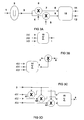
Fig. 3A depicts the system where the invented method can be used.Fig 3B illustrates generating the excitation signal according to the invention.Fig. 3C illustrates generating a reference signal according to the invention.Fig. 3D illustrates alternative set up for generating reference signal. -
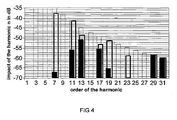
Fig. 4 comparatively show the higher harmonics present in different waveforms at the exit of the synchronous detector: 18°/30° shortened signal pair ofFig. 2 (white columns), an ordinary 50/50 duty cycle rectangular wave (dotted lines) and for signals shown inFigs 7A and 7B (black columns) -
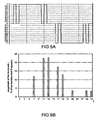
Fig. 5 depicts a modified rectangular wave signal, generated by summing three modified rectangular wave waveforms, shortened by 18°, 30° and 42° respectively (Fig 5A ) and resulting spectral composition (Fig 5B ); -
Fig. 6 depicts a spectral view of modified rectangular wave waveforms, generated by summing three modified rectangular signals with addingcoefficients 1, -0.5 and 0.5 (Fig 6A ) and withcoefficients Fig 6B ); -
Fig. 7 depicts a half periods of waveforms with addingcoefficients 1, -0.5 and 0.5 (Fig 7A ) and withcoefficients Fig 7B ); - The invention is now described with references to enclosed figures.
-
Fig. 3 depicts the principal set up where the invented method can be used. Anexcitation signal 1 is introduced into anobject 2 such as bioobject, for example, a tissue. Theexcitation signal 2 can be any periodic signal with known frequency and harmonic content, such as sinusoidal signal, triangular signal, a rectangular signal that is modified as known from the art, e.g., as shown inFIG 1B , or any of the modified rectangular signals according to this invention (seeFigs 5 and7 ). - A
response signal 3, corresponding to theexcitation signal 1 is then received from theobject 2 and introduced into synchronous detectingmeans 6, such as a synchronous detector.Synchronous detector 6 is used, e.g., for inphase signal anddetector 7 for quadrature channel. A reference signal 4 (for inphase channel;reference signal 5 for quadrature channel) is also introduced into the synchronous detector. The reference signal is a modified rectangular signal according to this invention. "Modified rectangular signal" can be best described comparing to traditional rectangular signal. The traditional rectangular signal has amplitude A and period T so that the signal has value A during one of the half periods T/2 and value -A during the other half period T/2. Such signal has harmonic content represented by equation (1) above in the case, where the zero state is absent (β = 0°). The modified rectangular signal also has period T and amplitude A. However, each half period of the modified rectangular signal comprises zero amplitude segments (β ≠ 0°), i.e., segments during which the value of the signal is zero. Such signal has a harmonic content improved compared to traditional rectangular signal in that at least one higher harmonic is at least partially suppressed. - For example, in known art, using signals as shown in
Fig 2 the suppression of the impact of the 7th harmonic is roughly 5dB compared to square wave, but it is still remains high. However, it turns out that signals could be considerably improved without almost any added complexity in their generating. Such signal has zero value during first 18° segment, value A (e.g., unit value 1) during following 12° segment, zero value during the yet following 12° segment, value A during the next 96° segment, then zero value for 12° segment, value A for 12° segment and zero value during the last 18° segment of the half period T/2. The second half period is symmetrical to the first half period, having value -A instead of value A. - Such the signal can be easily generated by summing up three signals - the signals having the same shape as the signals Vref and Vexc shown in
Fig. 2 , and a third signal that is shortened similarly by 42° at the beginning and end of each half period. It appears that when summing 18° shortened signal with + sign, 30° shortened signal with - sign, and 42° shortened signal with + sign, the new waveform (Fig 5A ) is free from both the 3rd and 5th harmonics. Resulting spectrum of such signal can be seen inFig. 5B . - Even 7th harmonic has been somewhat reduced compared to the traditional square wave, however, the higher harmonics on the other hand are relatively high. The harmonic content of the signal can be further improved with changing the addition coefficients from 1, -1, 1 to 1, - 0,5, 0,5. Resulting spectrum can be seen in
Fig. 6A , and waveform onFig. 7A . Appearing 3rd and 9th harmonics could pose a problem, however in case of suitably chosen signal pair it is possible to eliminate them from the multiplication result. Good candidate for such a pairing signal is sum of 18°, 30° and 42° shortened signals with +1 coefficients. Resulting spectrum can be seen onFig. 6B , and waveform onFig. 6B . In order to show the difference two different multiplication results can be seen onFig. 7 : multiplication result of 30°/18° shortened signal pair compared to multiplication result of last two discussed signals. - Though the impact of the 7th harmonic is still present, the role of it has been reduced considerably (about 30 times, as it is discussed in example 1).
- According to the first embodiment of the invention, the
excitation signal 1 is a first modified rectangular signal, having improved harmonic content.Such excitation signal 1 is formed by adding threesubsignals Fig 3A ). The subsignals andcorresponding excitation signal 1 are shown inFig. 7A and the spectrum of this signal is shown inFig. 6A . - In this embodiment, similarly, the
reference signal 4 to be introduced intosynchronous detector 6 is generated by adding threesubsignals Fig 3C ). The subsignals and corresponding reference signal is shown inFig 7B and the spectrum of this signal is depicted inFig 6B . - Even though the signal depicted in
Fig. 7A is more preferred as excitation signal as it has higher excitation energy, in principle, also the signal shown inFig. 7B used as the excitation signal and signal shown inFig. 7A as the reference signal. - Impact of the higher harmonics is characterized by the spectrum of their multiplication product in
Fig. 4 . The role of the 7th harmonic is reduced 29 dB (from -38dB to -67 dB) or about 30 times compared to prior art. Also the role of 11th harmonic is reduced by 14 dB (near to 5 times). The role of 19th harmonic is reduced by 13 dB (about 4.5 times) and the role of 23rd harmonic is suppressed to negligible (lower than -70dB). - Alternatively, a set up according to
Fig. 3D can be used for generating the reference signal. Instead of first summing up thesubsignals 401 to 403, first the subsignals are introduced intosynchronous detectors 61 to 63 respectively, and then the resulting signals are summed in summingmeans 15. - EXAMPLE 2 According to the second embodiment of the invention, the excitation signal is a rectangular signal, or alternatively, a modified rectangular signal know from the art. Our invention improves the measurement results considerably also in the case when one of the used two signals is a traditional rectangular one, but the other is modified according to the embodiment of our invention. In this case the most preferable modified signal is given in
FIG. 5A , the spectrum of which does not contain the 3rd and the 5th higher harmonics. As a result, the impact of these higher harmonics is absent. - EXAMPLE 3 According to the third embodiment, a sinusoidal excitation signal is used. Our invention improves the signal-to-noise ratio and gives more exact measurement results even then, when the excitation signal is a traditional sine wave. The embodiment of improvement is based on the fact that zero value state of the reference signal impedes both the response signal and accompanied noise. When the noise level is high then the segment of impeded noise can be higher than the segment of sine wave. The most reasonable modified signal is a simple modification of the signal shown in
Fig 2 with the zero state segment is not 18° or 30° but preferably 22.5°, which value 360°/16 is very near to the mathematical optimum is 21.4° - Signal processing using shortened square wave pulses in real measurement is straightforward. In case of 30°/18° shortened signals one of them, for example 18° shortened signal, is used for excitation current generation, while other, in this case 30° shortened signal, for multiplication. In reality it is enough to just cumulatively add samples from 30° to 150°, and sub-tract samples from 210° to 330° to get real part of the impedance, and add samples from 120° to 240°, and subtract samples from 0° to 60° and 300° to 360° to get imaginary part of the impedance under examination. If it is done for integer number of signal periods signal to noise ratio could be further improved. Undersampling is also easily accomplished, if needed. In simplest from 61/n*60 ratio should be maintained between sampling and signal forming clocks.
- There is very little added complexity with discussed summed signals. In case of real part calculation samples between 30° to 42°, 138° to 150°, 210° to 222°, and 318° to 330° should be divided by two before summing, which in digital terms means simple shifting. For imaginary part same is valid, just location of the samples to be divided are shifted 90° from previously discussed. Signal forming for excitation is similarly simple. It is worth noting here that compared to piecewise continuous approximations of sinusoidal signals (known in the art), the method according to the invention using equal levels is much more feasible in digital domain of signal generation.
- Replacing strictly sinusoidal signals with pulse waves in bioimpedance measurement device leads to measurement errors caused by higher harmonics. While it is not possible to eliminate these errors, usage of different carefully selected shortened pulse waves for excitation and for demodulation can minimize their impact to measurement results. Clear advantage in terms of simplicity of realization, together with very low current consumption, can be achieved due to the nature of such pulses. Just selecting correct samples, possibly shifting them, and then adding together can accomplish numerical synchronous demodulation. New, still simple, waveforms can be introduced by performing simple binary weighted additions on basic three level waveforms. It improves spectral purity of the signal processing, and reduces errors introduced by higher harmonics. The 3rd, 5th and 9th harmonics are still missing from the result, and impact of the 7th harmonic is reduced by almost 30dB. Contemporary technology is well suited for practical realization of small form factor and energy efficient measurement devices based on introduced signals. Results can be used in clinical experiments or ultimately for improving wearable and implantable devices using EBI as vital source of information.
-
- [1] Cheung K, Gawad S, Renaud P (2005) Impedance Spectroscopy Flow Cytometry: On-Chip Label-Free Cell Differentiation. Wiley-Liss, Cytometry Part A 65A, 124-132.
- [2] Grimnes S, Martinsen Ø G (2000) Bioimpedance and Bioelectricity Basics. Academic Press, London.
- [3] Webster J G (Ed.) (1995) Design of Cardiac Pacemakers. IEEE Press, New York.
- [4] Meade M L (1989) Lock-in Amplifiers: Principles and Applications. Peregrinus, London.
- [5] Yúfera A, Leger G, Rodriguez-Villegas E O, Muñoz J M, Rueda Ivorra A A, Gomez R, Noguera N, Aguiló J (2002) An integrated circuit for tissue impedance measure, in Proc. of the IEEE EMBS Special Topic Conference on Microtechnologies in Medicine and Biology, 2002, pp. 88-93.
- [6] Min M, Parve T, Kukk V, Kuhlberg A (2002) An Implantable Analyzer of Bio-Impedance Dynamics: Mixed Signal Approach. IEEE Transactions on Instrumentation and Measurement, Vol. 51, No. 4, August 2002, pp 674-678.
- [7] Sun T, Holmes D, Gawad S, Green N, Morgan H (2007) High speed multi-frequency impedance analysis of single particles in a microfluidic cytometer using maximum length sequences. Royal Society of Chemistry, .
- [8] Min M, Parve T (2007) Improvement of Lock-in Electrical Bio- Impedance Analyzer for Implantable Medical Devices. IEEE Transactions on Instrumentation and Measurement, Vol. 56, No. 3, June 2007, pp 968-974.
- Although this invention is described with respect to a set of aspects and embodiments, modifications thereto will be apparent to those skilled in the art. The foregoing description of the embodiments of the invention has been presented for the purposes of illustration and description. It is not intended to be exhaustive or to limit the invention to the precise form disclosed. Many modifications and variations are possible in light of this disclosure. It is intended that the scope of the invention be limited not by this detailed description, but rather by the claims appended hereto.
Claims (2)
- A method for measuring an impedance of an object (2), the method comprising introducing a first periodic signal (1) into the object, receiving a response signal (3) from the object, introducing said response signal (3) and a second periodic signal (4) into a synchronous detector (6), wherein said first periodic signal (1) and said second periodic signal (4) have the same main frequency characterized in that generating at least one of said first periodic signal (1) and said second periodic signal (4) by summing at least a first and a second modified rectangular subsignals (101,102,103,401,402,403), at least one of said, modified rectangular subsignals comprising a rectangular half periods that are shortened by zero amplitude segments at each end of said subsignal, wherein the length of the zero amplitude segment is selected to suppress particular higher harmonics in that signal.
- The method as in claims 1, wherein said first modified rectangular signal is generated by summing a first modified rectangular subsignal (101), a second modified rectangular subsignal (102), and a third rectangular subsignal (103), said first modified rectangular subsignal (101) comprising rectangular half periods that are shortened by first zero amplitude segments with the length of 18° at both ends of each rectangular half periods, said second modified rectangular subsignal (102) comprising rectangular half periods that are shortened by second zero amplitude segments with the length of 30° at both ends of each rectangular half period and said third modified rectangular subsignal (103) comprising rectangular half periods that are shortened by third zero amplitude segments with the length, of 42° at both ends of each rectangular half period, said signals being summed with coefficients 1, -0.5 and 0.5 respectively, and wherein said second modified rectangular signal is generated summing a fourth modified rectangular subsignal (401) a fifth modified rectangular subsignal (402), and a sixth rectangular subsignal (403), said fourth modified rectangular subsignal (401) comprising rectangular half periods that are shortened by a fourth zero amplitude segment with the length of 18° at both ends of each rectangular half periods, said fifth modified rectangular subsignal comprising rectangular half periods that are shortened by a fifth zero amplitude segment with the length of 30° at both ends of each rectangular half period and said sixth modified rectangular subsignal (403) comprising rectangular half periods that are shortened by a sixth zero amplitude segment with the length of 42° at both ends of each rectangular half periods, wherein said fourth, fifth and sixth subsignals are summed with coefficient 1.
Applications Claiming Priority (2)
| Application Number | Priority Date | Filing Date | Title |
|---|---|---|---|
| US5246708P | 2008-05-12 | 2008-05-12 | |
| PCT/EE2009/000007 WO2009138093A1 (en) | 2008-05-12 | 2009-05-12 | Method and device using shortened square wave waveforms in synchronous signal processing |
Publications (3)
| Publication Number | Publication Date |
|---|---|
| EP2313001A1 EP2313001A1 (en) | 2011-04-27 |
| EP2313001B1 true EP2313001B1 (en) | 2012-02-01 |
| EP2313001B8 EP2313001B8 (en) | 2012-03-28 |
Family
ID=40940618
Family Applications (1)
| Application Number | Title | Priority Date | Filing Date |
|---|---|---|---|
| EP09745476A Not-in-force EP2313001B8 (en) | 2008-05-12 | 2009-05-12 | Method and device using shortened square wave waveforms in synchronous signal processing |
Country Status (4)
| Country | Link |
|---|---|
| US (1) | US20110074442A1 (en) |
| EP (1) | EP2313001B8 (en) |
| AT (1) | ATE543434T1 (en) |
| WO (1) | WO2009138093A1 (en) |
Families Citing this family (5)
| Publication number | Priority date | Publication date | Assignee | Title |
|---|---|---|---|---|
| ITMI20111177A1 (en) * | 2011-06-28 | 2012-12-29 | St Microelectronics Srl | METHOD AND DEVICE FOR MEASURING THE ELECTRICAL IMPEDANCE OF BIOLOGICAL FABRICS |
| EE05668B1 (en) | 2011-08-30 | 2013-08-15 | Tallinna Tehnika�likool | Method and apparatus for wide band analysis of systems and substances |
| US11471109B2 (en) | 2015-07-09 | 2022-10-18 | Capsuletech, Inc. | Methods and devices for recovering data from an amplitude-modulated signal |
| EP3385730A1 (en) * | 2017-03-31 | 2018-10-10 | Senxellion GmbH | High impedance sensing integrated circuit |
| US11047821B2 (en) * | 2018-05-31 | 2021-06-29 | Analog Devices International Unlimited Company | Bio-impedance and contact impedances measurement |
Family Cites Families (39)
| Publication number | Priority date | Publication date | Assignee | Title |
|---|---|---|---|---|
| US2705744A (en) * | 1952-07-01 | 1955-04-05 | Comp Generale Electricite | Apparatus for measuring the regularity of the impedance of telecommunication cables |
| US3107329A (en) * | 1960-08-29 | 1963-10-15 | Bell Telephone Labor Inc | Method and apparatus for measuring time delay in transmission paths |
| US4075555A (en) * | 1977-03-25 | 1978-02-21 | Canadian Patents And Development Limited | Electronic phase comparison apparatus for the remote measurement of layer thickness |
| SU892424A2 (en) * | 1978-04-27 | 1981-12-23 | Предприятие П/Я Г-4934 | Reference voltage source |
| US4346383A (en) * | 1979-08-04 | 1982-08-24 | Emi Limited | Checking the location of moving parts in a machine |
| SU955109A1 (en) * | 1979-12-11 | 1982-08-30 | Предприятие П/Я Г-4934 | Device for forming quadrature harmonic oscillations |
| DE3050495C1 (en) * | 1980-08-26 | 1984-04-12 | Mart Val'terovič Min | Step converter of electrical signals |
| US4581574A (en) * | 1984-02-21 | 1986-04-08 | The Boeing Company | Method of testing dielectric materials |
| FR2585557B1 (en) * | 1985-08-02 | 1987-11-06 | Centre Nat Rech Scient | DEVICE FOR MEASURING ELECTRICAL CHARACTERISTICS OF LIVING TISSUES, AND PARTICULARLY TEMPERATURE FOR CAPACITIVE OR RADIATIVE HYPERTHERMIA |
| US5063937A (en) * | 1990-09-12 | 1991-11-12 | Wright State University | Multiple frequency bio-impedance measurement system |
| US5282840A (en) * | 1992-03-26 | 1994-02-01 | Medtronic, Inc. | Multiple frequency impedance measurement system |
| US5502392A (en) * | 1992-04-30 | 1996-03-26 | International Business Machines Corporation | Methods for the measurement of the frequency dependent complex propagation matrix, impedance matrix and admittance matrix of coupled transmission lines |
| US5503157A (en) * | 1995-03-17 | 1996-04-02 | Sramek; Bohumir | System for detection of electrical bioimpedance signals |
| US5559441A (en) * | 1995-04-19 | 1996-09-24 | Hewlett-Packard Company | Transmission line driver with self adjusting output impedance |
| US5759159A (en) * | 1996-09-25 | 1998-06-02 | Ormco Corporation | Method and apparatus for apical detection with complex impedance measurement |
| US5861757A (en) * | 1996-11-25 | 1999-01-19 | International Business Machine Corporation | Dynamic solvent permittivity instrument |
| AU5918399A (en) * | 1998-09-11 | 2000-04-03 | Res Technologies Llc | Measurement of electric and/or magnetic properties in organisms using induced currents |
| US6175239B1 (en) * | 1998-12-29 | 2001-01-16 | Intel Corporation | Process and apparatus for determining transmission line characteristic impedance |
| JP4717312B2 (en) * | 2000-02-29 | 2011-07-06 | ジェン−プローブ・インコーポレイテッド | Fluid transfer probe |
| US6614240B2 (en) * | 2000-07-18 | 2003-09-02 | Colorado State University Research Foundation | Microwave determination related to a material such as chloride found in a cement based composition |
| US6449509B1 (en) * | 2000-08-30 | 2002-09-10 | Pacesetter, Inc. | Implantable stimulation device having synchronous sampling for a respiration sensor |
| FR2830740B1 (en) * | 2001-10-12 | 2004-07-23 | Seb Sa | BODY COMPOSITION MEASURING APPARATUS |
| EE04767B1 (en) * | 2002-12-06 | 2007-02-15 | Tallinna Tehnika�likool | Method and apparatus for measuring electrical bio-impedance |
| US7186220B2 (en) * | 2003-07-02 | 2007-03-06 | Cardiac Pacemakers, Inc. | Implantable devices and methods using frequency-domain analysis of thoracic signal |
| WO2005077260A1 (en) * | 2004-02-12 | 2005-08-25 | Biopeak Corporation | Non-invasive method and apparatus for determining a physiological parameter |
| WO2005111635A1 (en) * | 2004-05-14 | 2005-11-24 | Matsushita Electric Industrial Co., Ltd. | Method and apparatus for measuring electric circuit parameter |
| US7970461B2 (en) * | 2004-06-18 | 2011-06-28 | Andres Kink | Method and apparatus for determining conditions of a biological tissue |
| JP2006198334A (en) * | 2005-01-24 | 2006-08-03 | Tanita Corp | Bioelectrical impedance measuring device and body composition measuring device |
| EP1764894A1 (en) * | 2005-09-19 | 2007-03-21 | ABB Schweiz AG | Method for detecting islanding operation of a distributed generator |
| US7917204B2 (en) * | 2005-10-11 | 2011-03-29 | St. Jude Medical Ab | Method and implantable medical device for measuring an electrical bio-impedance of a patient |
| EP1793243A1 (en) * | 2005-12-05 | 2007-06-06 | Leica Geosystems AG | Method for resolving a phase ambiguity |
| US7279908B2 (en) * | 2005-12-06 | 2007-10-09 | Honeywell International Inc. | Dynamically switched line and fault detection for differential signaling systems |
| US7684856B2 (en) * | 2005-12-12 | 2010-03-23 | General Electric Company | Detection of artifacts in bioelectric signals |
| US8600497B1 (en) * | 2006-03-31 | 2013-12-03 | Pacesetter, Inc. | Systems and methods to monitor and treat heart failure conditions |
| KR100862287B1 (en) * | 2006-08-18 | 2008-10-13 | 삼성전자주식회사 | Skin hydration measuring device and method |
| EP2194861A1 (en) * | 2007-09-06 | 2010-06-16 | Baxano, Inc. | Method, system and apparatus for neural localization |
| US8180458B2 (en) * | 2007-12-17 | 2012-05-15 | Thermage, Inc. | Method and apparatus for digital signal processing for radio frequency surgery measurements |
| EP2249693A1 (en) * | 2008-01-11 | 2010-11-17 | Solianis Holding Ag | A method and device for determining a property of living tissue |
| US20090287085A1 (en) * | 2008-05-15 | 2009-11-19 | Shmuel Ben-Ezra | Device, system, and method of determining an acoustic contact between an ultrasonic transducer and a body |
-
2009
- 2009-05-12 US US12/992,426 patent/US20110074442A1/en not_active Abandoned
- 2009-05-12 EP EP09745476A patent/EP2313001B8/en not_active Not-in-force
- 2009-05-12 AT AT09745476T patent/ATE543434T1/en active
- 2009-05-12 WO PCT/EE2009/000007 patent/WO2009138093A1/en not_active Ceased
Also Published As
| Publication number | Publication date |
|---|---|
| US20110074442A1 (en) | 2011-03-31 |
| ATE543434T1 (en) | 2012-02-15 |
| WO2009138093A1 (en) | 2009-11-19 |
| EP2313001B8 (en) | 2012-03-28 |
| EP2313001A1 (en) | 2011-04-27 |
Similar Documents
| Publication | Publication Date | Title |
|---|---|---|
| Gifari et al. | Design of ECG Homecare: 12-lead ECG acquisition using single channel ECG device developed on AD8232 analog front end | |
| Gast et al. | Combined imaging of potassium and sodium in human skeletal muscle tissue at 7 T | |
| Aguiar Santos et al. | System description and first application of an FPGA-based simultaneous multi-frequency electrical impedance tomography | |
| US20110074442A1 (en) | Method and device using shortened square wave waveforms in synchronous signal processing | |
| Liu et al. | Real-time signal quality assessment for ECGs collected using mobile phones | |
| US20150362448A1 (en) | Signal process system and method for the same and biological resistance detection device and element | |
| Gawali et al. | Implementation of ECG sensor for real time signal processing applications | |
| Sanchez et al. | Time-invariant measurement of time-varying bioimpedance using vector impedance analysis | |
| Arpaia et al. | Low-invasive diagnosis of metallic prosthesis osseointegration by electrical impedance spectroscopy | |
| He et al. | Spectral data quality assessment based on variability analysis: application to noninvasive hemoglobin measurement by dynamic spectrum | |
| Josko | Discrete wavelet transform in automatic ECG signal analysis | |
| Luaibi et al. | Noninvasive blood glucose level measurement using nuclear magnetic resonance | |
| Katan et al. | Combined optical-electromechanical wearable sensors for cardiac health monitoring | |
| Priidel et al. | Lock-in integration for detection of tiny bioimpedance variations | |
| Annus et al. | Shortened square wave waveforms in synchronous signal processing | |
| Zhong et al. | A general and accurate impedance demodulation method based on improved DFT for electrical impedance spectrometer | |
| EP3245947B1 (en) | Non-invasive impedance spectroscopy system for early diagnosis of coronary artery disease | |
| Menden et al. | Multi-channel bioimpedance spectroscopy based on orthogonal baseband shifting | |
| Bian et al. | Sign series entropy analysis of short-term heart rate variability | |
| Dhar et al. | DC impedance of human blood using EIS: An appraoch to non-invasive blood glucose measurement | |
| Yang et al. | Calibration of Electrocardiograph (ECG) Simulators | |
| Zhang et al. | A novel respiratory rate estimation method for sound-based wearable monitoring systems | |
| Gyorfi et al. | Proof of Concept Clinical Trial of Bioimpedance-based NAFLD Diagnosis Technique | |
| DE10102346A1 (en) | Concentration measurement of component in a solution e.g. human blood, by determining ratio of two e.g. optical signals according to parameter that is assessed based on ratio of factors in order of two signals to cancel out noise | |
| Barbé et al. | Oscillometric blood pressure measurements: A signal analysis |
Legal Events
| Date | Code | Title | Description |
|---|---|---|---|
| PUAI | Public reference made under article 153(3) epc to a published international application that has entered the european phase |
Free format text: ORIGINAL CODE: 0009012 |
|
| 17P | Request for examination filed |
Effective date: 20101210 |
|
| AK | Designated contracting states |
Kind code of ref document: A1 Designated state(s): AT BE BG CH CY CZ DE DK EE ES FI FR GB GR HR HU IE IS IT LI LT LU LV MC MK MT NL NO PL PT RO SE SI SK TR |
|
| AX | Request for extension of the european patent |
Extension state: AL BA RS |
|
| GRAP | Despatch of communication of intention to grant a patent |
Free format text: ORIGINAL CODE: EPIDOSNIGR1 |
|
| DAX | Request for extension of the european patent (deleted) | ||
| GRAS | Grant fee paid |
Free format text: ORIGINAL CODE: EPIDOSNIGR3 |
|
| GRAA | (expected) grant |
Free format text: ORIGINAL CODE: 0009210 |
|
| AK | Designated contracting states |
Kind code of ref document: B1 Designated state(s): AT BE BG CH CY CZ DE DK EE ES FI FR GB GR HR HU IE IS IT LI LT LU LV MC MK MT NL NO PL PT RO SE SI SK TR |
|
| REG | Reference to a national code |
Ref country code: GB Ref legal event code: FG4D |
|
| RAP2 | Party data changed (patent owner data changed or rights of a patent transferred) |
Owner name: TALLINN UNIVERSITY OF TECHNOLOGY Owner name: OUE ELIKO TEHNOLOOGIA ARENDUSKESKUS |
|
| REG | Reference to a national code |
Ref country code: AT Ref legal event code: REF Ref document number: 543434 Country of ref document: AT Kind code of ref document: T Effective date: 20120215 Ref country code: CH Ref legal event code: EP |
|
| REG | Reference to a national code |
Ref country code: DE Ref legal event code: R096 Ref document number: 602009005068 Country of ref document: DE Effective date: 20120329 |
|
| REG | Reference to a national code |
Ref country code: NL Ref legal event code: VDEP Effective date: 20120201 |
|
| LTIE | Lt: invalidation of european patent or patent extension |
Effective date: 20120201 |
|
| PG25 | Lapsed in a contracting state [announced via postgrant information from national office to epo] |
Ref country code: NL Free format text: LAPSE BECAUSE OF FAILURE TO SUBMIT A TRANSLATION OF THE DESCRIPTION OR TO PAY THE FEE WITHIN THE PRESCRIBED TIME-LIMIT Effective date: 20120201 Ref country code: LT Free format text: LAPSE BECAUSE OF FAILURE TO SUBMIT A TRANSLATION OF THE DESCRIPTION OR TO PAY THE FEE WITHIN THE PRESCRIBED TIME-LIMIT Effective date: 20120201 Ref country code: IS Free format text: LAPSE BECAUSE OF FAILURE TO SUBMIT A TRANSLATION OF THE DESCRIPTION OR TO PAY THE FEE WITHIN THE PRESCRIBED TIME-LIMIT Effective date: 20120601 Ref country code: NO Free format text: LAPSE BECAUSE OF FAILURE TO SUBMIT A TRANSLATION OF THE DESCRIPTION OR TO PAY THE FEE WITHIN THE PRESCRIBED TIME-LIMIT Effective date: 20120501 Ref country code: HR Free format text: LAPSE BECAUSE OF FAILURE TO SUBMIT A TRANSLATION OF THE DESCRIPTION OR TO PAY THE FEE WITHIN THE PRESCRIBED TIME-LIMIT Effective date: 20120201 |
|
| PG25 | Lapsed in a contracting state [announced via postgrant information from national office to epo] |
Ref country code: LV Free format text: LAPSE BECAUSE OF FAILURE TO SUBMIT A TRANSLATION OF THE DESCRIPTION OR TO PAY THE FEE WITHIN THE PRESCRIBED TIME-LIMIT Effective date: 20120201 Ref country code: FI Free format text: LAPSE BECAUSE OF FAILURE TO SUBMIT A TRANSLATION OF THE DESCRIPTION OR TO PAY THE FEE WITHIN THE PRESCRIBED TIME-LIMIT Effective date: 20120201 Ref country code: BE Free format text: LAPSE BECAUSE OF FAILURE TO SUBMIT A TRANSLATION OF THE DESCRIPTION OR TO PAY THE FEE WITHIN THE PRESCRIBED TIME-LIMIT Effective date: 20120201 Ref country code: GR Free format text: LAPSE BECAUSE OF FAILURE TO SUBMIT A TRANSLATION OF THE DESCRIPTION OR TO PAY THE FEE WITHIN THE PRESCRIBED TIME-LIMIT Effective date: 20120502 Ref country code: PL Free format text: LAPSE BECAUSE OF FAILURE TO SUBMIT A TRANSLATION OF THE DESCRIPTION OR TO PAY THE FEE WITHIN THE PRESCRIBED TIME-LIMIT Effective date: 20120201 Ref country code: PT Free format text: LAPSE BECAUSE OF FAILURE TO SUBMIT A TRANSLATION OF THE DESCRIPTION OR TO PAY THE FEE WITHIN THE PRESCRIBED TIME-LIMIT Effective date: 20120601 |
|
| PG25 | Lapsed in a contracting state [announced via postgrant information from national office to epo] |
Ref country code: CY Free format text: LAPSE BECAUSE OF FAILURE TO SUBMIT A TRANSLATION OF THE DESCRIPTION OR TO PAY THE FEE WITHIN THE PRESCRIBED TIME-LIMIT Effective date: 20120201 |
|
| PG25 | Lapsed in a contracting state [announced via postgrant information from national office to epo] |
Ref country code: RO Free format text: LAPSE BECAUSE OF FAILURE TO SUBMIT A TRANSLATION OF THE DESCRIPTION OR TO PAY THE FEE WITHIN THE PRESCRIBED TIME-LIMIT Effective date: 20120201 Ref country code: SE Free format text: LAPSE BECAUSE OF FAILURE TO SUBMIT A TRANSLATION OF THE DESCRIPTION OR TO PAY THE FEE WITHIN THE PRESCRIBED TIME-LIMIT Effective date: 20120201 Ref country code: EE Free format text: LAPSE BECAUSE OF FAILURE TO SUBMIT A TRANSLATION OF THE DESCRIPTION OR TO PAY THE FEE WITHIN THE PRESCRIBED TIME-LIMIT Effective date: 20120201 Ref country code: DK Free format text: LAPSE BECAUSE OF FAILURE TO SUBMIT A TRANSLATION OF THE DESCRIPTION OR TO PAY THE FEE WITHIN THE PRESCRIBED TIME-LIMIT Effective date: 20120201 Ref country code: SI Free format text: LAPSE BECAUSE OF FAILURE TO SUBMIT A TRANSLATION OF THE DESCRIPTION OR TO PAY THE FEE WITHIN THE PRESCRIBED TIME-LIMIT Effective date: 20120201 Ref country code: CZ Free format text: LAPSE BECAUSE OF FAILURE TO SUBMIT A TRANSLATION OF THE DESCRIPTION OR TO PAY THE FEE WITHIN THE PRESCRIBED TIME-LIMIT Effective date: 20120201 |
|
| REG | Reference to a national code |
Ref country code: AT Ref legal event code: MK05 Ref document number: 543434 Country of ref document: AT Kind code of ref document: T Effective date: 20120201 |
|
| PG25 | Lapsed in a contracting state [announced via postgrant information from national office to epo] |
Ref country code: SK Free format text: LAPSE BECAUSE OF FAILURE TO SUBMIT A TRANSLATION OF THE DESCRIPTION OR TO PAY THE FEE WITHIN THE PRESCRIBED TIME-LIMIT Effective date: 20120201 Ref country code: IT Free format text: LAPSE BECAUSE OF FAILURE TO SUBMIT A TRANSLATION OF THE DESCRIPTION OR TO PAY THE FEE WITHIN THE PRESCRIBED TIME-LIMIT Effective date: 20120201 |
|
| PLBE | No opposition filed within time limit |
Free format text: ORIGINAL CODE: 0009261 |
|
| STAA | Information on the status of an ep patent application or granted ep patent |
Free format text: STATUS: NO OPPOSITION FILED WITHIN TIME LIMIT |
|
| PG25 | Lapsed in a contracting state [announced via postgrant information from national office to epo] |
Ref country code: MC Free format text: LAPSE BECAUSE OF NON-PAYMENT OF DUE FEES Effective date: 20120531 |
|
| 26N | No opposition filed |
Effective date: 20121105 |
|
| PG25 | Lapsed in a contracting state [announced via postgrant information from national office to epo] |
Ref country code: AT Free format text: LAPSE BECAUSE OF FAILURE TO SUBMIT A TRANSLATION OF THE DESCRIPTION OR TO PAY THE FEE WITHIN THE PRESCRIBED TIME-LIMIT Effective date: 20120201 |
|
| REG | Reference to a national code |
Ref country code: IE Ref legal event code: MM4A |
|
| PG25 | Lapsed in a contracting state [announced via postgrant information from national office to epo] |
Ref country code: MK Free format text: LAPSE BECAUSE OF FAILURE TO SUBMIT A TRANSLATION OF THE DESCRIPTION OR TO PAY THE FEE WITHIN THE PRESCRIBED TIME-LIMIT Effective date: 20120201 |
|
| REG | Reference to a national code |
Ref country code: DE Ref legal event code: R097 Ref document number: 602009005068 Country of ref document: DE Effective date: 20121105 |
|
| REG | Reference to a national code |
Ref country code: FR Ref legal event code: ST Effective date: 20130131 |
|
| PG25 | Lapsed in a contracting state [announced via postgrant information from national office to epo] |
Ref country code: IE Free format text: LAPSE BECAUSE OF NON-PAYMENT OF DUE FEES Effective date: 20120512 Ref country code: ES Free format text: LAPSE BECAUSE OF FAILURE TO SUBMIT A TRANSLATION OF THE DESCRIPTION OR TO PAY THE FEE WITHIN THE PRESCRIBED TIME-LIMIT Effective date: 20120512 Ref country code: FR Free format text: LAPSE BECAUSE OF NON-PAYMENT OF DUE FEES Effective date: 20120531 |
|
| PG25 | Lapsed in a contracting state [announced via postgrant information from national office to epo] |
Ref country code: BG Free format text: LAPSE BECAUSE OF FAILURE TO SUBMIT A TRANSLATION OF THE DESCRIPTION OR TO PAY THE FEE WITHIN THE PRESCRIBED TIME-LIMIT Effective date: 20120501 Ref country code: MT Free format text: LAPSE BECAUSE OF FAILURE TO SUBMIT A TRANSLATION OF THE DESCRIPTION OR TO PAY THE FEE WITHIN THE PRESCRIBED TIME-LIMIT Effective date: 20120201 |
|
| REG | Reference to a national code |
Ref country code: CH Ref legal event code: PL |
|
| PG25 | Lapsed in a contracting state [announced via postgrant information from national office to epo] |
Ref country code: LI Free format text: LAPSE BECAUSE OF NON-PAYMENT OF DUE FEES Effective date: 20130531 Ref country code: CH Free format text: LAPSE BECAUSE OF NON-PAYMENT OF DUE FEES Effective date: 20130531 |
|
| PG25 | Lapsed in a contracting state [announced via postgrant information from national office to epo] |
Ref country code: TR Free format text: LAPSE BECAUSE OF FAILURE TO SUBMIT A TRANSLATION OF THE DESCRIPTION OR TO PAY THE FEE WITHIN THE PRESCRIBED TIME-LIMIT Effective date: 20120201 |
|
| PG25 | Lapsed in a contracting state [announced via postgrant information from national office to epo] |
Ref country code: LU Free format text: LAPSE BECAUSE OF NON-PAYMENT OF DUE FEES Effective date: 20120512 |
|
| PG25 | Lapsed in a contracting state [announced via postgrant information from national office to epo] |
Ref country code: HU Free format text: LAPSE BECAUSE OF FAILURE TO SUBMIT A TRANSLATION OF THE DESCRIPTION OR TO PAY THE FEE WITHIN THE PRESCRIBED TIME-LIMIT Effective date: 20090512 |
|
| PGFP | Annual fee paid to national office [announced via postgrant information from national office to epo] |
Ref country code: DE Payment date: 20220511 Year of fee payment: 14 |
|
| REG | Reference to a national code |
Ref country code: DE Ref legal event code: R119 Ref document number: 602009005068 Country of ref document: DE |
|
| PG25 | Lapsed in a contracting state [announced via postgrant information from national office to epo] |
Ref country code: DE Free format text: LAPSE BECAUSE OF NON-PAYMENT OF DUE FEES Effective date: 20231201 |
|
| PGFP | Annual fee paid to national office [announced via postgrant information from national office to epo] |
Ref country code: GB Payment date: 20240507 Year of fee payment: 16 |
|
| GBPC | Gb: european patent ceased through non-payment of renewal fee |
Effective date: 20250512 |
|
| PG25 | Lapsed in a contracting state [announced via postgrant information from national office to epo] |
Ref country code: GB Free format text: LAPSE BECAUSE OF NON-PAYMENT OF DUE FEES Effective date: 20250512 |