EP2312682A1 - Secondary battery and method of fabricating the same - Google Patents
Secondary battery and method of fabricating the same Download PDFInfo
- Publication number
- EP2312682A1 EP2312682A1 EP10175380A EP10175380A EP2312682A1 EP 2312682 A1 EP2312682 A1 EP 2312682A1 EP 10175380 A EP10175380 A EP 10175380A EP 10175380 A EP10175380 A EP 10175380A EP 2312682 A1 EP2312682 A1 EP 2312682A1
- Authority
- EP
- European Patent Office
- Prior art keywords
- electrode assembly
- sealing tape
- secondary battery
- sealing
- battery according
- Prior art date
- Legal status (The legal status is an assumption and is not a legal conclusion. Google has not performed a legal analysis and makes no representation as to the accuracy of the status listed.)
- Granted
Links
Images


Classifications
-
- H—ELECTRICITY
- H01—ELECTRIC ELEMENTS
- H01M—PROCESSES OR MEANS, e.g. BATTERIES, FOR THE DIRECT CONVERSION OF CHEMICAL ENERGY INTO ELECTRICAL ENERGY
- H01M10/00—Secondary cells; Manufacture thereof
- H01M10/05—Accumulators with non-aqueous electrolyte
- H01M10/058—Construction or manufacture
- H01M10/0587—Construction or manufacture of accumulators having only wound construction elements, i.e. wound positive electrodes, wound negative electrodes and wound separators
-
- H—ELECTRICITY
- H01—ELECTRIC ELEMENTS
- H01M—PROCESSES OR MEANS, e.g. BATTERIES, FOR THE DIRECT CONVERSION OF CHEMICAL ENERGY INTO ELECTRICAL ENERGY
- H01M10/00—Secondary cells; Manufacture thereof
- H01M10/36—Accumulators not provided for in groups H01M10/05-H01M10/34
- H01M10/38—Construction or manufacture
-
- H—ELECTRICITY
- H01—ELECTRIC ELEMENTS
- H01M—PROCESSES OR MEANS, e.g. BATTERIES, FOR THE DIRECT CONVERSION OF CHEMICAL ENERGY INTO ELECTRICAL ENERGY
- H01M10/00—Secondary cells; Manufacture thereof
- H01M10/04—Construction or manufacture in general
- H01M10/0431—Cells with wound or folded electrodes
-
- H—ELECTRICITY
- H01—ELECTRIC ELEMENTS
- H01M—PROCESSES OR MEANS, e.g. BATTERIES, FOR THE DIRECT CONVERSION OF CHEMICAL ENERGY INTO ELECTRICAL ENERGY
- H01M10/00—Secondary cells; Manufacture thereof
- H01M10/05—Accumulators with non-aqueous electrolyte
- H01M10/052—Li-accumulators
-
- Y—GENERAL TAGGING OF NEW TECHNOLOGICAL DEVELOPMENTS; GENERAL TAGGING OF CROSS-SECTIONAL TECHNOLOGIES SPANNING OVER SEVERAL SECTIONS OF THE IPC; TECHNICAL SUBJECTS COVERED BY FORMER USPC CROSS-REFERENCE ART COLLECTIONS [XRACs] AND DIGESTS
- Y02—TECHNOLOGIES OR APPLICATIONS FOR MITIGATION OR ADAPTATION AGAINST CLIMATE CHANGE
- Y02E—REDUCTION OF GREENHOUSE GAS [GHG] EMISSIONS, RELATED TO ENERGY GENERATION, TRANSMISSION OR DISTRIBUTION
- Y02E60/00—Enabling technologies; Technologies with a potential or indirect contribution to GHG emissions mitigation
- Y02E60/10—Energy storage using batteries
-
- Y—GENERAL TAGGING OF NEW TECHNOLOGICAL DEVELOPMENTS; GENERAL TAGGING OF CROSS-SECTIONAL TECHNOLOGIES SPANNING OVER SEVERAL SECTIONS OF THE IPC; TECHNICAL SUBJECTS COVERED BY FORMER USPC CROSS-REFERENCE ART COLLECTIONS [XRACs] AND DIGESTS
- Y02—TECHNOLOGIES OR APPLICATIONS FOR MITIGATION OR ADAPTATION AGAINST CLIMATE CHANGE
- Y02P—CLIMATE CHANGE MITIGATION TECHNOLOGIES IN THE PRODUCTION OR PROCESSING OF GOODS
- Y02P70/00—Climate change mitigation technologies in the production process for final industrial or consumer products
- Y02P70/50—Manufacturing or production processes characterised by the final manufactured product
-
- Y—GENERAL TAGGING OF NEW TECHNOLOGICAL DEVELOPMENTS; GENERAL TAGGING OF CROSS-SECTIONAL TECHNOLOGIES SPANNING OVER SEVERAL SECTIONS OF THE IPC; TECHNICAL SUBJECTS COVERED BY FORMER USPC CROSS-REFERENCE ART COLLECTIONS [XRACs] AND DIGESTS
- Y10—TECHNICAL SUBJECTS COVERED BY FORMER USPC
- Y10T—TECHNICAL SUBJECTS COVERED BY FORMER US CLASSIFICATION
- Y10T29/00—Metal working
- Y10T29/49—Method of mechanical manufacture
- Y10T29/49002—Electrical device making
- Y10T29/49108—Electric battery cell making
- Y10T29/4911—Electric battery cell making including sealing
Definitions
- the present invention relates to a secondary battery and a method of fabricating the same, and more particularly, to a secondary battery and a method of fabricating the same, in which an electrode assembly is close to a can, thereby preventing a short circuit between the electrode assembly and a cap assembly due to an external impact such as the secondary battery being dropped.
- the handheld electronic/electrical devices include a battery pack to be operated without a separate power source.
- the battery packs may be classified into a nickel-cadmium (Ni-Cd) battery, a nickel-metal hydride (Ni-MH) battery, and a lithium (Li) battery.
- Ni-Cd nickel-cadmium
- Ni-MH nickel-metal hydride
- Li lithium
- the battery pack using a secondary (rechargeable) battery is generally used in consideration of economic efficiency.
- the electrode assembly can be inserted into the can without damage, and the movement or revolution of the electrode assembly due to an external impact such as being dropped can be prevented.
- a secondary battery may be constructed with an electrode assembly including a positive electrode plate, a negative electrode plate, and a separator interposed therebetween, a sealing tape surrounding a circumferential surface of the electrode assembly, a can housing the electrode assembly, and a cap assembly sealing the can.
- the sealing tape is formed of a heat-shrinkable material.
- a method of fabricating a secondary battery includes providing an electrode assembly including a positive electrode plate, a negative electrode plate and a separator interposed between the two electrode plates, surrounding a circumferential surface of the electrode assembly with a sealing tape formed of a heat-shrinkable material, housing the electrode assembly, the sealing tape and an electrolyte solution in a can, electrically connecting the electrode assembly to the cap assembly, and sealing the can using the cap assembly, and heating the can at a predetermined temperature to shrink the sealing tape.
- the lithium secondary battery is widely used for the handheld electronic/electrical devices due to an operating voltage three times higher and a higher energy density per unit weight than the Ni-Cd battery and the Ni-MH battery.
- the lithium secondary battery can be classified into a lithium ion battery using a liquid electrolyte and a lithium polymer battery using a polymer electrolyte according to the kind of the electrolyte to be used. Also the lithium secondary battery can be classified into prismatic, cylindrical and pouch types according to the shape of the battery to be fabricated.
- the secondary battery generally includes an electrode assembly, a can that houses an electrolyte to allow lithium ions to move in the electrode assembly, and a cap assembly that seals the can.
- the cylindrical secondary battery includes a centre pin having a predetermined length to prevent deformation of the electrode assembly during charge or discharge of the electrode assembly.
- the centre pin includes a body disposed in the electrode assembly, and a hole that is disposed in the body in a length direction of the centre pin to provide a passage for moving gases generated near the electrode assembly due to overcharge, exposure to high heat, and an internal error toward the cap assembly.
- the electrode assembly includes a positive electrode plate having a positive electrode collector to which a positive electrode active material is applied and a positive electrode tab electrically connected to one side of the positive electrode collector, a negative electrode plate having a negative electrode collector to which a negative electrode active material is applied and a negative electrode tab electrically connected to one side of the negative electrode collector, and a separator disposed between the positive electrode plate and the negative electrode plate.
- the electrolyte allows lithium ions generated by an electrochemical reaction to move between the positive and negative electrode plates of the electrode assembly during charge or discharge of the battery.
- the electrolyte may be a non-aqueous organic electrolyte solution which is a mixture of a lithium salt and a high-purity organic solvent, or a polymer using a polymer electrolyte.
- the cap assembly includes a safety vent, which is deformed or broken due to the gas generated around the electrode assembly and moved through the centre pin.
- the secondary battery is designed such that an inner diameter of the can is a bit larger than an outer diameter of the electrode assembly to prevent the damage to the electrode assembly on housing the electrode assembly in the can. Therefore, the electrode assembly may be moved or may revolve due to an external impact such as the secondary battery being dropped, which leads to an electrical short circuit between the electrode assembly and the cap assembly.
- FIG. 1 is an exploded perspective view of a secondary battery constructed as an exemplary embodiment according to the principles of the present invention
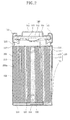
- FIG. 2 is a cross-sectional view of the secondary battery according to the exemplary embodiment of the principles of the present invention.
- a secondary battery according to the exemplary embodiment of the present invention includes an electrode assembly 110, a centre pin 120 disposed in electrode assembly 110, a can 130 housing electrode assembly 110, centre pin 120, and an electrolyte (not shown), a sealing tape 200 disposed between electrode assembly 110 and can 130, and a cap assembly 140 sealing can 130.
- Electrode assembly 110 includes a positive electrode plate 111, a negative electrode plate 112 and a separator 113 disposed between positive electrode plate 111 and negative electrode plate 112.
- Positive electrode plate 111 has a positive electrode collector (not shown) to which a positive electrode active material (not shown) is applied, and a positive electrode tab 114 electrically connected to one side of the positive electrode collector and projecting toward cap assembly 140.
- Negative electrode plate 112 has a negative electrode collector (not shown) to which a negative electrode active material (not shown) is applied, and a negative electrode tab 115 electrically connected to one side of the negative electrode collector and projecting in an opposite direction to positive electrode tab 114.
- positive electrode tab 114 of electrode assembly 110 is described as projecting toward cap assembly 140.
- Negative electrode tab 115 of electrode assembly 110 may, however, project toward cap assembly 140, and positive electrode tab 114 may project in the opposite direction to negative electrode tab 115.
- the positive electrode active material may be a lithium-contained transition metal oxide or a lithium chalcogenide compound such as LiCoO 2 , LiNiO 2 , LiMn 2 O 4 or LiNi 1-x-y Co x M y O 2 (herein, 0 ⁇ x ⁇ 1, 0 ⁇ y ⁇ 1, 0 ⁇ x+y ⁇ 1, and M is a metal such as Al, Sr, Mg or La).
- the negative electrode active material may be a carbon material such as crystalline carbon, amorphous carbon, carbon complex or carbon fiber, lithium metal or a lithium alloy.
- the positive electrode collector or negative electrode collector may be formed of one selected from the group consisting of stainless steel, nickel, copper, aluminum and an alloy thereof.
- the positive electrode collector is formed of aluminum or an aluminum alloy
- the negative electrode collector is formed of copper or a copper alloy to maximize efficiency of electrode assembly 110.
- Separator 113 is interposed between positive electrode plate 111 and negative electrode plate 112 to prevent an electrical short circuit therebetween and allows movement of lithium ions between the two electrode plates.
- Separator 113 may be formed of a polyolefin-based copolymer layer, for example, formed of polyethylene (PE) or polypropylene (PP), or in a multilayer structure thereof.
- Separator 113 may also be formed of a porous layer including a ceramic material, or a combination of the polyolefin-based polymer layer and the porous layer including a ceramic material.
- the ceramic material may be one selected from the group consisting of silica (SiO 2 ), alumina (Al 2 O 3 ), zirconium oxide (ZrO 2 ), titanium oxide (TiO 2 ), and insulating nitrides, hydroxides, alkoxides and ketones thereof.
- the electrolyte solution facilitates movement of lithium ions generated by an electrochemical reaction between positive electrode plate 111 and negative electrode plate 112 of electrode assembly 110 during charge or discharge of the battery.
- the electrolyte solution may be a non-aqueous organic electrolyte solution such as a mixture of a lithium salt and a high purity organic solvent, or a polymer using a polymer electrolyte.
- Centre pin 120 is disposed in electrode assembly 110 to prevent deformation of electrode assembly 110 during the charge or discharge of the battery, and to provide a passage for moving gas generated around electrode assembly 110 due to overcharge, exposure to high heat, or an internal error caused by external impact toward cap assembly 140.
- Centre pin 120 may include a body 122 having a predetermined length, and may further include a sealing member 124 sealing an inner space of body 122 and an extinguishing member 125 inserted into the sealed space of body 122.
- Body 122 may be formed to a predetermined length in a thickness direction of electrode assembly 110.
- Body 122 may have a through hole therein in a lengthwise direction of body 122, which serves as a passage for the gas generated near electrode assembly 110.
- Body 122 may be formed of an insulating material such as polybutylene terephthalate (PBT), or a metallic material such as steel, stainless steel, aluminum or an aluminum alloy to easily move the gas in a high temperature condition such as overcharge or exposure to high heat.
- PBT polybutylene terephthalate
- Sealing member 124 may be melted or broken when the internal error occurs, in order to allow body 122 of centre pin 120 to serve as the passage for the gas generated near electrode assembly 110, and to insert the extinguishing member 125 which is inserted into body 122 into electrode assembly 110.
- Sealing member 124 may be formed of a polymer resin such as polyethylene (PE), polypropylene (PP), or polyethyleneterephthalate (PBT), which is melted or broken down at high temperature. In consideration of a temperature at which the internal error generally occurs in the secondary battery, sealing member 124 may be melted or broken down at 100 to 130°C.
- Can 130 may be formed in a cylindrical shape having a predetermined radius, a top opening and a circular bottom to house electrode assembly 110, centre pin 120 and the electrolyte solution.
- Can 130 may be formed of a metallic material which is lightweight and flexible, such as aluminum, an aluminum alloy or stainless steel. Accordingly, when negative electrode tab 115 projecting in the opposite direction to positive electrode tab 114 is electrically connected to the bottom of can 130, can 130 may serve as a negative electrode terminal.
- Can 130 may include a beading part 135 and a crimping part 137.
- Beading part 135 is formed by inwardly projecting a circumferential surface of can 130 between cap assembly 140 and electrode assembly 110 by a predetermined distance.
- Crimping part 137 is formed by inwardly bending an upper end of can 130 based on cap assembly 140.
- Can 130 formed with beading part 135 and a crimping part 137 prevents separation of cap assembly 140 from can 130, and prevents vertical movement of electrode assembly 110 due to an external force after being sealed using cap assembly 140.
- an upper insulating plate 117 may be disposed on electrode assembly 110 and having one or more holes through which the gas generated around electrode assembly 110 may be moved, and a lower insulating plate 116 may be disposed under electrode assembly 110.
- Cap assembly 140 may include a cap-up 145, a safety vent 142, a current interrupt device (CID) 143, and a gasket 141.
- Cap-up 145 is electrically connected to an external terminal (not shown) and coupled to the top opening of can 130 to seal can 130.
- Safety vent 142 is electrically connected to positive electrode tab 114 of electrode assembly 110 and is deformed or broken when an inner pressure exceeds a predetermined level due to the gas generated around electrode assembly 110 to exhaust the gas.
- Current interrupt device (CID) 143 is formed on safety vent 142 to block an electrical connection between electrode assembly 110 and the external terminal by being damaged or broken as safety vent 142 is deformed or broken due to the inner pressure.
- Gasket 141 insulating cap assembly 140 from can 130.
- cap assembly 140 may further include a ring-shaped positive temperature coefficient (PTC) thermistor 144 disposed between CID 143 and cap-up 145 to prevent overcurrent generated between electrode assembly 110 and an external terminal.
- PTC positive temperature coefficient
- Sealing tape 200 is to prevent unwinding of the electrode assembly wound in a circular shape before being inserted into can 130.
- Sealing tape 200 is disposed to surround a circumferential surface of electrode assembly 110 wound in the circular shape.
- Sealing tape 200 is formed of a heat-shrinkable material which is shrunken at a predetermined temperature, thereby increasing a total thickness of sealing tape 200.
- sealing tape 200 may be formed of polyethylene terephthalate (PET), polytrimethylene terephthalate (PTT), or a mixture thereof.
- PET polyethylene terephthalate
- PTT polytrimethylene terephthalate
- an end of sealing tape 200 is adhered to the outermost end of the wound electrode assembly 110, thereby easily preventing unwinding of electrode assembly 110.
- sealing tape 200 is described as directly surrounding a circumferential surface of electrode assembly 110. There may, however, be disposed at least one of some tape or film (not shown), referred to as a protecting tape, between sealing tape 200 and the electrode assembly 110. In this case, the end of sealing tape 200 is adhered to the outermost end of the wound electrode assembly 110 through at least one protecting tape.
- FIG. 4 is a perspective view of the shape of the electrode assembly including the sealing tape prior to heat shrinkage according to an exemplary embodiment of the present invention.
- sealing tape 200 may include a plurality of trenches or grooves 210 having predetermined lengths along a width direction of sealing tape 200 in a predetermined region.
- the width direction of sealing tape 200 refers to an axial direction when the electrode assembly is wound.
- the heat shrinkage of sealing tape 200 takes place around trenches or grooves 210 at a predetermined temperature, thereby increasing a thickness of a region 200a between trenches or grooves 210 due to the heat shrinkage.
- sealing tape 200 when sealing tape 200 is heated to the predetermined temperature, sealing tape 200 shrinks such that trenches or grooves 210 become polygons or diamonds as shown in FIG. 1 .
- the separator of electrode assembly 110 when sealing tape 200 is shrunken in the width direction, the separator of electrode assembly 110 may also be shrunken. Accordingly, trench or groove 210 may be formed to a predetermined length in the width direction to allow sealing tape 200 to be shrunken in a direction in which electrode assembly 110 is wound.
- Sealing tape 200 may include several sub-sealing tapes 200 as shown in FIG. 3 to prevent the shrinkage of separator 113 at the same time that sealing tape 200 is shrunken.
- a method of fabricating a secondary battery according to an exemplary embodiment of the present invention includes providing an electrode assembly 110 including a positive electrode plate 111, a negative electrode plate 112 and a separator 113 disposed between the two electrode plates, surrounding a circumferential surface of electrode assembly 110 with a sealing tape 200 formed of a heat-shrinkable material, and housing electrode assembly 110 and sealing tape 200 in a can 130.
- sealing tape 200 as shown in FIG. 4 , may include a plurality of trenches or grooves 210 having predetermined lengths to control a region 200a increasing in thickness due to heat shrinkage.
- the method of fabricating is described as surrounding the circumferential surface of electrode assembly 110 with a sealing tape 200.
- the method of fabricating includes surrounding the circumferential surface of electrode assembly 110 with at least one of some tape or film (not shown), and surrounding at least one of some tape or film with the sealing tape 200.
- can 130 is filled with an electrolyte solution.
- a positive electrode tab 114 of electrode assembly 110 is electrically connected to a safety vent 142 of a cap assembly 140. Then, can 130 is sealed using cap assembly 140.
- sealing tape 200 is shrunken by heating the periphery of can 130 at a predetermined temperature, and thus electrode assembly 110 is close to can 130.
- sealing tape 200 since the heat shrinkage of sealing tape 200 progresses around trenches or grooves 210, after the heat shrinkage is completed, sealing tape 200 increases in thickness in region 200a between trenches or grooves 210. As a result, electrode assembly 110 surrounded by sealing tape 200 is close to can 130 in position. Trenches or grooves 210 may be transformed to a polygonal, particularly, a diamond, shape due to the heat shrinkage.
- the predetermined temperature may be about 90 °C or less, and preferably, about 40 °C to 60 °C to prevent denaturation of the electrolyte solution housed in can 130 or damage to the electrode assembly.
- sealing tape 200 When sealing tape 200 is shrunken by less than 50%, electrode assembly 110 may not be sufficiently close to can 130. When sealing tape 200 is shrunken by 70% or more, separator 113 of electrode assembly 110 may also be shrunken.
- sealing tape 200 may be formed of a heat-shrinkable material which is shrunken 50 to 70%, and preferably, a heat-shrinkable material which is shrunken 50 to 70% at about 40 °C to 60 °C to prevent damage to the secondary battery as described above.
- the secondary battery having a centre pin which is disposed in the electrode assembly wound in a cylindrical shape, and the can formed in a cylindrical type have been described.
- a prismatic or pouch-type secondary battery also has an electrical short circuit between an electrode assembly and a cap assembly when the electrode assembly is moved or revolves due to an external impact such as being dropped.
- a sealing tape is formed of a heat-shrinkable material as described herein, and thus the can may be close to the electrode assembly.
- the sealing tape surrounding the circumferential surface of the electrode assembly is formed of a heat-shrinkable material to seal the can by heating the can at a predetermined temperature, resulting in shrinkage of the sealing tape.
- the electrode assembly is close to the can, thereby preventing movement or revolution of the electrode assembly due to the external impact such as being dropped.
- a sealing tape surrounding a circumferential surface of an electrode assembly is formed of a heat-shrinkable material, and a can is sealed using a cap assembly
- the can is heated at a predetermined temperature to thicken a partial region of the sealing tape due to heat shrinkage.
Landscapes
- Engineering & Computer Science (AREA)
- Manufacturing & Machinery (AREA)
- Chemical & Material Sciences (AREA)
- Chemical Kinetics & Catalysis (AREA)
- Electrochemistry (AREA)
- General Chemical & Material Sciences (AREA)
- Secondary Cells (AREA)
- Sealing Battery Cases Or Jackets (AREA)
- Connection Of Batteries Or Terminals (AREA)
Abstract
Description
- The present invention relates to a secondary battery and a method of fabricating the same, and more particularly, to a secondary battery and a method of fabricating the same, in which an electrode assembly is close to a can, thereby preventing a short circuit between the electrode assembly and a cap assembly due to an external impact such as the secondary battery being dropped.
- In recent times, various compact handheld electronic/electrical devices such as cellular phones, notebook computers, camcorders, and so on, have been widely developed and produced. The handheld electronic/electrical devices include a battery pack to be operated without a separate power source. The battery packs may be classified into a nickel-cadmium (Ni-Cd) battery, a nickel-metal hydride (Ni-MH) battery, and a lithium (Li) battery. The battery pack using a secondary (rechargeable) battery is generally used in consideration of economic efficiency.
- It is therefore an aspect of the present invention to provide an improved secondary battery and an improved method of fabricating the same.
- It is another aspect of the present invention to provide a secondary battery and a method of fabricating the same, in which an electrode assembly is inserted into a can to be close thereto. Thus, the electrode assembly can be inserted into the can without damage, and the movement or revolution of the electrode assembly due to an external impact such as being dropped can be prevented.
- According to one aspect of the present invention, a secondary battery may be constructed with an electrode assembly including a positive electrode plate, a negative electrode plate, and a separator interposed therebetween, a sealing tape surrounding a circumferential surface of the electrode assembly, a can housing the electrode assembly, and a cap assembly sealing the can. Here, the sealing tape is formed of a heat-shrinkable material.
- According to another aspect of the present invention, a method of fabricating a secondary battery includes providing an electrode assembly including a positive electrode plate, a negative electrode plate and a separator interposed between the two electrode plates, surrounding a circumferential surface of the electrode assembly with a sealing tape formed of a heat-shrinkable material, housing the electrode assembly, the sealing tape and an electrolyte solution in a can, electrically connecting the electrode assembly to the cap assembly, and sealing the can using the cap assembly, and heating the can at a predetermined temperature to shrink the sealing tape.
- A more complete appreciation of the invention, and many of the attendant advantages thereof, will be readily apparent as the same becomes better understood by reference to the following detailed description when considered in conjunction with the accompanying drawings in which like reference symbols indicate the same or similar components, wherein:
-
FIG. 1 is an exploded oblique view of a secondary battery constructed as an exemplary embodiment according to the principles of the present invention; -
FIG. 2 is a cross-sectional view of a secondary battery constructed as an exemplary embodiment according to the principles of the present invention; -
FIG. 3 is an oblique view of an example of an electrode assembly constructed as an exemplary embodiment according to the principles of the present invention; and -
FIG. 4 is an oblique view of the shape of the electrode assembly prior to heat shrinkage according to an exemplary embodiment of the principles of the present invention. - The above and other objects, features and functions of the present invention will be described more fully with reference to accompanying drawings. Moreover, in the drawings, the length and thickness of an element or a region may be exaggerated for clarity. Also, like numerals denote like elements throughout the specification. Among different types of batteries, such as a nickel-cadmium (Ni-Cd) battery, a nickel-metal hydride (Ni-MH) battery, and a lithium (Li) battery, the lithium secondary battery is widely used for the handheld electronic/electrical devices due to an operating voltage three times higher and a higher energy density per unit weight than the Ni-Cd battery and the Ni-MH battery.
- The lithium secondary battery can be classified into a lithium ion battery using a liquid electrolyte and a lithium polymer battery using a polymer electrolyte according to the kind of the electrolyte to be used. Also the lithium secondary battery can be classified into prismatic, cylindrical and pouch types according to the shape of the battery to be fabricated.
- The secondary battery generally includes an electrode assembly, a can that houses an electrolyte to allow lithium ions to move in the electrode assembly, and a cap assembly that seals the can. Here, the cylindrical secondary battery includes a centre pin having a predetermined length to prevent deformation of the electrode assembly during charge or discharge of the electrode assembly. The centre pin includes a body disposed in the electrode assembly, and a hole that is disposed in the body in a length direction of the centre pin to provide a passage for moving gases generated near the electrode assembly due to overcharge, exposure to high heat, and an internal error toward the cap assembly.
- The electrode assembly includes a positive electrode plate having a positive electrode collector to which a positive electrode active material is applied and a positive electrode tab electrically connected to one side of the positive electrode collector, a negative electrode plate having a negative electrode collector to which a negative electrode active material is applied and a negative electrode tab electrically connected to one side of the negative electrode collector, and a separator disposed between the positive electrode plate and the negative electrode plate.
- The electrolyte allows lithium ions generated by an electrochemical reaction to move between the positive and negative electrode plates of the electrode assembly during charge or discharge of the battery. The electrolyte may be a non-aqueous organic electrolyte solution which is a mixture of a lithium salt and a high-purity organic solvent, or a polymer using a polymer electrolyte.
- To prevent heat generation, combustion and explosion of the secondary battery when an internal error such as damage to the electrode assembly due to overcharge, exposure to high heat, or an external impact occurs, the cap assembly includes a safety vent, which is deformed or broken due to the gas generated around the electrode assembly and moved through the centre pin.
- The secondary battery is designed such that an inner diameter of the can is a bit larger than an outer diameter of the electrode assembly to prevent the damage to the electrode assembly on housing the electrode assembly in the can. Therefore, the electrode assembly may be moved or may revolve due to an external impact such as the secondary battery being dropped, which leads to an electrical short circuit between the electrode assembly and the cap assembly.
-
FIG. 1 is an exploded perspective view of a secondary battery constructed as an exemplary embodiment according to the principles of the present invention, andFIG. 2 is a cross-sectional view of the secondary battery according to the exemplary embodiment of the principles of the present invention. - Referring to
FIGS. 1 and2 , a secondary battery according to the exemplary embodiment of the present invention includes anelectrode assembly 110, acentre pin 120 disposed inelectrode assembly 110, a can 130housing electrode assembly 110,centre pin 120, and an electrolyte (not shown), asealing tape 200 disposed betweenelectrode assembly 110 and can 130, and acap assembly 140 sealing can 130. -
Electrode assembly 110 includes apositive electrode plate 111, anegative electrode plate 112 and aseparator 113 disposed betweenpositive electrode plate 111 andnegative electrode plate 112.Positive electrode plate 111 has a positive electrode collector (not shown) to which a positive electrode active material (not shown) is applied, and apositive electrode tab 114 electrically connected to one side of the positive electrode collector and projecting towardcap assembly 140.Negative electrode plate 112 has a negative electrode collector (not shown) to which a negative electrode active material (not shown) is applied, and anegative electrode tab 115 electrically connected to one side of the negative electrode collector and projecting in an opposite direction topositive electrode tab 114. - Here, in the exemplary embodiment of the present invention,
positive electrode tab 114 ofelectrode assembly 110 is described as projecting towardcap assembly 140.Negative electrode tab 115 ofelectrode assembly 110 may, however, project towardcap assembly 140, andpositive electrode tab 114 may project in the opposite direction tonegative electrode tab 115. - The positive electrode active material may be a lithium-contained transition metal oxide or a lithium chalcogenide compound such as LiCoO2, LiNiO2, LiMn2O4 or LiNi1-x-yCoxMyO2 (herein, 0≤x≤1, 0≤y≤1, 0≤x+y≤1, and M is a metal such as Al, Sr, Mg or La). The negative electrode active material may be a carbon material such as crystalline carbon, amorphous carbon, carbon complex or carbon fiber, lithium metal or a lithium alloy.
- The positive electrode collector or negative electrode collector may be formed of one selected from the group consisting of stainless steel, nickel, copper, aluminum and an alloy thereof. Preferably, the positive electrode collector is formed of aluminum or an aluminum alloy, and the negative electrode collector is formed of copper or a copper alloy to maximize efficiency of
electrode assembly 110. -
Separator 113 is interposed betweenpositive electrode plate 111 andnegative electrode plate 112 to prevent an electrical short circuit therebetween and allows movement of lithium ions between the two electrode plates.Separator 113 may be formed of a polyolefin-based copolymer layer, for example, formed of polyethylene (PE) or polypropylene (PP), or in a multilayer structure thereof.Separator 113 may also be formed of a porous layer including a ceramic material, or a combination of the polyolefin-based polymer layer and the porous layer including a ceramic material. - Here, the ceramic material may be one selected from the group consisting of silica (SiO2), alumina (Al2O3), zirconium oxide (ZrO2), titanium oxide (TiO2), and insulating nitrides, hydroxides, alkoxides and ketones thereof.
- The electrolyte solution facilitates movement of lithium ions generated by an electrochemical reaction between
positive electrode plate 111 andnegative electrode plate 112 ofelectrode assembly 110 during charge or discharge of the battery. The electrolyte solution may be a non-aqueous organic electrolyte solution such as a mixture of a lithium salt and a high purity organic solvent, or a polymer using a polymer electrolyte. -
Centre pin 120 is disposed inelectrode assembly 110 to prevent deformation ofelectrode assembly 110 during the charge or discharge of the battery, and to provide a passage for moving gas generated aroundelectrode assembly 110 due to overcharge, exposure to high heat, or an internal error caused by external impact towardcap assembly 140.Centre pin 120 may include abody 122 having a predetermined length, and may further include a sealingmember 124 sealing an inner space ofbody 122 and an extinguishingmember 125 inserted into the sealed space ofbody 122. -
Body 122 may be formed to a predetermined length in a thickness direction ofelectrode assembly 110.Body 122 may have a through hole therein in a lengthwise direction ofbody 122, which serves as a passage for the gas generated nearelectrode assembly 110.Body 122 may be formed of an insulating material such as polybutylene terephthalate (PBT), or a metallic material such as steel, stainless steel, aluminum or an aluminum alloy to easily move the gas in a high temperature condition such as overcharge or exposure to high heat. - Sealing
member 124 may be melted or broken when the internal error occurs, in order to allowbody 122 ofcentre pin 120 to serve as the passage for the gas generated nearelectrode assembly 110, and to insert the extinguishingmember 125 which is inserted intobody 122 intoelectrode assembly 110.Sealing member 124 may be formed of a polymer resin such as polyethylene (PE), polypropylene (PP), or polyethyleneterephthalate (PBT), which is melted or broken down at high temperature. In consideration of a temperature at which the internal error generally occurs in the secondary battery, sealingmember 124 may be melted or broken down at 100 to 130°C. - Can 130 may be formed in a cylindrical shape having a predetermined radius, a top opening and a circular bottom to
house electrode assembly 110,centre pin 120 and the electrolyte solution. Can 130 may be formed of a metallic material which is lightweight and flexible, such as aluminum, an aluminum alloy or stainless steel. Accordingly, whennegative electrode tab 115 projecting in the opposite direction topositive electrode tab 114 is electrically connected to the bottom ofcan 130, can 130 may serve as a negative electrode terminal. - Can 130 may include a
beading part 135 and a crimpingpart 137. Beadingpart 135 is formed by inwardly projecting a circumferential surface of can 130 betweencap assembly 140 andelectrode assembly 110 by a predetermined distance. Crimpingpart 137 is formed by inwardly bending an upper end of can 130 based oncap assembly 140. Can 130 formed with beadingpart 135 and a crimpingpart 137 prevents separation ofcap assembly 140 fromcan 130, and prevents vertical movement ofelectrode assembly 110 due to an external force after being sealed usingcap assembly 140. - To prevent an unnecessary electrical connection between
electrode assembly 110 andcap assembly 140, and betweenelectrode assembly 110 and can 130, an upperinsulating plate 117 may be disposed onelectrode assembly 110 and having one or more holes through which the gas generated aroundelectrode assembly 110 may be moved, and a lowerinsulating plate 116 may be disposed underelectrode assembly 110. -
Cap assembly 140 may include a cap-up 145, asafety vent 142, a current interrupt device (CID) 143, and agasket 141. Cap-up 145 is electrically connected to an external terminal (not shown) and coupled to the top opening ofcan 130 to seal can 130.Safety vent 142 is electrically connected topositive electrode tab 114 ofelectrode assembly 110 and is deformed or broken when an inner pressure exceeds a predetermined level due to the gas generated aroundelectrode assembly 110 to exhaust the gas. Current interrupt device (CID) 143 is formed onsafety vent 142 to block an electrical connection betweenelectrode assembly 110 and the external terminal by being damaged or broken assafety vent 142 is deformed or broken due to the inner pressure.Gasket 141 insulatingcap assembly 140 fromcan 130. - Here,
cap assembly 140 may further include a ring-shaped positive temperature coefficient (PTC)thermistor 144 disposed betweenCID 143 and cap-up 145 to prevent overcurrent generated betweenelectrode assembly 110 and an external terminal. - Sealing
tape 200 is to prevent unwinding of the electrode assembly wound in a circular shape before being inserted intocan 130. Sealingtape 200 is disposed to surround a circumferential surface ofelectrode assembly 110 wound in the circular shape. Sealingtape 200 is formed of a heat-shrinkable material which is shrunken at a predetermined temperature, thereby increasing a total thickness of sealingtape 200. For example, sealingtape 200 may be formed of polyethylene terephthalate (PET), polytrimethylene terephthalate (PTT), or a mixture thereof. Here, an end of sealingtape 200 is adhered to the outermost end of thewound electrode assembly 110, thereby easily preventing unwinding ofelectrode assembly 110. - In the exemplary embodiment of the present invention, sealing
tape 200 is described as directly surrounding a circumferential surface ofelectrode assembly 110. There may, however, be disposed at least one of some tape or film (not shown), referred to as a protecting tape, between sealingtape 200 and theelectrode assembly 110. In this case, the end of sealingtape 200 is adhered to the outermost end of thewound electrode assembly 110 through at least one protecting tape. -
FIG. 4 is a perspective view of the shape of the electrode assembly including the sealing tape prior to heat shrinkage according to an exemplary embodiment of the present invention. As shown inFIG. 4 , sealingtape 200 may include a plurality of trenches orgrooves 210 having predetermined lengths along a width direction of sealingtape 200 in a predetermined region. The width direction of sealingtape 200 refers to an axial direction when the electrode assembly is wound. The heat shrinkage of sealingtape 200 takes place around trenches orgrooves 210 at a predetermined temperature, thereby increasing a thickness of aregion 200a between trenches orgrooves 210 due to the heat shrinkage. That is, when sealingtape 200 is heated to the predetermined temperature, sealingtape 200 shrinks such that trenches orgrooves 210 become polygons or diamonds as shown inFIG. 1 . Here, when sealingtape 200 is shrunken in the width direction, the separator ofelectrode assembly 110 may also be shrunken. Accordingly, trench or groove 210 may be formed to a predetermined length in the width direction to allow sealingtape 200 to be shrunken in a direction in whichelectrode assembly 110 is wound. - Sealing
tape 200 may include severalsub-sealing tapes 200 as shown inFIG. 3 to prevent the shrinkage ofseparator 113 at the same time that sealingtape 200 is shrunken. - A method of fabricating a secondary battery according to an exemplary embodiment of the present invention includes providing an
electrode assembly 110 including apositive electrode plate 111, anegative electrode plate 112 and aseparator 113 disposed between the two electrode plates, surrounding a circumferential surface ofelectrode assembly 110 with a sealingtape 200 formed of a heat-shrinkable material, andhousing electrode assembly 110 and sealingtape 200 in acan 130. Here, sealingtape 200, as shown inFIG. 4 , may include a plurality of trenches orgrooves 210 having predetermined lengths to control aregion 200a increasing in thickness due to heat shrinkage. - In the exemplary embodiment of the present invention, the method of fabricating is described as surrounding the circumferential surface of
electrode assembly 110 with a sealingtape 200. However, the method of fabricating includes surrounding the circumferential surface ofelectrode assembly 110 with at least one of some tape or film (not shown), and surrounding at least one of some tape or film with the sealingtape 200. - Subsequently, can 130 is filled with an electrolyte solution. A
positive electrode tab 114 ofelectrode assembly 110 is electrically connected to asafety vent 142 of acap assembly 140. Then, can 130 is sealed usingcap assembly 140. - Afterwards, sealing
tape 200 is shrunken by heating the periphery ofcan 130 at a predetermined temperature, and thuselectrode assembly 110 is close tocan 130. Here, since the heat shrinkage of sealingtape 200 progresses around trenches orgrooves 210, after the heat shrinkage is completed, sealingtape 200 increases in thickness inregion 200a between trenches orgrooves 210. As a result,electrode assembly 110 surrounded by sealingtape 200 is close to can 130 in position. Trenches orgrooves 210 may be transformed to a polygonal, particularly, a diamond, shape due to the heat shrinkage. - The predetermined temperature may be about 90 °C or less, and preferably, about 40 °C to 60 °C to prevent denaturation of the electrolyte solution housed in
can 130 or damage to the electrode assembly. - When sealing
tape 200 is shrunken by less than 50%,electrode assembly 110 may not be sufficiently close tocan 130. When sealingtape 200 is shrunken by 70% or more,separator 113 ofelectrode assembly 110 may also be shrunken. Thus, sealingtape 200 may be formed of a heat-shrinkable material which is shrunken 50 to 70%, and preferably, a heat-shrinkable material which is shrunken 50 to 70% at about 40 °C to 60 °C to prevent damage to the secondary battery as described above. - In the exemplary embodiment of the present invention, the secondary battery having a centre pin, which is disposed in the electrode assembly wound in a cylindrical shape, and the can formed in a cylindrical type have been described. However, a prismatic or pouch-type secondary battery also has an electrical short circuit between an electrode assembly and a cap assembly when the electrode assembly is moved or revolves due to an external impact such as being dropped. Thus, a sealing tape is formed of a heat-shrinkable material as described herein, and thus the can may be close to the electrode assembly.
- Consequently, in the secondary battery according to the exemplary embodiment of the present invention, the sealing tape surrounding the circumferential surface of the electrode assembly is formed of a heat-shrinkable material to seal the can by heating the can at a predetermined temperature, resulting in shrinkage of the sealing tape. Thus, the electrode assembly is close to the can, thereby preventing movement or revolution of the electrode assembly due to the external impact such as being dropped.
- According to the present invention, in a secondary battery, after a sealing tape surrounding a circumferential surface of an electrode assembly is formed of a heat-shrinkable material, and a can is sealed using a cap assembly, the can is heated at a predetermined temperature to thicken a partial region of the sealing tape due to heat shrinkage. Thus, an electrical short circuit between the electrode assembly and the cap assembly due to an external impact such as being dropped can be prevented.
- Although the present invention has been described with reference to certain exemplary embodiments thereof, it will be understood by those skilled in the art that a variety of modifications and variations may be made to the present invention without departing from the scope of the present invention defined in the appended claims.
Claims (15)
- A secondary battery, comprising:an electrode assembly including a positive electrode plate, a negative electrode plate, and a separator interposed therebetween;a sealing tape surrounding a circumferential surface of the electrode assembly;a can housing the electrode assembly; anda cap assembly sealing the can,the sealing tape being formed of a heat-shrinkable material.
- The secondary battery according to claim 1, wherein the sealing tape is a material which shrinks by about 50 to 70% at about 40 °C to 60 °C.
- The secondary battery according to claim 1 or 2, wherein the sealing tape comprises a plurality of polygonal holes formed in a region that increases in thickness due to heat shrinkage.
- The secondary battery according to claim 3, wherein the polygonal holes are formed in diamond shapes.
- The secondary battery according to any one of the preceding claims, wherein before the heat shrinkage, the sealing tape comprises a plurality of trenches formed in a predetermined length along a width direction of the sealing tape, and said plurality of trenches transform into polygonal holes after the heat shrinkage.
- The secondary battery according to any one of the preceding claims, wherein one end of the sealing tape is adhered to a circumferential surface in which the outermost end of the electrode assembly is disposed.
- The secondary battery according to any one of the preceding claims, wherein the electrode assembly comprises a centre pin disposed therein.
- The secondary battery according to any one of the preceding claims, wherein the sealing tape comprises a plurality of sub-sealing tapes surrounding the circumferential surface of the electrode assembly.
- The secondary battery according to any one of the preceding claims, wherein a thickness of at least one region of the sealing tape increases due to heat shrinkage of the sealing tape.
- The secondary battery according to any one of the preceding claims, further comprising:at least one protecting tape disposed between the sealing tape and the electrode assembly.
- A method of fabricating a secondary battery according to any one of the preceding claims, comprising:providing an electrode assembly including a positive electrode plate, a negative electrode plate and a separator interposed between the two electrode plates;surrounding a circumferential surface of the electrode assembly with a sealing tape formed of a heat-shrinkable material;housing the electrode assembly, the sealing tape and an electrolyte solution in a can;electrically connecting the electrode assembly to the cap assembly, and sealing the can using the cap assembly; andheating the can at a predetermined temperature to shrink the sealing tape.
- The method according to claim 11, wherein the predetermined temperature is in the range of 40 °C to 60 °C.
- The method according to claim 11 or 12, wherein one end of the sealing tape is adhered to the outermost end of the electrode assembly, and the electrode assembly is surrounded by the sealing tape.
- The method according to claim 11, 12 or 13, wherein a plurality of trenches or grooves are formed in a predetermined region of the sealing tape before the can is heated to allow heat shrinkage of the sealing tape to progress around the trenches or grooves.
- The method according to any one of claims 11 to 14, further comprising:surrounding a circumferential surface of the electrode assembly with at least one protecting tape;surrounding a surface of the at least one protecting tape with the sealing tape.
Applications Claiming Priority (1)
| Application Number | Priority Date | Filing Date | Title |
|---|---|---|---|
| KR1020090093223A KR101118261B1 (en) | 2009-09-30 | 2009-09-30 | Secondary Battery and Fabrication method of the same |
Publications (2)
| Publication Number | Publication Date |
|---|---|
| EP2312682A1 true EP2312682A1 (en) | 2011-04-20 |
| EP2312682B1 EP2312682B1 (en) | 2014-01-08 |
Family
ID=43303671
Family Applications (1)
| Application Number | Title | Priority Date | Filing Date |
|---|---|---|---|
| EP10175380.4A Active EP2312682B1 (en) | 2009-09-30 | 2010-09-06 | Secondary battery and method of fabricating the same |
Country Status (5)
| Country | Link |
|---|---|
| US (1) | US8455124B2 (en) |
| EP (1) | EP2312682B1 (en) |
| JP (1) | JP5307746B2 (en) |
| KR (1) | KR101118261B1 (en) |
| CN (1) | CN102035016B (en) |
Cited By (1)
| Publication number | Priority date | Publication date | Assignee | Title |
|---|---|---|---|---|
| EP4567956A1 (en) * | 2023-12-08 | 2025-06-11 | Prime Planet Energy & Solutions, Inc. | Method for manufacturing a secondary battery and secondary battery |
Families Citing this family (19)
| Publication number | Priority date | Publication date | Assignee | Title |
|---|---|---|---|---|
| KR100973312B1 (en) | 2008-03-25 | 2010-07-30 | 삼성에스디아이 주식회사 | Center pin for secondary battery and secondary battery having same |
| JP5962653B2 (en) * | 2011-05-10 | 2016-08-03 | 日立化成株式会社 | Winding type secondary battery |
| KR101885907B1 (en) * | 2011-09-26 | 2018-09-10 | 삼성에스디아이 주식회사 | Rechargeable battery |
| US9401504B2 (en) | 2012-06-08 | 2016-07-26 | Samsung Sdi Co., Ltd. | Battery cell |
| KR101904894B1 (en) * | 2012-08-07 | 2018-10-05 | 삼성에스디아이 주식회사 | Rechargeable battery |
| KR101968345B1 (en) | 2012-08-28 | 2019-04-11 | 삼성에스디아이 주식회사 | A secondary battery |
| US9634351B2 (en) * | 2014-03-14 | 2017-04-25 | Apple Inc. | Mechanical structures for maintaining structural integrity in cylindrical pouch cell batteries |
| WO2016032438A1 (en) * | 2014-08-26 | 2016-03-03 | Halliburton Energy Services, Inc. | Systems and methods for analyzing the characteristics and compositions of cement additives |
| KR102238623B1 (en) * | 2014-10-15 | 2021-04-08 | 에스케이이노베이션 주식회사 | Jelly roll for use in a secondary battery |
| JP6394894B2 (en) * | 2014-12-19 | 2018-09-26 | 株式会社豊田自動織機 | Power storage device |
| KR102635445B1 (en) * | 2016-01-06 | 2024-02-13 | 삼성에스디아이 주식회사 | Secondary battery |
| US11949060B2 (en) | 2018-09-11 | 2024-04-02 | Energizer Brands, Llc | Rechargeable hearing aid battery with slotted grommet |
| KR102866763B1 (en) | 2019-08-19 | 2025-09-29 | 삼성에스디아이 주식회사 | Rechargeable battery |
| US12119474B1 (en) | 2020-04-02 | 2024-10-15 | Energizer Brands, Llc | Electrode bonding system and method of use |
| US11641044B1 (en) | 2020-04-14 | 2023-05-02 | Energizer Brands, Llc | Battery housing and systems and methods of making thereof |
| KR102798474B1 (en) * | 2020-12-01 | 2025-04-22 | 주식회사 엘지에너지솔루션 | Charging and discharging device of battery cell, and charging and discharging method of battery cell using the same |
| US12087899B1 (en) | 2021-05-19 | 2024-09-10 | Energizer Brands, Llc | Electrode and separator feed system and method of use |
| EP4503238A4 (en) * | 2022-11-04 | 2025-12-17 | Contemporary Amperex Technology Hong Kong Ltd | ELECTRODE ASSEMBLY, FORMING PROCESS, BATTERY ELEMENT, BATTERY AND ELECTRICAL DEVICE |
| KR20240095067A (en) * | 2022-12-16 | 2024-06-25 | 주식회사 엘지에너지솔루션 | Cylindrical lithium-sulfur battery and preparation method thereof |
Citations (6)
| Publication number | Priority date | Publication date | Assignee | Title |
|---|---|---|---|---|
| JPS62278771A (en) * | 1986-05-27 | 1987-12-03 | Shin Kobe Electric Mach Co Ltd | Sealed lead-acid battery |
| JPH04184871A (en) * | 1990-11-19 | 1992-07-01 | Sony Corp | Battery |
| US6040085A (en) * | 1994-03-31 | 2000-03-21 | Valence Technology, Inc. | Battery packaging |
| US20060154138A1 (en) * | 2005-01-12 | 2006-07-13 | Sanyo Electric Co., Ltd. | Nonaqueous electrolyte battery |
| US20080233474A1 (en) * | 2007-03-19 | 2008-09-25 | Sukjung Son | Rechargeable battery and its fabrication method |
| EP2254187A1 (en) * | 2009-05-18 | 2010-11-24 | Samsung SDI Co., Ltd. | Secondary battery and manufacturing method of the same |
Family Cites Families (17)
| Publication number | Priority date | Publication date | Assignee | Title |
|---|---|---|---|---|
| JPH09302109A (en) * | 1996-05-14 | 1997-11-25 | Denki Kagaku Kogyo Kk | Heat shrinkable tube for batteries |
| KR100522681B1 (en) * | 1999-10-25 | 2005-10-19 | 삼성에스디아이 주식회사 | Sealed battery |
| JP2003243036A (en) * | 2002-02-18 | 2003-08-29 | Shin Kobe Electric Mach Co Ltd | Cylindrical lithium secondary battery |
| JP4558279B2 (en) * | 2003-02-21 | 2010-10-06 | パナソニック株式会社 | Square battery and method for manufacturing the same |
| JP2004273153A (en) * | 2003-03-05 | 2004-09-30 | Sony Corp | battery |
| JP4495994B2 (en) * | 2004-03-29 | 2010-07-07 | 株式会社東芝 | Nonaqueous electrolyte secondary battery |
| KR100599691B1 (en) | 2004-07-28 | 2006-07-13 | 삼성에스디아이 주식회사 | Secondary battery and electrode group used for it |
| JP4499680B2 (en) | 2005-03-30 | 2010-07-07 | 三星エスディアイ株式会社 | Cylindrical lithium ion secondary battery |
| KR100719725B1 (en) * | 2005-12-29 | 2007-05-17 | 삼성에스디아이 주식회사 | Electrode assembly for lithium secondary battery and lithium secondary battery using same |
| JP4795177B2 (en) * | 2005-12-29 | 2011-10-19 | 三星エスディアイ株式会社 | Lithium ion secondary battery |
| KR20080035226A (en) | 2006-10-18 | 2008-04-23 | 삼성에스디아이 주식회사 | Cylindrical secondary battery |
| KR100859637B1 (en) * | 2007-06-01 | 2008-09-23 | 삼성에스디아이 주식회사 | Lithium secondary battery |
| KR100917734B1 (en) | 2007-07-19 | 2009-09-21 | 삼성에스디아이 주식회사 | Pouch Type Lithium Secondary Battery |
| JP2009199974A (en) * | 2008-02-25 | 2009-09-03 | Panasonic Corp | Electrode group for nonaqueous secondary battery, and secondary battery using the same |
| US8347622B2 (en) * | 2008-03-28 | 2013-01-08 | Hitachi, Ltd. | Master cylinder |
| JP4952658B2 (en) * | 2008-06-02 | 2012-06-13 | ソニー株式会社 | Battery element exterior member and non-aqueous electrolyte secondary battery using the same |
| EP2273599B1 (en) | 2009-07-08 | 2016-04-13 | Samsung SDI Co., Ltd. | Secondary battery and method of manufacturing |
-
2009
- 2009-09-30 KR KR1020090093223A patent/KR101118261B1/en active Active
-
2010
- 2010-02-18 JP JP2010033588A patent/JP5307746B2/en active Active
- 2010-08-27 US US12/870,352 patent/US8455124B2/en active Active
- 2010-09-06 EP EP10175380.4A patent/EP2312682B1/en active Active
- 2010-09-29 CN CN201010299097.2A patent/CN102035016B/en active Active
Patent Citations (6)
| Publication number | Priority date | Publication date | Assignee | Title |
|---|---|---|---|---|
| JPS62278771A (en) * | 1986-05-27 | 1987-12-03 | Shin Kobe Electric Mach Co Ltd | Sealed lead-acid battery |
| JPH04184871A (en) * | 1990-11-19 | 1992-07-01 | Sony Corp | Battery |
| US6040085A (en) * | 1994-03-31 | 2000-03-21 | Valence Technology, Inc. | Battery packaging |
| US20060154138A1 (en) * | 2005-01-12 | 2006-07-13 | Sanyo Electric Co., Ltd. | Nonaqueous electrolyte battery |
| US20080233474A1 (en) * | 2007-03-19 | 2008-09-25 | Sukjung Son | Rechargeable battery and its fabrication method |
| EP2254187A1 (en) * | 2009-05-18 | 2010-11-24 | Samsung SDI Co., Ltd. | Secondary battery and manufacturing method of the same |
Cited By (1)
| Publication number | Priority date | Publication date | Assignee | Title |
|---|---|---|---|---|
| EP4567956A1 (en) * | 2023-12-08 | 2025-06-11 | Prime Planet Energy & Solutions, Inc. | Method for manufacturing a secondary battery and secondary battery |
Also Published As
| Publication number | Publication date |
|---|---|
| US8455124B2 (en) | 2013-06-04 |
| KR101118261B1 (en) | 2012-03-20 |
| EP2312682B1 (en) | 2014-01-08 |
| JP2011077020A (en) | 2011-04-14 |
| CN102035016B (en) | 2014-06-25 |
| JP5307746B2 (en) | 2013-10-02 |
| CN102035016A (en) | 2011-04-27 |
| US20110076549A1 (en) | 2011-03-31 |
| KR20110035484A (en) | 2011-04-06 |
Similar Documents
| Publication | Publication Date | Title |
|---|---|---|
| EP2312682B1 (en) | Secondary battery and method of fabricating the same | |
| KR100894626B1 (en) | Cap assembly and secondary battery having same | |
| CN100461524C (en) | Colloidal winding type electrode assembly and lithium secondary battery having the electrode assembly | |
| US20090011329A1 (en) | Secondary battery | |
| KR100989840B1 (en) | Cap assembly and secondary battery having same | |
| KR100891382B1 (en) | Center pin of cylindrical secondary battery and cylindrical secondary battery having same | |
| US9219263B2 (en) | Center pin for secondary battery and secondary battery having the same | |
| KR100601555B1 (en) | Wound electrode assembly and lithium secondary battery using same | |
| KR100670451B1 (en) | Electrode assembly and lithium ion secondary battery having same | |
| JP5379048B2 (en) | Secondary battery | |
| KR101180917B1 (en) | Secondary Battery | |
| JP2004139809A (en) | Sealed battery | |
| US20260094955A1 (en) | Secondary battery and battery module | |
| US20100310920A1 (en) | Center pin for secondary battery and secondary battery including the same | |
| KR100659876B1 (en) | Secondary battery | |
| KR100670431B1 (en) | Lithium secondary battery |
Legal Events
| Date | Code | Title | Description |
|---|---|---|---|
| PUAI | Public reference made under article 153(3) epc to a published international application that has entered the european phase |
Free format text: ORIGINAL CODE: 0009012 |
|
| 17P | Request for examination filed |
Effective date: 20100906 |
|
| AK | Designated contracting states |
Kind code of ref document: A1 Designated state(s): AL AT BE BG CH CY CZ DE DK EE ES FI FR GB GR HR HU IE IS IT LI LT LU LV MC MK MT NL NO PL PT RO SE SI SK SM TR |
|
| AX | Request for extension of the european patent |
Extension state: BA ME RS |
|
| 17Q | First examination report despatched |
Effective date: 20120315 |
|
| GRAP | Despatch of communication of intention to grant a patent |
Free format text: ORIGINAL CODE: EPIDOSNIGR1 |
|
| INTG | Intention to grant announced |
Effective date: 20130718 |
|
| GRAS | Grant fee paid |
Free format text: ORIGINAL CODE: EPIDOSNIGR3 |
|
| GRAA | (expected) grant |
Free format text: ORIGINAL CODE: 0009210 |
|
| AK | Designated contracting states |
Kind code of ref document: B1 Designated state(s): AL AT BE BG CH CY CZ DE DK EE ES FI FR GB GR HR HU IE IS IT LI LT LU LV MC MK MT NL NO PL PT RO SE SI SK SM TR |
|
| REG | Reference to a national code |
Ref country code: GB Ref legal event code: FG4D |
|
| REG | Reference to a national code |
Ref country code: CH Ref legal event code: EP |
|
| REG | Reference to a national code |
Ref country code: IE Ref legal event code: FG4D |
|
| REG | Reference to a national code |
Ref country code: AT Ref legal event code: REF Ref document number: 649219 Country of ref document: AT Kind code of ref document: T Effective date: 20140215 |
|
| REG | Reference to a national code |
Ref country code: DE Ref legal event code: R096 Ref document number: 602010012919 Country of ref document: DE Effective date: 20140220 |
|
| REG | Reference to a national code |
Ref country code: AT Ref legal event code: MK05 Ref document number: 649219 Country of ref document: AT Kind code of ref document: T Effective date: 20140108 |
|
| REG | Reference to a national code |
Ref country code: NL Ref legal event code: VDEP Effective date: 20140108 |
|
| REG | Reference to a national code |
Ref country code: LT Ref legal event code: MG4D |
|
| PG25 | Lapsed in a contracting state [announced via postgrant information from national office to epo] |
Ref country code: LT Free format text: LAPSE BECAUSE OF FAILURE TO SUBMIT A TRANSLATION OF THE DESCRIPTION OR TO PAY THE FEE WITHIN THE PRESCRIBED TIME-LIMIT Effective date: 20140108 Ref country code: IS Free format text: LAPSE BECAUSE OF FAILURE TO SUBMIT A TRANSLATION OF THE DESCRIPTION OR TO PAY THE FEE WITHIN THE PRESCRIBED TIME-LIMIT Effective date: 20140508 Ref country code: NO Free format text: LAPSE BECAUSE OF FAILURE TO SUBMIT A TRANSLATION OF THE DESCRIPTION OR TO PAY THE FEE WITHIN THE PRESCRIBED TIME-LIMIT Effective date: 20140408 |
|
| PG25 | Lapsed in a contracting state [announced via postgrant information from national office to epo] |
Ref country code: ES Free format text: LAPSE BECAUSE OF FAILURE TO SUBMIT A TRANSLATION OF THE DESCRIPTION OR TO PAY THE FEE WITHIN THE PRESCRIBED TIME-LIMIT Effective date: 20140108 Ref country code: SE Free format text: LAPSE BECAUSE OF FAILURE TO SUBMIT A TRANSLATION OF THE DESCRIPTION OR TO PAY THE FEE WITHIN THE PRESCRIBED TIME-LIMIT Effective date: 20140108 Ref country code: PT Free format text: LAPSE BECAUSE OF FAILURE TO SUBMIT A TRANSLATION OF THE DESCRIPTION OR TO PAY THE FEE WITHIN THE PRESCRIBED TIME-LIMIT Effective date: 20140508 Ref country code: FI Free format text: LAPSE BECAUSE OF FAILURE TO SUBMIT A TRANSLATION OF THE DESCRIPTION OR TO PAY THE FEE WITHIN THE PRESCRIBED TIME-LIMIT Effective date: 20140108 Ref country code: AT Free format text: LAPSE BECAUSE OF FAILURE TO SUBMIT A TRANSLATION OF THE DESCRIPTION OR TO PAY THE FEE WITHIN THE PRESCRIBED TIME-LIMIT Effective date: 20140108 Ref country code: CY Free format text: LAPSE BECAUSE OF FAILURE TO SUBMIT A TRANSLATION OF THE DESCRIPTION OR TO PAY THE FEE WITHIN THE PRESCRIBED TIME-LIMIT Effective date: 20140108 Ref country code: NL Free format text: LAPSE BECAUSE OF FAILURE TO SUBMIT A TRANSLATION OF THE DESCRIPTION OR TO PAY THE FEE WITHIN THE PRESCRIBED TIME-LIMIT Effective date: 20140108 |
|
| PG25 | Lapsed in a contracting state [announced via postgrant information from national office to epo] |
Ref country code: HR Free format text: LAPSE BECAUSE OF FAILURE TO SUBMIT A TRANSLATION OF THE DESCRIPTION OR TO PAY THE FEE WITHIN THE PRESCRIBED TIME-LIMIT Effective date: 20140108 Ref country code: BE Free format text: LAPSE BECAUSE OF FAILURE TO SUBMIT A TRANSLATION OF THE DESCRIPTION OR TO PAY THE FEE WITHIN THE PRESCRIBED TIME-LIMIT Effective date: 20140108 Ref country code: LV Free format text: LAPSE BECAUSE OF FAILURE TO SUBMIT A TRANSLATION OF THE DESCRIPTION OR TO PAY THE FEE WITHIN THE PRESCRIBED TIME-LIMIT Effective date: 20140108 |
|
| REG | Reference to a national code |
Ref country code: DE Ref legal event code: R097 Ref document number: 602010012919 Country of ref document: DE |
|
| PG25 | Lapsed in a contracting state [announced via postgrant information from national office to epo] |
Ref country code: EE Free format text: LAPSE BECAUSE OF FAILURE TO SUBMIT A TRANSLATION OF THE DESCRIPTION OR TO PAY THE FEE WITHIN THE PRESCRIBED TIME-LIMIT Effective date: 20140108 Ref country code: RO Free format text: LAPSE BECAUSE OF FAILURE TO SUBMIT A TRANSLATION OF THE DESCRIPTION OR TO PAY THE FEE WITHIN THE PRESCRIBED TIME-LIMIT Effective date: 20140108 Ref country code: DK Free format text: LAPSE BECAUSE OF FAILURE TO SUBMIT A TRANSLATION OF THE DESCRIPTION OR TO PAY THE FEE WITHIN THE PRESCRIBED TIME-LIMIT Effective date: 20140108 Ref country code: CZ Free format text: LAPSE BECAUSE OF FAILURE TO SUBMIT A TRANSLATION OF THE DESCRIPTION OR TO PAY THE FEE WITHIN THE PRESCRIBED TIME-LIMIT Effective date: 20140108 |
|
| PLBE | No opposition filed within time limit |
Free format text: ORIGINAL CODE: 0009261 |
|
| STAA | Information on the status of an ep patent application or granted ep patent |
Free format text: STATUS: NO OPPOSITION FILED WITHIN TIME LIMIT |
|
| PG25 | Lapsed in a contracting state [announced via postgrant information from national office to epo] |
Ref country code: SK Free format text: LAPSE BECAUSE OF FAILURE TO SUBMIT A TRANSLATION OF THE DESCRIPTION OR TO PAY THE FEE WITHIN THE PRESCRIBED TIME-LIMIT Effective date: 20140108 Ref country code: PL Free format text: LAPSE BECAUSE OF FAILURE TO SUBMIT A TRANSLATION OF THE DESCRIPTION OR TO PAY THE FEE WITHIN THE PRESCRIBED TIME-LIMIT Effective date: 20140108 |
|
| 26N | No opposition filed |
Effective date: 20141009 |
|
| REG | Reference to a national code |
Ref country code: DE Ref legal event code: R097 Ref document number: 602010012919 Country of ref document: DE Effective date: 20141009 |
|
| PG25 | Lapsed in a contracting state [announced via postgrant information from national office to epo] |
Ref country code: LU Free format text: LAPSE BECAUSE OF FAILURE TO SUBMIT A TRANSLATION OF THE DESCRIPTION OR TO PAY THE FEE WITHIN THE PRESCRIBED TIME-LIMIT Effective date: 20140906 Ref country code: MC Free format text: LAPSE BECAUSE OF FAILURE TO SUBMIT A TRANSLATION OF THE DESCRIPTION OR TO PAY THE FEE WITHIN THE PRESCRIBED TIME-LIMIT Effective date: 20140108 |
|
| REG | Reference to a national code |
Ref country code: CH Ref legal event code: PL |
|
| PG25 | Lapsed in a contracting state [announced via postgrant information from national office to epo] |
Ref country code: SI Free format text: LAPSE BECAUSE OF FAILURE TO SUBMIT A TRANSLATION OF THE DESCRIPTION OR TO PAY THE FEE WITHIN THE PRESCRIBED TIME-LIMIT Effective date: 20140108 |
|
| REG | Reference to a national code |
Ref country code: IE Ref legal event code: MM4A |
|
| PG25 | Lapsed in a contracting state [announced via postgrant information from national office to epo] |
Ref country code: CH Free format text: LAPSE BECAUSE OF NON-PAYMENT OF DUE FEES Effective date: 20140930 Ref country code: LI Free format text: LAPSE BECAUSE OF NON-PAYMENT OF DUE FEES Effective date: 20140930 |
|
| PG25 | Lapsed in a contracting state [announced via postgrant information from national office to epo] |
Ref country code: IE Free format text: LAPSE BECAUSE OF NON-PAYMENT OF DUE FEES Effective date: 20140906 |
|
| PG25 | Lapsed in a contracting state [announced via postgrant information from national office to epo] |
Ref country code: SM Free format text: LAPSE BECAUSE OF FAILURE TO SUBMIT A TRANSLATION OF THE DESCRIPTION OR TO PAY THE FEE WITHIN THE PRESCRIBED TIME-LIMIT Effective date: 20140108 |
|
| PG25 | Lapsed in a contracting state [announced via postgrant information from national office to epo] |
Ref country code: GR Free format text: LAPSE BECAUSE OF FAILURE TO SUBMIT A TRANSLATION OF THE DESCRIPTION OR TO PAY THE FEE WITHIN THE PRESCRIBED TIME-LIMIT Effective date: 20140409 Ref country code: BG Free format text: LAPSE BECAUSE OF FAILURE TO SUBMIT A TRANSLATION OF THE DESCRIPTION OR TO PAY THE FEE WITHIN THE PRESCRIBED TIME-LIMIT Effective date: 20140108 Ref country code: MT Free format text: LAPSE BECAUSE OF FAILURE TO SUBMIT A TRANSLATION OF THE DESCRIPTION OR TO PAY THE FEE WITHIN THE PRESCRIBED TIME-LIMIT Effective date: 20140108 Ref country code: IT Free format text: LAPSE BECAUSE OF FAILURE TO SUBMIT A TRANSLATION OF THE DESCRIPTION OR TO PAY THE FEE WITHIN THE PRESCRIBED TIME-LIMIT Effective date: 20140108 |
|
| PG25 | Lapsed in a contracting state [announced via postgrant information from national office to epo] |
Ref country code: HU Free format text: LAPSE BECAUSE OF FAILURE TO SUBMIT A TRANSLATION OF THE DESCRIPTION OR TO PAY THE FEE WITHIN THE PRESCRIBED TIME-LIMIT; INVALID AB INITIO Effective date: 20100906 Ref country code: TR Free format text: LAPSE BECAUSE OF FAILURE TO SUBMIT A TRANSLATION OF THE DESCRIPTION OR TO PAY THE FEE WITHIN THE PRESCRIBED TIME-LIMIT Effective date: 20140108 |
|
| REG | Reference to a national code |
Ref country code: FR Ref legal event code: PLFP Year of fee payment: 7 |
|
| REG | Reference to a national code |
Ref country code: FR Ref legal event code: PLFP Year of fee payment: 8 |
|
| PG25 | Lapsed in a contracting state [announced via postgrant information from national office to epo] |
Ref country code: MK Free format text: LAPSE BECAUSE OF FAILURE TO SUBMIT A TRANSLATION OF THE DESCRIPTION OR TO PAY THE FEE WITHIN THE PRESCRIBED TIME-LIMIT Effective date: 20140108 |
|
| REG | Reference to a national code |
Ref country code: FR Ref legal event code: PLFP Year of fee payment: 9 |
|
| PG25 | Lapsed in a contracting state [announced via postgrant information from national office to epo] |
Ref country code: AL Free format text: LAPSE BECAUSE OF FAILURE TO SUBMIT A TRANSLATION OF THE DESCRIPTION OR TO PAY THE FEE WITHIN THE PRESCRIBED TIME-LIMIT Effective date: 20140108 |
|
| P01 | Opt-out of the competence of the unified patent court (upc) registered |
Effective date: 20230528 |
|
| PGFP | Annual fee paid to national office [announced via postgrant information from national office to epo] |
Ref country code: DE Payment date: 20250902 Year of fee payment: 16 |
|
| PGFP | Annual fee paid to national office [announced via postgrant information from national office to epo] |
Ref country code: GB Payment date: 20250904 Year of fee payment: 16 |
|
| PGFP | Annual fee paid to national office [announced via postgrant information from national office to epo] |
Ref country code: FR Payment date: 20250908 Year of fee payment: 16 |