EP2312655A1 - Semiconductor light-emitting device and method for fabricating the same - Google Patents
Semiconductor light-emitting device and method for fabricating the same Download PDFInfo
- Publication number
- EP2312655A1 EP2312655A1 EP10166248A EP10166248A EP2312655A1 EP 2312655 A1 EP2312655 A1 EP 2312655A1 EP 10166248 A EP10166248 A EP 10166248A EP 10166248 A EP10166248 A EP 10166248A EP 2312655 A1 EP2312655 A1 EP 2312655A1
- Authority
- EP
- European Patent Office
- Prior art keywords
- layer
- emitting device
- light
- semiconductor light
- channel
- Prior art date
- Legal status (The legal status is an assumption and is not a legal conclusion. Google has not performed a legal analysis and makes no representation as to the accuracy of the status listed.)
- Granted
Links
Images


Classifications
-
- H—ELECTRICITY
- H01—ELECTRIC ELEMENTS
- H01L—SEMICONDUCTOR DEVICES NOT COVERED BY CLASS H10
- H01L33/00—Semiconductor devices with at least one potential-jump barrier or surface barrier specially adapted for light emission; Processes or apparatus specially adapted for the manufacture or treatment thereof or of parts thereof; Details thereof
- H01L33/44—Semiconductor devices with at least one potential-jump barrier or surface barrier specially adapted for light emission; Processes or apparatus specially adapted for the manufacture or treatment thereof or of parts thereof; Details thereof characterised by the coatings, e.g. passivation layer or anti-reflective coating
-
- H—ELECTRICITY
- H01—ELECTRIC ELEMENTS
- H01L—SEMICONDUCTOR DEVICES NOT COVERED BY CLASS H10
- H01L33/00—Semiconductor devices with at least one potential-jump barrier or surface barrier specially adapted for light emission; Processes or apparatus specially adapted for the manufacture or treatment thereof or of parts thereof; Details thereof
- H01L33/36—Semiconductor devices with at least one potential-jump barrier or surface barrier specially adapted for light emission; Processes or apparatus specially adapted for the manufacture or treatment thereof or of parts thereof; Details thereof characterised by the electrodes
- H01L33/40—Materials therefor
- H01L33/405—Reflective materials
-
- H—ELECTRICITY
- H01—ELECTRIC ELEMENTS
- H01L—SEMICONDUCTOR DEVICES NOT COVERED BY CLASS H10
- H01L2224/00—Indexing scheme for arrangements for connecting or disconnecting semiconductor or solid-state bodies and methods related thereto as covered by H01L24/00
- H01L2224/01—Means for bonding being attached to, or being formed on, the surface to be connected, e.g. chip-to-package, die-attach, "first-level" interconnects; Manufacturing methods related thereto
- H01L2224/42—Wire connectors; Manufacturing methods related thereto
- H01L2224/47—Structure, shape, material or disposition of the wire connectors after the connecting process
- H01L2224/48—Structure, shape, material or disposition of the wire connectors after the connecting process of an individual wire connector
- H01L2224/4805—Shape
- H01L2224/4809—Loop shape
- H01L2224/48091—Arched
-
- H—ELECTRICITY
- H01—ELECTRIC ELEMENTS
- H01L—SEMICONDUCTOR DEVICES NOT COVERED BY CLASS H10
- H01L2224/00—Indexing scheme for arrangements for connecting or disconnecting semiconductor or solid-state bodies and methods related thereto as covered by H01L24/00
- H01L2224/01—Means for bonding being attached to, or being formed on, the surface to be connected, e.g. chip-to-package, die-attach, "first-level" interconnects; Manufacturing methods related thereto
- H01L2224/42—Wire connectors; Manufacturing methods related thereto
- H01L2224/47—Structure, shape, material or disposition of the wire connectors after the connecting process
- H01L2224/48—Structure, shape, material or disposition of the wire connectors after the connecting process of an individual wire connector
- H01L2224/481—Disposition
- H01L2224/48151—Connecting between a semiconductor or solid-state body and an item not being a semiconductor or solid-state body, e.g. chip-to-substrate, chip-to-passive
- H01L2224/48221—Connecting between a semiconductor or solid-state body and an item not being a semiconductor or solid-state body, e.g. chip-to-substrate, chip-to-passive the body and the item being stacked
- H01L2224/48245—Connecting between a semiconductor or solid-state body and an item not being a semiconductor or solid-state body, e.g. chip-to-substrate, chip-to-passive the body and the item being stacked the item being metallic
- H01L2224/48247—Connecting between a semiconductor or solid-state body and an item not being a semiconductor or solid-state body, e.g. chip-to-substrate, chip-to-passive the body and the item being stacked the item being metallic connecting the wire to a bond pad of the item
-
- H—ELECTRICITY
- H01—ELECTRIC ELEMENTS
- H01L—SEMICONDUCTOR DEVICES NOT COVERED BY CLASS H10
- H01L2933/00—Details relating to devices covered by the group H01L33/00 but not provided for in its subgroups
- H01L2933/0091—Scattering means in or on the semiconductor body or semiconductor body package
-
- H—ELECTRICITY
- H01—ELECTRIC ELEMENTS
- H01L—SEMICONDUCTOR DEVICES NOT COVERED BY CLASS H10
- H01L33/00—Semiconductor devices with at least one potential-jump barrier or surface barrier specially adapted for light emission; Processes or apparatus specially adapted for the manufacture or treatment thereof or of parts thereof; Details thereof
- H01L33/005—Processes
- H01L33/0093—Wafer bonding; Removal of the growth substrate
-
- H—ELECTRICITY
- H01—ELECTRIC ELEMENTS
- H01L—SEMICONDUCTOR DEVICES NOT COVERED BY CLASS H10
- H01L33/00—Semiconductor devices with at least one potential-jump barrier or surface barrier specially adapted for light emission; Processes or apparatus specially adapted for the manufacture or treatment thereof or of parts thereof; Details thereof
- H01L33/02—Semiconductor devices with at least one potential-jump barrier or surface barrier specially adapted for light emission; Processes or apparatus specially adapted for the manufacture or treatment thereof or of parts thereof; Details thereof characterised by the semiconductor bodies
- H01L33/20—Semiconductor devices with at least one potential-jump barrier or surface barrier specially adapted for light emission; Processes or apparatus specially adapted for the manufacture or treatment thereof or of parts thereof; Details thereof characterised by the semiconductor bodies with a particular shape, e.g. curved or truncated substrate
- H01L33/22—Roughened surfaces, e.g. at the interface between epitaxial layers
Definitions
- a semiconductor light-emitting device and a method for fabricating the same are disclosed herein.
- Fig. 1 is a sectional view of a semiconductor light-emitting device according to an embodiment
- Fig. 1A is a sectional view of a semiconductor light-emitting device according to another embodiment
- Fig. 2 is a sectional view of the semiconductor light-emitting device taken along a line II-II of Fig. 1 ;
- Figs. 3 to 13 are sectional views illustrating a process for fabricating a semiconductor light-emitting device according to an embodiment
- Fig. 14 is a sectional view of a semiconductor light-emitting device according to another embodiment
- Fig. 15 is a sectional view of a semiconductor light-emitting device according to another embodiment.
- Fig. 16 is a sectional view of a semiconductor light-emitting device according to another embodiment
- Fig. 17 is a sectional view of a semiconductor light-emitting device according to another embodiment.
- Fig. 18 is a sectional view of the semiconductor light-emitting device taken along a line XVIII-XVIII of Fig. 17 ;
- Fig. 19 is a sectional view illustrating a modified embodiment of the semiconductor light-emitting device of Fig. 18 ;
- Fig. 20 is a sectional view of a semiconductor light-emitting device according to another embodiment
- Fig. 21 is a sectional view of a semiconductor light-emitting device according to another embodiment.
- Fig. 22 is a sectional view of a semiconductor light-emitting device according to another embodiment
- Fig. 23 is a sectional view of the semiconductor light-emitting device taken along a line XXIII-XXIII of Fig. 22 ;
- Fig. 24 is a sectional view of a semiconductor light-emitting device according to another embodiment.
- Fig. 25 is a sectional view of a semiconductor light-emitting device according to another embodiment.
- Fig. 26 is a sectional view of a semiconductor light-emitting device according to another embodiment.
- Fig. 27 is a sectional view of a semiconductor light-emitting device according to another embodiment.
- Fig. 28 is a sectional view of a semiconductor light-emitting device according to another embodiment.
- Fig. 29 is a sectional view of a semiconductor light-emitting device according to another embodiment.
- Fig. 30 is a sectional view of a semiconductor light-emitting device according to another embodiment.
- Fig. 31 is a sectional view of a semiconductor light-emitting device according to another embodiment.
- Fig. 32 is a sectional view of a semiconductor light-emitting device according to another embodiment.
- Fig. 33 is a sectional view of a semiconductor light-emitting device according to another embodiment.
- Figs. 34 to 42 are sectional views of semiconductor light-emitting devices according to additional embodiments.
- Fig. 43 is a sectional view of a light-emitting device package according to an embodiment.
- Group III-V nitride semiconductors are being utilized as core materials for light-emitting devices, such as light-emitting diodes (LEDs) and laser diodes (LDs).
- LEDs light-emitting diodes
- LDs laser diodes
- An example of the Group III-V nitride semiconductors is a nitride semiconductor with a composition equation of In x Al y Ga 1-x-y N (0 ⁇ x ⁇ 1, 0 ⁇ y ⁇ 1, 0 ⁇ x+y ⁇ 1).
- An LED is a kind of semiconductor device that is used as a light source or uses the characteristics of compound semiconductors to converts electricity into light to exchange signals.
- Nitride semiconductor based LEDs or LDs are widely used in light-emitting devices, and are applied as light sources for various products, such as keypad light-emitting units of mobile phones, electric light panels, and illumination devices.
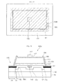
- Fig. 1 is a sectional view of a semiconductor light-emitting device according to an embodiment.
- Fig. 2 is a sectional view of the semiconductor light-emitting device taken along line II-II of Fig. 1 .
- a semiconductor light-emitting device 100 may include a light-emitting structure 135 with a compound semiconductor layer, a channel layer 140, a reflective layer 150, an adhesion layer 160, and a conductive support member 170.
- the semiconductor light-emitting device 100 may be formed using a compound semiconductor, for example, a Group III-V compound semiconductor.
- the semiconductor light-emitting device 100 may emit light of a visible-ray region, such as blue, green, and red light, and may emit light of an ultraviolet region.
- the semiconductor light-emitting device 100 may vary in shape and structure within the technical scope of embodiments.
- the light-emitting structure 135 may include a first conductivity type semiconductor layer 110, an active layer 120, and a second conductivity type semiconductor layer 130.
- the first conductivity type semiconductor layer 110 may be formed using, for example, a Group III-V compound semiconductor doped with a first conductivity type dopant.
- the Group III-V compound semiconductor may include at least one selected from the group consisting of GaN, AIN, AlGaN, InGaN, InN, InAlGaN, AlInN, AlGaAs, GaP, GaAs, GaAsP, and AlGaInP.
- the first conductivity type semiconductor layer 110 is formed of a N type semiconductor, the first conductivity type dopant may be selected from the Group V elements.
- the first conductivity type semiconductor layer 110 may be formed to have, for example, a single-layer or multi-layer structure; however, embodiments are not limited thereto.
- a top surface of the first conductivity type semiconductor layer 110 may be formed to have a light extraction structure, such as a roughness pattern 112 for light extraction efficiency.
- a transparent electrode layer and an insulating layer may be formed for current diffusion and light extraction; however, embodiments are not limited thereto.
- An electrode 115 may be disposed on the first conductivity type semiconductor layer 110.
- the electrode 115 may be, for example, a pad or may include a branch-type metal pattern connected to the pad; however, embodiments are not limited thereto.
- a top surface of the electrode 115 may be formed to have a roughness pattern; however, embodiments are not limited thereto.
- the electrode 115 may ohmic-contact the top surface of the first conductivity type semiconductor layer 110.
- the electrode 115 may be formed, for example, in a single-layer or multi-layer structure by using one or more selected from the group consisting of Cr, Ti, Al, In, Ta, Pd, Co, Ni, Si, Ge, Ag, Cu, and Au.
- the electrode 115 may be formed, for example, of at least one selected from the above materials, in consideration of the ohmic contact with the first conductivity type semiconductor layer 110, adhesive force between the metal layers, reflective characteristics, and conductive characteristics.
- the active layer 120 may be disposed under the first conductivity type semiconductor layer 110.
- the active layer 120 may be formed to have, for example, a single or multi quantum well structure.
- the active layer 120 may be formed, for example, of a Group III-V compound semiconductor to have a period of a well layer and a barrier layer.
- the active layer 120 may be formed to have an InGaN well layer/a GaN barrier layer or an InGaN well layer/an ALGaN barrier layer.
- a conductive clad layer may be formed on and/or under the active layer 120.
- the conductive clad layer may be formed of an AIGaN-based semiconductor.
- the second conductivity type semiconductor layer 130 may be disposed under the active layer 120.
- the second conductivity type semiconductor layer 130 may be formed using, for example, a Group III-V compound semiconductor doped with a second conductivity type dopant.
- the Group III-V compound semiconductor may include at least one selected from the group consisting of GaN, AIN, AlGaN, InGaN, InN, InAlGaN, AlInN, AlGaAs, GaP, GaAs, GaAsP, and AlGainP.
- the second conductivity type semiconductor layer 110 is formed of a P type semiconductor
- the second conductivity type dopant may be selected from the Group III elements.
- the second conductivity type semiconductor layer 130 may be formed to have, for example, a single-layer or multi-layer structure; however, embodiments are not limited thereto.
- the light-emitting structure 135 may further include a third conductivity type semiconductor layer 134, which may be of the first conductivity type, disposed under the second conductivity type semiconductor layer 130, as shown in Fig. 1A .
- the third conductivity type semiconductor layer may be opposite in polarity to the second conductivity type semiconductor layer 130.
- the first conductivity type semiconductor layer 110 may be a P-type semiconductor layer
- the second conductivity type semiconductor layer 130 may be a N-type semiconductor layer.
- the light-emitting structure 135 may include at least one of a N-P junction structure, a P-N junction structure, a N-P-N junction structure, and a P-N-P junction structure.
- the channel layer 140 and the reflective layer 150 may be disposed under the second conductivity type semiconductor layer 130 or the third conductivity type semiconductor layer 134.
- the second conductivity type semiconductor layer 130 is disposed as the lowermost layer of the light-emitting structure 135.
- the reflective layer 150 may contact a bottom inner side of the second conductivity type semiconductor layer 130, and the channel layer 140 may contact a bottom edge of the second conductivity type semiconductor layer 130.
- the channel layer 140 may be disposed on a channel region 105.
- the channel region 105 may be an inter-chip boundary region, for example, an edge region of the semiconductor light-emitting device.
- a top outer side of the channel layer 140 may be exposed to the outside, or may be covered by an insulating layer 190.
- a top inner side of the channel layer 140 may contact a bottom outer side of the second conductivity type semiconductor layer 130.
- the channel layer 140 may be formed, for example, in a loop, ring or frame pattern along a bottom edge of the second conductivity type semiconductor layer 130.
- the channel layer 140 may include, for example, a continuous pattern shape or a discontinuous pattern shape.
- the channel layer 140 may be formed on a path of a laser beam irradiated onto the channel region in a fabrication process.
- the channel layer 140 may be formed, for example, of at least one of oxide, nitride, or an insulating material.
- the channel layer 140 may be formed of at least one selected from the group consisting of ITO (indium tin oxide), IZO (indium zinc oxide), IZTO (indium zinc tin oxide), IAZO (indium aluminum zinc oxide), IGZO (indium gallium zinc oxide), IGTO (indium gallium tin oxide), AZO (aluminum zinc oxide), ATO (antimony tin oxide), GZO (gallium zinc oxide), SiO 2 , SiO x , SiO x N y , Si 3 N 4 , Al 2 O 3 , and TiO 2 .
- the channel layer 140 may prevent the occurrence of an electrical short even when an outer wall of the light-emitting structure 135 is exposed to moisture, thus making an LED robust against high humidity.
- the channel layer 140 is formed of a transparent material, irradiated laser beams may be transmitted in a laser scribing process, thereby preventing a metal material from being fragmented in the channel region 105 due to laser irradiation. Accordingly, an interlayer short in sidewalls of the light-emitting structure 135 may be prevented.
- the channel layer 140 may provide a predetermined interval between the reflective layer 150 and the outer wall of each layer 110/120/130 of the light-emitting structure 135.
- the channel layer 140 may be formed to a thickness of about 0.02 ⁇ m to about 5 ⁇ m.
- the thickness of the channel layer 140 may vary according to chip size.
- the reflective layer 150 may ohmic-contact the bottom surface of the second conductivity type semiconductor layer 130 and may include a reflective metal.
- the reflective layer 150 may include, for example, seed metal used for a plating process. Accordingly, the reflective layer 150 may include an ohmic layer, a seed layer, and/or a reflective layer selectively; however, embodiments are not limited thereto.
- the reflective layer 150 may extend to a bottom surface of the channel layer 140, and may be formed to contact the entire bottom surface of the channel layer 140.
- the reflective layer 150 may be formed to have a larger width and/or length than the light-emitting structure 135, thus reflecting incident light effectively. Accordingly, light extraction efficiency may be improved.
- the reflective layer 150 may be formed, for example, in a single-layer or multi-layer structure by using one selected from the group consisting of Ag, Ni, Al, Rh, Pd, Ir, Ru, Mg, Zn, Pt, Au, Hf, and a combination thereof.
- the reflective layer 150 may be formed in, for example, a multi-layer structure by using the above materials and conductive oxide materials such as IZO, IZTO, IAZO, IGZO, IGTO, AZO, and ATO.
- the reflective layer 150 may be formed in a structure, such as IZO/Ni, AZO/Ag, IZO/Ag/Ni, and AZO/Ag/Ni.
- a current blocking layer 145 may be formed in a partial region between the reflective layer 150 and the second conductivity type semiconductor layer 130.
- the current blocking layer 145 may be formed of a nonmetallic material having a lower electrical conductivity than the reflective layer 150.
- the current blocking layer 145 may be formed of at least one selected from the group consisting of ITO, IZO, IZTO, IAZO, IGZO, IGTO, AZO, ATO, ZnO, SiO 2 , SiO x , SiO x N y , Si 3 N 4 , Al 2 O 3 , and TiO 2 .
- the reflective layer 150 is formed of Ag
- the current blocking layer 145 may be formed of ITO, ZnO, or SiO 2 .
- the current blocking layer 145 may be formed of the same material as or a different material from the channel layer 140. If the current blocking layer 145 and the channel layer 140 are formed of the same material, they may be formed using the same process.
- the current blocking layer 145 may be formed to correspond to a position and pattern of the electrode 115.
- a size of the current blocking layer 145 may vary according to a degree of current diffusion.
- the current blocking layer 145 may be disposed in a structure corresponding to the electrode 115, thus diffusing a current throughout an entire region of the chip. Also, the current blocking layer 145 may be formed at an interface between the reflective layer 150 and the adhesion layer 160, or at the interface between the second conductivity type semiconductor layer 130 and the adhesion layer 160; however, embodiments are not limited thereto.
- the adhesion layer 160 may be formed to contact a bottom of the reflective layer 150 without contacting a bottom of the channel layer 140.
- the adhesion layer 160 may include, for example, a barrier metal or a bonding metal.
- the adhesion layer 160 may be formed of at least one selected from the group consisting of Ti, Au, Sn, Ni, Cr, Ga, In, Bi, Cu, Ag, and Ta.
- the conductive support member 170 may be disposed under the adhesion layer 160.
- the conductive support member 170 may be adhered to the reflective layer 150 by, for example, plating or sheet without forming the adhesion layer 160.
- the conductive support member 170 may be a base substrate formed using, for example, copper (Cu), aurum (Au), nickel (Ni), molybdenum (Mo), copper-tungsten (Cu-W), or a carrier wafer (for example, Si, Ge, GaAs, ZnO, SiC, GaN, and SiGe). Also, the conductive support member 170 may not be formed or may be formed, for example, using a conductive sheet.
- An outer side of the light-emitting structure 135 may be inclined, and the insulating layer 190 may be formed thereon.
- the insulating layer 190 may have a bottom portion disposed on the channel layer 140 and a top portion 194 disposed around the first conductivity type semiconductor layer 110. Accordingly, the insulating layer 190 may closely contact the channel layer 140 and may be formed around the light-emitting structure 135, thereby preventing an interlayer short on the outer surface of the light-emitting structure 135.
- the channel layer 140 may be formed in a band around the chip. Inner regions C3 and C4 of the channel layer 140 may correspond to a semiconductor region A1, and outer regions C1 and C2 of the channel layer 140 may be exposed outside of the chip outside of the semiconductor region A1. An inner region 140A of the channel layer 140 may be disposed at a portion of the semiconductor region A1.
- An ohmic region A2 of the reflective layer 150 may be disposed inside of the semiconductor region A1, and a width D1 of the reflective layer 150 may be smaller than a width D2 of the semiconductor region A1.
- the ohmic region A2 may be formed to have a size corresponding to a light-emitting region.
- the current blocking layer 145 may be formed to correspond to a position and pattern of the electrode 115 in the semiconductor region A1.
- the current blocking layer 145 may be disposed inside of the ohmic region A2 and the semiconductor region A1.
- a size B1 of the current blocking layer 145 may vary according to a pad or electrode pattern.
- Figs. 3 to 13 are sectional views illustrating a process for fabricating a semiconductor light-emitting device according to an embodiment.
- a substrate 101 may be loaded on a growth equipment, and a Group II to VI compound semiconductor may be formed thereon in, for example, a layer or pattern shape.
- the growth equipment may be, for example, one of a PVD (physical vapor deposition) equipment, a CVD (chemical vapor deposition) equipment, a PLD (plasma laser deposition) equipment, a dual-type thermal evaporator, a sputtering equipment, and an MOCVD (metal organic chemical vapor deposition) equipment; however, embodiments are not limited thereto.
- the substrate 101 may be formed, for example, of at least one selected from the group consisting sapphire (Al 2 0 3 ), GaN, SiC, ZnO, Si, GaP, InP, Ga 2 0 3 , conductive material, and GaAs.
- a roughness pattern may be formed in a top surface of the substrate 101.
- a layer or pattern based on a Group II to VI compound semiconductor for example, at least one of an ZnO layer (not illustrated), a buffer layer (not illustrated) and an undoped semiconductor layer (not illustrated) may be formed on the substrate 101.
- the buffer layer or the undoped semiconductor layer may be formed using, for example, a group III-V compound semiconductor.
- the buffer layer may reduce a lattice constant with the substrate 101, and the undoped semiconductor layer may be formed of an undoped GaN-based semiconductor.
- a first conductivity type semiconductor layer 110 may be formed on the substrate 101.
- An active layer 120 may be formed on the first conductivity type semiconductor layer 110.
- a second conductivity type semiconductor layer 130 may be formed on the active layer 120.
- the first conductivity type semiconductor layer 110 may be formed using, for example, a Group III-V compound semiconductor doped with a first conductivity type dopant.
- the Group III-V compound semiconductor may include at least one selected from the group consisting of GaN, AIN, AlGaN, InGaN, InN, InAlGaN, AlInN, AlGaAs, GaP, GaAs, GaAsP, and AlGalnP.
- the first conductivity type semiconductor layer 110 is formed of a N type semiconductor, the first conductivity type dopant may be selected from the Group V elements.
- the first conductivity type semiconductor layer 110 may be formed to have, for example, a single-layer or multi-layer structure; however, embodiments are not limited thereto.
- the active layer 120 may be formed on the first conductivity type semiconductor layer 110.
- the active layer 120 may be formed to have, for example, a single or multi quantum well structure.
- the active layer 120 may be formed, for example, of a Group III-V compound semiconductor to have a period of a well layer and a barrier layer, for example, a period of an InGaN well layer/a GaN barrier layer or an InGaN well layer/an AlGaN barrier layer.
- a conductive clad layer may be formed on and/or under the active layer 120.
- the conductive clad layer may be formed of an AlGaN-based semiconductor.
- the second conductivity type semiconductor layer 130 may be formed on the active layer 120.
- the second conductivity type semiconductor layer 130 may be formed using, for example, a Group III-V compound semiconductor doped with a second conductivity type dopant.
- the Group III-V compound semiconductor may include at least one selected from the group consisting of GaN, AIN, AlGaN, InGaN, InN, InAlGaN, AlInN, AlGaAs, GaP, GaAs, GaAsP, and AlGaInP.
- the second conductivity type semiconductor layer 110 is formed of a P type semiconductor
- the second conductivity type dopant may be selected from the Group III elements.
- the second conductivity type semiconductor layer 130 may be formed to have, for example, a single-layer or multi-layer structure; however, embodiments are not limited thereto.
- the first conductivity type semiconductor layer 110, the active layer 120, and the second conductivity type semiconductor layer 130 may constitute a light-emitting structure 135.
- a third conductivity type semiconductor layer 134 for example, a N-type semiconductor layer may be formed on the second conductivity type semiconductor layer 130.
- the light-emitting structure 135 may be formed to include at least one of a N-P junction structure, a P-N junction structure, a N-P-N junction structure, and a P-N-P junction structure.
- a channel layer 140 may be formed in each chip boundary region (channel region).
- the channel layer 140 may be formed around each chip region by using, for example, a mask pattern.
- the channel layer 140 may be formed, for example, in a loop, ring, or frame pattern.
- the channel layer 140 may be formed, for example, of at least one of oxide, nitride, or insulating material.
- the channel layer 140 may be formed of at least one selected from the group consisting of ITO (indium tin oxide), IZO (indium zinc oxide), IZTO (indium zinc tin oxide), IAZO (indium aluminum zinc oxide), IGZO (indium gallium zinc oxide), IGTO (indium gallium tin oxide), AZO (aluminum zinc oxide), ATO (antimony tin oxide), GZO (gallium zinc oxide), SiO 2 , SiO x , SiO x N y , Si 3 N 4 , Al 2 O 3 , and TiO 2 .
- ITO indium tin oxide
- IZO indium zinc oxide
- IZTO indium zinc tin oxide
- IAZO indium aluminum zinc oxide
- IGZO indium gallium zinc oxide
- IGTO indium gallium tin oxide
- AZO aluminum zinc oxide
- ATO antimony tin oxide
- GZO gallium zinc oxide
- the channel layer 140 may be formed using, for example, a photolithography process.
- the channel layer 140 may be formed of the above material using, for example, a sputtering process or a deposition process. If the channel layer 140 is formed of a conductive oxide material, it may serve as a current diffusion or injection layer.
- a current blocking layer 145 may be formed on the second conductivity type semiconductor layer 130.
- the current blocking layer 145 may be formed, for example, using a mask pattern.
- the current blocking layer 145 may be formed, for example, of the same material as or a different material from the channel layer 140. The formation order may vary according to such a material difference. For example, if the channel layer 140 and the current blocking layer 145 are formed of the same material, they may be formed using one process.
- the current blocking layer 145 may be formed of a material having a lower electrical conductivity than the semiconductor layer, or may be formed to have a lower electrical conductivity than the semiconductor layer.
- the current blocking layer 145 may be formed of at least one selected from the group consisting of ITO, IZO, IZTO, IAZO, IGZO, IGTO, AZO, ATO, ZnO, SiO 2 , SiO x , SiO x N y , Si 3 N 4 , Al 2 O 3 , and TiO 2 .
- the current blocking layer 145 may be formed in a desired region by, for example, using a mask pattern.
- the current blocking layer 145 may be formed to correspond to a position and pattern of a region for the electrode 115.
- the current blocking layer 145 may be formed in the same shape as an electrode pattern; however, embodiments are not limited thereto.
- the current blocking layer 145 may be formed to correspond to a pad position and/or electrode pattern.
- the current blocking layer 145 may be disposed inside of the reflective layer 150. Thus, in comparison with adjacent regions, the current blocking layer 145 may have little current flowing therethrough, thus making it possible to supply a current in a diffused manner.
- the current blocking layer 145 may be formed, for example, in a polygonal or circular pattern, or may not be formed.
- a reflective layer 150 may be formed on the second conductivity type semiconductor layer 130 to ohmic-contact the second conductivity type semiconductor layer 130.
- the reflective layer 150 may be formed on the second conductivity type semiconductor layer 130 and the current blocking layer 145 to reduce contact resistance.
- the reflective layer 150 may be formed, for example, in a single-layer or multi-layer structure by using at least one selected from the group consisting of Ag, Ni, Al, Rh, Pd, Ir, Ru, Mg, Zn, Pt, Au, Hf, and a combination thereof. Also, the reflective layer 150 may be formed, for example, in a multi-layer structure by using the above metallic material, and a conductive oxide material, such as IZO, IZTO, IAZO, IGZO, IGTO, AZO, and ATO. For example, the reflective layer 150 may be formed of IZO/Ni, AZO/Ag, IZO/Ag/Ni, or AZO/Ag/Ni. For example, the reflective layer 150 may be formed using, for example, an E-beam (electron beam) process or a sputtering process; however, embodiments are not limited thereto.
- E-beam electron beam
- the reflective layer 150 may be formed to have a stack structure of a first adhesion layer/a reflective layer/a second adhesion layer/a seed layer.
- the first and second adhesion layers may include Ni
- the reflective layer may include Ag
- the seed layer may include Cu.
- the first adhesion layer may be formed to a thickness of less than several nm
- the reflective layer may be formed to a thickness of less than hundreds of nm
- the second adhesion layer may be formed to a thickness of less than tens of nm
- the seed layer may be formed to a thickness of less than 1 ⁇ m; however, embodiments are not limited thereto.
- the reflective layer 150 may be formed to cover up to a bottom of the channel layer 140.
- the reflective layer 150 may serve as an electrode, because it may be formed of a reflective metal. Also, the reflective layer 150 and the metal materials thereon may serve as an electrode.
- an adhesion layer 160 may be formed on the reflective layer 150.
- the adhesion layer 160 may include a barrier metal or a bonding metal.
- the adhesion layer 160 may be formed of at least one selected from the group consisting of Ti, Au, Sn, Ni, Cr, Ga, In, Bi, Cu, Ag, and Ta.
- a conductive support member 170 may be formed on the adhesion layer 160.
- the conductive support member 170 may be a base substrate formed using, for example, copper (Cu), aurum (Au), nickel (Ni), molybdenum (Mo), copper-tungsten (Cu-W), or a carrier wafer (e.g., Si, Ge, GaAs, ZnO, SiC, GaN, and SiGe).
- the conductive support member 170 may be bonded to the adhesion layer 160, may be formed of a plating layer, or may be adhered by a conductive sheet.
- the adhesion layer 160 may not be formed. In this case, the conductive support member 170 may be formed on the reflective layer 150.
- the conductive support member 170 may be turned to become the base, and the substrate 101 on the light-emitting structure 135 removed.
- the substrate 101 may be removed using, for example, a Laser Lift Off (LLO) process.
- LLO Laser Lift Off
- the LLO process may irradiate a laser beam of a predetermined wavelength onto the substrate 101 to remove the substrate 101.
- another semiconductor layer for example, a buffer layer
- an air gap is present between the substrate 101 and the first conductivity type semiconductor layer 110
- the substrate 101 may be removed using a wet etchant.
- a polishing process based on ICP/RIE Inductively coupled Plasma/Reactive Ion Etching may be performed on the surface of the first conductivity type semiconductor layer 110 removed of the substrate 101.
- the channel region 105 of the light-emitting structure 135 may be removed using, for example, an isolation etching process. That is, an isolation etching process may be performed on an inter-chip boundary region. By the isolation etching process, the channel layer 140 may be exposed to the channel region 105 and a side of the light-emitting structure 135 may be inclined.
- the channel layer 140 is formed of a transparent material, laser beams irradiated in the isolation etching process or the laser scribing process may be transmitted therethrough, thereby suppressing the below metal materials (for example, the materials of the reflective layer 150, the adhesion layer 160, and the conductive support member 170) from being fragmented or projected in the laser irradiation direction.
- the channel layer 140 may transmit the laser beams, thereby making it possible to prevent metal fragments from being generated by the laser beams in the channel region 105 and to protect an outer wall of each layer of the light-emitting structure 135.
- an etching process may be performed on a top surface of the first conductivity type semiconductor layer 110 to form a roughness pattern thereon.
- the roughness pattern may improve light extraction efficiency.
- an insulating 190 may be formed around the light-emitting structure 135, wherein a bottom portion may be formed on the channel layer 140 and a top portion 194 may be formed around a top surface of the first conductivity type semiconductor layer 110.
- the insulating layer 190 may be formed around the light-emitting structure 135, thus making it possible to prevent a short between the layers 110, 120 and 130. Also, the insulating layer 180 and the channel layer 140 may prevent moisture from infiltrating into the chip.
- An electrode 115 may be formed on the first conductivity type semiconductor layer 110.
- the electrode 115 may be formed in a predetermined pattern.
- the forming of the insulating layer 190 and the electrode 115 may be performed before or after chip separation; however, embodiments are not limited thereto.
- the electrode 115 may be formed to correspond to a position of the current blocking layer 145, and a roughness pattern may be formed in a top surface of the electrode 115; however, embodiments are not limited thereto.
- the resulting structure may be separated into separate chip units by a chip boundary.
- the chip separation may be performed, for example, a laser or a breaking process.
- a sectional view taken along a line II-II of Fig. 13 is the same as Fig. 2 .
- Fig. 14 is a sectional view of a semiconductor light-emitting device according to another embodiment. In describing the embodiment of Fig. 14 , repetitive description overlapping with the embodiment of Fig. 1 has been omitted.
- a semiconductor light-emitting device 100A may include a channel layer 140, a current blocking layer 145, and a reflective layer 151 that are disposed under a second conductivity type semiconductor layer 130.
- the channel layer 140, the current blocking layer 145, and the reflective layer 151 may be formed not to overlap each other.
- An adhesion layer 160 and/or a conductive support member 170 may be formed under the channel layer 140, the reflective layer 151, and the current blocking layer 145.
- the adhesion layer 160 may contact bottoms of the channel layer 140, the reflective layer 151, and the current blocking layer 145.
- the channel layer 140 may provide a predetermined interval between the adhesion layer 160 and an outside or outer wall of the light-emitting structure 135.
- the reflective layer 151 may ohmic-contact the second conductivity type semiconductor layer 130 in an inner region of the channel layer 140.
- the current blocking layer 145 may be formed in a pattern corresponding to the electrode 115 in the reflective layer 151.
- the reflective layer 151 may be formed only in the ohmic contact region, so that the ohmic contact region and the reflective region may be formed to have the same size.
- Fig. 15 is a sectional view of a semiconductor light-emitting device according to another embodiment. In describing the embodiment of Fig. 15 , repetitive description overlapping with the embodiment of Fig. 1 has been omitted.
- a semiconductor light-emitting device 100B may have a modified adhesion structure of a reflective layer 152 and a channel layer 140 under a light-emitting structure 135.
- An outer end 152A of the reflective layer 152 may overlap with an inner end 140A of the channel layer 140 by a predetermined amount or distance (or width) D3.
- the outer end 152A of the reflective layer 152 may be spaced apart by a predetermined distance D2 from the outer wall of the chip. Therefore, it may not be exposed at the outer wall of the chip, thus making it possible to overcome the problem of exfoliation at the outer wall of the chip.
- the overlap distance D3 of the reflective layer 152 with the bottom of the channel layer 140 may be less than approximately 80% of the bottom width (D2+D3) of the channel layer 140. Because the overlap distance D3 of the reflective layer 152 is reduced, the problem of a decrease in adhesive force by the material of the reflective layer 152 may be reduced. For example, if the width (D2+D3) of the channel layer 140 is about 75 ⁇ m, the overlap distance D3 may be less than about 6 ⁇ m.
- Fig. 16 is a sectional view of a semiconductor light-emitting device according to another embodiment. In describing the embodiment of Fig. 16 , repetitive description overlapping with the embodiment of Fig. 1 has been omitted.
- a semiconductor light-emitting device 100C may have a stack structure of a channel layer 141 and a capping layer 155 in a channel region 105.
- An inner side of the channel layer 141 may contact the bottom of the second conductivity type semiconductor layer 130 and an outer side of the channel layer 141 may be exposed to the outside of the chip.
- the channel layer 141 may be formed, for example, of oxide-based materials in this embodiment.
- the channel layer 141 may be formed of at least one selected from the group consisting of ITO, IZO, IZTO, IAZO, IGZO, IGTO, AZO, ATO, GZO, SiO 2 , SiOx, Al 2 O 3 , and TiO 2 .
- the capping layer 155 may be formed, for example, of a metal having a good adhesive force with an oxide, for example, at least one selected from the group consisting of Ti, Ni, Pt, Pd, Cu, Al, Ir, and Rh. That is, the capping layer 155 may be, for example, a single-layer or multi-layer adhesive layer using the above materials, which may increase the adhesive force between the metal and the oxide material, thus reducing the problem of exfoliation at the outer wall of the chip.
- the capping layer 155 may be formed to a thickness of less than a few hundreds of nm.
- the capping layer 155 may be formed using, for example, an e-beam deposition process or a sputtering process; however, embodiments are not limited thereto.
- the capping layer 155 may be formed between the reflective layer 150 and the bottom surface of the channel layer 141 to increase the adhesive force of the reflective layer 150, thus reducing the problem of interlayer exfoliation at the outer wall of the chip.
- Fig. 17 is a sectional view of a semiconductor light-emitting device according to another embodiment.
- Fig. 18 is a sectional view taken along a line XVIII-XVIII of Fig. 17 .
- repetitive description overlapping with the above described embodiments has been omitted.
- a semiconductor light-emitting device 100D may have a capping layer 155 surrounding a bottom edge of a channel layer 141.
- a channel layer 141 may be formed at a bottom outer side of the light-emitting structure 135, and the capping layer 155 may be disposed under the channel layer 141.
- the channel layer 141 may be formed, for example, in a ring or band pattern with a predetermined width along the chip.
- the capping layer 155 may be formed in a bottom surface and an inner surface of the channel layer 141. As illustrated in Fig.
- an inner end 155A of the capping layer 155 may be formed, for example, in a ring or band pattern along a region between the reflective layer 150 and the channel layer 141.
- 'E1' denotes a semiconductor region.
- the second conductivity type semiconductor layer 130 may contact the reflective layer 150, the channel layer 141, a current blocking layer 145, and the capping layer 155. Therefore, the second conductivity type semiconductor layer 130 may be protected by the channel layer 141 outside of the chip and may be supplied with a current through the reflective layer 150 and the capping layer 155 inside of the chip.
- Fig. 19 is a modification of Fig. 18 .
- an end portion 155B of the capping layer 155 may be formed to have a plurality of patterns (not a single pattern). That is, the end portion 155B of the capping layer 155 may be separated at regular intervals or at irregular intervals to contact the bottom surface of the second conductivity type semiconductor layer 130 in a roughness structure. This adhesion structure can increase the adhesive force of the capping layer 155 and the reflective layer 150 with respect to the channel layer 141. Some or all of the capping layers 155 may be formed to have a plurality of patterns.
- Fig. 20 is a sectional view of a semiconductor light-emitting device according to another embodiment. In describing the embodiment of Fig. 20 , repetitive description overlapping with the above described embodiments has been omitted.
- a semiconductor light-emitting device 100E may have a modified adhesion structure of a channel layer 141, a capping layer 155, and a reflective layer 150 disposed in a channel region 105.
- the reflective layer 150 may be formed to be narrower than the reflective layer of Fig. 16 .
- An outer end 152 of the reflective layer 150 may overlap with the bottom of an inner end 143 of the capping layer 155 by a predetermined amount or distance (or width) D5.
- the overlap distance D5 may be less than approximately 80% of the width (D4+D5) of the capping layer 155, and an outer end of the reflective layer 150 may be spaced apart by a predetermined distance D4 from the outer wall of the chip.
- the capping layer 155 may be formed under the channel layer 141 to have the same width (D4+D5) as the channel layer 144, or may be formed to be narrower than the channel layer 141.
- Fig. 21 is a sectional view of a semiconductor light-emitting device according to another embodiment. In describing the embodiment of Fig. 21 , repetitive description overlapping with the above described embodiments has been omitted.
- a semiconductor light-emitting device 100F may include a channel layer 141, a capping layer 155, and a reflective layer 150 that are formed around the bottom of a light-emitting structure 135.
- An inner top surface of the channel layer 141 may contact the bottom surface of the second conductivity type semiconductor layer 130, and the bottom surface and the inner surface of the channel layer 141 may be covered with the capping layer 155.
- An inner end 155A of the capping layer 155 may contact the bottom surface of the second conductivity type semiconductor layer 130 to supply a current.
- An outside or outer edge of the reflective layer 150 may contact the capping layer 155 and may not contact the channel layer 141, thus improving adhesive force for the outside of the reflective layer 150.
- an end portion 152 of the reflective layer 152 may be disposed to overlap with the bottom of the capping layer 155 by a predetermined distance D6.
- the overlap distance D6 may be less than approximately 80% of the width of the channel layer 141. Because the end portion 152 of the reflective layer 152 may be disposed to overlap with the bottom of the capping layer 155, the adhesive force of the reflective layer 152 with the end portion 152 may be increased.
- Fig. 22 is a sectional view of a semiconductor light-emitting device according to another embodiment. In describing the embodiment of Fig. 22 , repetitive description overlapping with the above described embodiments has been omitted.
- a semiconductor light-emitting device 200 may include a light-emitting structure 135, a channel layer 240, a current blocking layer 245, a reflective layer 250, an adhesion layer 260, a conductive support member 270, and an ohmic layer 280.
- the channel layer 240 may be disposed around the bottom of the second conductivity type semiconductor layer 130, and the ohmic layer 280 and the current blocking layer 245 may be disposed inside the second conductivity type semiconductor layer 130.
- the channel layer 240 may be the same as that of the embodiment of Fig. 1 .
- the current blocking layer 245 may be formed between the second conductivity type semiconductor layer 130 and the ohmic layer 280 to diffuse a current.
- the ohmic layer 280 may be formed between the reflective layer 250 and the second conductivity type semiconductor layer 130 of a light-emitting structure 135.
- the ohmic layer 280 may be formed, for example, of a conductive oxide material selected from the group consisting of ITO, IZO, IZTO, IAZO, IGZO, IGTO, AZO, ATO, GZO, and a combination thereof. That is, the ohmic layer 280 may contact the bottom surface of the second conductivity type semiconductor layer 130.
- the ohmic layer 280 may be formed, for example, using a sputtering process (for example, radio-frequency-magnetron sputtering) or a deposition process; however, embodiments are not limited thereto.
- the ohmic layer 280 may be formed to a thickness of less than several nm; however, embodiments are not limited thereto.
- the ohmic layer 280 may contact bottoms of the channel layer 240, the second conductivity type semiconductor layer 130, and the current blocking layer 245 to supply a current, applied through the adhesion layer 260, to the second conductivity type semiconductor layer 130.
- the reflective layer 250 may be formed to have a stack structure of a first adhesion layer/a reflective layer/a second adhesion layer/a seed layer.
- the first and second adhesion layers may include Ni
- the reflective layer may include Ag
- the seed layer may include Cu.
- the first adhesion layer may be formed to a thickness of less than several nm
- the reflective layer may be formed to a thickness of less than hundreds of nm
- the second adhesion layer may be formed to a thickness of less than tens of nm
- the seed layer may be formed to a thickness of less than 1 ⁇ m; however, embodiments are not limited thereto.
- Fig. 23 is a sectional view taken along line XXIII-XXIII of Fig. 22 .
- an inner region 240A of the channel layer 240 may be disposed outside of a semiconductor region A1, and an ohmic region A4 of an ohmic layer 280 and a region of a current blocking layer 245 may be disposed inside of the semiconductor region A1.
- a width D12 of the semiconductor region A1 may be larger than a width D11 of the ohmic layer 280.
- the distances D14 and D13 of the inner region and the outer region of the channel layer 240 may be equal to or different from each other; however, embodiments are not limited thereto.
- Fig. 24 is a sectional view of a semiconductor light-emitting device according to another embodiment. In describing the embodiment of Fig. 24 , repetitive description overlapping with the above described embodiments has been omitted.
- a semiconductor light-emitting device 201 may have a modified reflective layer 250.
- the reflective layer 250 may be disposed only in a region not a channel region 105 of the ohmic layer 280 (that is, only in an ohmic region) to reflect incident light.
- An outer end 251 of the reflective layer 250 may not be exposed outside of the chip.
- Fig. 25 is a sectional view of a semiconductor light-emitting device according to another embodiment. In describing the embodiment of Fig. 25 , repetitive description overlapping with the above described embodiments has been omitted.
- a semiconductor light-emitting device 201A may have a conductive oxide-based ohmic layer 280 formed to ohmic-contact a bottom of a light-emitting structure 135, and a transparent channel layer 240 formed at an outside of the light-emitting structure 135.
- An end portion 251 of the reflective layer 250 may be formed to overlap with a channel region 105 by a predetermined distance D16.
- the overlap distance D16 may be less than approximately 80% of the bottom width (D15+D16) of the channel layer 240. That is, as illustrated in Figs. 24 and 26 , some or an entire reflective layer 250 may contact the ohmic layer 280 under a region of the channel layer 240.
- Fig. 26 is a sectional view of a semiconductor light-emitting device according to another embodiment. In describing the embodiment of Fig. 26 , repetitive description overlapping with the above described embodiments has been omitted.
- a semiconductor light-emitting device 202 may have a conductive oxide-based ohmic layer 280 formed to ohmic-contact a bottom of a light-emitting structure 135, and a transparent channel layer 240 formed at the outside of the light-emitting structure 135.
- a reflective layer 250 may be formed under the ohmic layer 280, and a capping layer 255 may be formed between the ohmic layer 280 and the reflective layer 250.
- the capping layer 255 may be formed, for example, of a metal having a good adhesive force with an oxide, for example, one or more selected from the group consisting of Ti, Ni, Pt, Pd, Cu, Al, Ir, and Rh. That is, the capping layer 255 may be, for example, a single-layer or multi-layer adhesion layer using the above materials, which increases the adhesive force between the metal and the oxide material, thus reducing exfoliation at the outer wall of the chip.
- the capping layer 255 may be formed between an outer bottom surface of the ohmic layer 240 and an outer top surface of the reflective layer 250 to increase the adhesive force of the reflective layer 250 with respect to the outside, thus reducing interlayer exfoliation at the outer wall of the chip.
- the outside of the reflective layer 250 may be formed to extend to the outside of the chip along the bottom surface of the capping layer 255.
- Fig. 27 is a sectional view of a semiconductor light-emitting device according to another embodiment. In describing the embodiment of Fig. 27 , repetitive description overlapping with the above described embodiments has been omitted.
- a semiconductor light-emitting device 203 may include an ohmic layer 280 formed under a channel layer 240, a capping layer 255 formed under the ohmic layer 280, and a reflective layer 250 formed under the capping layer 255 in a channel region 105.
- the capping layer 255 may be formed around an outer edge of the ohmic layer 280 to reduce a contact area with respect to the reflective layer 250.
- the ohmic layer 280 may be formed, for example, of a conductive oxide material.
- the capping layer 255 may be formed in an outer channel region 105 between the ohmic layer 280 and the reflective layer 250.
- the capping layer 255 may be formed, for example, of a metal having a good adhesive force with respect to the oxide material.
- An inner end 255A of the capping layer 255 may be formed to extend to a portion of an ohmic contact region of the ohmic layer 280.
- the outside of the ohmic layer 280 may cover an edge of the channel layer 240, and the capping layer 255 may extend to a cover region of the ohmic layer 280 with respect to the channel layer 240.
- Fig. 28 is a sectional view of a semiconductor light-emitting device according to another embodiment. In describing the embodiment of Fig. 28 , repetitive description overlapping with the above described embodiments has been omitted.
- a semiconductor light-emitting device 204 may have a stack structure of a channel layer 240, a capping layer 255, and an outer end 281 of an ohmic layer 280 disposed under the channel layer 240 in a channel region 105.
- the outer end 281 of the ohmic layer 280 may extend to an inner bottom side of the channel layer 240 and may not be exposed outside of the chip.
- the capping layer 255 may be formed under a bottom outside of the channel layer 240 and the outer end 281 of the ohmic layer 280. The capping layer 255 may contact bottoms of the ohmic layer 280 and the channel layer 240, thereby improving adhesive force of the reflective layer 250.
- Fig. 29 is a sectional view of a semiconductor light-emitting device according to another embodiment.
- repetitive description overlapping with the above described embodiments has been omitted.
- a semiconductor light-emitting device 204A may have a modified capping layer 255 of the channel region 105 in comparison with the semiconductor light-emitting device of Fig. 28 .
- the capping layer 255 may be formed under a bottom outside of the channel layer 240 and an outer end 281 of the ohmic layer 280, and its inner end 255A may be formed to extend up a portion of an ohmic contact region of the ohmic layer 280.
- the ohmic contact region of the ohmic layer 280 may be a region contacting the second conductivity type semiconductor layer 130, and the ohmic layer 280 may be disposed between the end 255A of the capping layer 255 and the second conductivity type semiconductor layer 130.
- the reflective layer 250 may contact the bottom of the capping layer 255 and may be exposed to the outer wall of the chip.
- the capping layer 255 may contact outer bottoms of the ohmic layer 280 and the channel layer 240, thereby improving adhesive force of the reflective layer 250.
- Fig. 30 is a sectional view of a semiconductor light-emitting device according to another embodiment. In describing the embodiment of Fig. 30 , repetitive description overlapping with the embodiment of Fig. 29 has been omitted.
- a semiconductor light-emitting device 205 may include an ohmic layer 280 formed at the bottom surface of a channel layer 240, a capping layer 255 formed under the outside of the ohmic layer 280, and a reflective layer 250 formed at a portion of the bottom of the capping layer 255.
- An end portion 250A of the reflective layer 250 may extend to a bottom inside of the capping layer 255 and may not be exposed to the outer wall of the chip. Accordingly, a decrease in adhesive force in the end portion 250A of the reflective layer 250 may be prevented.
- Fig. 31 is a sectional view of a semiconductor light-emitting device according to another embodiment. In describing the embodiment of Fig. 31 , repetitive description overlapping with the embodiment of Fig. 30 has been omitted.
- a semiconductor light-emitting device 205A may include an ohmic layer 280 formed at the bottom surface of a channel layer 240, a capping layer 255 formed under the outside of the ohmic layer 280, and a reflective layer 250 extending to the bottom inside of the capping layer 255.
- the reflective layer 250 may be formed under the ohmic layer 280.
- An end portion 250A of the reflective layer 250 may extend to a bottom inside of the capping layer 255 and may not be exposed to the outer wall of the chip. Accordingly, a decrease in the adhesive force in the end portion 250A of the reflective layer 250 may be prevented.
- An inner end 255A of the capping layer 255 may be formed to extend an ohmic contact region of the ohmic layer 280 to increase the contact area between the ohmic layer 280 and the reflective layer 250.
- the end portion 250A of the reflective layer 250 may be disposed to overlap with the bottom of the channel layer 240, and may be formed to have a width less than approximately 80% of the width of the channel layer 240.
- Fig. 32 is a sectional view of a semiconductor light-emitting device according to another embodiment. In describing the embodiment of Fig. 32 , repetitive description overlapping with the embodiment of Fig. 32 has been omitted.
- a semiconductor light-emitting device 206 may include a channel layer 240 formed under the outside of a light-emitting structure 135, an ohmic layer 280 formed under the second conductivity type semiconductor layer 130 and inside of the channel layer 240, and a capping layer 255 formed under the outside of the channel layer 240 and the outside of the ohmic layer 280.
- a reflective layer 250 may be formed under the ohmic layer 280 and inside of the capping layer 255.
- the reflective layer 250 may extend to an inner bottom of the capping layer 255.
- the extending portion 250A may have a region overlapping with the channel layer 240, and a width of the overlap region may be less than approximately 80% of the bottom width of the channel layer 240.
- An adhesive layer 260 and the outside of the reflective layer 250 may contact the bottom of the capping layer 255, thereby improving adhesive force of the reflective layer 250 and the adhesion layer 260.
- Fig. 33 is a sectional view of a semiconductor light-emitting device according to another embodiment. In describing the embodiment of Fig. 33 , repetitive description overlapping with the embodiment of Fig. 32 has been omitted.
- a semiconductor light-emitting device 206A may include a channel layer 240 formed under an outside of a light-emitting structure 135, an ohmic layer 280 formed under the second conductivity type semiconductor layer 130 and inside of the channel layer 240, and a capping layer 255 formed under the outside of the channel layer 240 and the outside 281 of the ohmic layer 280.
- a reflective layer 250 may be formed under the ohmic layer 280 and inside of the capping layer 255.
- the reflective layer 250 may extend to the inner bottom of the capping layer 255.
- the extending portion 250A may have a region spatially overlapping with the channel layer 240, and a width of the overlap region may be less than approximately 80% of a bottom width of the channel layer 240.
- An adhesion layer 260 and the outside of the reflective layer 250 may contact the bottom of the capping layer 255, thereby improving adhesive force of the reflective layer 250 and the adhesion layer 260.
- An end portion 255A of the capping layer 255 may extend to an ohmic contact region of the ohmic layer 280 to reduce the contact area between the reflective layer 250 and the ohmic layer 280. Accordingly, the capping layer 255 may improve adhesive force between the reflective layer 250, the ohmic layer 280, and the adhesion layer 260.
- Figs. 34 to 42 are sectional views of semiconductor light-emitting devices according to additional embodiments. In describing the embodiment of Fig. 34 , repetitive description overlapping with the embodiment of Fig. 1 has been omitted.
- roughness patterns P1 and P2 are formed on top and bottom surfaces of a channel layer 140 to increase adhesive force according to an increase in contact area.
- the top roughness pattern P1 of the channel layer 140 contacts the second conductivity type semiconductor layer 130, and bottom roughness pattern P2 of the channel layer 140 contacts a top surface of the reflective layer 150. Accordingly, contact area and adhesive force between the second conductivity type semiconductor layer 130 and the reflective layer 150 may be improved.
- the top and bottom roughness patterns P1 and P2 of the channel layer 140 may change a critical angle of light output/input through the surface.
- the roughness patterns P1 and P2 may have, for example, a prism, stripe, convexo-concave, or triangular sectional shape, which may vary within the technical scope of the inventive concept.
- the top roughness pattern P1 may be formed, for example, by etching a bottom surface of the second conductivity type semiconductor layer 130 in a pattern shape.
- the bottom roughness pattern P2 may be formed, for example, by etching a bottom surface of the channel layer 140.
- a roughness pattern P2 may be formed on a bottom surface of a channel layer 140 to increase the adhesive force according to an increase in contact area with the reflective layer 150.
- the roughness pattern P2 of the channel layer 140 may change a critical angle of light output/input through the surface.
- a roughness pattern P2 may be formed on an outer top and/or bottom surface(s) of a reflective layer 150 to increase adhesive force according to an increase in contact area with the adhesion layer 160 and the channel layer 140 adjacent to the outside the reflective layer 150.
- the top roughness pattern P2 of the channel layer 140 may change a critical angle of light output/input through the surface, and the bottom roughness pattern P3 may improve adhesive force with respect to the adhesion layer 160.
- a bottom of a channel layer 140A may be etched to form a sawtooth-wave roughness pattern, and an outside 150A of the reflective layer 150 may be formed to have a convexo-concave roughness pattern along a bottom surface of the channel layer 140.
- an etching depth may be equal to about a thickness of the channel layer 140A, and the etching angle may be inclined or perpendicular.
- a bottom of a channel layer 140 may be etched to form a convexo-concave or square-wave roughness pattern P5, and an outside of the reflective layer 150 may be formed to have a convexo-concave or square-wave roughness pattern P6 along a bottom surface of the channel layer 140.
- an etching depth may be less than a thickness of the channel layer 140, and an etching shape may be polygonal and hemispheric.
- a bottom of a channel layer 140B may be etched to form a convexo-concave or square-wave roughness pattern P7, and an outside 150B of the reflective layer 150 may be formed to have a convexo-concave or square-wave roughness pattern along a bottom surface of the channel layer 140B.
- the channel layer 140B may be divided into a plurality of regions; however, embodiments are not limited thereto.
- An etching depth may be less than a thickness of the channel layer 140B, an etching shape may be polygonal and hemispheric, a concave interval and/or a convex interval may be equal to or different from each other.
- a bottom of a channel layer 240 may be etched to form a roughness pattern P8, and an outside of an ohmic layer 280 may be formed to have a roughness pattern along the roughness pattern P8.
- the roughness pattern P8 may increase contact area between two adjacent layers to improve adhesive force.
- a bottom of a channel layer 240A may be etched to form a sawtooth-wave roughness pattern, and an outside 280A of an ohmic layer 280 may be formed to have a roughness pattern along a bottom surface of the channel layer 240.
- An etching depth may be less than a thickness of the channel layer 140A, and an etching angle may be inclined or perpendicular.
- roughness patterns P11 and P12 may be formed on top and bottom surfaces of a channel layer 240.
- the top roughness pattern P11 of the channel layer 140 may contact a bottom outside of the second conductivity type semiconductor layer 130, and bottom roughness pattern P12 of the channel layer 140 may contact a top surface of the ohmic layer 280. Accordingly, contact area and adhesive force between the second conductivity type semiconductor layer 130 and the ohmic layer 280 may be improved.
- the roughness patterns P11 and P12 may have, for example, a prism, stripe, convexo-concave, and sawtooth-wave (for example, triangular sectional) shape, which may vary within the technical scope of the inventive concept.
- the top roughness pattern P11 may be formed, for example, by etching a bottom surface of the second conductivity type semiconductor layer 130 in a pattern shape.
- the bottom roughness pattern P12 may be formed by, for example, etching a bottom surface of the channel layer 240.
- An outer bottom surface of the reflective layer 250 may have a roughness pattern P13 due to the ohmic layer 280, thereby changing a critical angle of input/output light.
- the roughness patterns P12 and P13 of the reflective layer 250 and the channel layer 240 may be formed on some or all of the surfaces of each layer.
- Fig. 43 is sectional view of a light-emitting device package according to an embodiment.
- a light-emitting device package according to an embodiment 28 may include a body 20, a first lead electrode 31, a second lead electrode 32, a semiconductor light-emitting device 100, and a molding member 40.
- the first lead electrode 31 and the second lead electrode 32 may be disposed on the body 20.
- the semiconductor light-emitting device 100 disposed on the body 20 may be electrically connected to the first lead electrode 31 and the second lead electrode 32.
- the molding member 40 may be configured to mold the semiconductor light-emitting device 100.
- the body 20 may be formed to include a silicon material, a synthetic resin, or a metallic material.
- An inclined surface may be formed around the semiconductor light-emitting device 100.
- the first lead electrode 31 and the second lead electrode 32 may be electrically disconnected from each other, and may provide power to the semiconductor light-emitting device 100. Also, the first lead electrode 31 and the second lead electrode 32 may reflect light emitted from the semiconductor light-emitting device 100, thus increasing light efficiency. Also, the first lead electrode 31 and the second lead electrode 32 may serve to discharge heat generated by the semiconductor light-emitting device 100.
- the semiconductor light-emitting device 100 may be disposed on the body 20, or may be disposed on the first lead electrode 31 or the second lead electrode 32.
- the semiconductor light-emitting device 100 may be electrically connected by, for example, a wire to the first lead electrode 31, and may be connected to the second lead electrode 32 in a die-bonding configuration.
- the molding member 40 may mold the semiconductor light-emitting device 100 to protect the semiconductor light-emitting device 100. Also, a fluorescent material may be included in the molding member 40 to change a wavelength of light emitted from the semiconductor light-emitting device 100.
- the semiconductor light-emitting device according to the embodiments disclosed herein may be packaged in a semiconductor substrate, an insulating substrate or a ceramic substrate (such as a resin material or silicon), and may be used as a light source of a indication device, an illumination device or a display device.
- embodiments disclosed herein may improve the light extraction efficiency. Also, the embodiments disclosed herein may overcome the problem of adhesion between the layers disposed under the light-emitting structure.
- the embodiments disclosed herein may overcome the problem of the adhesion between the metal and the nonmetal in the channel region under the light-emitting structure. Furthermore, the embodiments disclosed herein may overcome the problem of the interlayer exfoliation in the channel region by improving the adhesive force between the reflective material and the oxide under the light-emitting structure. Additionally, the embodiments disclosed herein may improve reliability of the semiconductor light-emitting device.
- the embodiments disclosed herein are applicable to any light-emitting device that provides light.
- Embodiments disclosed herein provide a semiconductor light-emitting device capable of improving adhesive force between layers disposed under a light-emitting structure including a copound semiconductor layer and a method for fabricating the same.
- a semiconductor light-emitting device may include a light-emitting structure including a plurality of compound semiconductor layers; an electrode on the compound semiconductor layer; a reflective layer under the compound semiconductor layer; a conductive support member under the reflective layer; and a channel layer along a bottom edge of the compound semiconductor layer.
- a method for fabricating a semiconductor light-emitting device may include forming a plurality of compound semiconductor layers on a substrate; forming a channel layer along a top edge of the compound semiconductor layer; forming a reflective layer on the compound semiconductor layer; turning the reflective layer to the base and removing the substrate; etching the compound semiconductor layer to expose the channel layer; and forming an electrode on the compound semiconductor layer.
- any reference in this specification to "one embodiment,” “an embodiment,” “example embodiment,” etc. means that a particular feature, structure, or characteristic described in connection with the embodiment is included in at least one embodiment of the invention.
- the appearances of such phrases in various places in the specification are not necessarily all referring to the same embodiment.
Abstract
Description
- A semiconductor light-emitting device and a method for fabricating the same are disclosed herein.
- Semiconductor light-emitting devices and methods for fabricating the same are known. However, they suffer from various disadvantages.
- Embodiments will be described in detail with reference to the following drawings in which like reference numerals refer to like elements, and wherein:
-
Fig. 1 is a sectional view of a semiconductor light-emitting device according to an embodiment; -
Fig. 1A is a sectional view of a semiconductor light-emitting device according to another embodiment; -
Fig. 2 is a sectional view of the semiconductor light-emitting device taken along a line II-II ofFig. 1 ; -
Figs. 3 to 13 are sectional views illustrating a process for fabricating a semiconductor light-emitting device according to an embodiment; -
Fig. 14 is a sectional view of a semiconductor light-emitting device according to another embodiment; -
Fig. 15 is a sectional view of a semiconductor light-emitting device according to another embodiment; -
Fig. 16 is a sectional view of a semiconductor light-emitting device according to another embodiment; -
Fig. 17 is a sectional view of a semiconductor light-emitting device according to another embodiment; -
Fig. 18 is a sectional view of the semiconductor light-emitting device taken along a line XVIII-XVIII ofFig. 17 ; -
Fig. 19 is a sectional view illustrating a modified embodiment of the semiconductor light-emitting device ofFig. 18 ; -
Fig. 20 is a sectional view of a semiconductor light-emitting device according to another embodiment; -
Fig. 21 is a sectional view of a semiconductor light-emitting device according to another embodiment; -
Fig. 22 is a sectional view of a semiconductor light-emitting device according to another embodiment; -
Fig. 23 is a sectional view of the semiconductor light-emitting device taken along a line XXIII-XXIII ofFig. 22 ; -
Fig. 24 is a sectional view of a semiconductor light-emitting device according to another embodiment; -
Fig. 25 is a sectional view of a semiconductor light-emitting device according to another embodiment; -
Fig. 26 is a sectional view of a semiconductor light-emitting device according to another embodiment; -
Fig. 27 is a sectional view of a semiconductor light-emitting device according to another embodiment; -
Fig. 28 is a sectional view of a semiconductor light-emitting device according to another embodiment; -
Fig. 29 is a sectional view of a semiconductor light-emitting device according to another embodiment; -
Fig. 30 is a sectional view of a semiconductor light-emitting device according to another embodiment; -
Fig. 31 is a sectional view of a semiconductor light-emitting device according to another embodiment; -
Fig. 32 is a sectional view of a semiconductor light-emitting device according to another embodiment; -
Fig. 33 is a sectional view of a semiconductor light-emitting device according to another embodiment; -
Figs. 34 to 42 are sectional views of semiconductor light-emitting devices according to additional embodiments; and -
Fig. 43 is a sectional view of a light-emitting device package according to an embodiment. - Reference will now be made in detail to embodiments, examples of which are illustrated in the accompanying drawings. In the descriptions of embodiments, it should be understood that when a layer (or film), a region, a pattern, or a structure is referred to as being "on/under" a substrate, a layer (or film), a region, a pad, or patterns, it may be directly on the substrate, the layer (or film), the region, the pad, or the patterns, or intervening layers may also be present. Further, the reference about 'on' and 'under' each layer will be made on the basis of the drawings. In the drawings, dimensions of each of element may be exaggerated for clarity of illustration, and the dimensions of each of the elements may be different from the actual dimension of each of the elements.
- Hereinafter, embodiments will be described with reference to the accompanying drawings. Where possible, like reference numerals have been used to indicate like elements.
- Due to their physical and chemical characteristics, Group III-V nitride semiconductors are being utilized as core materials for light-emitting devices, such as light-emitting diodes (LEDs) and laser diodes (LDs). An example of the Group III-V nitride semiconductors is a nitride semiconductor with a composition equation of InxAlyGa1-x-yN (0≤x≤1, 0≤y≤1, 0≤x+y≤1).
- An LED is a kind of semiconductor device that is used as a light source or uses the characteristics of compound semiconductors to converts electricity into light to exchange signals. Nitride semiconductor based LEDs or LDs are widely used in light-emitting devices, and are applied as light sources for various products, such as keypad light-emitting units of mobile phones, electric light panels, and illumination devices.
-
Fig. 1 is a sectional view of a semiconductor light-emitting device according to an embodiment.Fig. 2 is a sectional view of the semiconductor light-emitting device taken along line II-II ofFig. 1 . - Referring to
Figs. 1 and2 , a semiconductor light-emitting device 100 according to an embodiment may include a light-emitting structure 135 with a compound semiconductor layer, achannel layer 140, areflective layer 150, anadhesion layer 160, and aconductive support member 170. The semiconductor light-emitting device 100 may be formed using a compound semiconductor, for example, a Group III-V compound semiconductor. The semiconductor light-emitting device 100 may emit light of a visible-ray region, such as blue, green, and red light, and may emit light of an ultraviolet region. The semiconductor light-emitting device 100 may vary in shape and structure within the technical scope of embodiments. - The light-
emitting structure 135 may include a first conductivitytype semiconductor layer 110, anactive layer 120, and a second conductivitytype semiconductor layer 130. The first conductivitytype semiconductor layer 110 may be formed using, for example, a Group III-V compound semiconductor doped with a first conductivity type dopant. For example, the Group III-V compound semiconductor may include at least one selected from the group consisting of GaN, AIN, AlGaN, InGaN, InN, InAlGaN, AlInN, AlGaAs, GaP, GaAs, GaAsP, and AlGaInP. For example, if the first conductivitytype semiconductor layer 110 is formed of a N type semiconductor, the first conductivity type dopant may be selected from the Group V elements. The first conductivitytype semiconductor layer 110 may be formed to have, for example, a single-layer or multi-layer structure; however, embodiments are not limited thereto. A top surface of the first conductivitytype semiconductor layer 110 may be formed to have a light extraction structure, such as aroughness pattern 112 for light extraction efficiency. Also, a transparent electrode layer and an insulating layer may be formed for current diffusion and light extraction; however, embodiments are not limited thereto. - An
electrode 115 may be disposed on the first conductivitytype semiconductor layer 110. Theelectrode 115 may be, for example, a pad or may include a branch-type metal pattern connected to the pad; however, embodiments are not limited thereto. A top surface of theelectrode 115 may be formed to have a roughness pattern; however, embodiments are not limited thereto. - The
electrode 115 may ohmic-contact the top surface of the first conductivitytype semiconductor layer 110. Theelectrode 115 may be formed, for example, in a single-layer or multi-layer structure by using one or more selected from the group consisting of Cr, Ti, Al, In, Ta, Pd, Co, Ni, Si, Ge, Ag, Cu, and Au. Theelectrode 115 may be formed, for example, of at least one selected from the above materials, in consideration of the ohmic contact with the first conductivitytype semiconductor layer 110, adhesive force between the metal layers, reflective characteristics, and conductive characteristics. - The
active layer 120 may be disposed under the first conductivitytype semiconductor layer 110. Theactive layer 120 may be formed to have, for example, a single or multi quantum well structure. Theactive layer 120 may be formed, for example, of a Group III-V compound semiconductor to have a period of a well layer and a barrier layer. For example, theactive layer 120 may be formed to have an InGaN well layer/a GaN barrier layer or an InGaN well layer/an ALGaN barrier layer. - A conductive clad layer may be formed on and/or under the
active layer 120. For example, the conductive clad layer may be formed of an AIGaN-based semiconductor. - The second conductivity
type semiconductor layer 130 may be disposed under theactive layer 120. The second conductivitytype semiconductor layer 130 may be formed using, for example, a Group III-V compound semiconductor doped with a second conductivity type dopant. For example, the Group III-V compound semiconductor may include at least one selected from the group consisting of GaN, AIN, AlGaN, InGaN, InN, InAlGaN, AlInN, AlGaAs, GaP, GaAs, GaAsP, and AlGainP. For example, if the second conductivitytype semiconductor layer 110 is formed of a P type semiconductor, the second conductivity type dopant may be selected from the Group III elements. The second conductivitytype semiconductor layer 130 may be formed to have, for example, a single-layer or multi-layer structure; however, embodiments are not limited thereto. - The light-emitting
structure 135 may further include a third conductivitytype semiconductor layer 134, which may be of the first conductivity type, disposed under the second conductivitytype semiconductor layer 130, as shown inFig. 1A . The third conductivity type semiconductor layer may be opposite in polarity to the second conductivitytype semiconductor layer 130. Also, the first conductivitytype semiconductor layer 110 may be a P-type semiconductor layer, and the second conductivitytype semiconductor layer 130 may be a N-type semiconductor layer. Accordingly, the light-emittingstructure 135 may include at least one of a N-P junction structure, a P-N junction structure, a N-P-N junction structure, and a P-N-P junction structure. - The
channel layer 140 and thereflective layer 150 may be disposed under the second conductivitytype semiconductor layer 130 or the third conductivitytype semiconductor layer 134. Hereinafter, for convenience in description, it is assumed that the second conductivitytype semiconductor layer 130 is disposed as the lowermost layer of the light-emittingstructure 135. - The
reflective layer 150 may contact a bottom inner side of the second conductivitytype semiconductor layer 130, and thechannel layer 140 may contact a bottom edge of the second conductivitytype semiconductor layer 130. Thechannel layer 140 may be disposed on achannel region 105. Thechannel region 105 may be an inter-chip boundary region, for example, an edge region of the semiconductor light-emitting device. A top outer side of thechannel layer 140 may be exposed to the outside, or may be covered by an insulatinglayer 190. A top inner side of thechannel layer 140 may contact a bottom outer side of the second conductivitytype semiconductor layer 130. - The
channel layer 140 may be formed, for example, in a loop, ring or frame pattern along a bottom edge of the second conductivitytype semiconductor layer 130. Thechannel layer 140 may include, for example, a continuous pattern shape or a discontinuous pattern shape. Also, thechannel layer 140 may be formed on a path of a laser beam irradiated onto the channel region in a fabrication process. - The
channel layer 140 may be formed, for example, of at least one of oxide, nitride, or an insulating material. For example, thechannel layer 140 may be formed of at least one selected from the group consisting of ITO (indium tin oxide), IZO (indium zinc oxide), IZTO (indium zinc tin oxide), IAZO (indium aluminum zinc oxide), IGZO (indium gallium zinc oxide), IGTO (indium gallium tin oxide), AZO (aluminum zinc oxide), ATO (antimony tin oxide), GZO (gallium zinc oxide), SiO2, SiOx, SiOxNy, Si3N4, Al2O3, and TiO2. - The
channel layer 140 may prevent the occurrence of an electrical short even when an outer wall of the light-emittingstructure 135 is exposed to moisture, thus making an LED robust against high humidity. When thechannel layer 140 is formed of a transparent material, irradiated laser beams may be transmitted in a laser scribing process, thereby preventing a metal material from being fragmented in thechannel region 105 due to laser irradiation. Accordingly, an interlayer short in sidewalls of the light-emittingstructure 135 may be prevented. - The
channel layer 140 may provide a predetermined interval between thereflective layer 150 and the outer wall of eachlayer 110/120/130 of the light-emittingstructure 135. Thechannel layer 140 may be formed to a thickness of about 0.02 µm to about 5 µm. The thickness of thechannel layer 140 may vary according to chip size. - The
reflective layer 150 may ohmic-contact the bottom surface of the second conductivitytype semiconductor layer 130 and may include a reflective metal. Thereflective layer 150 may include, for example, seed metal used for a plating process. Accordingly, thereflective layer 150 may include an ohmic layer, a seed layer, and/or a reflective layer selectively; however, embodiments are not limited thereto. - The
reflective layer 150 may extend to a bottom surface of thechannel layer 140, and may be formed to contact the entire bottom surface of thechannel layer 140. Thereflective layer 150 may be formed to have a larger width and/or length than the light-emittingstructure 135, thus reflecting incident light effectively. Accordingly, light extraction efficiency may be improved. - The
reflective layer 150 may be formed, for example, in a single-layer or multi-layer structure by using one selected from the group consisting of Ag, Ni, Al, Rh, Pd, Ir, Ru, Mg, Zn, Pt, Au, Hf, and a combination thereof. Thereflective layer 150 may be formed in, for example, a multi-layer structure by using the above materials and conductive oxide materials such as IZO, IZTO, IAZO, IGZO, IGTO, AZO, and ATO. For example, thereflective layer 150 may be formed in a structure, such as IZO/Ni, AZO/Ag, IZO/Ag/Ni, and AZO/Ag/Ni. - A
current blocking layer 145 may be formed in a partial region between thereflective layer 150 and the second conductivitytype semiconductor layer 130. Thecurrent blocking layer 145 may be formed of a nonmetallic material having a lower electrical conductivity than thereflective layer 150. For example, thecurrent blocking layer 145 may be formed of at least one selected from the group consisting of ITO, IZO, IZTO, IAZO, IGZO, IGTO, AZO, ATO, ZnO, SiO2, SiOx, SiOxNy, Si3N4, Al2O3, and TiO2. Herein, if thereflective layer 150 is formed of Ag, thecurrent blocking layer 145 may be formed of ITO, ZnO, or SiO2. - The
current blocking layer 145 may be formed of the same material as or a different material from thechannel layer 140. If thecurrent blocking layer 145 and thechannel layer 140 are formed of the same material, they may be formed using the same process. - The
current blocking layer 145 may be formed to correspond to a position and pattern of theelectrode 115. A size of thecurrent blocking layer 145 may vary according to a degree of current diffusion. - The
current blocking layer 145 may be disposed in a structure corresponding to theelectrode 115, thus diffusing a current throughout an entire region of the chip. Also, thecurrent blocking layer 145 may be formed at an interface between thereflective layer 150 and theadhesion layer 160, or at the interface between the second conductivitytype semiconductor layer 130 and theadhesion layer 160; however, embodiments are not limited thereto. - The
adhesion layer 160 may be formed to contact a bottom of thereflective layer 150 without contacting a bottom of thechannel layer 140. Theadhesion layer 160 may include, for example, a barrier metal or a bonding metal. For example, theadhesion layer 160 may be formed of at least one selected from the group consisting of Ti, Au, Sn, Ni, Cr, Ga, In, Bi, Cu, Ag, and Ta. - The
conductive support member 170 may be disposed under theadhesion layer 160. Theconductive support member 170 may be adhered to thereflective layer 150 by, for example, plating or sheet without forming theadhesion layer 160. - The
conductive support member 170 may be a base substrate formed using, for example, copper (Cu), aurum (Au), nickel (Ni), molybdenum (Mo), copper-tungsten (Cu-W), or a carrier wafer (for example, Si, Ge, GaAs, ZnO, SiC, GaN, and SiGe). Also, theconductive support member 170 may not be formed or may be formed, for example, using a conductive sheet. - An outer side of the light-emitting
structure 135 may be inclined, and the insulatinglayer 190 may be formed thereon. The insulatinglayer 190 may have a bottom portion disposed on thechannel layer 140 and atop portion 194 disposed around the first conductivitytype semiconductor layer 110. Accordingly, the insulatinglayer 190 may closely contact thechannel layer 140 and may be formed around the light-emittingstructure 135, thereby preventing an interlayer short on the outer surface of the light-emittingstructure 135. - Referring to
Fig. 2 , thechannel layer 140 may be formed in a band around the chip. Inner regions C3 and C4 of thechannel layer 140 may correspond to a semiconductor region A1, and outer regions C1 and C2 of thechannel layer 140 may be exposed outside of the chip outside of the semiconductor region A1. Aninner region 140A of thechannel layer 140 may be disposed at a portion of the semiconductor region A1. - An ohmic region A2 of the
reflective layer 150 may be disposed inside of the semiconductor region A1, and a width D1 of thereflective layer 150 may be smaller than a width D2 of the semiconductor region A1. The ohmic region A2 may be formed to have a size corresponding to a light-emitting region. - The
current blocking layer 145 may be formed to correspond to a position and pattern of theelectrode 115 in the semiconductor region A1. Thecurrent blocking layer 145 may be disposed inside of the ohmic region A2 and the semiconductor region A1. A size B1 of thecurrent blocking layer 145 may vary according to a pad or electrode pattern. -
Figs. 3 to 13 are sectional views illustrating a process for fabricating a semiconductor light-emitting device according to an embodiment. Referring toFigs. 3 and4 , asubstrate 101 may be loaded on a growth equipment, and a Group II to VI compound semiconductor may be formed thereon in, for example, a layer or pattern shape. The growth equipment may be, for example, one of a PVD (physical vapor deposition) equipment, a CVD (chemical vapor deposition) equipment, a PLD (plasma laser deposition) equipment, a dual-type thermal evaporator, a sputtering equipment, and an MOCVD (metal organic chemical vapor deposition) equipment; however, embodiments are not limited thereto. - The
substrate 101 may be formed, for example, of at least one selected from the group consisting sapphire (Al203), GaN, SiC, ZnO, Si, GaP, InP, Ga203, conductive material, and GaAs. A roughness pattern may be formed in a top surface of thesubstrate 101. Also, a layer or pattern based on a Group II to VI compound semiconductor, for example, at least one of an ZnO layer (not illustrated), a buffer layer (not illustrated) and an undoped semiconductor layer (not illustrated) may be formed on thesubstrate 101. The buffer layer or the undoped semiconductor layer may be formed using, for example, a group III-V compound semiconductor. The buffer layer may reduce a lattice constant with thesubstrate 101, and the undoped semiconductor layer may be formed of an undoped GaN-based semiconductor. - A first conductivity
type semiconductor layer 110 may be formed on thesubstrate 101. Anactive layer 120 may be formed on the first conductivitytype semiconductor layer 110. A second conductivitytype semiconductor layer 130 may be formed on theactive layer 120. - The first conductivity
type semiconductor layer 110 may be formed using, for example, a Group III-V compound semiconductor doped with a first conductivity type dopant. For example, the Group III-V compound semiconductor may include at least one selected from the group consisting of GaN, AIN, AlGaN, InGaN, InN, InAlGaN, AlInN, AlGaAs, GaP, GaAs, GaAsP, and AlGalnP. For example, if the first conductivitytype semiconductor layer 110 is formed of a N type semiconductor, the first conductivity type dopant may be selected from the Group V elements. The first conductivitytype semiconductor layer 110 may be formed to have, for example, a single-layer or multi-layer structure; however, embodiments are not limited thereto. - The
active layer 120 may be formed on the first conductivitytype semiconductor layer 110. Theactive layer 120 may be formed to have, for example, a single or multi quantum well structure. Theactive layer 120 may be formed, for example, of a Group III-V compound semiconductor to have a period of a well layer and a barrier layer, for example, a period of an InGaN well layer/a GaN barrier layer or an InGaN well layer/an AlGaN barrier layer. - A conductive clad layer may be formed on and/or under the
active layer 120. For example, the conductive clad layer may be formed of an AlGaN-based semiconductor. - The second conductivity
type semiconductor layer 130 may be formed on theactive layer 120. The second conductivitytype semiconductor layer 130 may be formed using, for example, a Group III-V compound semiconductor doped with a second conductivity type dopant. For example, the Group III-V compound semiconductor may include at least one selected from the group consisting of GaN, AIN, AlGaN, InGaN, InN, InAlGaN, AlInN, AlGaAs, GaP, GaAs, GaAsP, and AlGaInP. For example, if the second conductivitytype semiconductor layer 110 is formed of a P type semiconductor, the second conductivity type dopant may be selected from the Group III elements. The second conductivitytype semiconductor layer 130 may be formed to have, for example, a single-layer or multi-layer structure; however, embodiments are not limited thereto. - The first conductivity
type semiconductor layer 110, theactive layer 120, and the second conductivitytype semiconductor layer 130 may constitute a light-emittingstructure 135. Also, a third conductivitytype semiconductor layer 134, for example, a N-type semiconductor layer may be formed on the second conductivitytype semiconductor layer 130. Accordingly, the light-emittingstructure 135 may be formed to include at least one of a N-P junction structure, a P-N junction structure, a N-P-N junction structure, and a P-N-P junction structure. - A
channel layer 140 may be formed in each chip boundary region (channel region). Thechannel layer 140 may be formed around each chip region by using, for example, a mask pattern. Thechannel layer 140 may be formed, for example, in a loop, ring, or frame pattern. Thechannel layer 140 may be formed, for example, of at least one of oxide, nitride, or insulating material. For example, thechannel layer 140 may be formed of at least one selected from the group consisting of ITO (indium tin oxide), IZO (indium zinc oxide), IZTO (indium zinc tin oxide), IAZO (indium aluminum zinc oxide), IGZO (indium gallium zinc oxide), IGTO (indium gallium tin oxide), AZO (aluminum zinc oxide), ATO (antimony tin oxide), GZO (gallium zinc oxide), SiO2, SiOx, SiOxNy, Si3N4, Al2O3, and TiO2. - For example, the
channel layer 140 may be formed using, for example, a photolithography process. Thechannel layer 140 may be formed of the above material using, for example, a sputtering process or a deposition process. If thechannel layer 140 is formed of a conductive oxide material, it may serve as a current diffusion or injection layer. - Referring to
Figs. 4 to 6 , acurrent blocking layer 145 may be formed on the second conductivitytype semiconductor layer 130. Thecurrent blocking layer 145 may be formed, for example, using a mask pattern. Thecurrent blocking layer 145 may be formed, for example, of the same material as or a different material from thechannel layer 140. The formation order may vary according to such a material difference. For example, if thechannel layer 140 and thecurrent blocking layer 145 are formed of the same material, they may be formed using one process. - The
current blocking layer 145 may be formed of a material having a lower electrical conductivity than the semiconductor layer, or may be formed to have a lower electrical conductivity than the semiconductor layer. For example, thecurrent blocking layer 145 may be formed of at least one selected from the group consisting of ITO, IZO, IZTO, IAZO, IGZO, IGTO, AZO, ATO, ZnO, SiO2, SiOx, SiOxNy, Si3N4, Al2O3, and TiO2. Thecurrent blocking layer 145 may be formed in a desired region by, for example, using a mask pattern. Thecurrent blocking layer 145 may be formed to correspond to a position and pattern of a region for theelectrode 115. Thecurrent blocking layer 145 may be formed in the same shape as an electrode pattern; however, embodiments are not limited thereto. - The
current blocking layer 145 may be formed to correspond to a pad position and/or electrode pattern. Thecurrent blocking layer 145 may be disposed inside of thereflective layer 150. Thus, in comparison with adjacent regions, thecurrent blocking layer 145 may have little current flowing therethrough, thus making it possible to supply a current in a diffused manner. Thecurrent blocking layer 145 may be formed, for example, in a polygonal or circular pattern, or may not be formed. - Referring to
Figs. 5 and7 , areflective layer 150 may be formed on the second conductivitytype semiconductor layer 130 to ohmic-contact the second conductivitytype semiconductor layer 130. Thereflective layer 150 may be formed on the second conductivitytype semiconductor layer 130 and thecurrent blocking layer 145 to reduce contact resistance. - The
reflective layer 150 may be formed, for example, in a single-layer or multi-layer structure by using at least one selected from the group consisting of Ag, Ni, Al, Rh, Pd, Ir, Ru, Mg, Zn, Pt, Au, Hf, and a combination thereof. Also, thereflective layer 150 may be formed, for example, in a multi-layer structure by using the above metallic material, and a conductive oxide material, such as IZO, IZTO, IAZO, IGZO, IGTO, AZO, and ATO. For example, thereflective layer 150 may be formed of IZO/Ni, AZO/Ag, IZO/Ag/Ni, or AZO/Ag/Ni. For example, thereflective layer 150 may be formed using, for example, an E-beam (electron beam) process or a sputtering process; however, embodiments are not limited thereto. - For example, the
reflective layer 150 may be formed to have a stack structure of a first adhesion layer/a reflective layer/a second adhesion layer/a seed layer. The first and second adhesion layers may include Ni, the reflective layer may include Ag, and the seed layer may include Cu. The first adhesion layer may be formed to a thickness of less than several nm, the reflective layer may be formed to a thickness of less than hundreds of nm, and the second adhesion layer may be formed to a thickness of less than tens of nm, and the seed layer may be formed to a thickness of less than 1 µm; however, embodiments are not limited thereto. - The
reflective layer 150 may be formed to cover up to a bottom of thechannel layer 140. Thereflective layer 150 may serve as an electrode, because it may be formed of a reflective metal. Also, thereflective layer 150 and the metal materials thereon may serve as an electrode. - Referring to
Figs. 7 and 8 , anadhesion layer 160 may be formed on thereflective layer 150. Theadhesion layer 160 may include a barrier metal or a bonding metal. For example, theadhesion layer 160 may be formed of at least one selected from the group consisting of Ti, Au, Sn, Ni, Cr, Ga, In, Bi, Cu, Ag, and Ta. - A
conductive support member 170 may be formed on theadhesion layer 160. Theconductive support member 170 may be a base substrate formed using, for example, copper (Cu), aurum (Au), nickel (Ni), molybdenum (Mo), copper-tungsten (Cu-W), or a carrier wafer (e.g., Si, Ge, GaAs, ZnO, SiC, GaN, and SiGe). Theconductive support member 170 may be bonded to theadhesion layer 160, may be formed of a plating layer, or may be adhered by a conductive sheet. In one embodiment, theadhesion layer 160 may not be formed. In this case, theconductive support member 170 may be formed on thereflective layer 150. - Referring to
Figs. 9 and 10 , theconductive support member 170 may be turned to become the base, and thesubstrate 101 on the light-emittingstructure 135 removed. For example, thesubstrate 101 may be removed using, for example, a Laser Lift Off (LLO) process. The LLO process may irradiate a laser beam of a predetermined wavelength onto thesubstrate 101 to remove thesubstrate 101. Herein, if another semiconductor layer (for example, a buffer layer) or an air gap is present between thesubstrate 101 and the first conductivitytype semiconductor layer 110, thesubstrate 101 may be removed using a wet etchant. - A polishing process based on ICP/RIE (Inductively coupled Plasma/Reactive Ion Etching) may be performed on the surface of the first conductivity
type semiconductor layer 110 removed of thesubstrate 101. - Referring to
Figs. 10 and11 , thechannel region 105 of the light-emittingstructure 135 may be removed using, for example, an isolation etching process. That is, an isolation etching process may be performed on an inter-chip boundary region. By the isolation etching process, thechannel layer 140 may be exposed to thechannel region 105 and a side of the light-emittingstructure 135 may be inclined. - If the
channel layer 140 is formed of a transparent material, laser beams irradiated in the isolation etching process or the laser scribing process may be transmitted therethrough, thereby suppressing the below metal materials (for example, the materials of thereflective layer 150, theadhesion layer 160, and the conductive support member 170) from being fragmented or projected in the laser irradiation direction. Thechannel layer 140 may transmit the laser beams, thereby making it possible to prevent metal fragments from being generated by the laser beams in thechannel region 105 and to protect an outer wall of each layer of the light-emittingstructure 135. - Thereafter, an etching process may be performed on a top surface of the first conductivity
type semiconductor layer 110 to form a roughness pattern thereon. The roughness pattern may improve light extraction efficiency. - Referring to
Figs. 12 and13 , an insulating 190 may be formed around the light-emittingstructure 135, wherein a bottom portion may be formed on thechannel layer 140 and atop portion 194 may be formed around a top surface of the first conductivitytype semiconductor layer 110. The insulatinglayer 190 may be formed around the light-emittingstructure 135, thus making it possible to prevent a short between thelayers channel layer 140 may prevent moisture from infiltrating into the chip. - An
electrode 115 may be formed on the first conductivitytype semiconductor layer 110. Theelectrode 115 may be formed in a predetermined pattern. The forming of the insulatinglayer 190 and theelectrode 115 may be performed before or after chip separation; however, embodiments are not limited thereto. Theelectrode 115 may be formed to correspond to a position of thecurrent blocking layer 145, and a roughness pattern may be formed in a top surface of theelectrode 115; however, embodiments are not limited thereto. - Thereafter, the resulting structure may be separated into separate chip units by a chip boundary. The chip separation may be performed, for example, a laser or a breaking process. A sectional view taken along a line II-II of
Fig. 13 is the same asFig. 2 . -
Fig. 14 is a sectional view of a semiconductor light-emitting device according to another embodiment. In describing the embodiment ofFig. 14 , repetitive description overlapping with the embodiment ofFig. 1 has been omitted. - Referring to
Fig. 14 , a semiconductor light-emittingdevice 100A may include achannel layer 140, acurrent blocking layer 145, and areflective layer 151 that are disposed under a second conductivitytype semiconductor layer 130. Thechannel layer 140, thecurrent blocking layer 145, and thereflective layer 151 may be formed not to overlap each other. - An
adhesion layer 160 and/or aconductive support member 170 may be formed under thechannel layer 140, thereflective layer 151, and thecurrent blocking layer 145. Theadhesion layer 160 may contact bottoms of thechannel layer 140, thereflective layer 151, and thecurrent blocking layer 145. Thechannel layer 140 may provide a predetermined interval between theadhesion layer 160 and an outside or outer wall of the light-emittingstructure 135. Thereflective layer 151 may ohmic-contact the second conductivitytype semiconductor layer 130 in an inner region of thechannel layer 140. Thecurrent blocking layer 145 may be formed in a pattern corresponding to theelectrode 115 in thereflective layer 151. Thereflective layer 151 may be formed only in the ohmic contact region, so that the ohmic contact region and the reflective region may be formed to have the same size. -
Fig. 15 is a sectional view of a semiconductor light-emitting device according to another embodiment. In describing the embodiment ofFig. 15 , repetitive description overlapping with the embodiment ofFig. 1 has been omitted. - Referring to
Fig. 15 , a semiconductor light-emittingdevice 100B may have a modified adhesion structure of areflective layer 152 and achannel layer 140 under a light-emittingstructure 135. Anouter end 152A of thereflective layer 152 may overlap with aninner end 140A of thechannel layer 140 by a predetermined amount or distance (or width) D3. Also, theouter end 152A of thereflective layer 152 may be spaced apart by a predetermined distance D2 from the outer wall of the chip. Therefore, it may not be exposed at the outer wall of the chip, thus making it possible to overcome the problem of exfoliation at the outer wall of the chip. - The overlap distance D3 of the
reflective layer 152 with the bottom of thechannel layer 140 may be less than approximately 80% of the bottom width (D2+D3) of thechannel layer 140. Because the overlap distance D3 of thereflective layer 152 is reduced, the problem of a decrease in adhesive force by the material of thereflective layer 152 may be reduced. For example, if the width (D2+D3) of thechannel layer 140 is about 75 µm, the overlap distance D3 may be less than about 6 µm. -
Fig. 16 is a sectional view of a semiconductor light-emitting device according to another embodiment. In describing the embodiment ofFig. 16 , repetitive description overlapping with the embodiment ofFig. 1 has been omitted. - Referring to
Fig. 16 , a semiconductor light-emittingdevice 100C may have a stack structure of achannel layer 141 and acapping layer 155 in achannel region 105. An inner side of thechannel layer 141 may contact the bottom of the second conductivitytype semiconductor layer 130 and an outer side of thechannel layer 141 may be exposed to the outside of the chip. Thechannel layer 141 may be formed, for example, of oxide-based materials in this embodiment. For example, thechannel layer 141 may be formed of at least one selected from the group consisting of ITO, IZO, IZTO, IAZO, IGZO, IGTO, AZO, ATO, GZO, SiO2, SiOx, Al2O3, and TiO2. - The
capping layer 155 may be formed, for example, of a metal having a good adhesive force with an oxide, for example, at least one selected from the group consisting of Ti, Ni, Pt, Pd, Cu, Al, Ir, and Rh. That is, thecapping layer 155 may be, for example, a single-layer or multi-layer adhesive layer using the above materials, which may increase the adhesive force between the metal and the oxide material, thus reducing the problem of exfoliation at the outer wall of the chip. Thecapping layer 155 may be formed to a thickness of less than a few hundreds of nm. Thecapping layer 155 may be formed using, for example, an e-beam deposition process or a sputtering process; however, embodiments are not limited thereto. - The
capping layer 155 may be formed between thereflective layer 150 and the bottom surface of thechannel layer 141 to increase the adhesive force of thereflective layer 150, thus reducing the problem of interlayer exfoliation at the outer wall of the chip. -
Fig. 17 is a sectional view of a semiconductor light-emitting device according to another embodiment.Fig. 18 is a sectional view taken along a line XVIII-XVIII ofFig. 17 . In describing the embodiment ofFig. 17 , repetitive description overlapping with the above described embodiments has been omitted. - Referring to
Figs. 17 and 18 , a semiconductor light-emittingdevice 100D may have acapping layer 155 surrounding a bottom edge of achannel layer 141. Achannel layer 141 may be formed at a bottom outer side of the light-emittingstructure 135, and thecapping layer 155 may be disposed under thechannel layer 141. Thechannel layer 141 may be formed, for example, in a ring or band pattern with a predetermined width along the chip. Thecapping layer 155 may be formed in a bottom surface and an inner surface of thechannel layer 141. As illustrated inFig. 18 , aninner end 155A of thecapping layer 155 may be formed, for example, in a ring or band pattern along a region between thereflective layer 150 and thechannel layer 141. InFig. 18 , 'E1' denotes a semiconductor region. - The second conductivity
type semiconductor layer 130 may contact thereflective layer 150, thechannel layer 141, acurrent blocking layer 145, and thecapping layer 155. Therefore, the second conductivitytype semiconductor layer 130 may be protected by thechannel layer 141 outside of the chip and may be supplied with a current through thereflective layer 150 and thecapping layer 155 inside of the chip. -
Fig. 19 is a modification ofFig. 18 . Referring toFigs. 17 and19 , anend portion 155B of thecapping layer 155 may be formed to have a plurality of patterns (not a single pattern). That is, theend portion 155B of thecapping layer 155 may be separated at regular intervals or at irregular intervals to contact the bottom surface of the second conductivitytype semiconductor layer 130 in a roughness structure. This adhesion structure can increase the adhesive force of thecapping layer 155 and thereflective layer 150 with respect to thechannel layer 141. Some or all of the capping layers 155 may be formed to have a plurality of patterns. -
Fig. 20 is a sectional view of a semiconductor light-emitting device according to another embodiment. In describing the embodiment ofFig. 20 , repetitive description overlapping with the above described embodiments has been omitted. - Referring to
Fig. 20 , a semiconductor light-emittingdevice 100E may have a modified adhesion structure of achannel layer 141, acapping layer 155, and areflective layer 150 disposed in achannel region 105. Thereflective layer 150 may be formed to be narrower than the reflective layer ofFig. 16 . Anouter end 152 of thereflective layer 150 may overlap with the bottom of an inner end 143 of thecapping layer 155 by a predetermined amount or distance (or width) D5. The overlap distance D5 may be less than approximately 80% of the width (D4+D5) of thecapping layer 155, and an outer end of thereflective layer 150 may be spaced apart by a predetermined distance D4 from the outer wall of the chip. Thecapping layer 155 may be formed under thechannel layer 141 to have the same width (D4+D5) as the channel layer 144, or may be formed to be narrower than thechannel layer 141. -
Fig. 21 is a sectional view of a semiconductor light-emitting device according to another embodiment. In describing the embodiment ofFig. 21 , repetitive description overlapping with the above described embodiments has been omitted. - Referring to
Fig. 21 , a semiconductor light-emittingdevice 100F may include achannel layer 141, acapping layer 155, and areflective layer 150 that are formed around the bottom of a light-emittingstructure 135. An inner top surface of thechannel layer 141 may contact the bottom surface of the second conductivitytype semiconductor layer 130, and the bottom surface and the inner surface of thechannel layer 141 may be covered with thecapping layer 155. Aninner end 155A of thecapping layer 155 may contact the bottom surface of the second conductivitytype semiconductor layer 130 to supply a current. An outside or outer edge of thereflective layer 150 may contact thecapping layer 155 and may not contact thechannel layer 141, thus improving adhesive force for the outside of thereflective layer 150. - Also, an
end portion 152 of thereflective layer 152 may be disposed to overlap with the bottom of thecapping layer 155 by a predetermined distance D6. Herein, the overlap distance D6 may be less than approximately 80% of the width of thechannel layer 141. Because theend portion 152 of thereflective layer 152 may be disposed to overlap with the bottom of thecapping layer 155, the adhesive force of thereflective layer 152 with theend portion 152 may be increased. -
Fig. 22 is a sectional view of a semiconductor light-emitting device according to another embodiment. In describing the embodiment ofFig. 22 , repetitive description overlapping with the above described embodiments has been omitted. - Referring to
Fig. 22 , a semiconductor light-emittingdevice 200 may include a light-emittingstructure 135, achannel layer 240, acurrent blocking layer 245, areflective layer 250, anadhesion layer 260, aconductive support member 270, and anohmic layer 280. Thechannel layer 240 may be disposed around the bottom of the second conductivitytype semiconductor layer 130, and theohmic layer 280 and thecurrent blocking layer 245 may be disposed inside the second conductivitytype semiconductor layer 130. Thechannel layer 240 may be the same as that of the embodiment ofFig. 1 . Thecurrent blocking layer 245 may be formed between the second conductivitytype semiconductor layer 130 and theohmic layer 280 to diffuse a current. - The
ohmic layer 280 may be formed between thereflective layer 250 and the second conductivitytype semiconductor layer 130 of a light-emittingstructure 135. Theohmic layer 280 may be formed, for example, of a conductive oxide material selected from the group consisting of ITO, IZO, IZTO, IAZO, IGZO, IGTO, AZO, ATO, GZO, and a combination thereof. That is, theohmic layer 280 may contact the bottom surface of the second conductivitytype semiconductor layer 130. Theohmic layer 280 may be formed, for example, using a sputtering process (for example, radio-frequency-magnetron sputtering) or a deposition process; however, embodiments are not limited thereto. Theohmic layer 280 may be formed to a thickness of less than several nm; however, embodiments are not limited thereto. - The
ohmic layer 280 may contact bottoms of thechannel layer 240, the second conductivitytype semiconductor layer 130, and thecurrent blocking layer 245 to supply a current, applied through theadhesion layer 260, to the second conductivitytype semiconductor layer 130. For example, thereflective layer 250 may be formed to have a stack structure of a first adhesion layer/a reflective layer/a second adhesion layer/a seed layer. The first and second adhesion layers may include Ni, the reflective layer may include Ag, and the seed layer may include Cu. The first adhesion layer may be formed to a thickness of less than several nm, the reflective layer may be formed to a thickness of less than hundreds of nm, the second adhesion layer may be formed to a thickness of less than tens of nm, and the seed layer may be formed to a thickness of less than 1 µm; however, embodiments are not limited thereto. -
Fig. 23 is a sectional view taken along line XXIII-XXIII ofFig. 22 . Referring toFig. 23 , aninner region 240A of thechannel layer 240 may be disposed outside of a semiconductor region A1, and an ohmic region A4 of anohmic layer 280 and a region of acurrent blocking layer 245 may be disposed inside of the semiconductor region A1. A width D12 of the semiconductor region A1 may be larger than a width D11 of theohmic layer 280. The distances D14 and D13 of the inner region and the outer region of thechannel layer 240 may be equal to or different from each other; however, embodiments are not limited thereto. -
Fig. 24 is a sectional view of a semiconductor light-emitting device according to another embodiment. In describing the embodiment ofFig. 24 , repetitive description overlapping with the above described embodiments has been omitted. - Referring to
Fig. 24 , a semiconductor light-emittingdevice 201 may have a modifiedreflective layer 250. Thereflective layer 250 may be disposed only in a region not achannel region 105 of the ohmic layer 280 (that is, only in an ohmic region) to reflect incident light. Anouter end 251 of thereflective layer 250 may not be exposed outside of the chip. -
Fig. 25 is a sectional view of a semiconductor light-emitting device according to another embodiment. In describing the embodiment ofFig. 25 , repetitive description overlapping with the above described embodiments has been omitted. - Referring to
Fig. 25 , a semiconductor light-emittingdevice 201A may have a conductive oxide-basedohmic layer 280 formed to ohmic-contact a bottom of a light-emittingstructure 135, and atransparent channel layer 240 formed at an outside of the light-emittingstructure 135. - An
end portion 251 of thereflective layer 250 may be formed to overlap with achannel region 105 by a predetermined distance D16. Herein, the overlap distance D16 may be less than approximately 80% of the bottom width (D15+D16) of thechannel layer 240. That is, as illustrated inFigs. 24 and26 , some or an entirereflective layer 250 may contact theohmic layer 280 under a region of thechannel layer 240. -
Fig. 26 is a sectional view of a semiconductor light-emitting device according to another embodiment. In describing the embodiment ofFig. 26 , repetitive description overlapping with the above described embodiments has been omitted. - Referring to
Fig. 26 , a semiconductor light-emittingdevice 202 may have a conductive oxide-basedohmic layer 280 formed to ohmic-contact a bottom of a light-emittingstructure 135, and atransparent channel layer 240 formed at the outside of the light-emittingstructure 135. Areflective layer 250 may be formed under theohmic layer 280, and acapping layer 255 may be formed between theohmic layer 280 and thereflective layer 250. - The
capping layer 255 may be formed, for example, of a metal having a good adhesive force with an oxide, for example, one or more selected from the group consisting of Ti, Ni, Pt, Pd, Cu, Al, Ir, and Rh. That is, thecapping layer 255 may be, for example, a single-layer or multi-layer adhesion layer using the above materials, which increases the adhesive force between the metal and the oxide material, thus reducing exfoliation at the outer wall of the chip. - The
capping layer 255 may be formed between an outer bottom surface of theohmic layer 240 and an outer top surface of thereflective layer 250 to increase the adhesive force of thereflective layer 250 with respect to the outside, thus reducing interlayer exfoliation at the outer wall of the chip. The outside of thereflective layer 250 may be formed to extend to the outside of the chip along the bottom surface of thecapping layer 255. -
Fig. 27 is a sectional view of a semiconductor light-emitting device according to another embodiment. In describing the embodiment ofFig. 27 , repetitive description overlapping with the above described embodiments has been omitted. - Referring to
Fig. 27 , a semiconductor light-emittingdevice 203 may include anohmic layer 280 formed under achannel layer 240, acapping layer 255 formed under theohmic layer 280, and areflective layer 250 formed under thecapping layer 255 in achannel region 105. Thecapping layer 255 may be formed around an outer edge of theohmic layer 280 to reduce a contact area with respect to thereflective layer 250. Theohmic layer 280 may be formed, for example, of a conductive oxide material. Thecapping layer 255 may be formed in anouter channel region 105 between theohmic layer 280 and thereflective layer 250. Thecapping layer 255 may be formed, for example, of a metal having a good adhesive force with respect to the oxide material. - An
inner end 255A of thecapping layer 255 may be formed to extend to a portion of an ohmic contact region of theohmic layer 280. Herein, the outside of theohmic layer 280 may cover an edge of thechannel layer 240, and thecapping layer 255 may extend to a cover region of theohmic layer 280 with respect to thechannel layer 240. -
Fig. 28 is a sectional view of a semiconductor light-emitting device according to another embodiment. In describing the embodiment ofFig. 28 , repetitive description overlapping with the above described embodiments has been omitted. - Referring to
Fig. 28 , a semiconductor light-emittingdevice 204 may have a stack structure of achannel layer 240, acapping layer 255, and anouter end 281 of anohmic layer 280 disposed under thechannel layer 240 in achannel region 105. Theouter end 281 of theohmic layer 280 may extend to an inner bottom side of thechannel layer 240 and may not be exposed outside of the chip. Thecapping layer 255 may be formed under a bottom outside of thechannel layer 240 and theouter end 281 of theohmic layer 280. Thecapping layer 255 may contact bottoms of theohmic layer 280 and thechannel layer 240, thereby improving adhesive force of thereflective layer 250. -
Fig. 29 is a sectional view of a semiconductor light-emitting device according to another embodiment. In describing the embodiment ofFig. 9 , repetitive description overlapping with the above described embodiments has been omitted. - Referring to
Fig. 29 , a semiconductor light-emittingdevice 204A may have a modifiedcapping layer 255 of thechannel region 105 in comparison with the semiconductor light-emitting device ofFig. 28 . Thecapping layer 255 may be formed under a bottom outside of thechannel layer 240 and anouter end 281 of theohmic layer 280, and itsinner end 255A may be formed to extend up a portion of an ohmic contact region of theohmic layer 280. The ohmic contact region of theohmic layer 280 may be a region contacting the second conductivitytype semiconductor layer 130, and theohmic layer 280 may be disposed between theend 255A of thecapping layer 255 and the second conductivitytype semiconductor layer 130. - The
reflective layer 250 may contact the bottom of thecapping layer 255 and may be exposed to the outer wall of the chip. Thecapping layer 255 may contact outer bottoms of theohmic layer 280 and thechannel layer 240, thereby improving adhesive force of thereflective layer 250. -
Fig. 30 is a sectional view of a semiconductor light-emitting device according to another embodiment. In describing the embodiment ofFig. 30 , repetitive description overlapping with the embodiment ofFig. 29 has been omitted. - Referring to
Fig. 30 , a semiconductor light-emittingdevice 205 may include anohmic layer 280 formed at the bottom surface of achannel layer 240, acapping layer 255 formed under the outside of theohmic layer 280, and areflective layer 250 formed at a portion of the bottom of thecapping layer 255. Anend portion 250A of thereflective layer 250 may extend to a bottom inside of thecapping layer 255 and may not be exposed to the outer wall of the chip. Accordingly, a decrease in adhesive force in theend portion 250A of thereflective layer 250 may be prevented. -
Fig. 31 is a sectional view of a semiconductor light-emitting device according to another embodiment. In describing the embodiment ofFig. 31 , repetitive description overlapping with the embodiment ofFig. 30 has been omitted. - Referring to
Fig. 31 , a semiconductor light-emittingdevice 205A may include anohmic layer 280 formed at the bottom surface of achannel layer 240, acapping layer 255 formed under the outside of theohmic layer 280, and areflective layer 250 extending to the bottom inside of thecapping layer 255. Thereflective layer 250 may be formed under theohmic layer 280. Anend portion 250A of thereflective layer 250 may extend to a bottom inside of thecapping layer 255 and may not be exposed to the outer wall of the chip. Accordingly, a decrease in the adhesive force in theend portion 250A of thereflective layer 250 may be prevented. - An
inner end 255A of thecapping layer 255 may be formed to extend an ohmic contact region of theohmic layer 280 to increase the contact area between theohmic layer 280 and thereflective layer 250. Theend portion 250A of thereflective layer 250 may be disposed to overlap with the bottom of thechannel layer 240, and may be formed to have a width less than approximately 80% of the width of thechannel layer 240. -
Fig. 32 is a sectional view of a semiconductor light-emitting device according to another embodiment. In describing the embodiment ofFig. 32 , repetitive description overlapping with the embodiment ofFig. 32 has been omitted. - Referring to
Fig. 32 , a semiconductor light-emittingdevice 206 may include achannel layer 240 formed under the outside of a light-emittingstructure 135, anohmic layer 280 formed under the second conductivitytype semiconductor layer 130 and inside of thechannel layer 240, and acapping layer 255 formed under the outside of thechannel layer 240 and the outside of theohmic layer 280. Areflective layer 250 may be formed under theohmic layer 280 and inside of thecapping layer 255. - The
reflective layer 250 may extend to an inner bottom of thecapping layer 255. The extendingportion 250A may have a region overlapping with thechannel layer 240, and a width of the overlap region may be less than approximately 80% of the bottom width of thechannel layer 240. - An
adhesive layer 260 and the outside of thereflective layer 250 may contact the bottom of thecapping layer 255, thereby improving adhesive force of thereflective layer 250 and theadhesion layer 260. -
Fig. 33 is a sectional view of a semiconductor light-emitting device according to another embodiment. In describing the embodiment ofFig. 33 , repetitive description overlapping with the embodiment ofFig. 32 has been omitted. - Referring to
Fig. 33 , a semiconductor light-emittingdevice 206A may include achannel layer 240 formed under an outside of a light-emittingstructure 135, anohmic layer 280 formed under the second conductivitytype semiconductor layer 130 and inside of thechannel layer 240, and acapping layer 255 formed under the outside of thechannel layer 240 and the outside 281 of theohmic layer 280. Areflective layer 250 may be formed under theohmic layer 280 and inside of thecapping layer 255. - The
reflective layer 250 may extend to the inner bottom of thecapping layer 255. The extendingportion 250A may have a region spatially overlapping with thechannel layer 240, and a width of the overlap region may be less than approximately 80% of a bottom width of thechannel layer 240. - An
adhesion layer 260 and the outside of thereflective layer 250 may contact the bottom of thecapping layer 255, thereby improving adhesive force of thereflective layer 250 and theadhesion layer 260. - An
end portion 255A of thecapping layer 255 may extend to an ohmic contact region of theohmic layer 280 to reduce the contact area between thereflective layer 250 and theohmic layer 280. Accordingly, thecapping layer 255 may improve adhesive force between thereflective layer 250, theohmic layer 280, and theadhesion layer 260. -
Figs. 34 to 42 are sectional views of semiconductor light-emitting devices according to additional embodiments. In describing the embodiment ofFig. 34 , repetitive description overlapping with the embodiment ofFig. 1 has been omitted. - Referring to
Fig. 34 , in a semiconductor light-emittingdevice 100G, roughness patterns P1 and P2 are formed on top and bottom surfaces of achannel layer 140 to increase adhesive force according to an increase in contact area. The top roughness pattern P1 of thechannel layer 140 contacts the second conductivitytype semiconductor layer 130, and bottom roughness pattern P2 of thechannel layer 140 contacts a top surface of thereflective layer 150. Accordingly, contact area and adhesive force between the second conductivitytype semiconductor layer 130 and thereflective layer 150 may be improved. The top and bottom roughness patterns P1 and P2 of thechannel layer 140 may change a critical angle of light output/input through the surface. - The roughness patterns P1 and P2 may have, for example, a prism, stripe, convexo-concave, or triangular sectional shape, which may vary within the technical scope of the inventive concept. The top roughness pattern P1 may be formed, for example, by etching a bottom surface of the second conductivity
type semiconductor layer 130 in a pattern shape. The bottom roughness pattern P2 may be formed, for example, by etching a bottom surface of thechannel layer 140. - In describing the embodiment of
Fig. 35 , repetitive description overlapping with the embodiments ofFigs. 1 and34 has been omitted. Referring toFig. 35 , in a semiconductor light-emittingdevice 100H, a roughness pattern P2 may be formed on a bottom surface of achannel layer 140 to increase the adhesive force according to an increase in contact area with thereflective layer 150. The roughness pattern P2 of thechannel layer 140 may change a critical angle of light output/input through the surface. - In describing the embodiment of
Fig. 36 , repetitive description overlapping with the embodiments ofFigs. 1 and34 has been omitted. Referring toFig. 36 , in a semiconductor light-emitting device 100I, a roughness pattern P2 may be formed on an outer top and/or bottom surface(s) of areflective layer 150 to increase adhesive force according to an increase in contact area with theadhesion layer 160 and thechannel layer 140 adjacent to the outside thereflective layer 150. The top roughness pattern P2 of thechannel layer 140 may change a critical angle of light output/input through the surface, and the bottom roughness pattern P3 may improve adhesive force with respect to theadhesion layer 160. - In describing the embodiment of
Fig. 37 , repetitive description overlapping with the embodiments ofFigs. 1 and34 has been omitted. Referring toFig. 37 , in a semiconductor light-emittingdevice 100J, a bottom of achannel layer 140A may be etched to form a sawtooth-wave roughness pattern, and an outside 150A of thereflective layer 150 may be formed to have a convexo-concave roughness pattern along a bottom surface of thechannel layer 140. Herein, an etching depth may be equal to about a thickness of thechannel layer 140A, and the etching angle may be inclined or perpendicular. - In describing the embodiment of
Fig. 38 , repetitive description overlapping with the embodiments ofFigs. 1 and34 has been omitted. Referring toFig. 38 , in a semiconductor light-emittingdevice 100M, a bottom of achannel layer 140 may be etched to form a convexo-concave or square-wave roughness pattern P5, and an outside of thereflective layer 150 may be formed to have a convexo-concave or square-wave roughness pattern P6 along a bottom surface of thechannel layer 140. Herein, an etching depth may be less than a thickness of thechannel layer 140, and an etching shape may be polygonal and hemispheric. - In describing the embodiment of
Fig. 39 , repetitive description overlapping with the embodiments ofFigs. 1 and34 has been omitted. Referring toFig. 39 , in a semiconductor light-emittingdevice 100N, a bottom of achannel layer 140B may be etched to form a convexo-concave or square-wave roughness pattern P7, and an outside 150B of thereflective layer 150 may be formed to have a convexo-concave or square-wave roughness pattern along a bottom surface of thechannel layer 140B. Accordingly, thechannel layer 140B may be divided into a plurality of regions; however, embodiments are not limited thereto. An etching depth may be less than a thickness of thechannel layer 140B, an etching shape may be polygonal and hemispheric, a concave interval and/or a convex interval may be equal to or different from each other. - In describing the embodiment of
Fig. 40 , repetitive description overlapping with the embodiment ofFig. 22 has been omitted. Referring toFig. 40 , in a semiconductor light-emittingdevice 207, a bottom of achannel layer 240 may be etched to form a roughness pattern P8, and an outside of anohmic layer 280 may be formed to have a roughness pattern along the roughness pattern P8. The roughness pattern P8 may increase contact area between two adjacent layers to improve adhesive force. - In describing the embodiment of
Fig. 41 , repetitive description overlapping with the embodiment ofFig. 22 has been omitted. Referring toFig. 41 , in a semiconductor light-emittingdevice 207A, a bottom of achannel layer 240A may be etched to form a sawtooth-wave roughness pattern, and an outside 280A of anohmic layer 280 may be formed to have a roughness pattern along a bottom surface of thechannel layer 240. An etching depth may be less than a thickness of thechannel layer 140A, and an etching angle may be inclined or perpendicular. - In describing the embodiment of
Fig. 42 , repetitive description overlapping with the embodiment ofFig. 22 has been omitted. Referring toFig. 42 , in a semiconductor light-emittingdevice 207B, roughness patterns P11 and P12 may be formed on top and bottom surfaces of achannel layer 240. The top roughness pattern P11 of thechannel layer 140 may contact a bottom outside of the second conductivitytype semiconductor layer 130, and bottom roughness pattern P12 of thechannel layer 140 may contact a top surface of theohmic layer 280. Accordingly, contact area and adhesive force between the second conductivitytype semiconductor layer 130 and theohmic layer 280 may be improved. - The roughness patterns P11 and P12 may have, for example, a prism, stripe, convexo-concave, and sawtooth-wave (for example, triangular sectional) shape, which may vary within the technical scope of the inventive concept. The top roughness pattern P11 may be formed, for example, by etching a bottom surface of the second conductivity
type semiconductor layer 130 in a pattern shape. The bottom roughness pattern P12 may be formed by, for example, etching a bottom surface of thechannel layer 240. An outer bottom surface of thereflective layer 250 may have a roughness pattern P13 due to theohmic layer 280, thereby changing a critical angle of input/output light. The roughness patterns P12 and P13 of thereflective layer 250 and thechannel layer 240 may be formed on some or all of the surfaces of each layer. -
Fig. 43 is sectional view of a light-emitting device package according to an embodiment. Referring toFig. 43 , a light-emitting device package according to an embodiment 28 may include abody 20, afirst lead electrode 31, asecond lead electrode 32, a semiconductor light-emittingdevice 100, and amolding member 40. Thefirst lead electrode 31 and thesecond lead electrode 32 may be disposed on thebody 20. The semiconductor light-emittingdevice 100 disposed on thebody 20 may be electrically connected to thefirst lead electrode 31 and thesecond lead electrode 32. Themolding member 40 may be configured to mold the semiconductor light-emittingdevice 100. - The
body 20 may be formed to include a silicon material, a synthetic resin, or a metallic material. An inclined surface may be formed around the semiconductor light-emittingdevice 100. - The
first lead electrode 31 and thesecond lead electrode 32 may be electrically disconnected from each other, and may provide power to the semiconductor light-emittingdevice 100. Also, thefirst lead electrode 31 and thesecond lead electrode 32 may reflect light emitted from the semiconductor light-emittingdevice 100, thus increasing light efficiency. Also, thefirst lead electrode 31 and thesecond lead electrode 32 may serve to discharge heat generated by the semiconductor light-emittingdevice 100. - The semiconductor light-emitting
device 100 may be disposed on thebody 20, or may be disposed on thefirst lead electrode 31 or thesecond lead electrode 32. The semiconductor light-emittingdevice 100 may be electrically connected by, for example, a wire to thefirst lead electrode 31, and may be connected to thesecond lead electrode 32 in a die-bonding configuration. - The
molding member 40 may mold the semiconductor light-emittingdevice 100 to protect the semiconductor light-emittingdevice 100. Also, a fluorescent material may be included in themolding member 40 to change a wavelength of light emitted from the semiconductor light-emittingdevice 100. - Each embodiment is not limited thereto, and may be selectively applied to the other embodiments. Also, the semiconductor light-emitting device according to the embodiments disclosed herein may be packaged in a semiconductor substrate, an insulating substrate or a ceramic substrate (such as a resin material or silicon), and may be used as a light source of a indication device, an illumination device or a display device.
- As described above, embodiments disclosed herein may improve the light extraction efficiency. Also, the embodiments disclosed herein may overcome the problem of adhesion between the layers disposed under the light-emitting structure.
- Further, the embodiments disclosed herein may overcome the problem of the adhesion between the metal and the nonmetal in the channel region under the light-emitting structure. Furthermore, the embodiments disclosed herein may overcome the problem of the interlayer exfoliation in the channel region by improving the adhesive force between the reflective material and the oxide under the light-emitting structure. Additionally, the embodiments disclosed herein may improve reliability of the semiconductor light-emitting device.
- The embodiments disclosed herein are applicable to any light-emitting device that provides light.
- Embodiments disclosed herein provide a semiconductor light-emitting device capable of improving adhesive force between layers disposed under a light-emitting structure including a copound semiconductor layer and a method for fabricating the same.
- According to one embodiment disclosed herein, a semiconductor light-emitting device is provided that may include a light-emitting structure including a plurality of compound semiconductor layers; an electrode on the compound semiconductor layer; a reflective layer under the compound semiconductor layer; a conductive support member under the reflective layer; and a channel layer along a bottom edge of the compound semiconductor layer.
- According to another embodiment disclosed herein, a method for fabricating a semiconductor light-emitting device is provided that may include forming a plurality of compound semiconductor layers on a substrate; forming a channel layer along a top edge of the compound semiconductor layer; forming a reflective layer on the compound semiconductor layer; turning the reflective layer to the base and removing the substrate; etching the compound semiconductor layer to expose the channel layer; and forming an electrode on the compound semiconductor layer.
- Any reference in this specification to "one embodiment," "an embodiment," "example embodiment," etc., means that a particular feature, structure, or characteristic described in connection with the embodiment is included in at least one embodiment of the invention. The appearances of such phrases in various places in the specification are not necessarily all referring to the same embodiment. Further, when a particular feature, structure, or characteristic is described in connection with any embodiment, it is submitted that it is within the purview of one skilled in the art to effect such feature, structure, or characteristic in connection with other ones of the embodiments.
- Although embodiments have been described with reference to a number of illustrative embodiments thereof, it should be understood that numerous other modifications and embodiments can be devised by those skilled in the art that will fall within the spirit and scope of the principles of this disclosure. More particularly, various variations and modifications are possible in the component parts and/or arrangements of the subject combination arrangement within the scope of the disclosure, the drawings and the appended claims. In addition to variations and modifications in the component parts and/or arrangements, alternative uses will also be apparent to those skilled in the art.
Claims (15)
- A semiconductor light-emitting device, comprising:a conductive support member;a reflective layer disposed above the conductive support member;a light-emitting structure disposed above and in contact with the reflective layer, the light-emitting structure comprising a first conductive type semiconductor layer, an active layer disposed on the first conductive type semiconductor layer, and a second conductive type semiconductor layer disposed on the active layer;an electrode disposed on the light emitting structure; anda channel layer disposed along a bottom edge of the light emitting structure.
- The semiconductor light-emitting device according to claim 1, wherein the reflective layer ohmic-contacts a bottom surface of the light emitting structure and includes a reflective metal.
- The semiconductor light-emitting device according to claim 1, wherein an inner end of the channel layer contacts an outer end of the reflective layer.
- The semiconductor light-emitting device according to claim 1, wherein the reflective layer extends to partially underlie a bottom surface of the channel layer.
- The semiconductor light-emitting device according to claim 4, wherein the reflective layer is formed under a portion of the bottom surface of the channel layer to a width less than about 80% of a width of the channel layer.
- The semiconductor light-emitting device according to claim 1, further comprising a capping layer that contacts a bottom surface of the channel layer.
- The semiconductor light-emitting device according to claim 6, wherein the capping layer is formed of at least one selected from the group consisting of Ti, Ni, Pt, Pd, Cu, Al, Ir, and Rh.
- The semiconductor light-emitting device according to claim 1, further comprising a current blocking layer that corresponds to the electrode.
- The semiconductor light-emitting device according to claim 8, wherein the current blocking layer is formed of at least one selected from the group consisting of ITO, IZO, IZTO, IAZO, IGZO, IGTO, AZO, ATO, ZnO, SiO2, SiOx, SiOxNy, Si3N4, Al2O3, and TiO2.
- The semiconductor light-emitting device according to claim 1, further comprising an adhesion layer between the reflective layer and the conductive support member.
- The semiconductor light-emitting device according to claim 1, wherein the channel layer includes at least one of transparent nitride, transparent oxide, or a transparent insulating material.
- The semiconductor light-emitting device according to claim 1, wherein the channel layer is formed of at least one selected from the group consisting of ITO (indium tin oxide), IZO (indium zinc oxide), IZTO (indium zinc tin oxide), IAZO (indium aluminum zinc oxide), IGZO (indium gallium zinc oxide), IGTO (indium gallium tin oxide), AZO (aluminum zinc oxide), ATO (antimony tin oxide), GZO (gallium zinc oxide), SiO2, SiOx, SiOxNy, Si3N4, Al2O3, and TiO2.
- The semiconductor light-emitting device according to claim 1, further comprising an insulating layer disposed along an outer edge of the light-emitting structure.
- The semiconductor light-emitting device according to claim 1, further comprising a roughness pattern formed on the light-emitting structure.
- The semiconductor light-emitting device according to claim 1, comprising a roughness pattern formed in at least one of a top surface or a bottom surface of the channel layer.
Applications Claiming Priority (1)
| Application Number | Priority Date | Filing Date | Title |
|---|---|---|---|
| KR1020090098363A KR101072034B1 (en) | 2009-10-15 | 2009-10-15 | Semiconductor light emitting device and fabrication method thereof |
Publications (2)
| Publication Number | Publication Date |
|---|---|
| EP2312655A1 true EP2312655A1 (en) | 2011-04-20 |
| EP2312655B1 EP2312655B1 (en) | 2016-12-07 |
Family
ID=42984903
Family Applications (1)
| Application Number | Title | Priority Date | Filing Date |
|---|---|---|---|
| EP10166248.4A Active EP2312655B1 (en) | 2009-10-15 | 2010-06-17 | Semiconductor light-emitting device |
Country Status (7)
| Country | Link |
|---|---|
| US (1) | US8513679B2 (en) |
| EP (1) | EP2312655B1 (en) |
| JP (1) | JP5650446B2 (en) |
| KR (1) | KR101072034B1 (en) |
| CN (2) | CN102820399B (en) |
| DE (1) | DE202010017388U1 (en) |
| TW (1) | TW201138155A (en) |
Cited By (7)
| Publication number | Priority date | Publication date | Assignee | Title |
|---|---|---|---|---|
| JP2011086909A (en) * | 2009-10-15 | 2011-04-28 | Lg Innotek Co Ltd | Semiconductor light emitting element |
| US8421105B2 (en) | 2009-10-15 | 2013-04-16 | Lg Innotek Co., Ltd. | Semiconductor light-emitting device and method for fabricating the same |
| US8772803B2 (en) | 2009-10-15 | 2014-07-08 | Lg Innotek Co., Ltd. | Semiconductor light-emitting device and method for fabricating the same |
| EP2657995A3 (en) * | 2012-04-27 | 2015-07-29 | Kabushiki Kaisha Toshiba | Semiconductor light emitting device and method for manufacturing same |
| WO2016023807A1 (en) * | 2014-08-12 | 2016-02-18 | Osram Opto Semiconductors Gmbh | Optoelectronic semiconductor chip and method for producing same |
| EP2546893B1 (en) * | 2011-07-14 | 2019-07-31 | LG Innotek Co., Ltd. | Light emitting device with a roughened surface and including an etching control layer for photoelectrochemical etching, light emitting device package, and light unit |
| WO2019158425A1 (en) * | 2018-02-14 | 2019-08-22 | Osram Opto Semiconductors Gmbh | Optoelectronic semiconductor component and method for producing an optoelectronic semiconductor component |
Families Citing this family (46)
| Publication number | Priority date | Publication date | Assignee | Title |
|---|---|---|---|---|
| KR101055003B1 (en) * | 2010-03-09 | 2011-08-05 | 엘지이노텍 주식회사 | Light emitting device, light emitting device package, lighting system, and method for fabricating the light emitting device |
| KR101047655B1 (en) * | 2010-03-10 | 2011-07-07 | 엘지이노텍 주식회사 | Light emitting device, method for fabricating the light emitting device, light emitting device package, and lighting system |
| KR101000311B1 (en) * | 2010-07-27 | 2010-12-13 | (주)더리즈 | Semiconductor light emitting device and manufacturing method of the same |
| JP5258853B2 (en) * | 2010-08-17 | 2013-08-07 | 株式会社東芝 | Semiconductor light emitting device and manufacturing method thereof |
| JP5658604B2 (en) * | 2011-03-22 | 2015-01-28 | スタンレー電気株式会社 | Manufacturing method of semiconductor light emitting device |
| JP2012231000A (en) * | 2011-04-26 | 2012-11-22 | Toshiba Corp | Semiconductor light-emitting device |
| EP2528114A3 (en) * | 2011-05-23 | 2014-07-09 | LG Innotek Co., Ltd. | Light emitting device, light emitting device package, and light unit |
| KR101983773B1 (en) * | 2011-06-17 | 2019-05-29 | 엘지이노텍 주식회사 | Lihgt emitting device and light emitting device package including the same |
| KR101973608B1 (en) * | 2011-06-30 | 2019-04-29 | 엘지이노텍 주식회사 | Light emitting device |
| KR101826983B1 (en) * | 2011-09-21 | 2018-03-22 | 엘지이노텍 주식회사 | Light emitting device, light emitting device package, light unit, and method for fabricating light emitting device |
| KR101865923B1 (en) * | 2011-10-12 | 2018-06-08 | 엘지이노텍 주식회사 | Light emitting device, light emitting device package, and light unit |
| KR101906851B1 (en) * | 2011-11-15 | 2018-10-11 | 엘지이노텍 주식회사 | Light emitting device and lighting emitting module |
| CN103999245A (en) | 2011-12-14 | 2014-08-20 | 首尔伟傲世有限公司 | Semiconductor device and method of fabricating the same |
| WO2013089459A1 (en) * | 2011-12-14 | 2013-06-20 | Seoul Opto Device Co., Ltd. | Semiconductor device and method of fabricating the same |
| US8686398B2 (en) | 2012-03-02 | 2014-04-01 | Kabushiki Kaisha Toshiba | Semiconductor light emitting device |
| KR101908656B1 (en) * | 2012-04-09 | 2018-10-16 | 엘지이노텍 주식회사 | A light emitting device package |
| KR20130120615A (en) * | 2012-04-26 | 2013-11-05 | 엘지이노텍 주식회사 | Light emitting device and light emitting device package |
| KR101916144B1 (en) * | 2012-05-16 | 2018-11-08 | 엘지이노텍 주식회사 | Light emitting device, light emitting device package, and light unit |
| US9306124B2 (en) * | 2012-05-17 | 2016-04-05 | Epistar Corporation | Light emitting device with reflective electrode |
| KR101886156B1 (en) * | 2012-08-21 | 2018-09-11 | 엘지이노텍 주식회사 | Light emitting device |
| KR20140043635A (en) | 2012-10-02 | 2014-04-10 | 엘지이노텍 주식회사 | Light emitting device |
| KR101976446B1 (en) * | 2012-10-18 | 2019-05-09 | 엘지이노텍 주식회사 | Light emitting device and light emitting device package |
| KR102042540B1 (en) * | 2012-10-18 | 2019-11-08 | 엘지이노텍 주식회사 | Light emitting device and light emitting device package |
| KR102087933B1 (en) * | 2012-11-05 | 2020-04-14 | 엘지이노텍 주식회사 | Light Emitting device and light emitting array |
| JP5818031B2 (en) * | 2013-03-21 | 2015-11-18 | ウシオ電機株式会社 | LED element |
| TWI604632B (en) * | 2013-04-25 | 2017-11-01 | 晶元光電股份有限公司 | Light emitting device |
| DE102013104953B4 (en) | 2013-05-14 | 2023-03-02 | OSRAM Opto Semiconductors Gesellschaft mit beschränkter Haftung | Optoelectronic component and method for its production |
| US9442613B2 (en) * | 2013-07-12 | 2016-09-13 | Lg Innotek Co., Ltd. | Touch window |
| KR102053415B1 (en) * | 2013-07-12 | 2019-12-06 | 엘지이노텍 주식회사 | Light emitting device and light emitting device package |
| TWI591848B (en) | 2013-11-28 | 2017-07-11 | 晶元光電股份有限公司 | Light-emitting device and manufacturing method thereof |
| CN104701435A (en) * | 2013-12-06 | 2015-06-10 | 晶元光电股份有限公司 | Lighting element and production method thereof |
| KR102187487B1 (en) * | 2014-04-03 | 2020-12-08 | 엘지이노텍 주식회사 | Light emitting device and lighting device having thereof |
| US10236413B2 (en) | 2015-04-20 | 2019-03-19 | Epistar Corporation | Light-emitting device and manufacturing method thereof |
| TWI776403B (en) | 2015-04-22 | 2022-09-01 | 新世紀光電股份有限公司 | Method for manufacturing light-emitting device |
| JP5996045B2 (en) * | 2015-06-22 | 2016-09-21 | シチズンホールディングス株式会社 | Semiconductor light emitting device |
| CN105609596A (en) * | 2015-09-11 | 2016-05-25 | 映瑞光电科技(上海)有限公司 | LED vertical chip possessing current blocking structure and manufacturing method thereof |
| JP6916777B2 (en) * | 2016-03-08 | 2021-08-11 | アルパッド株式会社 | Semiconductor light emitting device and its manufacturing method |
| KR101890691B1 (en) * | 2016-03-09 | 2018-09-28 | 유태경 | Semiconductor light emitting element |
| JP6668863B2 (en) | 2016-03-22 | 2020-03-18 | 日亜化学工業株式会社 | Light emitting element |
| JP6824501B2 (en) * | 2017-02-08 | 2021-02-03 | ウシオ電機株式会社 | Semiconductor light emitting device |
| TWI759289B (en) * | 2017-03-21 | 2022-04-01 | 晶元光電股份有限公司 | Light-emitting device |
| US10396248B2 (en) | 2017-04-17 | 2019-08-27 | Lumens Co., Ltd. | Semiconductor light emitting diode |
| DE102017123154A1 (en) * | 2017-10-05 | 2019-04-11 | Osram Opto Semiconductors Gmbh | Method for producing an optoelectronic component and optoelectronic component |
| WO2020097792A1 (en) * | 2018-11-13 | 2020-05-22 | 厦门市三安光电科技有限公司 | Light-emitting diode |
| US11152540B2 (en) | 2019-07-29 | 2021-10-19 | Lextar Electronics Corporation | Light emitting diode structure and method of manufacturing thereof |
| CN112670391A (en) * | 2020-12-31 | 2021-04-16 | 深圳第三代半导体研究院 | Light emitting diode and manufacturing method thereof |
Citations (4)
| Publication number | Priority date | Publication date | Assignee | Title |
|---|---|---|---|---|
| US20050211993A1 (en) * | 2002-01-28 | 2005-09-29 | Masahiko Sano | Opposed terminal structure having a nitride semiconductor element |
| WO2006043796A1 (en) * | 2004-10-22 | 2006-04-27 | Seoul Opto-Device Co., Ltd. | Gan compound semiconductor light emitting element and method of manufacturing the same |
| WO2009002040A2 (en) * | 2007-06-22 | 2008-12-31 | Lg Innotek Co., Ltd | Semiconductor light emitting device and method of fabricating the same |
| WO2009117845A1 (en) * | 2008-03-25 | 2009-10-01 | Lattice Power (Jiangxi) Corporation | Semiconductor light-emitting device with double-sided passivation |
Family Cites Families (44)
| Publication number | Priority date | Publication date | Assignee | Title |
|---|---|---|---|---|
| US108457A (en) * | 1870-10-18 | Improvement in folding bedsteads | ||
| US145962A (en) * | 1873-12-30 | Improvement in system of steam and water piping for buildings | ||
| JP3128165B2 (en) | 1992-06-26 | 2001-01-29 | シャープ株式会社 | Method for forming electrode of compound semiconductor device |
| JP2940455B2 (en) | 1995-12-15 | 1999-08-25 | サンケン電気株式会社 | Compound semiconductor device |
| JP2000174345A (en) | 1998-12-07 | 2000-06-23 | Rohm Co Ltd | Optical semiconductor device and its manufacture |
| JP4024994B2 (en) | 2000-06-30 | 2007-12-19 | 株式会社東芝 | Semiconductor light emitting device |
| JP4159865B2 (en) | 2002-12-11 | 2008-10-01 | シャープ株式会社 | Nitride compound semiconductor light emitting device manufacturing method |
| KR100580634B1 (en) | 2003-12-24 | 2006-05-16 | 삼성전자주식회사 | light emitting device and method of manufacturing thereof |
| JP2007517378A (en) | 2003-12-24 | 2007-06-28 | 松下電器産業株式会社 | Semiconductor light emitting device, lighting module, lighting device, display element, and method for manufacturing semiconductor light emitting device |
| JP4868709B2 (en) * | 2004-03-09 | 2012-02-01 | 三洋電機株式会社 | Light emitting element |
| US7772607B2 (en) | 2004-09-27 | 2010-08-10 | Supernova Optoelectronics Corporation | GaN-series light emitting diode with high light efficiency |
| TWI257714B (en) * | 2004-10-20 | 2006-07-01 | Arima Optoelectronics Corp | Light-emitting device using multilayer composite metal plated layer as flip-chip electrode |
| KR101203137B1 (en) | 2004-10-22 | 2012-11-20 | 학교법인 포항공과대학교 | GaN compound semiconductor light emitting element and method of manufacturing the same |
| JP4597653B2 (en) | 2004-12-16 | 2010-12-15 | 住友電工デバイス・イノベーション株式会社 | Semiconductor device, semiconductor module including the same, and method for manufacturing semiconductor device |
| TWI247441B (en) * | 2005-01-21 | 2006-01-11 | United Epitaxy Co Ltd | Light emitting diode and fabricating method thereof |
| JP4718852B2 (en) | 2005-02-04 | 2011-07-06 | パナソニック株式会社 | Nitride semiconductor device and manufacturing method thereof |
| JP4839714B2 (en) | 2005-07-25 | 2011-12-21 | セイコーエプソン株式会社 | Sequential access memory |
| JP5032017B2 (en) * | 2005-10-28 | 2012-09-26 | 株式会社東芝 | Semiconductor light emitting device, method for manufacturing the same, and semiconductor light emitting device |
| JP5016808B2 (en) | 2005-11-08 | 2012-09-05 | ローム株式会社 | Nitride semiconductor light emitting device and method for manufacturing nitride semiconductor light emitting device |
| KR100640496B1 (en) | 2005-11-23 | 2006-11-01 | 삼성전기주식회사 | Vertically structured gan type led device |
| KR100721147B1 (en) | 2005-11-23 | 2007-05-22 | 삼성전기주식회사 | Vertically structured gan type led device |
| EP2005488B1 (en) * | 2005-12-16 | 2013-07-31 | Samsung Display Co., Ltd. | Optical device and method of fabricating the same |
| JP2007258326A (en) | 2006-03-22 | 2007-10-04 | Matsushita Electric Ind Co Ltd | Light emitting element |
| DE102006034847A1 (en) * | 2006-04-27 | 2007-10-31 | Osram Opto Semiconductors Gmbh | Opto-electronic semiconductor chip e.g. light emitting diode chip, has contact layer, where electrical contact resistance of contact layer to connection layer is smaller than contact layer to barrier layer |
| JP4946195B2 (en) * | 2006-06-19 | 2012-06-06 | サンケン電気株式会社 | Semiconductor light emitting device and manufacturing method thereof |
| JP5126875B2 (en) * | 2006-08-11 | 2013-01-23 | シャープ株式会社 | Manufacturing method of nitride semiconductor light emitting device |
| KR101329908B1 (en) * | 2006-10-13 | 2013-11-14 | 퓨처 라이트 리미티드 라이어빌러티 컴퍼니 | Semiconductor light-emitting device, illuminator and method of manufacturing semiconductor light-emitting device |
| KR100856251B1 (en) | 2006-11-29 | 2008-09-03 | 삼성전기주식회사 | Manufacturing method of vertical nitride semiconductor light emitting device |
| US7795054B2 (en) * | 2006-12-08 | 2010-09-14 | Samsung Led Co., Ltd. | Vertical structure LED device and method of manufacturing the same |
| KR101272706B1 (en) | 2006-12-28 | 2013-06-10 | 서울옵토디바이스주식회사 | Vertical light emitting diode having patterned semiconductor layer by using anodic aluminum oxide and fabrication method of the same |
| US8053789B2 (en) * | 2006-12-28 | 2011-11-08 | Seoul Opto Device Co., Ltd. | Light emitting device and fabrication method thereof |
| KR101165254B1 (en) | 2006-12-28 | 2012-07-19 | 서울옵토디바이스주식회사 | Vertical light emitting diode having scattering center laminated with a plurality of insulator layer and fabrication method of the same |
| JP4770785B2 (en) | 2007-04-25 | 2011-09-14 | 日立電線株式会社 | Light emitting diode |
| JP5123573B2 (en) * | 2007-06-13 | 2013-01-23 | ローム株式会社 | Semiconductor light emitting device and manufacturing method thereof |
| JP5278317B2 (en) * | 2007-06-29 | 2013-09-04 | 豊田合成株式会社 | Manufacturing method of light emitting diode |
| KR100910964B1 (en) | 2007-08-09 | 2009-08-05 | 포항공과대학교 산학협력단 | Ohmic electrode and method for forming the same |
| KR101371511B1 (en) | 2007-10-04 | 2014-03-11 | 엘지이노텍 주식회사 | Light emitting device having vertical topology |
| KR101449005B1 (en) * | 2007-11-26 | 2014-10-08 | 엘지이노텍 주식회사 | Semiconductor light emitting device and fabrication method thereof |
| JP2011505699A (en) * | 2007-11-30 | 2011-02-24 | ザ リージェンツ オブ ザ ユニバーシティ オブ カリフォルニア | Gallium nitride thin LED with enhanced light output |
| JP2009212357A (en) | 2008-03-05 | 2009-09-17 | Sharp Corp | Nitride-based semiconductor light-emitting element and method for manufacturing the same |
| KR101438818B1 (en) | 2008-04-01 | 2014-09-05 | 엘지이노텍 주식회사 | light emitting diode |
| KR100974776B1 (en) | 2009-02-10 | 2010-08-06 | 엘지이노텍 주식회사 | Light emitting device |
| KR100969126B1 (en) * | 2009-03-10 | 2010-07-09 | 엘지이노텍 주식회사 | Light emitting device |
| KR101072034B1 (en) | 2009-10-15 | 2011-10-10 | 엘지이노텍 주식회사 | Semiconductor light emitting device and fabrication method thereof |
-
2009
- 2009-10-15 KR KR1020090098363A patent/KR101072034B1/en active IP Right Grant
-
2010
- 2010-06-10 US US12/797,927 patent/US8513679B2/en active Active
- 2010-06-17 DE DE202010017388U patent/DE202010017388U1/en not_active Expired - Lifetime
- 2010-06-17 EP EP10166248.4A patent/EP2312655B1/en active Active
- 2010-06-30 JP JP2010149741A patent/JP5650446B2/en active Active
- 2010-08-05 CN CN201210274146.6A patent/CN102820399B/en active Active
- 2010-08-05 CN CN201010250596.2A patent/CN102044613B/en active Active
- 2010-08-27 TW TW099128892A patent/TW201138155A/en unknown
Patent Citations (4)
| Publication number | Priority date | Publication date | Assignee | Title |
|---|---|---|---|---|
| US20050211993A1 (en) * | 2002-01-28 | 2005-09-29 | Masahiko Sano | Opposed terminal structure having a nitride semiconductor element |
| WO2006043796A1 (en) * | 2004-10-22 | 2006-04-27 | Seoul Opto-Device Co., Ltd. | Gan compound semiconductor light emitting element and method of manufacturing the same |
| WO2009002040A2 (en) * | 2007-06-22 | 2008-12-31 | Lg Innotek Co., Ltd | Semiconductor light emitting device and method of fabricating the same |
| WO2009117845A1 (en) * | 2008-03-25 | 2009-10-01 | Lattice Power (Jiangxi) Corporation | Semiconductor light-emitting device with double-sided passivation |
Cited By (13)
| Publication number | Priority date | Publication date | Assignee | Title |
|---|---|---|---|---|
| EP2312653B1 (en) * | 2009-10-15 | 2019-01-09 | LG Innotek Co., Ltd. | Semiconductor light-emitting device |
| US8421105B2 (en) | 2009-10-15 | 2013-04-16 | Lg Innotek Co., Ltd. | Semiconductor light-emitting device and method for fabricating the same |
| US8513679B2 (en) | 2009-10-15 | 2013-08-20 | Lg Innotek Co., Ltd. | Semiconductor light-emitting device and method for fabricating the same |
| US8772803B2 (en) | 2009-10-15 | 2014-07-08 | Lg Innotek Co., Ltd. | Semiconductor light-emitting device and method for fabricating the same |
| US10636944B2 (en) | 2009-10-15 | 2020-04-28 | Lg Innotek Co., Ltd. | Semiconductor light-emitting device and method for fabricating the same |
| US9117971B2 (en) | 2009-10-15 | 2015-08-25 | Lg Innotek Co., Ltd. | Semiconductor light-emitting device and method for fabricating the same |
| JP2011086909A (en) * | 2009-10-15 | 2011-04-28 | Lg Innotek Co Ltd | Semiconductor light emitting element |
| US9935245B2 (en) | 2009-10-15 | 2018-04-03 | Lg Innotek Co., Ltd. | Semiconductor light-emitting device and method for fabricating the same |
| EP2546893B1 (en) * | 2011-07-14 | 2019-07-31 | LG Innotek Co., Ltd. | Light emitting device with a roughened surface and including an etching control layer for photoelectrochemical etching, light emitting device package, and light unit |
| EP2657995A3 (en) * | 2012-04-27 | 2015-07-29 | Kabushiki Kaisha Toshiba | Semiconductor light emitting device and method for manufacturing same |
| WO2016023807A1 (en) * | 2014-08-12 | 2016-02-18 | Osram Opto Semiconductors Gmbh | Optoelectronic semiconductor chip and method for producing same |
| WO2019158425A1 (en) * | 2018-02-14 | 2019-08-22 | Osram Opto Semiconductors Gmbh | Optoelectronic semiconductor component and method for producing an optoelectronic semiconductor component |
| US11949052B2 (en) | 2018-02-14 | 2024-04-02 | Osram Oled Gmbh | Optoelectronic semiconductor component and method of producing an optoelectronic semiconductor component |
Also Published As
| Publication number | Publication date |
|---|---|
| CN102044613A (en) | 2011-05-04 |
| JP5650446B2 (en) | 2015-01-07 |
| US8513679B2 (en) | 2013-08-20 |
| KR20110041272A (en) | 2011-04-21 |
| CN102820399B (en) | 2015-11-18 |
| TW201138155A (en) | 2011-11-01 |
| JP2011086909A (en) | 2011-04-28 |
| CN102044613B (en) | 2015-07-08 |
| EP2312655B1 (en) | 2016-12-07 |
| KR101072034B1 (en) | 2011-10-10 |
| DE202010017388U1 (en) | 2011-10-17 |
| CN102820399A (en) | 2012-12-12 |
| US20110089452A1 (en) | 2011-04-21 |
Similar Documents
| Publication | Publication Date | Title |
|---|---|---|
| US10636944B2 (en) | Semiconductor light-emitting device and method for fabricating the same | |
| EP2312655B1 (en) | Semiconductor light-emitting device | |
| US8772803B2 (en) | Semiconductor light-emitting device and method for fabricating the same | |
| KR100986523B1 (en) | Semiconductor light emitting device and fabrication method thereof | |
| EP2221892B1 (en) | Semiconductor light emitting device and light emitting device package including the same | |
| US8269234B2 (en) | Semiconductor light-emitting device | |
| EP2259348B1 (en) | Semiconductor light emitting device | |
| KR102200000B1 (en) | Light emitting device and lighting system | |
| US8168987B2 (en) | Semiconductor light emitting device | |
| KR101500027B1 (en) | Semiconductor light emitting device |
Legal Events
| Date | Code | Title | Description |
|---|---|---|---|
| PUAI | Public reference made under article 153(3) epc to a published international application that has entered the european phase |
Free format text: ORIGINAL CODE: 0009012 |
|
| 17P | Request for examination filed |
Effective date: 20100617 |
|
| AK | Designated contracting states |
Kind code of ref document: A1 Designated state(s): AL AT BE BG CH CY CZ DE DK EE ES FI FR GB GR HR HU IE IS IT LI LT LU LV MC MK MT NL NO PL PT RO SE SI SK SM TR |
|
| AX | Request for extension of the european patent |
Extension state: BA ME RS |
|
| 17Q | First examination report despatched |
Effective date: 20120627 |
|
| RAP1 | Party data changed (applicant data changed or rights of an application transferred) |
Owner name: LG INNOTEK CO., LTD. |
|
| GRAP | Despatch of communication of intention to grant a patent |
Free format text: ORIGINAL CODE: EPIDOSNIGR1 |
|
| RIC1 | Information provided on ipc code assigned before grant |
Ipc: H01L 33/22 20100101ALN20160526BHEP Ipc: H01L 33/44 20100101AFI20160526BHEP Ipc: H01L 33/40 20100101ALI20160526BHEP Ipc: H01L 33/00 20100101ALN20160526BHEP |
|
| INTG | Intention to grant announced |
Effective date: 20160629 |
|
| RIC1 | Information provided on ipc code assigned before grant |
Ipc: H01L 33/40 20100101ALI20160620BHEP Ipc: H01L 33/00 20100101ALN20160620BHEP Ipc: H01L 33/44 20100101AFI20160620BHEP Ipc: H01L 33/22 20100101ALN20160620BHEP |
|
| GRAS | Grant fee paid |
Free format text: ORIGINAL CODE: EPIDOSNIGR3 |
|
| GRAA | (expected) grant |
Free format text: ORIGINAL CODE: 0009210 |
|
| AK | Designated contracting states |
Kind code of ref document: B1 Designated state(s): AL AT BE BG CH CY CZ DE DK EE ES FI FR GB GR HR HU IE IS IT LI LT LU LV MC MK MT NL NO PL PT RO SE SI SK SM TR |
|
| REG | Reference to a national code |
Ref country code: GB Ref legal event code: FG4D |
|
| REG | Reference to a national code |
Ref country code: CH Ref legal event code: EP Ref country code: AT Ref legal event code: REF Ref document number: 852412 Country of ref document: AT Kind code of ref document: T Effective date: 20161215 |
|
| REG | Reference to a national code |
Ref country code: IE Ref legal event code: FG4D |
|
| REG | Reference to a national code |
Ref country code: DE Ref legal event code: R096 Ref document number: 602010038572 Country of ref document: DE |
|
| PG25 | Lapsed in a contracting state [announced via postgrant information from national office to epo] |
Ref country code: LV Free format text: LAPSE BECAUSE OF FAILURE TO SUBMIT A TRANSLATION OF THE DESCRIPTION OR TO PAY THE FEE WITHIN THE PRESCRIBED TIME-LIMIT Effective date: 20161207 |
|
| REG | Reference to a national code |
Ref country code: LT Ref legal event code: MG4D |
|
| REG | Reference to a national code |
Ref country code: NL Ref legal event code: MP Effective date: 20161207 |
|
| PG25 | Lapsed in a contracting state [announced via postgrant information from national office to epo] |
Ref country code: LT Free format text: LAPSE BECAUSE OF FAILURE TO SUBMIT A TRANSLATION OF THE DESCRIPTION OR TO PAY THE FEE WITHIN THE PRESCRIBED TIME-LIMIT Effective date: 20161207 Ref country code: NO Free format text: LAPSE BECAUSE OF FAILURE TO SUBMIT A TRANSLATION OF THE DESCRIPTION OR TO PAY THE FEE WITHIN THE PRESCRIBED TIME-LIMIT Effective date: 20170307 Ref country code: GR Free format text: LAPSE BECAUSE OF FAILURE TO SUBMIT A TRANSLATION OF THE DESCRIPTION OR TO PAY THE FEE WITHIN THE PRESCRIBED TIME-LIMIT Effective date: 20170308 Ref country code: SE Free format text: LAPSE BECAUSE OF FAILURE TO SUBMIT A TRANSLATION OF THE DESCRIPTION OR TO PAY THE FEE WITHIN THE PRESCRIBED TIME-LIMIT Effective date: 20161207 |
|
| REG | Reference to a national code |
Ref country code: AT Ref legal event code: MK05 Ref document number: 852412 Country of ref document: AT Kind code of ref document: T Effective date: 20161207 |
|
| REG | Reference to a national code |
Ref country code: FR Ref legal event code: PLFP Year of fee payment: 8 |
|
| RAP2 | Party data changed (patent owner data changed or rights of a patent transferred) |
Owner name: LG INNOTEK CO., LTD. |
|
| PG25 | Lapsed in a contracting state [announced via postgrant information from national office to epo] |
Ref country code: HR Free format text: LAPSE BECAUSE OF FAILURE TO SUBMIT A TRANSLATION OF THE DESCRIPTION OR TO PAY THE FEE WITHIN THE PRESCRIBED TIME-LIMIT Effective date: 20161207 Ref country code: FI Free format text: LAPSE BECAUSE OF FAILURE TO SUBMIT A TRANSLATION OF THE DESCRIPTION OR TO PAY THE FEE WITHIN THE PRESCRIBED TIME-LIMIT Effective date: 20161207 Ref country code: ES Free format text: LAPSE BECAUSE OF FAILURE TO SUBMIT A TRANSLATION OF THE DESCRIPTION OR TO PAY THE FEE WITHIN THE PRESCRIBED TIME-LIMIT Effective date: 20161207 |
|
| PG25 | Lapsed in a contracting state [announced via postgrant information from national office to epo] |
Ref country code: NL Free format text: LAPSE BECAUSE OF FAILURE TO SUBMIT A TRANSLATION OF THE DESCRIPTION OR TO PAY THE FEE WITHIN THE PRESCRIBED TIME-LIMIT Effective date: 20161207 |
|
| PG25 | Lapsed in a contracting state [announced via postgrant information from national office to epo] |
Ref country code: IS Free format text: LAPSE BECAUSE OF FAILURE TO SUBMIT A TRANSLATION OF THE DESCRIPTION OR TO PAY THE FEE WITHIN THE PRESCRIBED TIME-LIMIT Effective date: 20170407 Ref country code: EE Free format text: LAPSE BECAUSE OF FAILURE TO SUBMIT A TRANSLATION OF THE DESCRIPTION OR TO PAY THE FEE WITHIN THE PRESCRIBED TIME-LIMIT Effective date: 20161207 Ref country code: CZ Free format text: LAPSE BECAUSE OF FAILURE TO SUBMIT A TRANSLATION OF THE DESCRIPTION OR TO PAY THE FEE WITHIN THE PRESCRIBED TIME-LIMIT Effective date: 20161207 Ref country code: SK Free format text: LAPSE BECAUSE OF FAILURE TO SUBMIT A TRANSLATION OF THE DESCRIPTION OR TO PAY THE FEE WITHIN THE PRESCRIBED TIME-LIMIT Effective date: 20161207 Ref country code: RO Free format text: LAPSE BECAUSE OF FAILURE TO SUBMIT A TRANSLATION OF THE DESCRIPTION OR TO PAY THE FEE WITHIN THE PRESCRIBED TIME-LIMIT Effective date: 20161207 |
|
| PG25 | Lapsed in a contracting state [announced via postgrant information from national office to epo] |
Ref country code: PT Free format text: LAPSE BECAUSE OF FAILURE TO SUBMIT A TRANSLATION OF THE DESCRIPTION OR TO PAY THE FEE WITHIN THE PRESCRIBED TIME-LIMIT Effective date: 20170407 Ref country code: SM Free format text: LAPSE BECAUSE OF FAILURE TO SUBMIT A TRANSLATION OF THE DESCRIPTION OR TO PAY THE FEE WITHIN THE PRESCRIBED TIME-LIMIT Effective date: 20161207 Ref country code: PL Free format text: LAPSE BECAUSE OF FAILURE TO SUBMIT A TRANSLATION OF THE DESCRIPTION OR TO PAY THE FEE WITHIN THE PRESCRIBED TIME-LIMIT Effective date: 20161207 Ref country code: BE Free format text: LAPSE BECAUSE OF FAILURE TO SUBMIT A TRANSLATION OF THE DESCRIPTION OR TO PAY THE FEE WITHIN THE PRESCRIBED TIME-LIMIT Effective date: 20161207 Ref country code: BG Free format text: LAPSE BECAUSE OF FAILURE TO SUBMIT A TRANSLATION OF THE DESCRIPTION OR TO PAY THE FEE WITHIN THE PRESCRIBED TIME-LIMIT Effective date: 20170307 Ref country code: AT Free format text: LAPSE BECAUSE OF FAILURE TO SUBMIT A TRANSLATION OF THE DESCRIPTION OR TO PAY THE FEE WITHIN THE PRESCRIBED TIME-LIMIT Effective date: 20161207 Ref country code: IT Free format text: LAPSE BECAUSE OF FAILURE TO SUBMIT A TRANSLATION OF THE DESCRIPTION OR TO PAY THE FEE WITHIN THE PRESCRIBED TIME-LIMIT Effective date: 20161207 |
|
| REG | Reference to a national code |
Ref country code: DE Ref legal event code: R097 Ref document number: 602010038572 Country of ref document: DE |
|
| PLBE | No opposition filed within time limit |
Free format text: ORIGINAL CODE: 0009261 |
|
| STAA | Information on the status of an ep patent application or granted ep patent |
Free format text: STATUS: NO OPPOSITION FILED WITHIN TIME LIMIT |
|
| 26N | No opposition filed |
Effective date: 20170908 |
|
| PG25 | Lapsed in a contracting state [announced via postgrant information from national office to epo] |
Ref country code: DK Free format text: LAPSE BECAUSE OF FAILURE TO SUBMIT A TRANSLATION OF THE DESCRIPTION OR TO PAY THE FEE WITHIN THE PRESCRIBED TIME-LIMIT Effective date: 20161207 Ref country code: SI Free format text: LAPSE BECAUSE OF FAILURE TO SUBMIT A TRANSLATION OF THE DESCRIPTION OR TO PAY THE FEE WITHIN THE PRESCRIBED TIME-LIMIT Effective date: 20161207 |
|
| PG25 | Lapsed in a contracting state [announced via postgrant information from national office to epo] |
Ref country code: MC Free format text: LAPSE BECAUSE OF FAILURE TO SUBMIT A TRANSLATION OF THE DESCRIPTION OR TO PAY THE FEE WITHIN THE PRESCRIBED TIME-LIMIT Effective date: 20161207 |
|
| REG | Reference to a national code |
Ref country code: CH Ref legal event code: PL |
|
| GBPC | Gb: european patent ceased through non-payment of renewal fee |
Effective date: 20170617 |
|
| REG | Reference to a national code |
Ref country code: IE Ref legal event code: MM4A |
|
| PG25 | Lapsed in a contracting state [announced via postgrant information from national office to epo] |
Ref country code: IE Free format text: LAPSE BECAUSE OF NON-PAYMENT OF DUE FEES Effective date: 20170617 Ref country code: LU Free format text: LAPSE BECAUSE OF NON-PAYMENT OF DUE FEES Effective date: 20170617 Ref country code: LI Free format text: LAPSE BECAUSE OF NON-PAYMENT OF DUE FEES Effective date: 20170630 Ref country code: GB Free format text: LAPSE BECAUSE OF NON-PAYMENT OF DUE FEES Effective date: 20170617 Ref country code: CH Free format text: LAPSE BECAUSE OF NON-PAYMENT OF DUE FEES Effective date: 20170630 |
|
| REG | Reference to a national code |
Ref country code: FR Ref legal event code: PLFP Year of fee payment: 9 |
|
| PG25 | Lapsed in a contracting state [announced via postgrant information from national office to epo] |
Ref country code: MT Free format text: LAPSE BECAUSE OF NON-PAYMENT OF DUE FEES Effective date: 20170617 |
|
| PG25 | Lapsed in a contracting state [announced via postgrant information from national office to epo] |
Ref country code: HU Free format text: LAPSE BECAUSE OF FAILURE TO SUBMIT A TRANSLATION OF THE DESCRIPTION OR TO PAY THE FEE WITHIN THE PRESCRIBED TIME-LIMIT; INVALID AB INITIO Effective date: 20100617 |
|
| PG25 | Lapsed in a contracting state [announced via postgrant information from national office to epo] |
Ref country code: CY Free format text: LAPSE BECAUSE OF NON-PAYMENT OF DUE FEES Effective date: 20161207 |
|
| PG25 | Lapsed in a contracting state [announced via postgrant information from national office to epo] |
Ref country code: MK Free format text: LAPSE BECAUSE OF FAILURE TO SUBMIT A TRANSLATION OF THE DESCRIPTION OR TO PAY THE FEE WITHIN THE PRESCRIBED TIME-LIMIT Effective date: 20161207 |
|
| PG25 | Lapsed in a contracting state [announced via postgrant information from national office to epo] |
Ref country code: TR Free format text: LAPSE BECAUSE OF FAILURE TO SUBMIT A TRANSLATION OF THE DESCRIPTION OR TO PAY THE FEE WITHIN THE PRESCRIBED TIME-LIMIT Effective date: 20161207 |
|
| PG25 | Lapsed in a contracting state [announced via postgrant information from national office to epo] |
Ref country code: AL Free format text: LAPSE BECAUSE OF FAILURE TO SUBMIT A TRANSLATION OF THE DESCRIPTION OR TO PAY THE FEE WITHIN THE PRESCRIBED TIME-LIMIT Effective date: 20161207 |
|
| REG | Reference to a national code |
Ref country code: DE Ref legal event code: R081 Ref document number: 602010038572 Country of ref document: DE Owner name: SUZHOU LEKIN SEMICONDUCTOR CO. LTD., TAICANG, CN Free format text: FORMER OWNER: LG INNOTEK CO., LTD, SEOUL, KR |
|
| PGFP | Annual fee paid to national office [announced via postgrant information from national office to epo] |
Ref country code: FR Payment date: 20220510 Year of fee payment: 13 |
|
| PGFP | Annual fee paid to national office [announced via postgrant information from national office to epo] |
Ref country code: DE Payment date: 20230502 Year of fee payment: 14 |