EP2312348A1 - Ytterbium-doped optical fiber, fiber laser, and fiber amplifier - Google Patents
Ytterbium-doped optical fiber, fiber laser, and fiber amplifier Download PDFInfo
- Publication number
- EP2312348A1 EP2312348A1 EP09804732A EP09804732A EP2312348A1 EP 2312348 A1 EP2312348 A1 EP 2312348A1 EP 09804732 A EP09804732 A EP 09804732A EP 09804732 A EP09804732 A EP 09804732A EP 2312348 A1 EP2312348 A1 EP 2312348A1
- Authority
- EP
- European Patent Office
- Prior art keywords
- core
- cladding
- optical fiber
- ytterbium
- refractive index
- Prior art date
- Legal status (The legal status is an assumption and is not a legal conclusion. Google has not performed a legal analysis and makes no representation as to the accuracy of the status listed.)
- Granted
Links
Images





Classifications
-
- G—PHYSICS
- G02—OPTICS
- G02B—OPTICAL ELEMENTS, SYSTEMS OR APPARATUS
- G02B6/00—Light guides; Structural details of arrangements comprising light guides and other optical elements, e.g. couplings
- G02B6/02—Optical fibres with cladding with or without a coating
-
- C—CHEMISTRY; METALLURGY
- C03—GLASS; MINERAL OR SLAG WOOL
- C03C—CHEMICAL COMPOSITION OF GLASSES, GLAZES OR VITREOUS ENAMELS; SURFACE TREATMENT OF GLASS; SURFACE TREATMENT OF FIBRES OR FILAMENTS MADE FROM GLASS, MINERALS OR SLAGS; JOINING GLASS TO GLASS OR OTHER MATERIALS
- C03C13/00—Fibre or filament compositions
- C03C13/04—Fibre optics, e.g. core and clad fibre compositions
- C03C13/045—Silica-containing oxide glass compositions
- C03C13/046—Multicomponent glass compositions
-
- H—ELECTRICITY
- H01—ELECTRIC ELEMENTS
- H01S—DEVICES USING THE PROCESS OF LIGHT AMPLIFICATION BY STIMULATED EMISSION OF RADIATION [LASER] TO AMPLIFY OR GENERATE LIGHT; DEVICES USING STIMULATED EMISSION OF ELECTROMAGNETIC RADIATION IN WAVE RANGES OTHER THAN OPTICAL
- H01S3/00—Lasers, i.e. devices using stimulated emission of electromagnetic radiation in the infrared, visible or ultraviolet wave range
- H01S3/05—Construction or shape of optical resonators; Accommodation of active medium therein; Shape of active medium
- H01S3/06—Construction or shape of active medium
- H01S3/063—Waveguide lasers, i.e. whereby the dimensions of the waveguide are of the order of the light wavelength
- H01S3/067—Fibre lasers
- H01S3/06708—Constructional details of the fibre, e.g. compositions, cross-section, shape or tapering
- H01S3/06729—Peculiar transverse fibre profile
- H01S3/06737—Fibre having multiple non-coaxial cores, e.g. multiple active cores or separate cores for pump and gain
-
- G—PHYSICS
- G02—OPTICS
- G02B—OPTICAL ELEMENTS, SYSTEMS OR APPARATUS
- G02B6/00—Light guides; Structural details of arrangements comprising light guides and other optical elements, e.g. couplings
- G02B6/02—Optical fibres with cladding with or without a coating
- G02B6/02395—Glass optical fibre with a protective coating, e.g. two layer polymer coating deposited directly on a silica cladding surface during fibre manufacture
-
- G—PHYSICS
- G02—OPTICS
- G02B—OPTICAL ELEMENTS, SYSTEMS OR APPARATUS
- G02B6/00—Light guides; Structural details of arrangements comprising light guides and other optical elements, e.g. couplings
- G02B6/02—Optical fibres with cladding with or without a coating
- G02B6/024—Optical fibres with cladding with or without a coating with polarisation maintaining properties
-
- G—PHYSICS
- G02—OPTICS
- G02B—OPTICAL ELEMENTS, SYSTEMS OR APPARATUS
- G02B6/00—Light guides; Structural details of arrangements comprising light guides and other optical elements, e.g. couplings
- G02B6/02—Optical fibres with cladding with or without a coating
- G02B6/028—Optical fibres with cladding with or without a coating with core or cladding having graded refractive index
- G02B6/0283—Graded index region external to the central core segment, e.g. sloping layer or triangular or trapezoidal layer
- G02B6/0285—Graded index layer adjacent to the central core segment and ending at the outer cladding index
-
- G—PHYSICS
- G02—OPTICS
- G02B—OPTICAL ELEMENTS, SYSTEMS OR APPARATUS
- G02B6/00—Light guides; Structural details of arrangements comprising light guides and other optical elements, e.g. couplings
- G02B6/02—Optical fibres with cladding with or without a coating
- G02B6/036—Optical fibres with cladding with or without a coating core or cladding comprising multiple layers
- G02B6/03605—Highest refractive index not on central axis
- G02B6/03611—Highest index adjacent to central axis region, e.g. annular core, coaxial ring, centreline depression affecting waveguiding
-
- G—PHYSICS
- G02—OPTICS
- G02B—OPTICAL ELEMENTS, SYSTEMS OR APPARATUS
- G02B6/00—Light guides; Structural details of arrangements comprising light guides and other optical elements, e.g. couplings
- G02B6/02—Optical fibres with cladding with or without a coating
- G02B6/036—Optical fibres with cladding with or without a coating core or cladding comprising multiple layers
- G02B6/03616—Optical fibres characterised both by the number of different refractive index layers around the central core segment, i.e. around the innermost high index core layer, and their relative refractive index difference
- G02B6/03622—Optical fibres characterised both by the number of different refractive index layers around the central core segment, i.e. around the innermost high index core layer, and their relative refractive index difference having 2 layers only
- G02B6/03633—Optical fibres characterised both by the number of different refractive index layers around the central core segment, i.e. around the innermost high index core layer, and their relative refractive index difference having 2 layers only arranged - -
-
- G—PHYSICS
- G02—OPTICS
- G02B—OPTICAL ELEMENTS, SYSTEMS OR APPARATUS
- G02B6/00—Light guides; Structural details of arrangements comprising light guides and other optical elements, e.g. couplings
- G02B6/02—Optical fibres with cladding with or without a coating
- G02B6/036—Optical fibres with cladding with or without a coating core or cladding comprising multiple layers
- G02B6/03616—Optical fibres characterised both by the number of different refractive index layers around the central core segment, i.e. around the innermost high index core layer, and their relative refractive index difference
- G02B6/03638—Optical fibres characterised both by the number of different refractive index layers around the central core segment, i.e. around the innermost high index core layer, and their relative refractive index difference having 3 layers only
-
- G—PHYSICS
- G02—OPTICS
- G02B—OPTICAL ELEMENTS, SYSTEMS OR APPARATUS
- G02B6/00—Light guides; Structural details of arrangements comprising light guides and other optical elements, e.g. couplings
- G02B6/02—Optical fibres with cladding with or without a coating
- G02B6/036—Optical fibres with cladding with or without a coating core or cladding comprising multiple layers
- G02B6/03616—Optical fibres characterised both by the number of different refractive index layers around the central core segment, i.e. around the innermost high index core layer, and their relative refractive index difference
- G02B6/03638—Optical fibres characterised both by the number of different refractive index layers around the central core segment, i.e. around the innermost high index core layer, and their relative refractive index difference having 3 layers only
- G02B6/03644—Optical fibres characterised both by the number of different refractive index layers around the central core segment, i.e. around the innermost high index core layer, and their relative refractive index difference having 3 layers only arranged - + -
-
- G—PHYSICS
- G02—OPTICS
- G02B—OPTICAL ELEMENTS, SYSTEMS OR APPARATUS
- G02B6/00—Light guides; Structural details of arrangements comprising light guides and other optical elements, e.g. couplings
- G02B6/02—Optical fibres with cladding with or without a coating
- G02B6/036—Optical fibres with cladding with or without a coating core or cladding comprising multiple layers
- G02B6/03616—Optical fibres characterised both by the number of different refractive index layers around the central core segment, i.e. around the innermost high index core layer, and their relative refractive index difference
- G02B6/03638—Optical fibres characterised both by the number of different refractive index layers around the central core segment, i.e. around the innermost high index core layer, and their relative refractive index difference having 3 layers only
- G02B6/0365—Optical fibres characterised both by the number of different refractive index layers around the central core segment, i.e. around the innermost high index core layer, and their relative refractive index difference having 3 layers only arranged - - +
-
- G—PHYSICS
- G02—OPTICS
- G02B—OPTICAL ELEMENTS, SYSTEMS OR APPARATUS
- G02B6/00—Light guides; Structural details of arrangements comprising light guides and other optical elements, e.g. couplings
- G02B6/02—Optical fibres with cladding with or without a coating
- G02B6/036—Optical fibres with cladding with or without a coating core or cladding comprising multiple layers
- G02B6/03616—Optical fibres characterised both by the number of different refractive index layers around the central core segment, i.e. around the innermost high index core layer, and their relative refractive index difference
- G02B6/03661—Optical fibres characterised both by the number of different refractive index layers around the central core segment, i.e. around the innermost high index core layer, and their relative refractive index difference having 4 layers only
-
- H—ELECTRICITY
- H01—ELECTRIC ELEMENTS
- H01S—DEVICES USING THE PROCESS OF LIGHT AMPLIFICATION BY STIMULATED EMISSION OF RADIATION [LASER] TO AMPLIFY OR GENERATE LIGHT; DEVICES USING STIMULATED EMISSION OF ELECTROMAGNETIC RADIATION IN WAVE RANGES OTHER THAN OPTICAL
- H01S3/00—Lasers, i.e. devices using stimulated emission of electromagnetic radiation in the infrared, visible or ultraviolet wave range
- H01S3/05—Construction or shape of optical resonators; Accommodation of active medium therein; Shape of active medium
- H01S3/06—Construction or shape of active medium
- H01S3/063—Waveguide lasers, i.e. whereby the dimensions of the waveguide are of the order of the light wavelength
- H01S3/067—Fibre lasers
- H01S3/06708—Constructional details of the fibre, e.g. compositions, cross-section, shape or tapering
-
- H—ELECTRICITY
- H01—ELECTRIC ELEMENTS
- H01S—DEVICES USING THE PROCESS OF LIGHT AMPLIFICATION BY STIMULATED EMISSION OF RADIATION [LASER] TO AMPLIFY OR GENERATE LIGHT; DEVICES USING STIMULATED EMISSION OF ELECTROMAGNETIC RADIATION IN WAVE RANGES OTHER THAN OPTICAL
- H01S3/00—Lasers, i.e. devices using stimulated emission of electromagnetic radiation in the infrared, visible or ultraviolet wave range
- H01S3/05—Construction or shape of optical resonators; Accommodation of active medium therein; Shape of active medium
- H01S3/06—Construction or shape of active medium
- H01S3/063—Waveguide lasers, i.e. whereby the dimensions of the waveguide are of the order of the light wavelength
- H01S3/067—Fibre lasers
- H01S3/06708—Constructional details of the fibre, e.g. compositions, cross-section, shape or tapering
- H01S3/06716—Fibre compositions or doping with active elements
-
- H—ELECTRICITY
- H01—ELECTRIC ELEMENTS
- H01S—DEVICES USING THE PROCESS OF LIGHT AMPLIFICATION BY STIMULATED EMISSION OF RADIATION [LASER] TO AMPLIFY OR GENERATE LIGHT; DEVICES USING STIMULATED EMISSION OF ELECTROMAGNETIC RADIATION IN WAVE RANGES OTHER THAN OPTICAL
- H01S3/00—Lasers, i.e. devices using stimulated emission of electromagnetic radiation in the infrared, visible or ultraviolet wave range
- H01S3/05—Construction or shape of optical resonators; Accommodation of active medium therein; Shape of active medium
- H01S3/06—Construction or shape of active medium
- H01S3/063—Waveguide lasers, i.e. whereby the dimensions of the waveguide are of the order of the light wavelength
- H01S3/067—Fibre lasers
- H01S3/06708—Constructional details of the fibre, e.g. compositions, cross-section, shape or tapering
- H01S3/0672—Non-uniform radial doping
-
- H—ELECTRICITY
- H01—ELECTRIC ELEMENTS
- H01S—DEVICES USING THE PROCESS OF LIGHT AMPLIFICATION BY STIMULATED EMISSION OF RADIATION [LASER] TO AMPLIFY OR GENERATE LIGHT; DEVICES USING STIMULATED EMISSION OF ELECTROMAGNETIC RADIATION IN WAVE RANGES OTHER THAN OPTICAL
- H01S3/00—Lasers, i.e. devices using stimulated emission of electromagnetic radiation in the infrared, visible or ultraviolet wave range
- H01S3/05—Construction or shape of optical resonators; Accommodation of active medium therein; Shape of active medium
- H01S3/06—Construction or shape of active medium
- H01S3/063—Waveguide lasers, i.e. whereby the dimensions of the waveguide are of the order of the light wavelength
- H01S3/067—Fibre lasers
- H01S3/06708—Constructional details of the fibre, e.g. compositions, cross-section, shape or tapering
- H01S3/06729—Peculiar transverse fibre profile
-
- H—ELECTRICITY
- H01—ELECTRIC ELEMENTS
- H01S—DEVICES USING THE PROCESS OF LIGHT AMPLIFICATION BY STIMULATED EMISSION OF RADIATION [LASER] TO AMPLIFY OR GENERATE LIGHT; DEVICES USING STIMULATED EMISSION OF ELECTROMAGNETIC RADIATION IN WAVE RANGES OTHER THAN OPTICAL
- H01S3/00—Lasers, i.e. devices using stimulated emission of electromagnetic radiation in the infrared, visible or ultraviolet wave range
- H01S3/14—Lasers, i.e. devices using stimulated emission of electromagnetic radiation in the infrared, visible or ultraviolet wave range characterised by the material used as the active medium
- H01S3/16—Solid materials
- H01S3/1601—Solid materials characterised by an active (lasing) ion
- H01S3/1603—Solid materials characterised by an active (lasing) ion rare earth
- H01S3/1618—Solid materials characterised by an active (lasing) ion rare earth ytterbium
-
- H—ELECTRICITY
- H01—ELECTRIC ELEMENTS
- H01S—DEVICES USING THE PROCESS OF LIGHT AMPLIFICATION BY STIMULATED EMISSION OF RADIATION [LASER] TO AMPLIFY OR GENERATE LIGHT; DEVICES USING STIMULATED EMISSION OF ELECTROMAGNETIC RADIATION IN WAVE RANGES OTHER THAN OPTICAL
- H01S3/00—Lasers, i.e. devices using stimulated emission of electromagnetic radiation in the infrared, visible or ultraviolet wave range
- H01S3/14—Lasers, i.e. devices using stimulated emission of electromagnetic radiation in the infrared, visible or ultraviolet wave range characterised by the material used as the active medium
- H01S3/16—Solid materials
- H01S3/1691—Solid materials characterised by additives / sensitisers / promoters as further dopants
-
- H—ELECTRICITY
- H01—ELECTRIC ELEMENTS
- H01S—DEVICES USING THE PROCESS OF LIGHT AMPLIFICATION BY STIMULATED EMISSION OF RADIATION [LASER] TO AMPLIFY OR GENERATE LIGHT; DEVICES USING STIMULATED EMISSION OF ELECTROMAGNETIC RADIATION IN WAVE RANGES OTHER THAN OPTICAL
- H01S3/00—Lasers, i.e. devices using stimulated emission of electromagnetic radiation in the infrared, visible or ultraviolet wave range
- H01S3/14—Lasers, i.e. devices using stimulated emission of electromagnetic radiation in the infrared, visible or ultraviolet wave range characterised by the material used as the active medium
- H01S3/16—Solid materials
- H01S3/1691—Solid materials characterised by additives / sensitisers / promoters as further dopants
- H01S3/1693—Solid materials characterised by additives / sensitisers / promoters as further dopants aluminium
Definitions
- the present invention relates to an ytterbium-doped optical fiber in which photodarkening has been suppressed, and to a fiber laser and a fiber amplifier which are provided with this optical fiber.
- Priority is claimed on Japanese Patent Application No. 2008-201171, filed August 04, 2008 and International Patent Application No. PCT/JP2009/052906, filed February 19, 2009 in Japan, the contents of which are incorporated herein by reference.
- An amplifying optical fiber having an axially symmetric waveguide structure in which a core and/or a cladding has been doped with rare earth elements are used as optically-active media of fiber amplifiers and fiber lasers.
- Yb-doped optical fibers which contain ytterbium (Yb) as the rare earth element can obtain high-power output light with excellent beam quality.
- the oscillation wavelength of this output light is the wavelength around 1 ⁇ m which is substantially the same as ND-YAG laser which is a conventional type of existing high output laser. Because of this, practical applications of Yb-doped fiber lasers as a high output light source laser medium are expected to be material processing such as welding, marking, cutting and the like.
- FIG. 12 shows an example of a cross section in the radial direction of a conventional Yb-doped optical fiber and of the refractive index profile thereof.
- An Yb-doped optical fiber 110 shown here is a single cladding fiber in which cladding 112 is provided on an outer circumference of a core 111, and a protective coating layer 113 is provided on an outer circumference of the cladding 112.
- the refractive index of the core 111 is higher than the refractive index of the cladding 112, in order for guided lights to be confined.
- a refractive index-raising dopant such as germanium (Ge), aluminum (Al), or phosphorus (P) is doped into the core 111, in order to raise the refractive index of the core 111.
- the core 111 is also doped with a dopant Yb which has an optical amplifying function.
- Yb is normally doped into the core 111 so as to have a substantially uniform density distribution. However, it is acceptable if there is some density distribution and it is also possible for a portion of the cladding 112 to be doped.
- a high-power signal light can be obtained by making pumping light incident on this Yb-doped optical fiber and then making signal light incident thereon, or by making pumping light incident on this Yb-doped optical fiber and then consisting cavities using a fiber Bragg grating.
- the Yb-doped optical fiber is mostly used in an effectively single-mode condition in order to utilize the advantages of a fiber-type optical amplifying medium, namely, the ability to realize restricted propagating condition together with excellent cooling efficiency to be utilized.
- the conditions of an optical waveguide which enable effectively single-mode propagation to be achieved are determined by conditions of the refractive index of the core and the core diameter (namely, refractive index profile in the radial direction of the core) and the winding diameter of the fiber and the like. At this time, it is necessary either the core have a low refractive index or the core diameter is small.
- the amplified power during light propagation becomes restricted. Accordingly, for reasons such as these, larger core diameters are desirable. Consequently, in order to enlarge the core diameter and enable single-mode propagation to be realized, it is necessary to lower the core refractive index.
- loss increase i.e., photodarkening
- the optical amplifying efficiency of the rare earth-doped optical fiber serving as the light amplifying medium is gradually decreased.
- the output of the fiber amplifier or fiber laser is decreased over time and the product lifetime thereof is accordingly shortened.
- Non-patent document 1 a method is disclosed in which photodarkening is suppressed by employing a special manufacturing method known as DND (Direct Nanoparticle Deposition).
- DND Direct Nanoparticle Deposition
- Non-patent document 2 a method is disclosed in which photodarkening is suppressed by doping a high concentration of aluminum into an optical fiber during the manufacturing thereof.
- Patent document 1 a method is disclosed in which photodarkening is suppressed by doping hydrogen into an optical fiber.
- Non-patent document 1 Although photodarkening is certainly suppressed more than when manufacturing is performed in accordance with the conventional method, the suppression effect is still insufficient. Moreover, because a special manufacturing method is employed, a larger number of hydroxyl (OH) group contaminate into the optical fiber, compared with a conventional method such as MCVD method or VAD method. As a result, an OH loss becomes high. Furthermore, the manufacturing costs of DND method also increase because the size of the fiber preform used for the manufacturing is limited. Consequently, it is not possible to manufacture an amplifying optical fiber in which photodarkening is suppressed at low cost.
- OH hydroxyl
- Non-patent document 2 it is necessary for a large quantity of aluminum to be used, in order to sufficiently suppress photodarkening. As a result of this, the refractive index of the core of the optical fiber becomes high. In this case, it is necessary to make the core diameter smaller in order for the optical fiber to be operated in single-mode. However, as is described above, the desired output power cannot be obtained. According to the method described in Patent document 1, although photodarkening is able to be suppressed, it is necessary to perform a hydrogen immersing process and a light irradiation process. Accordingly, the manufacturing process is more complex, and it is difficult to manufacture optical fibers in a large quantity.
- the present invention was conceived in view of the above described circumstances, and it is an object thereof to provide an optical fiber in which photodarkening is suppressed and which can be manufactured using a conventional method.
- the present invention employs the followings in order to solve the above described problems and achieve the desired objectives.
- the aluminum oxide equivalent concentration of the aluminum in the core is 0.2 mol% or more, and a diphosphorus pentaoxide equivalent concentration of the phosphorus is higher than the aluminum oxide equivalent concentration. Because of this, crystallization of the glass is prevented and photodarkening is also suppressed. As a result, it is possible to provide optical fibers at low cost and in large quantities from which a superior optical amplifying effect can be obtained. Moreover, it is possible to provide a fiber laser and fiber amplifier at low cost which have superior optical characteristics and any decrease in output power thereof over time is suppressed, by using this type of optical fiber as an optical amplifying medium.
- the concentration of doped components which is shown in units of "mol%” is an averaged value in the core in an optical fiber having a refractive index profile, unless specifically stated otherwise.
- the term “core diameter” refers to a diameter having a relative refractive index difference of 1/e of the maximum relative refractive index difference of the core.
- the Yb-doped optical fiber of the present invention includes a core and cladding that surrounds this core.
- the core contains at least Yb, Al, and P.
- the equivalent concentration of aluminum oxide (Al 2 O 3 ) of the aluminum in the core is 0.2 mol% or more, and the equivalent concentration of diphosphorus pentaoxide (P 2 O 5 ) of the phosphorus in the core is higher than the equivalent concentration of the Al 2 O 3 .
- P is a dopant which has a photodarkening suppression effect and a refractive index raising effect.
- Al is a dopant which has a refractive index raising effect and a glass crystallization prevention effect (suppression effect).
- Yb is a dopant which has a light amplifying effect.
- the P in the core has a photodarkening suppression effect.
- the glass becomes crystallized when the core refractive index is set to be the desired low value. Because of this, such optical fibers cannot be used as amplifying optical fibers. However, the crystallization of the glass can be prevented even if the core refractive index is set to be a desired low value while the photodarkening is suppressed, by doping Al in the core. The reason why Al has a glass crystallization prevention effect is thought to be because it causes the Yb and P to be dispersed throughout the glass microscopically.
- the P 2 O 5 equivalent concentration of the P (hereinafter, referred to simply as “P 2 O 5 equivalent concentration”) and the Al 2 O 3 equivalent concentration of the Al (hereinafter, referred to simply as “Al 2 O 3 equivalent concentration”) in a core containing Yb are set within predetermined ranges, respectively. Both a high level of photodarkening suppression and glass crystallization prevention can be achieved, by setting those equivalent concentrations as described above.
- Ytterbium oxide (Yb 2 O 3 ) equivalent concentration of the Yb (hereinafter, referred to simply as "Yb 2 O 3 equivalent concentration") to a preferable predetermined range.
- the Al 2 O 3 equivalent concentration in the core is set to be 0.2 mol% or more. Furthermore, the Al 2 O 3 equivalent concentration is preferably set within a range of 0.2 to 12 mol%, and more specifically set within a range of 0.23 to 11.82 mol%. An even greater glass crystallization prevention effect can be obtained by setting the Al 2 O 3 equivalent concentration to 0.2 mol% or more, even if the refractive index of the core is lowered. In addition, an even greater suppression effect of optical fiber transmission loss can be obtained, by setting the Al 2 O 3 equivalent concentration to 12 mol% or less. This range of 0.2 to 12 mol% of the Al 2 O 3 equivalent concentration corresponds to a range of 0.08 to 4.8 mol% (atomic percent) as a concentration ofAl in the core.
- the P 2 O 5 equivalent concentration in the core is set to higher than the Al 2 O 3 equivalent concentration.
- the P 2 O 5 equivalent concentration is preferably not more than 19 times greater than the Al 2 O 3 equivalent concentration, and is more preferably not more than 12 times, and is even more preferably not more than 5.5 times, and is most preferably not more than 2 times greater than the Al 2 O 3 equivalent concentration. An even greater core refractive index rise suppression effect is obtained, by setting the P 2 O 5 equivalent concentration within this range.
- the P 2 O 5 equivalent concentration is preferably set to be 20 mol% or less, and more preferably set within a range of 0.5 to 20 mol%, and particularly preferably set within a range of 1.5 to 20 mol%, more specifically set within a range of 1.85 and 19.83 mol%. If an optical fiber contains a greater quantity of P than is necessary, then the transmission loss of the optical fiber increases. However, by setting the P 2 O 5 equivalent concentration within the above described range, transmission loss is enough low and an even greater light amplifying effect can be obtained.
- the range of 1.5 to 20 mol% of the P 2 O 5 equivalent concentration corresponds to a range of 0.43 to 5.7 mol% (atomic percent) as a concentration of P in the core.
- the Yb 2 O 3 equivalent concentration in the core is preferably set within a range of 0.01 to 1.0 mol%, and more specifically set within a range of 0.01 to 0.99 mol%.
- the Yb 2 O 3 equivalent concentration more than 0.01 mol%, a greater light amplifying effect can be obtained.
- the Yb 2 O 3 equivalent concentration less than 1.0 mol% the Yb can be doped stably as a solid solution in the glass, and not only is photodarkening suppressed, but an excellent light amplifying efficiency can be obtained.
- the range of 0.01 to 1.0 mol% of Yb 2 O 3 equivalent concentration corresponds to a range of 0.004 to 0.4 mol% (atomic percent) as a concentration of Yb in the core.
- the concentration ratio between the Yb 2 O 3 equivalent concentration and the Al 2 O 3 equivalent concentration (i.e., Yb 2 O 3 equivalent concentration / Al 2 O 3 equivalent concentration) in the core is preferably within a range of 0.01 to 2.
- this ratio By setting this ratio to be 2 or less, an even greater glass crystallization preventing effect of Al is obtained.
- this concentration ratio to be 0.01 or more, even if the Al content is reduced in order to lower the refractive index, even more superior optical characteristics and light amplifying effect can be obtained without content insufficiency of the Yb.
- the refractive index is not increased to a greater level than is necessary.
- the P 2 O 5 equivalent concentration is preferably larger than the summation of the Yb 2 O 3 equivalent concentration and the Al 2 O 3 equivalent concentration, and is more preferably in the range of 1.05 to 11.5 times this summation. An even greater photodarkening suppression effect is obtained while glass crystallization is prevented, by setting the P 2 O 5 equivalent concentration within this range.
- the core and cladding are preferably formed from silica glass.
- silica glass being commonly used for typical transmission optical fiber, it also makes it possible for transmission loss to be reduced and is effective in amplifying a light efficiently.
- Yb, Al, and P it is also possible for other elements to be included in the core in addition to Yb, Al, and P. It is possible to improve the function of an Yb-doped optical fiber or provide it with different functions, by doping other elements in the core. For example, it is possible to easily form a fiber Bragg grating in an Yb-doped optical fiber by doping Ge in the core. Moreover, by doping either one of or both of fluorine (abbreviated below to F) and boron (abbreviated below to B) in the core, controlling the refractive index profile of the core becomes easy and it is easy to obtain an optical fiber which has the desired optical characteristics.
- fluorine abbreviated below to F
- B boron
- the rare earth element may be a known rare earth element which is used in conventional Yb-doped optical fibers, and specific examples thereof include erbium (Er), thulium (Tm), yttrium (Y), holmium (Ho), samarium (Sm), praseodymium (Pr), neodymium (Nd), and the like.
- the transition metal element may also be appropriately selected from known elements in accordance with the desired object.
- Either one type or two or more types of these other elements may be doped in the core.
- these elements may be doped into the core using a known method such as solution method or the like.
- the type of other element that is doped in the core may also be appropriately selected in accordance with the desired object.
- the concentration thereof can be appropriately set in accordance with the type of element.
- the germanium dioxide (GeO 2 ) equivalent concentration is preferably set in the range of 0.1 to 1.1 mol%, and more preferably set in the range of 0.3 to 0.59 mol%.
- the 0.1 to 1.1 mol% of the germanium dioxide (GeO 2 equivalent concentration corresponds to 0.035 to 0.37 mol% (atomic percent) of a Ge concentration in the core.
- the doped amount of the diphosphorus pentaoxide is decreased, the photodarkening suppression effect is insufficient, and if the doped amount of the aluminum oxide is decreased, it becomes impossible to manufacture a product because of glass crystallization.
- the doped amount of the ytterbium oxide is decreased, the amplifying effect is decreased by a corresponding amount, which is undesirable.
- comparison is made in a case of an ytterbium-doped fiber in which a relative refractive index difference of 0.35% between the core and the cladding is designed, it is necessary to decrease the doped amount of diphosphorus pentaoxide, aluminum oxide, or ytterbium oxide, which results in decreasing of a relative refractive index by 0.2%.
- the relative refractive index is decreased only by the diphosphorus pentaoxide, then it is necessary to decrease the doped amount of the diphosphorus pentaoxide by 4.3 mol%. As a result, the photodarkening suppression effect becomes insufficient. Moreover, if the 0.2% of the relative refractive index is decreased only by the aluminum oxide, then it is necessary to decrease the doped amount of the aluminum oxide by 1.4 mol%. As a result, the glass crystallization occurred, and it becomes impossible for a product to be manufactured.
- the concentration of the ytterbium oxide is generally small, it is not possible to reduce 0.2% of the relative refractive index only by the reduction of the doped amount of the ytterbium oxide.
- the minimum limit required for the GeO 2 concentration is preferably set to be 0.1 mol%, and more preferably set to 0.3 mol% or more.
- a maximum limit for the doped amount of GeO 2 is preferably set to be approximately 1.1 mol%, and more preferably set to be 0.59 mol% or less. If 0.6 mol% of germanium dioxide is doped, then there is a rise of approximately 0.06% in the relative refractive index of the core. Therefore, it is necessary to manufacture the optical fiber with the doped amount of either one or a plurality of diphosphorus pentaoxide, aluminum oxide, and ytterbium oxide, which results in decreasing of relative refractive index by approximately 0.06%.
- the diphosphorus pentaoxide is decreased, the photodarkening suppression effect becomes insufficient, and if the aluminum oxide is decreased, it becomes impossible to manufacture a product because of the glass crystallization.
- the ytterbium oxide is decreased, it is undesirable because the amplifying effect is decreased by a corresponding amount.
- a comparison is made in a case of an ytterbium-doped fiber in which a relative refractive index difference of 0.35% between the core and the cladding is designed, it is necessary to decrease the doped amount of diphosphorus pentaoxide, aluminum oxide, or ytterbium oxide, which results in decreasing of a relative refractive index by 0.06%.
- the relative refractive index is decreased only by the diphosphorus pentaoxide, then it is necessary to decrease the doped amount of the diphosphorus pentaoxide by 1.3 mol%. As a result, the photodarkening suppression effect becomes insufficient. Moreover, if the 0.06% of the relative refractive index is decreased only by the aluminum oxide then it is necessary to decrease the doped amount of the aluminum oxide by 0.4 mol%. As a result, the glass crystallization occurred, and it becoming impossible for a product to be manufactured.
- the boron oxide (B 2 O 3 ) equivalent concentration is preferably set within a range of 0.01 to 5 mol%, and more preferably set within a range of 0.05 to 1 mol%. An increase in residual stress is suppressed and an optical fiber with a sufficient strength is obtained, by setting the boron oxide equivalent concentration to less than the upper limit value of this range.
- F is doped in the core, then it is preferably doped within a concentration range of 0.05 to 3 mol%, and more preferably within a range of 0.1 to 1 mol%. The costs can be reduced by setting the concentration to less than the upper limit value of this range.
- the erbium oxide (Er 2 O 3 ) equivalent concentration is preferably set within a range of 0.01 to 1 mol%, and more preferably set within a range of 0.05 to 0.5 mol%.
- the elements such as Yb and the like in the core it is possible for the elements such as Yb and the like in the core to have a distributed concentration in the core. However, in order to obtain superior optical characteristics, it is preferable for the concentration to be substantially uniform.
- the cladding may have a single layer structure or may have a multiple layer structure such as a double layer structure, triple layer structure or the like.
- a higher output light (light with higher output power) can be obtained than from a single-cladding fiber by employing a multi-cladding fiber such as a double-cladding fiber, triple-cladding fiber or the like.
- the multi-cladding fiber it is possible to suppress power density of the pumping light in the core by guiding pumping light to the cladding. As a result, it is possible to suppress any damage to the core glass and to suppress non-linear optical phenomena due to the pumping light, and to manufacture a fiber laser or fiber amplifier having an even greater output power.
- a triple-cladding fiber which has a high level of utilization efficiency of pumping light is preferable than a double-clad fiber.
- the shape of the cladding is not particularly limited and may be appropriately selected in accordance with the desired object.
- the cross-sectional shape of the cladding in a radial direction in order to suppress skew modes, it is preferable for the cross-sectional shape of the cladding in a radial direction to be a non-circular shape such as a polygonal shape and a D-shape or the like.
- stress induced portions stress applying portion
- the stress induced portions may be formed, for example, from a material obtained by doping B 2 O 3 or the like into silica glass.
- the refractive index profile of a core may be appropriately adjusted in accordance with the desired object.
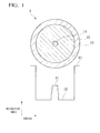
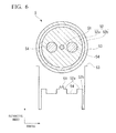
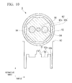
- the refractive index profile may be a known type of profile such as a step index profile such as shown in FIG. 12 , or a graded core profile, an O-ring profile, a dual-core shape profile, a segmented-core profile, a double O-ring profile, or a W profile such as those shown in FIG. 1 and FIGS. 3 through 10.
- the refractive indexes of the core and cladding are preferably adjusted taking consideration given to the structure of the Yb-doped optical fiber or to the desired refractive index difference and the like into account.
- the refractive index of the core in order to confine guided light, it is preferable for the refractive index of the core to be higher than the refractive index of the cladding.
- the refractive index of the cladding on the inner side in a radial direction it is preferable for the refractive index of the cladding on the inner side in a radial direction to be higher than the refractive index of the cladding on the outer side in a radial direction.
- the terms “inner side in a radial direction” and “outer side in a radial direction” refer to a relative positional relationship in the radial direction of a two-layer cladding. Accordingly, the terms “inner side of the cladding in a radial direction” and “outer side of the cladding in a radial direction” refer not just to the two-layer cladding of a double-cladding fiber, but may also refer to any two layers of cladding in a multi-cladding fiber which is provided with three or more layers of cladding.
- nc1 of a cladding on the innermost side in a radial direction a refractive index nc3 of a cladding on the outermost side in a radial direction, and a refractive index nc2 of an intermediate cladding between the claddings on the innermost side and the outermost side to satisfy a relationship of nc1 > nc2 > nc3.
- intermediate cladding refers to any cladding layer located between the cladding layers on the innermost and outermost sides, and does not refer solely, for example, to the intermediate cladding between the cladding layers on the innermost side and outermost side of a triple-cladding fiber.
- the relative refractive index difference between the core and cladding is preferably between 0.05 and 0.65%, and more preferably between 0.05 and 0.25%.
- the term "relative refractive index difference between the core and cladding” refers to a value calculated using the formula (n 1 - no) / n 1 ⁇ 100 (%) when the refractive index of the core is set to be n 1 and the refractive index of the cladding is set to be no.
- the core diameter is preferably appropriately set in accordance with the refractive index of the core. Normally, it is preferably set to between 3 and 50 ⁇ m, and more preferably to between 4 and 43 ⁇ m.
- the Yb-doped optical fiber of the present invention can be manufactured using a conventional manufacturing method.
- the Yb-doped optical fiber of the present invention can be manufactured by preparing a fiber preform using MCVD method or VAD method, and by then drawing this until it has the desired outer diameter. A protective coating layer is then formed on the outer circumference thereof using UV cured resin or the like.
- the Yb can be doped in the fiber preform preparation process using a method such as doping into soot by solution method, or spraying method.
- the outside of the fiber preform can be ground to the desired shape after it has been doped with the Yb, and it can then be drawn.
- a stress induced portion is provided in the cladding
- a hole is formed in the Yb-doped fiber preform in the longitudinal direction thereof.
- a stress induced portion formed from B 2 O 3 - SiO 2 glass which has been prepared using MCVD method or the like is inserted into the hole, and the resulting fiber is then drawn.
- the fiber laser and fiber amplifier of the present invention are characterized in that they have the above described Yb-doped optical fiber of the present invention as an optical amplifying medium. Moreover, except for the fact that the above described Yb-doped optical fiber of the present invention is used as the optical amplifying medium, the fiber laser and fiber amplifier of the present invention can be manufactured using the same methods as those used to manufacture conventional fiber lasers and fiber amplifiers.
- the present invention it is possible using a conventional method such as MCVD method or VAD method to manufacture an Yb-doped optical fiber in which the desired high output light can be obtained and which exhibits a superior photodarkening suppression effect. Moreover, there are no limits on the size of the fiber preform which is used to manufacture this optical fiber. Accordingly, it is possible to provide an Yb-doped optical fiber having the above described superior properties at low cost and in large quantities. Moreover, by using the above described type of optical fiber as an optical amplifying medium, any decrease in output power over time is suppressed, and it is possible to provide a fiber laser and fiber amplifier having excellent optical properties at low cost.
- the present invention will be described in more detail using specific examples. It should be noted, however, that the present invention is in no way limited to these examples.
- the loss increase which is caused by photodarkening in an Yb-doped optical fiber is evaluated using the method described below. As a result of this, it is possible to relatively compare loss increase in optical fibers having mutually between the fibers with different applications and structures.
- FIG. 1 shows a refractive index profile and a cross section in the radial direction of an Yb-doped optical fiber 1.
- the Yb-doped optical fiber 1 is a single cladding fiber.
- Cladding 12 is provided on an outer circumference of a core 11, and a protective coating layer 13 is provided on an outer circumference of the cladding 12.
- a fiber preform was prepared using MCVD method. The then Yb is doped using solution method. The fiber preform was then drawn until the outer diameter of the glass was approximately 125 um, and a protective coating layer was then provided on the outer circumference thereof.
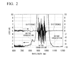
- FIG. 2 A graph showing a relationship between the loss before and after the irradiation of pumping light at the time, and the wavelength dependence of the loss increase (the loss deference between before and after the irradiation of pumping light) is shown in FIG. 2 .
- the reason why noise can be seen in the loss data around the 1000 nm wavelength is because an absorption band of Yb exists in this wavelength band.
- a fiber amplifier was produced and its changes in optical output power over time were evaluated. As a result, it was found that in a fiber amplifier having an initial output power of 1.5 W, the decrease in output power after a time lapse of 100 hours is 3% or less.
- This in output power includes loss caused by factors such as changes in temperature and measurement uncertainty in addition to loss increase in the optical fiber. As a result, it was considered that the decrease in output power caused by loss increase from photodarkening was 1% or less.
- the obtained Yb-doped optical fiber and the evaluation results for this fiber are shown in Table 1.
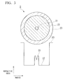
- FIG. 3 shows a refractive index profile and a cross section in the radial direction of an Yb-doped optical fiber 2.
- the Yb-doped optical fiber 2 is a single cladding fiber.
- Cladding 22 is provided on an outer circumference of a core 21, and a protective coating layer 23 is provided on an outer circumference of the cladding 22.
- a fiber preform was prepared using VAD method.
- the Yb is doped using solution method.
- the fiber preform was then drawn until the outer diameter of the glass was approximately 125 ⁇ m, and a protective coating layer was then provided on the outer circumference thereof.
- 0.84 mol% of Al 2 O 3 was contained in the core.
- 0.15 mol% of Yb 2 O 3 and 3.85 mol% of P 2 O 5 were also contained in the core.
- the diameter of the core was approximately 7 ⁇ m, and the relative refractive index difference ( ⁇ ) of the core was approximately 0.25%.
- the loss increase measured using the aforementioned evaluation method was 0.01 dB or less.
- a fiber laser was produced and its changes in optical output power over time were evaluated.
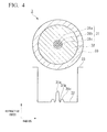
- FIG. 4 shows a refractive index profile and a cross section in the radial direction of an Yb-doped optical fiber 3.
- the Yb-doped optical fiber 3 is a single cladding fiber having a core 31 which has a three-layer structure. Cladding 32 is provided on an outer circumference of the core 31, and a protective coating layer 33 is provided on an outer circumference of the cladding 32.
- the core 31 consists of center core 31a, a ring groove 31b which is provided on an outer circumference of the center core 31a, and a ring core 31 c which is provided on an outer circumference of the ring groove 31 b.
- a fiber preform was prepared using MCVD method.
- the Yb is doped using solution method.
- the fiber preform was then drawn until the outer diameter of the glass was approximately 125 ⁇ m, and a protective coating layer was then provided on the outer circumference thereof.
- 0.80 mol% of Al 2 O 3 was contained in the core.
- 0.17 mol% of Yb 2 O 3 and 3.53 mol% of P 2 O 5 were also contained in the core.
- the diameter of the core was approximately 10.3 ⁇ m, and the relative refractive index difference ( ⁇ ) of the core was approximately 0.15%.
- FIG. 5 shows a refractive index profile and a cross section in the radial direction of an Yb-doped optical fiber 4.
- the Yb-doped optical fiber 4 is a double cladding fiber having cladding 42 which has a two-layer structure.
- Inner side cladding 42a is provided on an outer circumference of a core 41
- outer side cladding 42b is provided on an outer circumference of the inner side cladding 42a
- a protective coating layer 43 is provided on an outer circumference of the outer side cladding 42b.
- the inner side cladding 42a is formed having a D-shaped cross-sectional configuration.
- a fiber preform was prepared using MCVD method.
- the Yb is doped using spraying method in a soot preparation.
- the outside of the circular cylindrical-shaped fiber preform was ground such that the cross-sectional configuration thereof was changed into a D-shaped configuration such as shown in FIG. 5 .
- the obtained fiber preform was then drawn until the diameter of a circumscribed circle of the cross section of the glass was approximately 250 ⁇ m.
- a polymer cladding material having a lower refractive index than that of the glass was coated onto the outer circumference of the glass and then cured so as to form a structure in which pumping light was confined in the glass cladding.
- the outer circumference thereof was coated with a protective UV cured resin.
- 0.92 mol% of Al 2 O 3 was contained in the core.
- 0.19 mol% of Yb 2 O 3 and 2.09 mol% of P 2 O 5 were also contained in the core.
- the diameter of the core was approximately 18.7 ⁇ m, and the relative refractive index difference ( ⁇ ) of the core was approximately 0.10%.
- a cladding NA which was obtained from a refractive index difference between the glass cladding guiding the pumping light and the polymer cladding confining the light was approximately 0.41.
- the loss increase measured using the aforementioned evaluation method was 0.01 dB or less.
- FIG. 6 shows a refractive index profile and a cross section in the radial direction of an Yb-doped optical fiber 5.
- the Yb-doped optical fiber 5 is a double cladding fiber having cladding 52 which has a two-layer structure.
- Inner side cladding 52a is provided on an outer circumference of a core 51
- outer side cladding 52b is provided on an outer circumference of the inner side cladding 52a
- a protective coating layer 53 is provided on an outer circumference of the outer side cladding 52b.
- a pair of stress induced portions 54 and 54 is provided in the inner side cladding 52a at symmetrical positions relative to the core 51.
- a fiber preform was prepared using VAD method.
- the Yb is then doped using spraying method in a soot preparation.
- a pair of holes is formed so as to be positioned symmetrically relative to the core in the longitudinal direction of the fiber preform. Stress induced glass manufactured by adding boron or the like was inserted into these holes.
- the fiber preform was then drawn until the outer diameter of the glass was approximately 125 ⁇ m.
- a polymer cladding material having a lower refractive index than that of the glass was coated onto the outer circumference of the glass and then cured so as to form a structure in which pumping light was confined in the glass cladding.
- the outer circumference thereof was coated with a protective UV cured resin.
- a polarization-maintaining optical fiber was obtained containing 5.32 mol% of Al 2 O 3 , 0.33 mol% of Yb 2 O 3 and 6.86 mol% of P 2 O 5 in the core.
- the diameter of the core was approximately 10.3 ⁇ m, and the relative refractive index difference ( ⁇ ) of the core was approximately 0.15%.
- a cladding NA which was obtained from a refractive index difference between the glass cladding guiding the pumping light and the polymer cladding confining the light was approximately 0.46.
- the loss increase measured using the aforementioned evaluation method was 0.01 dB or less.
- FIG. 7 shows a refractive index profile and a cross section in the radial direction of an Yb-doped optical fiber 6.
- the Yb-doped optical fiber 6 is a double cladding fiber having cladding 62 which has a two-layer structure.
- Inner side cladding 62a is provided on an outer circumference of a core 61
- outer side cladding 62b is provided on an outer circumference of the inner side cladding 62a
- a protective coating layer 63 is provided on an outer circumference of the outer side cladding 62b.
- the inner side cladding 62a has a substantially octagonal-shaped cross-sectional configuration, and the core 61, the inner side cladding 62a, and the outer side cladding 62b are provided concentrically.
- a fiber preform was prepared using VAD method.
- the Yb is doped using solution method.
- the outside of the circular cylindrical-shaped fiber preform was ground such that the cross-sectional configuration thereof was changed into an octagonal-shaped configuration such as that shown in FIG. 7 .
- the obtained fiber preform was then drawn until the diameter of a circumscribed circle of the cross section of the glass was approximately 400 ⁇ m.
- a polymer cladding material having a lower refractive index than that of the glass was coated onto the outer circumference of the glass and then cured so as to form a structure in which pumping light was confined in the glass cladding.
- the outer circumference thereof was coated with a protective UV cured resin.
- FIG. 8 shows a refractive index profile and a cross section in the radial direction of an Yb-doped optical fiber 7.
- the Yb-doped optical fiber 7 is a triple cladding fiber having cladding 72 which has a three-layer structure.
- Innermost cladding 72a is provided on an outer circumference of a core 71
- intermediate cladding 72b is provided on an outer circumference of the innermost cladding 72a
- outermost cladding 72c is provided on an outer circumference of the intermediate cladding 72b
- a protective coating layer 73 is provided on an outer circumference of the outermost cladding 72c.
- the intermediate cladding 72b has a substantially heptagonal-shaped cross-sectional configuration, and the core 71, the innermost cladding 72a, the intermediate cladding 72b, and the outermost cladding 72c are provided concentrically.
- a fiber preform was prepared using MCVD method.
- the Yb is doped using solution method.
- the outside of the circular cylindrical-shaped fiber preform was grinded such that the cross-sectional configuration thereof was changed into a heptagonal-shaped configuration such as that shown in FIG. 8 .
- the obtained fiber preform was then drawn until the diameter of a circumscribed circle of the cross section of the glass was approximately 380 ⁇ m.
- a polymer cladding material having a lower refractive index than that of the glass was coated onto the outer circumference of the glass and then cured so as to form a structure in which pumping light was confined in the glass cladding.
- the outer circumference thereof was coated with a protective UV cured resin.
- a fiber laser was produced and its changes in optical output power over time were evaluated.
- a decrease in output power after a time lapse of 100 hours is 3% or less.
- This decrease in output power includes loss caused by factors such as changes in temperature and measurement uncertainty in addition to loss increase in the optical fiber.
- the decrease in output power caused by loss increase from photodarkening was 1% or less.
- the obtained Yb-doped optical fiber and the evaluation results for this fiber are shown in Table 2.
- FIG. 9 shows a refractive index profile and a cross section in the radial direction of an Yb-doped optical fiber 8.
- the Yb-doped optical fiber 8 is a triple cladding fiber having a core 81 which has a two-layer structure and cladding 82 which has a three-layer structure.
- a ring groove 81b is provided on an outer circumference of a center core 81 a
- innermost cladding 82a is provided on an outer circumference of the ring groove 81b
- intermediate cladding 82b is provided on an outer circumference of the innermost cladding 82a
- outermost cladding 82c is provided on an outer circumference of the intermediate cladding 82b
- a protective coating layer 83 is provided on an outer circumference of the outermost cladding 82c.
- the intermediate cladding 82b has a substantially heptagonal-shaped cross-sectional configuration, and the center core 81 a, the ring groove 81b, the innermost cladding 82a, the intermediate cladding 82b, and the outermost cladding 82c are provided concentrically.
- a fiber preform was prepared using MCVD method.
- the Yb is doped using solution method.
- the outside of the circular column-shaped fiber preform was ground such that the cross-sectional configuration thereof was changed into a heptahedral-shaped configuration such as that shown in FIG. 9 .
- the obtained fiber preform was then drawn until the diameter of a circumscribed circle of the cross section of the glass was approximately 420 ⁇ m.
- a polymer cladding material having a lower refractive index than that of the glass was coated onto the outer circumference of the glass and then cured so as to form a structure in which pumping light was confined in the glass cladding.
- the outer circumference thereof was coated with a protective UV cured resin.
- a fiber laser was produced and its changes in optical output power over time were evaluated.
- a decrease in output power after a time lapse of 100 hours is 3% or less.
- This decrease in output power included loss caused by factors such as changes in temperature and measurement uncertainty in addition to loss increase in the optical fiber. Because of this, it was considered that the decrease in output power caused by loss increase from photodarkening was 1% or less.
- the obtained Yb-doped optical fiber and the evaluation results for this fiber are shown in Table 2.
- FIG. 10 shows a refractive index profile and a cross section in the radial direction of an Yb-doped optical fiber 9.
- the Yb-doped optical fiber 9 is a double cladding fiber having cladding 92 which has a two-layer structure.
- Inner side cladding 92a is provided on an outer circumference of a core 91
- outer side cladding 92b is provided on an outer circumference of the inner side cladding 92a
- a protective coating layer 93 is provided on an outer circumference of the outer side cladding 92b.
- a pair of stress induced portions 94 and 94 is provided in the inner side cladding 92a at symmetrical positions relative to the core 91.
- the inner side cladding 92a has a substantially octahedral-shaped cross-sectional configuration, and the core 91, the inner side cladding 92a, and the outer side cladding 92b are provided concentrically.
- the core was also doped with Ge and F.
- a fiber preform was prepared using MCVD method. The Yb is doped using solution method. At this point, the outside of the circular column-shaped fiber preform was ground such that the cross-sectional configuration thereof was changed into an octahedral-shaped configuration such as that shown in FIG. 10 .
- a pair of holes is then formed so as to be positioned symmetrically relative to the core in the direction of the center axis of the fiber preform. Stress induced glass manufactured by adding boron or the like was then inserted into these holes. The obtained fiber preform was then drawn until the diameter of a circumscribed circle of the cross section of the glass was approximately 250 ⁇ m.
- a polymer cladding material having a lower refractive index than that of the glass was coated onto the outer circumference of the glass and then cured so as to form a structure in which pumping light was confined in the glass cladding.
- the outer circumference thereof was coated with a protective UV cured resin.
- polarization-maintaining optical fiber was obtained having 1.72 mol% of Al 2 O 3 , 0.26 mol% of Yb 2 O 3 , 2.35 mol% of P 2 O 5 , 0.83 mol% of GeO 2 , and 0.35 mol% of F contained in the core.
- the diameter of the core was approximately 9.3 ⁇ m, and the relative refractive index difference ( ⁇ ) of the core was approximately 0.22%.
- a cladding NA which was obtained from a refractive index difference between the glass cladding guiding the pumping light and the polymer cladding confining the light was approximately 0.46. There was substantially no sign of any loss increase which was caused by photodarkening in the obtained Yb-doped optical fiber.
- the loss increase measured using the aforementioned evaluation method was 0.01 dB or less.
- a fiber laser was produced and its changes in optical output power over time were evaluated.
- This decrease in output power included loss caused by factors such as changes in temperature and measurement uncertainty in addition to loss increase in the optical fiber. Because of this, it was considered that there was substantially no decrease in output power caused by loss increase from photodarkening.
- a grating structure was formed by excimer laser exposure in the obtained Yb-doped optical fiber.
- the Yb-doped optical fibers shown in Tables 2 to 5 were prepared using the same procedure as that in Examples 1 to 9, and the loss increases caused by photodarkening were evaluated.
- the configurations (shape) of the core and cladding of a cross section in the radial direction of the respective Yb-doped optical fibers were as is described below.
- Example 11; cross-sectional configuration is the same as in FIG. 6 .
- Example 12; cross-sectional configuration is the same as in FIG. 1 .
- Example 13; cross-sectional configuration is the same as in FIG. 5 .
- Example 14; cross-sectional configuration is the same as in FIG. 6 .
- Example 25 cross-sectional configuration is the same as in FIG. 5 .
- Example 26 cross-sectional configuration is the same as in FIG. 1 .
- Comparative example 1; cross-sectional configuration is the same as in FIG. 1 .
- Comparative example 2; cross-sectional configuration is the same as in FIG. 1 .
- the Yb-doped optical fiber of Comparative example 1 contains Ge in the core but does not contain P therein. Excepting this, it is the same as in the Examples. For example, it has substantially the same initial optical amplification properties as the Yb-doped optical fibers of the Examples in which the refractive index and Yb concentration and the like are substantially equal.
- a relationship between the loss before and after the irradiation of pumping light and the wavelength dependence of loss increase in Comparative example 1 is shown as a graph in FIG. 11 . From FIG. 11 it was possible to confirm that there was a loss increase which was a monotonically increase to the short wavelength side after the pumping light irradiation. In FIG. 11 , the reason why noise can be seen in the loss data around the 1000 nm wavelength is the same as in FIG. 2 , namely, because an Yb absorption band exists in this wavelength band.
- the Yb-doped optical fiber of Comparative example 2 has a P 2 O 5 equivalent concentration in the core which is lower than the Al 2 O 3 equivalent concentration therein. Excepting this, it is the same as in the Examples. In addition, as is clear from Table 5, it was conformed that the Yb-doped optical fiber of Comparative example 2 did not exhibit sufficient loss increase suppression.
- Example 1 Example 2 Example 3 Example 4 Example 5 Example 6 Al 2 O 3 concentration (mol%) 1.67 0.84 0.80 0.92 5.32 0.78 Yb 2 O 3 concentration (mol%) 0.54 0.15 0.17 0.19 0.33 0.14 P 2 O 5 concentration (mol%) 8.37 3.80 3.35 2.09 6.86 1.85 P 2 O 5 concentration/ Al 2 O 3 concentration 5.01 4.32 4.41 2.27 1.29 2.37 P 2 O 5 concentntion/(Yb 2 O 3 concentration + 3.79 3.84 3.64 1.88 1.21 2.01 Yb 2 O 3 concentration/ Al 2 O 3 concentration 0.32 0.18 0.21 0.21 0.06 0.18 Other content elements (concentration, mol%) - - - - - - - - Relative refractive index difference of core (%) 0.64 0.25 0.15 0.10 0.15 0.09 Core diameter ( ⁇ m) 4.9 7.0 10.3 18.7 10.3 35 Cladding structure Single Single Single Double Double Double Double Glass cladding (circumscribed circle) diameter ( ⁇ m) 125 125 125 250 125 400 Photo
- Example 7 Example 8
- Example 9 Example 10
- Example 11 Example 12 Al 2 O 3 concentration (mol%) 10.49 11.03 1.72 0.23 11.82 4.25 Yb 2 O 3 concentration (mol%) 0.36 0.71 0.26 0.15 0.72 0.51 P 2 O 5 concentration (mol%) 14.96 14.43 2.35 2.46 13.82 5.02 P 2 O 5 P 2 O 5 concentration/ Al 2 O 3 concentration 1.43 1.31 1.37 10.70 1.17 1.18 P 2 O 5 concentration/(Yb 2 O 3 concentration - Al 2 O 3 concentration) 1.38 1.23 1.19 6.47 1.10 1.05 Yb 2 O 3 concentration/ Al 2 O 3 concentration 0.03 0.06 0.15 0.65 0.06 0.12
- Other content elements Concentration mol%) - - GeO 2 (0.83) F (0.35) - - - Relative refractive index difference of core (%) 0.11 0.10 0.22 0.20 0.43 0.27 Core diameter ( ⁇ m) 24 34 9.3 9.6 6.5 8.8 Cladding structure Triple Triple Double Double Double Double Double Double Double Double Double Double Double Double Double Double Double Double
- Example 13 Example 14
- Example 15 Example 16
- Example 18 Al 2 O 3 concentration (mol%) 9.81 0.34 0.43 10.26 10.91 4.79 Yb 2 O 3 concentration (mol%) 0.11 0.68 0.01 0.99 0.22 0.35 P 2 O 5 concentration (mol%) 14.82 6.32 4.83 13.21 19.83 4.89 P 2 O 5 concentration/ Al 2 O 3 concentration 1.51 18.59 11.23 1.29 1.82 1.02 P 2 O 5 concentration/(Yb 2 O 3 concentration - Al 2 O 3 concentration) 1.49 6.20 10.98 1.17 1.78 0.95 Yb 2 O 3 concentration/ Al 2 O 3 concentration 0.01 2.00 0.02 0.10 0.02 0.07
- Other content elements Concentration, mol%) - - - - - - - - - Relative refractive index difference of core (%) 0.35 0.69 0.27 0.22 0.61 0.15 Core diameter ( ⁇ m) 6.8 4.7 8.7 15.8 4.9 13.8
- Cladding structure Double Double Double Double Double Double Double Double Double Double Double Double Double Double Double Double Double Double Double Double Double
- Example 19 Example 20 Example 21 Example 22 Example 23 Example 24 Al 2 O 3 concentration (mol%) 2.38 1.81 1.67 0.84 1.62 3.81 Yb 2 O 3 concentration (mol%) 0.63 0.09 0.54 0.15 0.35 0.25 P 2 O 5 concentration (mol%) 4.96 2.63 8.37 3.82 2.21 5.53 P 2 O 5 concentration Al 2 O 3 concentration 2.08 1.45 5.01 4.55 1.36 1.451 P 2 O 5 concentration/(Yb 2 O 3 concentration + Al 2 O 3 concentration) 1.65 1.38 3.79 3.86 1.12 1.362 Yb 2 O 3 concentration/ Al 2 O 3 concentration 0.26 0.05 0.32 0.18 0.22 0.066 Other content elements (concentration mol%) - - - - GeO 2 (0.83) F (0.45) Relative refractive index difference of core (%) 0.13 0.05 0.65 0.25 0.29 0.11 Core diameter ( ⁇ m) 30 40 4.7 9.2 7.2 24 Cladding structure Triple Double Single Double Double Double Double Double Glass cladding (circumscribed circle)diameter ( ⁇ m) 400 400
- the present invention can be used as a high output light source laser medium for material processing applications such as welding, marking, cutting and the like.
Landscapes
- Physics & Mathematics (AREA)
- Optics & Photonics (AREA)
- Electromagnetism (AREA)
- Chemical & Material Sciences (AREA)
- Engineering & Computer Science (AREA)
- General Chemical & Material Sciences (AREA)
- Chemical Kinetics & Catalysis (AREA)
- Geochemistry & Mineralogy (AREA)
- Materials Engineering (AREA)
- Organic Chemistry (AREA)
- Life Sciences & Earth Sciences (AREA)
- Plasma & Fusion (AREA)
- General Physics & Mathematics (AREA)
- Lasers (AREA)
Abstract
Description
- The present invention relates to an ytterbium-doped optical fiber in which photodarkening has been suppressed, and to a fiber laser and a fiber amplifier which are provided with this optical fiber.
Priority is claimed on Japanese Patent Application No.2008-201171, filed August 04, 2008 PCT/JP2009/052906, filed February 19, 2009 - An amplifying optical fiber having an axially symmetric waveguide structure in which a core and/or a cladding has been doped with rare earth elements are used as optically-active media of fiber amplifiers and fiber lasers. In particular, Yb-doped optical fibers which contain ytterbium (Yb) as the rare earth element can obtain high-power output light with excellent beam quality. The oscillation wavelength of this output light is the wavelength around 1 µm which is substantially the same as ND-YAG laser which is a conventional type of existing high output laser. Because of this, practical applications of Yb-doped fiber lasers as a high output light source laser medium are expected to be material processing such as welding, marking, cutting and the like.
-
FIG. 12 shows an example of a cross section in the radial direction of a conventional Yb-doped optical fiber and of the refractive index profile thereof.
An Yb-dopedoptical fiber 110 shown here is a single cladding fiber in which cladding 112 is provided on an outer circumference of acore 111, and aprotective coating layer 113 is provided on an outer circumference of thecladding 112. In this Yb-dopedoptical fiber 110, the refractive index of thecore 111 is higher than the refractive index of thecladding 112, in order for guided lights to be confined. Normally, a refractive index-raising dopant such as germanium (Ge), aluminum (Al), or phosphorus (P) is doped into thecore 111, in order to raise the refractive index of thecore 111. Furthermore, thecore 111 is also doped with a dopant Yb which has an optical amplifying function. Yb is normally doped into thecore 111 so as to have a substantially uniform density distribution. However, it is acceptable if there is some density distribution and it is also possible for a portion of thecladding 112 to be doped.
A high-power signal light can be obtained by making pumping light incident on this Yb-doped optical fiber and then making signal light incident thereon, or by making pumping light incident on this Yb-doped optical fiber and then consisting cavities using a fiber Bragg grating. - Normally, when an Yb-doped optical fiber is used as an optical amplifying medium in a fiber laser or fiber amplifier, the Yb-doped optical fiber is mostly used in an effectively single-mode condition in order to utilize the advantages of a fiber-type optical amplifying medium, namely, the ability to realize restricted propagating condition together with excellent cooling efficiency to be utilized.
The conditions of an optical waveguide which enable effectively single-mode propagation to be achieved are determined by conditions of the refractive index of the core and the core diameter (namely, refractive index profile in the radial direction of the core) and the winding diameter of the fiber and the like. At this time, it is necessary either the core have a low refractive index or the core diameter is small.
In contrast, in view of the properties of an optical amplifying medium, it is desirable for it to be possible to output even higher-power light. Namely, making it possible for high-power light to be propagated through an optical fiber is a requirement for a better amplifying optical fiber. However, in the case when a same light power is incident into an optical fiber having a small core diameter, then compared with the case when such light is incident into an optical fiber having a large core diameter, because the light-propagating cross-sectional area (i.e., the mode field diameter) in the former case is smaller than that in the latter case, the power density of the light being propagated through the core is increased. As a result, damage in the core glass due to the light and non-linear optical phenomena is easily induced. Alternatively, the amplified power during light propagation becomes restricted. Accordingly, for reasons such as these, larger core diameters are desirable. Consequently, in order to enlarge the core diameter and enable single-mode propagation to be realized, it is necessary to lower the core refractive index. - One of the factors which cause the properties of a fiber amplifier or fiber laser to deteriorate is loss increase (i.e., photodarkening) of an optical fiber which is caused by the pumping light or signal light propagated through the optical fiber (see Non-patent
documents 1 and 2). Because of this loss increase, the optical amplifying efficiency of the rare earth-doped optical fiber serving as the light amplifying medium is gradually decreased. As a result, the output of the fiber amplifier or fiber laser is decreased over time and the product lifetime thereof is accordingly shortened. - Thus, various methods for suppressing photodarkening have been disclosed up to this time.
For example, inNon-patent document 1, a method is disclosed in which photodarkening is suppressed by employing a special manufacturing method known as DND (Direct Nanoparticle Deposition).
Moreover, inNon-patent document 2, a method is disclosed in which photodarkening is suppressed by doping a high concentration of aluminum into an optical fiber during the manufacturing thereof.
Moreover, inPatent document 1. a method is disclosed in which photodarkening is suppressed by doping hydrogen into an optical fiber. -
- [
Patent document 1 Japanese Unexamined Patent Application, First Publication No.2007-114335 -
- [Non-patent document 1] "The Potential of Direct Nanoparticle Deposition for the Next Generation of Optical Fibers" S. Tammela et.al., The Proceedings of SPIE Photonics West 2006, Vol. 6116-16 (2006)
- [Non-patent document 2] "Population Inversion Factor Dependence of Photodarkening of Yb-doped Fibers and Its Suppression by Highly Aluminum Doping" T. Kitabayashi et.al., The Proceedings of OFC 2006, OThC5 (2006)
- However, according to the method described in
Non-patent document 1, although photodarkening is certainly suppressed more than when manufacturing is performed in accordance with the conventional method, the suppression effect is still insufficient. Moreover, because a special manufacturing method is employed, a larger number of hydroxyl (OH) group contaminate into the optical fiber, compared with a conventional method such as MCVD method or VAD method. As a result, an OH loss becomes high. Furthermore, the manufacturing costs of DND method also increase because the size of the fiber preform used for the manufacturing is limited. Consequently, it is not possible to manufacture an amplifying optical fiber in which photodarkening is suppressed at low cost.
In the method described inNon-patent document 2, it is necessary for a large quantity of aluminum to be used, in order to sufficiently suppress photodarkening. As a result of this, the refractive index of the core of the optical fiber becomes high. In this case, it is necessary to make the core diameter smaller in order for the optical fiber to be operated in single-mode. However, as is described above, the desired output power cannot be obtained.
According to the method described inPatent document 1, although photodarkening is able to be suppressed, it is necessary to perform a hydrogen immersing process and a light irradiation process. Accordingly, the manufacturing process is more complex, and it is difficult to manufacture optical fibers in a large quantity. - The present invention was conceived in view of the above described circumstances, and it is an object thereof to provide an optical fiber in which photodarkening is suppressed and which can be manufactured using a conventional method.
- The present invention employs the followings in order to solve the above described problems and achieve the desired objectives.
- (1) An ytterbium-doped optical fiber of the present invention includes: a core which contains at least ytterbium, aluminum, and phosphorus; and a cladding which encircles the core, wherein an aluminum oxide equivalent concentration of the aluminum in the core is 0.2 mol% or more; a diphosphorus pentaoxide equivalent concentration of the phosphorus is higher than the equivalent concentration of the aluminum oxide.
- (2) It is preferable for the core to either not contain germanium or to contain less than 1.1 mol% of germanium in a germanium dioxide equivalent concentration.
- (3) It is preferable for the diphosphorus pentaoxide equivalent concentration in the core to be greater than a summation of an ytterbium oxide equivalent concentration of the ytterbium and the aluminum oxide equivalent concentration in the core.
- (4) It is preferable for a ratio between an ytterbium oxide equivalent concentration and the aluminum oxide equivalent concentration in the core to be in a range of 0.01 to 2.
- (5) It is preferable for the ytterbium oxide equivalent concentration in the core to be in a range of 0.01 to 1.0 mol%.
- (6) It is preferable for the diphosphorus pentaoxide equivalent concentration in the core to be 20 mol% or less.
- (7) It is preferable for the diphosphorus pentaoxide equivalent concentration to be not more than twice the aluminum oxide equivalent concentration in the core.
- (8) It is preferable for a relative refractive index difference between the core and the cladding to be in a range of 0.05 to 0.65%.
- (9) It is more preferable for a relative refractive index difference between the core and the cladding to be in a range of 0.05 to 0.25%.
- (10) It is preferable for the core to further contain at least one of fluorine and boron.
- (11) It is preferable for the core to further contain at least one element selected from a group consists of transition metal elements and rare earth elements other than ytterbium.
- (12) It is preferable for at least two layers of cladding to be provided, and for a refractive index of the cladding on an inner side in a radial direction to be higher than a refractive index of the cladding on an outer side in the radial direction.
- (13) In the case of (12), it is preferable for at least three layers of cladding to be provided, and for a refractive index nc1 of the cladding on an innermost side in the radial direction, a refractive index nc3 of the cladding on an outermost side in the radial direction, and a refractive index nc2 of an intermediate cladding between the innermost cladding and the outermost cladding to satisfy a relationship of
nc 1 > nc2 > nc3. - (14) A fiber laser of the present invention includes the ytterbium-doped optical fiber according to (1) as an optical amplifying medium.
- (15) A fiber amplifier of the present invention includes the ytterbium-doped optical fiber according to (1) as an optical amplifying medium.
- In the ytterbium-doped optical fiber according to the above described (1), the aluminum oxide equivalent concentration of the aluminum in the core is 0.2 mol% or more, and a diphosphorus pentaoxide equivalent concentration of the phosphorus is higher than the aluminum oxide equivalent concentration. Because of this, crystallization of the glass is prevented and photodarkening is also suppressed. As a result, it is possible to provide optical fibers at low cost and in large quantities from which a superior optical amplifying effect can be obtained. Moreover, it is possible to provide a fiber laser and fiber amplifier at low cost which have superior optical characteristics and any decrease in output power thereof over time is suppressed, by using this type of optical fiber as an optical amplifying medium.
-
-
FIG. 1 is a view showing a cross section in the radial direction and a refractive index profile of an Yb-doped optical fiber manufactured according to Example 1 of the present invention. -
FIG 2 is a graph showing a relationship between loss before and after an irradiation of pumping light and a wavelength dependence of a loss increase after the irradiation thereof in Example 1 of the present invention. -
FIG. 3 is a graph showing a relationship between loss before and after an irradiation of pumping light and a wavelength dependence of a loss increase after the irradiation thereof in Example 2 of the present invention. -
FIG. 4 is a graph showing a relationship between loss before and after an irradiation of pumping light and a wavelength dependence of a loss increase after the irradiation thereof in Example 3 of the present invention. -
FIG. 5 is a graph showing a relationship between loss before and after an irradiation of pumping light and a wavelength dependence of a loss increase after the irradiation thereof in Example 4 of the present invention. -
FIG. 6 is a graph showing a relationship between loss before and after an irradiation of pumping light and a wavelength dependence of a loss increase after the irradiation thereof in Example 5 of the present invention. -
FIG. 7 is a graph showing a relationship between loss before and after an irradiation of pumping light and a wavelength dependence of a loss increase after the irradiation thereof in Example 6 of the present invention. -
FIG. 8 is a graph showing a relationship between loss before and after an irradiation of pumping light and a wavelength dependence of a loss increase after the irradiation thereof in Example 7 of the present invention. -
FIG. 9 is a graph showing a relationship between loss before and after an irradiation of pumping light and a wavelength dependence of a loss increase after the irradiation thereof in Example 8 of the present invention. -
FIG. 10 is a graph showing a relationship between loss before and after an irradiation of pumping light and a wavelength dependence of a loss increase after the irradiation thereof in Example 9 of the present invention. -
FIG. 11 is a graph showing a relationship between loss before and after an irradiation of pumping light and a wavelength dependence of a loss increase after the irradiation thereof in Comparative example 1. -
FIG. 12 is a view showing an example of a cross section in the radial direction of a conventional Yb-doped optical fiber and of the refractive index profile thereof. - The present invention will now be described in detail.
In the description given below, the concentration of doped components which is shown in units of "mol%" is an averaged value in the core in an optical fiber having a refractive index profile, unless specifically stated otherwise.
The term "core diameter" refers to a diameter having a relative refractive index difference of 1/e of the maximum relative refractive index difference of the core. - The Yb-doped optical fiber of the present invention includes a core and cladding that surrounds this core. The core contains at least Yb, Al, and P. The equivalent concentration of aluminum oxide (Al2O3) of the aluminum in the core is 0.2 mol% or more, and the equivalent concentration of diphosphorus pentaoxide (P2O5) of the phosphorus in the core is higher than the equivalent concentration of the Al2O3.
P is a dopant which has a photodarkening suppression effect and a refractive index raising effect.
Al is a dopant which has a refractive index raising effect and a glass crystallization prevention effect (suppression effect).
Yb is a dopant which has a light amplifying effect. - The P in the core has a photodarkening suppression effect. However, in an optical fiber whose core only contains Yb and P, the glass becomes crystallized when the core refractive index is set to be the desired low value. Because of this, such optical fibers cannot be used as amplifying optical fibers. However, the crystallization of the glass can be prevented even if the core refractive index is set to be a desired low value while the photodarkening is suppressed, by doping Al in the core. The reason why Al has a glass crystallization prevention effect is thought to be because it causes the Yb and P to be dispersed throughout the glass microscopically.
In the present invention, the P2O5 equivalent concentration of the P (hereinafter, referred to simply as "P2O5 equivalent concentration") and the Al2O3 equivalent concentration of the Al (hereinafter, referred to simply as "Al2O3 equivalent concentration") in a core containing Yb are set within predetermined ranges, respectively. Both a high level of photodarkening suppression and glass crystallization prevention can be achieved, by setting those equivalent concentrations as described above.
Furthermore, in the present invention, an even more excellent light amplifying effect can be obtained without affecting (undermining) the photodarkening suppression effect and the glass crystallization prevention effect, by setting the Ytterbium oxide (Yb2O3) equivalent concentration of the Yb (hereinafter, referred to simply as "Yb2O3 equivalent concentration") to a preferable predetermined range. - Because of the above described reasons, in the present invention, the Al2O3 equivalent concentration in the core is set to be 0.2 mol% or more. Furthermore, the Al2O3 equivalent concentration is preferably set within a range of 0.2 to 12 mol%, and more specifically set within a range of 0.23 to 11.82 mol%. An even greater glass crystallization prevention effect can be obtained by setting the Al2O3 equivalent concentration to 0.2 mol% or more, even if the refractive index of the core is lowered.
In addition, an even greater suppression effect of optical fiber transmission loss can be obtained, by setting the Al2O3 equivalent concentration to 12 mol% or less. This range of 0.2 to 12 mol% of the Al2O3 equivalent concentration corresponds to a range of 0.08 to 4.8 mol% (atomic percent) as a concentration ofAl in the core. - Moreover, in the present invention, the P2O5 equivalent concentration in the core is set to higher than the Al2O3 equivalent concentration. As a result, a greater photodarkening suppression effect can be obtained while glass crystallization is also prevented.
Furthermore, the P2O5 equivalent concentration is preferably not more than 19 times greater than the Al2O3 equivalent concentration, and is more preferably not more than 12 times, and is even more preferably not more than 5.5 times, and is most preferably not more than 2 times greater than the Al2O3 equivalent concentration. An even greater core refractive index rise suppression effect is obtained, by setting the P2O5 equivalent concentration within this range. - Moreover, the P2O5 equivalent concentration is preferably set to be 20 mol% or less, and more preferably set within a range of 0.5 to 20 mol%, and particularly preferably set within a range of 1.5 to 20 mol%, more specifically set within a range of 1.85 and 19.83 mol%. If an optical fiber contains a greater quantity of P than is necessary, then the transmission loss of the optical fiber increases. However, by setting the P2O5 equivalent concentration within the above described range, transmission loss is enough low and an even greater light amplifying effect can be obtained. The range of 1.5 to 20 mol% of the P2O5 equivalent concentration corresponds to a range of 0.43 to 5.7 mol% (atomic percent) as a concentration of P in the core.
- Moreover, the Yb2O3 equivalent concentration in the core is preferably set within a range of 0.01 to 1.0 mol%, and more specifically set within a range of 0.01 to 0.99 mol%. By setting the Yb2O3 equivalent concentration more than 0.01 mol%, a greater light amplifying effect can be obtained. Moreover, by setting the Yb2O3 equivalent concentration less than 1.0 mol%, the Yb can be doped stably as a solid solution in the glass, and not only is photodarkening suppressed, but an excellent light amplifying efficiency can be obtained. Note that the range of 0.01 to 1.0 mol% of Yb2O3 equivalent concentration corresponds to a range of 0.004 to 0.4 mol% (atomic percent) as a concentration of Yb in the core.
- The concentration ratio between the Yb2O3 equivalent concentration and the Al2O3 equivalent concentration (i.e., Yb2O3 equivalent concentration / Al2O3 equivalent concentration) in the core is preferably within a range of 0.01 to 2. By setting this ratio to be 2 or less, an even greater glass crystallization preventing effect of Al is obtained. In contrast, by setting this concentration ratio to be 0.01 or more, even if the Al content is reduced in order to lower the refractive index, even more superior optical characteristics and light amplifying effect can be obtained without content insufficiency of the Yb. Moreover, even if the Yb content is increased in order to obtain a sufficient optical amplifying effect, because the Al content can still be maintained within an appropriate range, the refractive index is not increased to a greater level than is necessary.
- The P2O5 equivalent concentration is preferably larger than the summation of the Yb2O3 equivalent concentration and the Al2O3 equivalent concentration, and is more preferably in the range of 1.05 to 11.5 times this summation. An even greater photodarkening suppression effect is obtained while glass crystallization is prevented, by setting the P2O5 equivalent concentration within this range.
- The core and cladding are preferably formed from silica glass. In addition to silica glass being commonly used for typical transmission optical fiber, it also makes it possible for transmission loss to be reduced and is effective in amplifying a light efficiently.
- It is also possible for other elements to be included in the core in addition to Yb, Al, and P. It is possible to improve the function of an Yb-doped optical fiber or provide it with different functions, by doping other elements in the core.
For example, it is possible to easily form a fiber Bragg grating in an Yb-doped optical fiber by doping Ge in the core.
Moreover, by doping either one of or both of fluorine (abbreviated below to F) and boron (abbreviated below to B) in the core, controlling the refractive index profile of the core becomes easy and it is easy to obtain an optical fiber which has the desired optical characteristics.
Furthermore, by doping at least one type of element selected from a group which consists of transition metal elements and rare earth elements other than ytterbium in the core, it is possible to cause a co-dopant sensitization effect to be exhibited, or to change the pumping wavelength, or to cause oscillation to occur in an another specific wavelength. - The rare earth element may be a known rare earth element which is used in conventional Yb-doped optical fibers, and specific examples thereof include erbium (Er), thulium (Tm), yttrium (Y), holmium (Ho), samarium (Sm), praseodymium (Pr), neodymium (Nd), and the like.
The transition metal element may also be appropriately selected from known elements in accordance with the desired object. - Either one type or two or more types of these other elements may be doped in the core. In addition, these elements may be doped into the core using a known method such as solution method or the like.
- The type of other element that is doped in the core may also be appropriately selected in accordance with the desired object. Moreover, the concentration thereof can be appropriately set in accordance with the type of element.
For example, if Ge is doped in the core, the germanium dioxide (GeO2) equivalent concentration is preferably set in the range of 0.1 to 1.1 mol%, and more preferably set in the range of 0.3 to 0.59 mol%. The 0.1 to 1.1 mol% of the germanium dioxide (GeO2 equivalent concentration corresponds to 0.035 to 0.37 mol% (atomic percent) of a Ge concentration in the core. It is known that there is approximately 0.1% rise in the relative refractive index per 1 mol% of GeO2 Accordingly, in order to obtain a particular desired refractive index from an optical waveguide design, it is necessary to relatively decrease the doped amount of diphosphorus pentaoxide, aluminum oxide, and ytterbium oxide and the like which also have the refractive index raising effect. For example, if 2 mol% of germanium dioxide is doped, there is a 0.2% rise in relative refractive index of the core. Because of this, it is necessary to manufacture an optical fiber with a doped amount of either one or a plurality of diphosphorus pentaoxide, aluminum oxide, and ytterbium oxide, which results in decreasing the relative refractive index by approximately 0.2%. If the doped amount of the diphosphorus pentaoxide is decreased, the photodarkening suppression effect is insufficient, and if the doped amount of the aluminum oxide is decreased, it becomes impossible to manufacture a product because of glass crystallization. Moreover, if the doped amount of the ytterbium oxide is decreased, the amplifying effect is decreased by a corresponding amount, which is undesirable. For example, comparison is made in a case of an ytterbium-doped fiber in which a relative refractive index difference of 0.35% between the core and the cladding is designed, it is necessary to decrease the doped amount of diphosphorus pentaoxide, aluminum oxide, or ytterbium oxide, which results in decreasing of a relative refractive index by 0.2%. For example, if the 0.2% of the relative refractive index is decreased only by the diphosphorus pentaoxide, then it is necessary to decrease the doped amount of the diphosphorus pentaoxide by 4.3 mol%. As a result, the photodarkening suppression effect becomes insufficient. Moreover, if the 0.2% of the relative refractive index is decreased only by the aluminum oxide, then it is necessary to decrease the doped amount of the aluminum oxide by 1.4 mol%. As a result, the glass crystallization occurred, and it becomes impossible for a product to be manufactured. Moreover, because the concentration of the ytterbium oxide is generally small, it is not possible to reduce 0.2% of the relative refractive index only by the reduction of the doped amount of the ytterbium oxide. As can be clearly seen, there are many undesirable results if a large amount of GeO2 is doped in the core. In contrast, if there is a small amount of GeO2, then the object of adding the dopant is not satisfactorily achieved. For example, if a grating is to be formed to the optical fiber, the minimum limit required for the GeO2 concentration is preferably set to be 0.1 mol%, and more preferably set to 0.3 mol% or more. In contrast, in consideration of the negative effects caused by a large amount of GeO2 a maximum limit for the doped amount of GeO2 is preferably set to be approximately 1.1 mol%, and more preferably set to be 0.59 mol% or less. If 0.6 mol% of germanium dioxide is doped, then there is a rise of approximately 0.06% in the relative refractive index of the core. Therefore, it is necessary to manufacture the optical fiber with the doped amount of either one or a plurality of diphosphorus pentaoxide, aluminum oxide, and ytterbium oxide, which results in decreasing of relative refractive index by approximately 0.06%. If the diphosphorus pentaoxide is decreased, the photodarkening suppression effect becomes insufficient, and if the aluminum oxide is decreased, it becomes impossible to manufacture a product because of the glass crystallization. Moreover, if the ytterbium oxide is decreased, it is undesirable because the amplifying effect is decreased by a corresponding amount. For example, a comparison is made in a case of an ytterbium-doped fiber in which a relative refractive index difference of 0.35% between the core and the cladding is designed, it is necessary to decrease the doped amount of diphosphorus pentaoxide, aluminum oxide, or ytterbium oxide, which results in decreasing of a relative refractive index by 0.06%. For example, if the 0.06% of the relative refractive index is decreased only by the diphosphorus pentaoxide, then it is necessary to decrease the doped amount of the diphosphorus pentaoxide by 1.3 mol%. As a result, the photodarkening suppression effect becomes insufficient. Moreover, if the 0.06% of the relative refractive index is decreased only by the aluminum oxide then it is necessary to decrease the doped amount of the aluminum oxide by 0.4 mol%. As a result, the glass crystallization occurred, and it becoming impossible for a product to be manufactured. Moreover, in the case where the 0.06% of the relative refractive index is decreased only by the ytterbium oxide, because the concentration of ytterbium oxide is generally small, a reduction of 0.06% in the relative refractive index only by the reduction of the ytterbium oxide is undesirable from the standpoint of amplifying efficiency.
Moreover, as described above, when there is no special reason for doping GeO2 such as to form a grating or the like, it is desirable that, as far as possible, GeO2 is not doped. The reason for this is that, as is described above, because there is a rise in the refractive index due to the GeO2 being doped irrespective of the fact that the doping of the GeO2 has no specific effect on photodarkening, there is a decreased power resistant in contrast to there being a decrease in the effective cross-sectional area. In the same way, when there is no specific effect by doping another element other than Al or P which raises the refractive index (such as Ti or the like), then it is desirable that, as far as possible, there is no doping of such an element which raises the refractive index (refractive index raising element).
Moreover, in a case when B is doped in the core, the boron oxide (B2O3) equivalent concentration is preferably set within a range of 0.01 to 5 mol%, and more preferably set within a range of 0.05 to 1 mol%. An increase in residual stress is suppressed and an optical fiber with a sufficient strength is obtained, by setting the boron oxide equivalent concentration to less than the upper limit value of this range.
Moreover, in a case when F is doped in the core, then it is preferably doped within a concentration range of 0.05 to 3 mol%, and more preferably within a range of 0.1 to 1 mol%. The costs can be reduced by setting the concentration to less than the upper limit value of this range.
Moreover, in a case when erbium (Er) is doped as a rare earth element or transition metal element in the core, the erbium oxide (Er2O3) equivalent concentration is preferably set within a range of 0.01 to 1 mol%, and more preferably set within a range of 0.05 to 0.5 mol%. Some problems such as concentration quenching and the like can be suppressed, by setting the erbium oxide equivalent concentration to less than the upper limit value of this range. - It is possible for the elements such as Yb and the like in the core to have a distributed concentration in the core. However, in order to obtain superior optical characteristics, it is preferable for the concentration to be substantially uniform.
- The cladding may have a single layer structure or may have a multiple layer structure such as a double layer structure, triple layer structure or the like.
For example, a higher output light (light with higher output power) can be obtained than from a single-cladding fiber by employing a multi-cladding fiber such as a double-cladding fiber, triple-cladding fiber or the like. In the multi-cladding fiber, it is possible to suppress power density of the pumping light in the core by guiding pumping light to the cladding. As a result, it is possible to suppress any damage to the core glass and to suppress non-linear optical phenomena due to the pumping light, and to manufacture a fiber laser or fiber amplifier having an even greater output power. In view of this, a triple-cladding fiber which has a high level of utilization efficiency of pumping light is preferable than a double-clad fiber.
Moreover, the shape of the cladding is not particularly limited and may be appropriately selected in accordance with the desired object. For example, as is shown inFIG. 5 andFIGS. 7 through 10 , in order to suppress skew modes, it is preferable for the cross-sectional shape of the cladding in a radial direction to be a non-circular shape such as a polygonal shape and a D-shape or the like.
Moreover, it is also possible for stress induced portions (stress applying portion) to be provided in the vicinity of the core. The stress induced portions may be formed, for example, from a material obtained by doping B2O3 or the like into silica glass. - The refractive index profile of a core may be appropriately adjusted in accordance with the desired object. For example, the refractive index profile may be a known type of profile such as a step index profile such as shown in
FIG. 12 , or a graded core profile, an O-ring profile, a dual-core shape profile, a segmented-core profile, a double O-ring profile, or a W profile such as those shown inFIG. 1 andFIGS. 3 through 10. - The refractive indexes of the core and cladding are preferably adjusted taking consideration given to the structure of the Yb-doped optical fiber or to the desired refractive index difference and the like into account.
For example, in order to confine guided light, it is preferable for the refractive index of the core to be higher than the refractive index of the cladding.
Moreover, in the case of a multi-cladding fiber in which at least two layers of cladding are provided, it is preferable for the refractive index of the cladding on the inner side in a radial direction to be higher than the refractive index of the cladding on the outer side in a radial direction. By employing such a structure, a higher output light can be obtained. Note that here the terms "inner side in a radial direction" and "outer side in a radial direction" refer to a relative positional relationship in the radial direction of a two-layer cladding.
Accordingly, the terms "inner side of the cladding in a radial direction" and "outer side of the cladding in a radial direction" refer not just to the two-layer cladding of a double-cladding fiber, but may also refer to any two layers of cladding in a multi-cladding fiber which is provided with three or more layers of cladding.
Moreover, in the case of a multi-cladding fiber in which at least three layers of cladding are provided, it is preferable for a refractive index nc1 of a cladding on the innermost side in a radial direction, a refractive index nc3 of a cladding on the outermost side in a radial direction, and a refractive index nc2 of an intermediate cladding between the claddings on the innermost side and the outermost side to satisfy a relationship of nc1 > nc2 > nc3. By employing such a structure, a higher output light can be efficiently obtained.
Here the term "intermediate cladding" refers to any cladding layer located between the cladding layers on the innermost and outermost sides, and does not refer solely, for example, to the intermediate cladding between the cladding layers on the innermost side and outermost side of a triple-cladding fiber. - The relative refractive index difference between the core and cladding is preferably between 0.05 and 0.65%, and more preferably between 0.05 and 0.25%. By setting the relative refractive index difference to be 0.65% or less, when the optical fiber is being used in an effectively single-mode conditions, the core diameter does not become too small and the optical power density does not become too high. Namely, a great effect of suppressing non-linear optical phenomena or preventing damage to the core glass caused by light is obtained. As a result, high output light can be easily obtained. Moreover, by setting the relative refractive index difference to be 0.25% or less, even higher output light can be obtained. In contrast, by setting the relative refractive index difference to be 0.05% or more, a sufficient light confinement effect is obtained and light can be guided more stably with respect to bending of the optical fiber or lateral stress applied thereto.
Here, the term "relative refractive index difference between the core and cladding" refers to a value calculated using the formula (n1 - no) / n1 × 100 (%) when the refractive index of the core is set to be n1 and the refractive index of the cladding is set to be no. - The core diameter is preferably appropriately set in accordance with the refractive index of the core. Normally, it is preferably set to between 3 and 50 µm, and more preferably to between 4 and 43 µm.
- Except for the fact that Yb, Al, and P are doped into the core in predetermined amount, the Yb-doped optical fiber of the present invention can be manufactured using a conventional manufacturing method.
For example, the Yb-doped optical fiber of the present invention can be manufactured by preparing a fiber preform using MCVD method or VAD method, and by then drawing this until it has the desired outer diameter. A protective coating layer is then formed on the outer circumference thereof using UV cured resin or the like. The Yb can be doped in the fiber preform preparation process using a method such as doping into soot by solution method, or spraying method.
Moreover, in a case when, for example, the shape of the cladding is a non-circular shape, the outside of the fiber preform can be ground to the desired shape after it has been doped with the Yb, and it can then be drawn.
Moreover, in a case when, for example, a stress induced portion is provided in the cladding, a hole is formed in the Yb-doped fiber preform in the longitudinal direction thereof. Preferably, after the inner surface of this hole has been mirroring surface by grinding and polishing, a stress induced portion formed from B2O3 - SiO2 glass which has been prepared using MCVD method or the like is inserted into the hole, and the resulting fiber is then drawn. - The fiber laser and fiber amplifier of the present invention are characterized in that they have the above described Yb-doped optical fiber of the present invention as an optical amplifying medium.
Moreover, except for the fact that the above described Yb-doped optical fiber of the present invention is used as the optical amplifying medium, the fiber laser and fiber amplifier of the present invention can be manufactured using the same methods as those used to manufacture conventional fiber lasers and fiber amplifiers. - According to the present invention, it is possible using a conventional method such as MCVD method or VAD method to manufacture an Yb-doped optical fiber in which the desired high output light can be obtained and which exhibits a superior photodarkening suppression effect. Moreover, there are no limits on the size of the fiber preform which is used to manufacture this optical fiber. Accordingly, it is possible to provide an Yb-doped optical fiber having the above described superior properties at low cost and in large quantities.
Moreover, by using the above described type of optical fiber as an optical amplifying medium, any decrease in output power over time is suppressed, and it is possible to provide a fiber laser and fiber amplifier having excellent optical properties at low cost. - Hereinafter, the present invention will be described in more detail using specific examples. It should be noted, however, that the present invention is in no way limited to these examples.
In the examples given below, the loss increase which is caused by photodarkening in an Yb-doped optical fiber is evaluated using the method described below. As a result of this, it is possible to relatively compare loss increase in optical fibers having mutually between the fibers with different applications and structures. - Using an Yb-doped optical fiber whose length was in the longitudinal direction such that the Yb absorption of the core was 340 dB, pumping light having a wavelength of 976 nm was irradiated for 100 minutes into this core such that the irradiated light power was 400 mW. The difference in the losses before and after irradiation at a wavelength of 800 nm was taken as the loss increase caused by photodarkening.
- An Yb-doped optical fiber having the structure shown in
FIG. 1 was prepared.FIG. 1 shows a refractive index profile and a cross section in the radial direction of an Yb-dopedoptical fiber 1. The Yb-dopedoptical fiber 1 is a single cladding fiber.Cladding 12 is provided on an outer circumference of a core 11, and aprotective coating layer 13 is provided on an outer circumference of thecladding 12. - A fiber preform was prepared using MCVD method. The then Yb is doped using solution method. The fiber preform was then drawn until the outer diameter of the glass was approximately 125 um, and a protective coating layer was then provided on the outer circumference thereof.
- 1.67 mol% of Al2O3 was contained in the core. In the same way, 0.54 mol% of Yb2O3 and 8.37 mol% of P2O5 were also contained in the core. The diameter of the core was approximately 4.9 µm, and the relative refractive index difference (Δ) of the core was approximately 0.64%.
There was substantially no sign of any loss increase which was caused by photodarkening in the obtained Yb-doped optical fiber. The loss increase measured using the aforementioned evaluation method was 0.01 dB or less. A graph showing a relationship between the loss before and after the irradiation of pumping light at the time, and the wavelength dependence of the loss increase (the loss deference between before and after the irradiation of pumping light) is shown inFIG. 2 . InFIG. 2 , the reason why noise can be seen in the loss data around the 1000 nm wavelength is because an absorption band of Yb exists in this wavelength band.
Moreover, using the obtained Yb-doped optical fiber, a fiber amplifier was produced and its changes in optical output power over time were evaluated. As a result, it was found that in a fiber amplifier having an initial output power of 1.5 W, the decrease in output power after a time lapse of 100 hours is 3% or less. This in output power includes loss caused by factors such as changes in temperature and measurement uncertainty in addition to loss increase in the optical fiber. As a result, it was considered that the decrease in output power caused by loss increase from photodarkening was 1% or less.
The obtained Yb-doped optical fiber and the evaluation results for this fiber are shown in Table 1. - An Yb-doped optical fiber having the structure shown in
FIG. 3 was prepared.FIG. 3 shows a refractive index profile and a cross section in the radial direction of an Yb-dopedoptical fiber 2. The Yb-dopedoptical fiber 2 is a single cladding fiber.Cladding 22 is provided on an outer circumference of a core 21, and aprotective coating layer 23 is provided on an outer circumference of thecladding 22. - A fiber preform was prepared using VAD method. The Yb is doped using solution method. The fiber preform was then drawn until the outer diameter of the glass was approximately 125 µm, and a protective coating layer was then provided on the outer circumference thereof.
- 0.84 mol% of Al2O3 was contained in the core. In the same way, 0.15 mol% of Yb2O3 and 3.85 mol% of P2O5 were also contained in the core. The diameter of the core was approximately 7 µm, and the relative refractive index difference (Δ) of the core was approximately 0.25%.
There was substantially no sign of any loss increase which was caused by photodarkening in the obtained Yb-doped optical fiber. The loss increase measured using the aforementioned evaluation method was 0.01 dB or less.
Moreover, using the obtained Yb-doped optical fiber, a fiber laser was produced and its changes in optical output power over time were evaluated. As a result, it was found that in a fiber laser having an initial output power of 3 W, a decrease in output power after a time lapse of 100 hours is 3% or less. This decrease in output power includes loss caused by factors such as changes in temperature and measurement uncertainty in addition to loss increase in the optical fiber. As a result, it was considered that the decrease in output power caused by loss increase from photodarkening was 1% or less.
The obtained Yb-doped optical fiber and the evaluation results for this fiber are shown in Table 1. - An Yb-doped optical fiber having the structure shown in
FIG. 4 was prepared.FIG. 4 shows a refractive index profile and a cross section in the radial direction of an Yb-dopedoptical fiber 3. The Yb-dopedoptical fiber 3 is a single cladding fiber having a core 31 which has a three-layer structure.Cladding 32 is provided on an outer circumference of the core 31, and aprotective coating layer 33 is provided on an outer circumference of thecladding 32. The core 31 consists ofcenter core 31a, aring groove 31b which is provided on an outer circumference of thecenter core 31a, and aring core 31 c which is provided on an outer circumference of thering groove 31 b. - A fiber preform was prepared using MCVD method. The Yb is doped using solution method. The fiber preform was then drawn until the outer diameter of the glass was approximately 125 µm, and a protective coating layer was then provided on the outer circumference thereof.
0.80 mol% of Al2O3was contained in the core. In the same way, 0.17 mol% of Yb2O3 and 3.53 mol% of P2O5 were also contained in the core. The diameter of the core was approximately 10.3 µm, and the relative refractive index difference (Δ) of the core was approximately 0.15%. - There was substantially no sign of any loss increase which was caused by photodarkening in the obtained Yb-doped optical fiber. The loss increase measured using the aforementioned evaluation method was 0.01 dB or less.
Moreover, using the obtained Yb-doped optical fiber, a fiber laser was produced and its changes in optical output power over time were evaluated. As a result, it was found that in a fiber laser having an initial output power of 4.5 W, a decrease in output power after a time lapse of 100 hours is 4% or less. This decrease in output power includes loss caused by factors such as changes in temperature and measurement uncertainty in addition to loss increase in the optical fiber. As a result, it was considered that the decrease in output power caused by loss increase from photodarkening was 2% or less.
The obtained Yb-doped optical fiber and the evaluation results for this fiber are shown in Table 1. - An Yb-doped optical fiber having the structure shown in
FIG. 5 was prepared.FIG. 5 shows a refractive index profile and a cross section in the radial direction of an Yb-dopedoptical fiber 4. The Yb-dopedoptical fiber 4 is a double claddingfiber having cladding 42 which has a two-layer structure.Inner side cladding 42a is provided on an outer circumference of a core 41,outer side cladding 42b is provided on an outer circumference of theinner side cladding 42a, and aprotective coating layer 43 is provided on an outer circumference of theouter side cladding 42b. Theinner side cladding 42a is formed having a D-shaped cross-sectional configuration. - A fiber preform was prepared using MCVD method. The Yb is doped using spraying method in a soot preparation. At this point of time, the outside of the circular cylindrical-shaped fiber preform was ground such that the cross-sectional configuration thereof was changed into a D-shaped configuration such as shown in
FIG. 5 . The obtained fiber preform was then drawn until the diameter of a circumscribed circle of the cross section of the glass was approximately 250 µm. At this time, a polymer cladding material having a lower refractive index than that of the glass was coated onto the outer circumference of the glass and then cured so as to form a structure in which pumping light was confined in the glass cladding. In addition, the outer circumference thereof was coated with a protective UV cured resin. - 0.92 mol% of Al2O3 was contained in the core. In the same way, 0.19 mol% of Yb2O3 and 2.09 mol% of P2O5 were also contained in the core. The diameter of the core was approximately 18.7 µm, and the relative refractive index difference (Δ) of the core was approximately 0.10%. A cladding NA which was obtained from a refractive index difference between the glass cladding guiding the pumping light and the polymer cladding confining the light was approximately 0.41.
There was substantially no sign of any loss increase which was caused by photodarkening in the obtained Yb-doped optical fiber. The loss increase measured using the aforementioned evaluation method was 0.01 dB or less.
Moreover, using the obtained Yb-doped optical fiber, a fiber laser was produced and its changes in optical output power over time were evaluated. As a result, it was found that in a pulse fiber laser having an initial output power of 14.8 W, a decrease in output power after a time lapse of 100 hours is 1% or less. This decrease in output power includes loss caused by factors such as changes in temperature and measurement uncertainty in addition to loss increase in the optical fiber. As a result, it was considered that there was substantially no decrease in output power caused by loss increase from photodarkening.
The obtained Yb-doped optical fiber and the evaluation results for this fiber are shown in Table 1. - An Yb-doped optical fiber having the structure shown in
FIG. 6 was prepared.FIG. 6 shows a refractive index profile and a cross section in the radial direction of an Yb-dopedoptical fiber 5. The Yb-dopedoptical fiber 5 is a double claddingfiber having cladding 52 which has a two-layer structure.Inner side cladding 52a is provided on an outer circumference of a core 51,outer side cladding 52b is provided on an outer circumference of theinner side cladding 52a, and aprotective coating layer 53 is provided on an outer circumference of theouter side cladding 52b. In addition, a pair of stress inducedportions inner side cladding 52a at symmetrical positions relative to thecore 51. - A fiber preform was prepared using VAD method. The Yb is then doped using spraying method in a soot preparation. A pair of holes is formed so as to be positioned symmetrically relative to the core in the longitudinal direction of the fiber preform. Stress induced glass manufactured by adding boron or the like was inserted into these holes. The fiber preform was then drawn until the outer diameter of the glass was approximately 125 µm. At this time, a polymer cladding material having a lower refractive index than that of the glass was coated onto the outer circumference of the glass and then cured so as to form a structure in which pumping light was confined in the glass cladding. In addition, the outer circumference thereof was coated with a protective UV cured resin.
- As a result, a polarization-maintaining optical fiber was obtained containing 5.32 mol% of Al2O3, 0.33 mol% of Yb2O3 and 6.86 mol% of P2O5 in the core. The diameter of the core was approximately 10.3 µm, and the relative refractive index difference (Δ) of the core was approximately 0.15%. A cladding NA which was obtained from a refractive index difference between the glass cladding guiding the pumping light and the polymer cladding confining the light was approximately 0.46.
There was substantially no sign of any loss increase which was caused by photodarkening in the obtained Yb-doped optical fiber. The loss increase measured using the aforementioned evaluation method was 0.01 dB or less.
Moreover, using the obtained Yb-doped optical fiber, a fiber laser was produced and its changes in optical output power over time were evaluated. As a result, it was found that in a fiber laser having an initial output power of 10.8 W, a decrease in output power after a time lapse of 100 hours is 4% or less. This decrease in output power includes loss caused by factors such as changes in temperature and measurement uncertainty in addition to loss increase in the optical fiber. As a result, it was considered that the decrease in output power caused by loss increase from photodarkening was 2% or less.
The obtained Yb-doped optical fiber and the evaluation results for this fiber are shown in Table 1. - An Yb-doped optical fiber having the structure shown in
FIG. 7 was prepared.FIG. 7 shows a refractive index profile and a cross section in the radial direction of an Yb-dopedoptical fiber 6. The Yb-dopedoptical fiber 6 is a double claddingfiber having cladding 62 which has a two-layer structure.Inner side cladding 62a is provided on an outer circumference of a core 61,outer side cladding 62b is provided on an outer circumference of theinner side cladding 62a, and aprotective coating layer 63 is provided on an outer circumference of theouter side cladding 62b. Theinner side cladding 62a has a substantially octagonal-shaped cross-sectional configuration, and thecore 61, theinner side cladding 62a, and theouter side cladding 62b are provided concentrically. - A fiber preform was prepared using VAD method. The Yb is doped using solution method. At this point, the outside of the circular cylindrical-shaped fiber preform was ground such that the cross-sectional configuration thereof was changed into an octagonal-shaped configuration such as that shown in
FIG. 7 . The obtained fiber preform was then drawn until the diameter of a circumscribed circle of the cross section of the glass was approximately 400 µm. At this time, a polymer cladding material having a lower refractive index than that of the glass was coated onto the outer circumference of the glass and then cured so as to form a structure in which pumping light was confined in the glass cladding.
In addition, the outer circumference thereof was coated with a protective UV cured resin. - 0.78 mol% of Al2O3was contained in the core. In the same way, 0.14 mol% of Yb2O3 and 1.85 mol% of P2O5 were also contained in the core. The diameter of the core was approximately 35 µm, and the relative refractive index difference (Δ) of the core was approximately 0.09%. A cladding NA which was obtained from a refractive index difference between the glass cladding guiding the pumping light and the polymer cladding confining the light was approximately 0.43.
There was substantially no sign of any loss increase which was caused by photodarkening in the obtained Yb-doped optical fiber. The loss increase measured using the aforementioned evaluation method was 0.01 dB or less.
Moreover, using the obtained Yb-doped optical fiber, a fiber laser was produced and its changes in optical output power over time were evaluated. As a result, it was found that in a fiber laser having an initial output power of 122 W, a decrease in output power after a time lapse of 100 hours is 6% or less. This decrease in output power includes loss caused by factors such as changes in temperature and measurement uncertainty in addition to loss increase in the optical fiber. As a result, it was considered that the decrease in output power caused by loss increase from photodarkening was 3% or less.
The obtained Yb-doped optical fiber and the evaluation results for this fiber are shown in Table 1. - An Yb-doped optical fiber having the structure shown in
FIG. 8 was prepared.FIG. 8 shows a refractive index profile and a cross section in the radial direction of an Yb-dopedoptical fiber 7. The Yb-dopedoptical fiber 7 is a triple claddingfiber having cladding 72 which has a three-layer structure.Innermost cladding 72a is provided on an outer circumference of a core 71,intermediate cladding 72b is provided on an outer circumference of theinnermost cladding 72a,outermost cladding 72c is provided on an outer circumference of theintermediate cladding 72b, and aprotective coating layer 73 is provided on an outer circumference of theoutermost cladding 72c. Theintermediate cladding 72b has a substantially heptagonal-shaped cross-sectional configuration, and thecore 71, theinnermost cladding 72a, theintermediate cladding 72b, and theoutermost cladding 72c are provided concentrically. - A fiber preform was prepared using MCVD method. The Yb is doped using solution method. At this point, the outside of the circular cylindrical-shaped fiber preform was grinded such that the cross-sectional configuration thereof was changed into a heptagonal-shaped configuration such as that shown in
FIG. 8 . The obtained fiber preform was then drawn until the diameter of a circumscribed circle of the cross section of the glass was approximately 380 µm. At this time, a polymer cladding material having a lower refractive index than that of the glass was coated onto the outer circumference of the glass and then cured so as to form a structure in which pumping light was confined in the glass cladding. In addition, the outer circumference thereof was coated with a protective UV cured resin. - 10.49 mol% of Al2O3 was contained in the core. In the same way, 0.36 mol% of Yb2O3 and 14.96 mol% of P2O5 were also contained in the core. The diameter of the core was approximately 24 µm, and the relative refractive index difference (Δ) of the core was approximately 0.11%. A cladding NA which was obtained from a refractive index difference between the glass cladding guiding the pumping light and the polymer cladding confining the light was approximately 0.47.
There was substantially no sign of any loss increase which was caused by photodarkening in the obtained Yb-doped optical fiber. The loss increase measured using the aforementioned evaluation method was 0.01 dB or less.
Moreover, using the obtained Yb-doped optical fiber, a fiber laser was produced and its changes in optical output power over time were evaluated. As a result, it was found that in a pulse fiber laser having an initial output power of 22 W, a decrease in output power after a time lapse of 100 hours is 3% or less. This decrease in output power includes loss caused by factors such as changes in temperature and measurement uncertainty in addition to loss increase in the optical fiber. As a result, it was considered that the decrease in output power caused by loss increase from photodarkening was 1% or less.
The obtained Yb-doped optical fiber and the evaluation results for this fiber are shown in Table 2. - An Yb-doped optical fiber having the structure shown in
FIG. 9 was prepared.FIG. 9 shows a refractive index profile and a cross section in the radial direction of an Yb-dopedoptical fiber 8. The Yb-dopedoptical fiber 8 is a triple cladding fiber having a core 81 which has a two-layer structure andcladding 82 which has a three-layer structure. Namely, aring groove 81b is provided on an outer circumference of acenter core 81 a,innermost cladding 82a is provided on an outer circumference of thering groove 81b,intermediate cladding 82b is provided on an outer circumference of theinnermost cladding 82a,outermost cladding 82c is provided on an outer circumference of theintermediate cladding 82b, and aprotective coating layer 83 is provided on an outer circumference of theoutermost cladding 82c. Theintermediate cladding 82b has a substantially heptagonal-shaped cross-sectional configuration, and thecenter core 81 a, thering groove 81b, theinnermost cladding 82a, theintermediate cladding 82b, and theoutermost cladding 82c are provided concentrically. - A fiber preform was prepared using MCVD method. The Yb is doped using solution method. At this point, the outside of the circular column-shaped fiber preform was ground such that the cross-sectional configuration thereof was changed into a heptahedral-shaped configuration such as that shown in
FIG. 9 . The obtained fiber preform was then drawn until the diameter of a circumscribed circle of the cross section of the glass was approximately 420 µm. At this time, a polymer cladding material having a lower refractive index than that of the glass was coated onto the outer circumference of the glass and then cured so as to form a structure in which pumping light was confined in the glass cladding. In addition, the outer circumference thereof was coated with a protective UV cured resin. - 11.03 mol% of Al2O3 was contained in the core. In the same way, 0.71 mol% of Yb2O3 and 14.43 mol% of P2O5 were also contained in the core. The diameter of the core was approximately 34 µm, and the relative refractive index difference (Δ) of the core was approximately 0.10%. A cladding NA which was obtained from a refractive index difference between the glass cladding guiding the pumping light and the polymer cladding confining the light was approximately 0.46.
There was substantially no sign of any loss increase which was caused by photodarkening in the obtained Yb-doped optical fiber. The loss increase measured using the aforementioned evaluation method was 0.01 dB or less.
Moreover, using the obtained Yb-doped optical fiber, a fiber laser was produced and its changes in optical output power over time were evaluated. As a result, it was found that in a pulse fiber laser having an initial output power of 50 W, a decrease in output power after a time lapse of 100 hours is 3% or less. This decrease in output power included loss caused by factors such as changes in temperature and measurement uncertainty in addition to loss increase in the optical fiber. Because of this, it was considered that the decrease in output power caused by loss increase from photodarkening was 1% or less.
The obtained Yb-doped optical fiber and the evaluation results for this fiber are shown in Table 2. - An Yb-doped optical fiber having the structure shown in
FIG. 10 was prepared.FIG. 10 shows a refractive index profile and a cross section in the radial direction of an Yb-dopedoptical fiber 9. The Yb-dopedoptical fiber 9 is a double claddingfiber having cladding 92 which has a two-layer structure.Inner side cladding 92a is provided on an outer circumference of a core 91,outer side cladding 92b is provided on an outer circumference of theinner side cladding 92a, and aprotective coating layer 93 is provided on an outer circumference of theouter side cladding 92b. In addition, a pair of stress inducedportions inner side cladding 92a at symmetrical positions relative to thecore 91. Furthermore, theinner side cladding 92a has a substantially octahedral-shaped cross-sectional configuration, and thecore 91, theinner side cladding 92a, and theouter side cladding 92b are provided concentrically. - In addition to Al, P, and Yb, the core was also doped with Ge and F. A fiber preform was prepared using MCVD method. The Yb is doped using solution method. At this point, the outside of the circular column-shaped fiber preform was ground such that the cross-sectional configuration thereof was changed into an octahedral-shaped configuration such as that shown in
FIG. 10 . A pair of holes is then formed so as to be positioned symmetrically relative to the core in the direction of the center axis of the fiber preform. Stress induced glass manufactured by adding boron or the like was then inserted into these holes. The obtained fiber preform was then drawn until the diameter of a circumscribed circle of the cross section of the glass was approximately 250 µm.
At this time, a polymer cladding material having a lower refractive index than that of the glass was coated onto the outer circumference of the glass and then cured so as to form a structure in which pumping light was confined in the glass cladding. In addition, the outer circumference thereof was coated with a protective UV cured resin. - As a result, polarization-maintaining optical fiber was obtained having 1.72 mol% of Al2O3, 0.26 mol% of Yb2O3, 2.35 mol% of P2O5, 0.83 mol% of GeO2, and 0.35 mol% of F contained in the core. The diameter of the core was approximately 9.3 µm, and the relative refractive index difference (Δ) of the core was approximately 0.22%. A cladding NA which was obtained from a refractive index difference between the glass cladding guiding the pumping light and the polymer cladding confining the light was approximately 0.46.
There was substantially no sign of any loss increase which was caused by photodarkening in the obtained Yb-doped optical fiber. The loss increase measured using the aforementioned evaluation method was 0.01 dB or less.
Moreover, using the obtained Yb-doped optical fiber, a fiber laser was produced and its changes in optical output power over time were evaluated. As a result, it was found that in a pulse fiber laser having an initial output power of 11.3 W, a decrease in output power after a time lapse of 100 hours is 1% or less. This decrease in output power included loss caused by factors such as changes in temperature and measurement uncertainty in addition to loss increase in the optical fiber. Because of this, it was considered that there was substantially no decrease in output power caused by loss increase from photodarkening.
Moreover, a grating structure was formed by excimer laser exposure in the obtained Yb-doped optical fiber. As a result, fiber gratings having a reflectance of 100%, 10%, and 4% for light of a wavelength of 1064 nm were prepared respectively, and it was confirmed that the reflectance can be adjusted to the designed level.
The obtained Yb-doped optical fiber and the evaluation results for this fiber are shown in Table 2. - The Yb-doped optical fibers shown in Tables 2 to 5 were prepared using the same procedure as that in Examples 1 to 9, and the loss increases caused by photodarkening were evaluated. The configurations (shape) of the core and cladding of a cross section in the radial direction of the respective Yb-doped optical fibers were as is described below.
Example 10; cross-sectional configuration is the same as inFIG. 6 .
Example 11; cross-sectional configuration is the same as inFIG. 6 .
Example 12; cross-sectional configuration is the same as inFIG. 1 .
Example 13; cross-sectional configuration is the same as inFIG. 5 .
Example 14; cross-sectional configuration is the same as inFIG. 6 .
Example 15; cross-sectional configuration is the same as inFIG. 7 .
Example 16; cross-sectional configuration is the same as inFIG. 8 .
Example 17; cross-sectional configuration is the same as inFIG. 6 .
Example 18; cross-sectional configuration is the same as inFIG. 9 .
Example 19; cross-sectional configuration is the same as inFIG. 9 .
Example 20; cross-sectional configuration is the same as inFIG. 7 .
Example 21; cross-sectional configuration is the same as inFIG. 3 .
Example 22; cross-sectional configuration is the same as inFIG. 6 .
Example 23; cross-sectional configuration is the same as inFIG. 5 .
Example 24; cross-sectional configuration is the same as inFIG. 7 .
Example 25; cross-sectional configuration is the same as inFIG. 5 .
Example 26; cross-sectional configuration is the same as inFIG. 1 .
Comparative example 1; cross-sectional configuration is the same as inFIG. 1 .
Comparative example 2; cross-sectional configuration is the same as inFIG. 1 . - The Yb-doped optical fiber of Comparative example 1 contains Ge in the core but does not contain P therein. Excepting this, it is the same as in the Examples. For example, it has substantially the same initial optical amplification properties as the Yb-doped optical fibers of the Examples in which the refractive index and Yb concentration and the like are substantially equal.
A relationship between the loss before and after the irradiation of pumping light and the wavelength dependence of loss increase in Comparative example 1 is shown as a graph inFIG. 11 . FromFIG. 11 it was possible to confirm that there was a loss increase which was a monotonically increase to the short wavelength side after the pumping light irradiation. InFIG. 11 , the reason why noise can be seen in the loss data around the 1000 nm wavelength is the same as inFIG. 2 , namely, because an Yb absorption band exists in this wavelength band. - The Yb-doped optical fiber of Comparative example 2 has a P2O5 equivalent concentration in the core which is lower than the Al2O3 equivalent concentration therein. Excepting this, it is the same as in the Examples. In addition, as is clear from Table 5, it was conformed that the Yb-doped optical fiber of Comparative example 2 did not exhibit sufficient loss increase suppression.
-
Table 1 Example 1 Example 2 Example 3 Example 4 Example 5 Example 6 Al2O3 concentration (mol%) 1.67 0.84 0.80 0.92 5.32 0.78 Yb2O3 concentration (mol%) 0.54 0.15 0.17 0.19 0.33 0.14 P2O5 concentration (mol%) 8.37 3.80 3.35 2.09 6.86 1.85 P2O5 concentration/ Al2O3 concentration 5.01 4.32 4.41 2.27 1.29 2.37 P2O5 concentntion/(Yb2O3 concentration + 3.79 3.84 3.64 1.88 1.21 2.01 Yb2O3 concentration/ Al2O3 concentration 0.32 0.18 0.21 0.21 0.06 0.18 Other content elements (concentration, mol%) - - - - - - Relative refractive index difference of core (%) 0.64 0.25 0.15 0.10 0.15 0.09 Core diameter (µm) 4.9 7.0 10.3 18.7 10.3 35 Cladding structure Single Single Single Double Double Double Glass cladding (circumscribed circle) diameter (µm) 125 125 125 250 125 400 Photodarkening loss increase (dB) ≦0.01 ≦0.01 ≦0.01 ≦0.01 ≦0.01 ≦0.01 -
Table 2 Example 7 Example 8 Example 9 Example 10 Example 11 Example 12 Al2O3 concentration (mol%) 10.49 11.03 1.72 0.23 11.82 4.25 Yb2O3 concentration (mol%) 0.36 0.71 0.26 0.15 0.72 0.51 P2O5 concentration (mol%) 14.96 14.43 2.35 2.46 13.82 5.02 P2O5 P2O5 concentration/ Al2O3 concentration 1.43 1.31 1.37 10.70 1.17 1.18 P2O5 concentration/(Yb2O3 concentration - Al2O3 concentration) 1.38 1.23 1.19 6.47 1.10 1.05 Yb2O3 concentration/ Al2O3 concentration 0.03 0.06 0.15 0.65 0.06 0.12 Other content elements (concentration mol%) - - GeO2 (0.83) F (0.35) - - - Relative refractive index difference of core (%) 0.11 0.10 0.22 0.20 0.43 0.27 Core diameter (µm) 24 34 9.3 9.6 6.5 8.8 Cladding structure Triple Triple Double Double Double Single Glass cladding (circumscribed circle) diameter (µm) 380 420 250 250 125 125 Photodarkening loss increase (dB) ≦0.01 ≦0.01 ≦0.01 ≦0.01 ≦0.01 ≦0.01 -
Table 3 Example 13 Example 14 Example 15 Example 16 Example 17 Example 18 Al2O3 concentration (mol%) 9.81 0.34 0.43 10.26 10.91 4.79 Yb2O3 concentration (mol%) 0.11 0.68 0.01 0.99 0.22 0.35 P2O5 concentration (mol%) 14.82 6.32 4.83 13.21 19.83 4.89 P2O5 concentration/ Al2O3 concentration 1.51 18.59 11.23 1.29 1.82 1.02 P2O5 concentration/(Yb2O3 concentration - Al2O3 concentration) 1.49 6.20 10.98 1.17 1.78 0.95 Yb2O3 concentration/ Al2O3 concentration 0.01 2.00 0.02 0.10 0.02 0.07 Other content elements (concentration, mol%) - - - - - - Relative refractive index difference of core (%) 0.35 0.69 0.27 0.22 0.61 0.15 Core diameter (µm) 6.8 4.7 8.7 15.8 4.9 13.8 Cladding structure Double Double Double Triple Double Triple Glass cladding (circumscribed circle) diameter (µm) 180 125 400 250 125 360 Photodarkening loss increase(dB) ≦0.01 ≦0.01 ≦0.01 ≦0.01 ≤0.01 ≦0.01 -
Table 4 Example 19 Example 20 Example 21 Example 22 Example 23 Example 24 Al2O3 concentration (mol%) 2.38 1.81 1.67 0.84 1.62 3.81 Yb2O3 concentration (mol%) 0.63 0.09 0.54 0.15 0.35 0.25 P2O5 concentration (mol%) 4.96 2.63 8.37 3.82 2.21 5.53 P2O5 concentration Al2O3 concentration 2.08 1.45 5.01 4.55 1.36 1.451 P2O5 concentration/(Yb2O3 concentration + Al2O3 concentration) 1.65 1.38 3.79 3.86 1.12 1.362 Yb2O3 concentration/ Al2O3 concentration 0.26 0.05 0.32 0.18 0.22 0.066 Other content elements (concentration mol%) - - - - GeO2 (0.83) F (0.45) Relative refractive index difference of core (%) 0.13 0.05 0.65 0.25 0.29 0.11 Core diameter (µm) 30 40 4.7 9.2 7.2 24 Cladding structure Triple Double Single Double Double Double Glass cladding (circumscribed circle)diameter (µm) 400 400 125 250 125 400 Photodarkening loss increase (dB) ≦0.01 ≦0.01 ≦0.01 ≦0.01 ≦0.01 ≦0.01 -
Table 5 Example 25 Example 26 Comparative example 1 Comparative example 2 Al2O3 concentration (mol%) 3.68 6.23 0.20 3.50 Yb2O3 concentration (mol%) 0.58 0.17 0.51 0.27 P2O5 concentration (mol%) 7.82 7.81 0 0.12 P2O5 concentration Al2O3 concentration 2.125 1.25 0 0.03 P2O5 concentration(Yb2O3 concentration + Al2O3 concentration) 1.836 1.22 0 0.03 Yb2O3 concentration/ Al2O3 concentration 0.158 0.03 2.55 0.08 Other content elements (concentration, mol%) B2O3 (0.13) Er2O3 (0.10) GeO2 (0.83) - Relative refractive index difference of core (%) 0.26 0.35 0.64 0.43 Core diameter (µm) 8.0 6.8 4.9 6.8 Cladding structure Double Single Single Single Glass cladding (circumscribed circle) diameter (µm) 250 125 125 125 Photodarkening loss increase (dB) ≦0.01 ≦0.01 13.8 7.6 - The present invention can be used as a high output light source laser medium for material processing applications such as welding, marking, cutting and the like.
-
- 1, 2, 3, 4, 5, 6, 7, 8, 9 Ytterbium-doped optical fiber
- 11, 21, 31, 41, 51, 61, 71, 81, 91 Core
- 12, 22, 32, 42, 52, 62, 72, 82, 92 Cladding
- 42a, 52a, 62a, 92a Inner side cladding
- 42b, 52b, 62b, 92b Outer side cladding
- 72a, 82a Innermost cladding
- 72b, 82b Intermediate cladding
- 72c, 82c Outermost cladding
Claims (15)
- An ytterbium-doped optical fiber comprising:a core which contains at least ytterbium, aluminum, and phosphorus; anda cladding which encircles the core, whereinan aluminum oxide equivalent concentration of the aluminum in the core is 0.2 mol% or more;a diphosphorus pentaoxide equivalent concentration of the phosphorus is higher than the aluminum oxide equivalent concentration; andthe core either does not contain germanium or contains less than 1.1 mol% of germanium in a germanium dioxide equivalent concentration.
- The ytterbium-doped optical fiber according to claim 1, wherein
the core and the cladding are formed from silica glass. - The ytterbium-doped optical fiber according to claim 1, wherein
the diphosphorus pentaoxide equivalent concentration in the core is greater than a summation of an ytterbium oxide equivalent concentration of the ytterbium and the aluminum oxide equivalent concentration in the core. - The ytterbium-doped optical fiber according to claim 1, wherein
a ratio between an ytterbium oxide equivalent concentration and the aluminum oxide equivalent concentration in the core is in a range of 0.01 to 2. - The ytterbium-doped optical fiber according to claim 1, wherein
the ytterbium oxide equivalent concentration in the core is in a range of 0.01 to 1.0 mol%. - The ytterbium-doped optical fiber according to claim 1, wherein
the diphosphorus pentaoxide equivalent concentration in the core is 20 mol% or less. - The ytterbium-doped optical fiber according to claim 1, wherein
the diphosphorus pentaoxide equivalent concentration is not more than twice the aluminum oxide equivalent concentration in the core. - The ytterbium-doped optical fiber according to claim 1, wherein
a relative refractive index difference between the core and the cladding is in a range of 0.05 to 0.65%. - The ytterbium-doped optical fiber according to claim 8, wherein
the relative refractive index difference between the core and the cladding is in a range of 0.05 to 0.25%. - The ytterbium-doped optical fiber according to claim 1, wherein
the core further contains at lease one of fluorine and boron. - The ytterbium-doped optical fiber according to claim 1, wherein
the core further contains at least one element selected from a group consists of transition metal elements and rare earth elements other than ytterbium. - The ytterbium-doped optical fiber according to claim 1, wherein
at least two layers of cladding are provided; and
a refractive index of the cladding on an inner side in a radial direction is higher than a refractive index of the cladding on an outer side in the radial direction. - The ytterbium-doped optical fiber according to claim 12, wherein
at least three layers of cladding are provided; and
a refractive index nc 1 of the cladding on an innermost side in the radial direction, a refractive index nc3 of the cladding on an outermost side in the radial direction, and a refractive index nc2 of an intermediate cladding between the innermost cladding and the outermost cladding satisfy a relationship of nc1 > nc2 > nc3. - A fiber laser comprising the ytterbium-doped optical fiber according to claim 1 as an optical amplifying medium.
- A fiber amplifier comprising the ytterbium-doped optical fiber according to claim 1 as an optical amplifying medium.
Applications Claiming Priority (3)
| Application Number | Priority Date | Filing Date | Title |
|---|---|---|---|
| JP2008201171 | 2008-08-04 | ||
| PCT/JP2009/052906 WO2010016287A1 (en) | 2008-08-04 | 2009-02-19 | Ytterbium-doped optical fiber, fiber laser and fiber amplifier |
| PCT/JP2009/003728 WO2010016245A1 (en) | 2008-08-04 | 2009-08-04 | Ytterbium-doped optical fiber, fiber laser, and fiber amplifier |
Publications (3)
| Publication Number | Publication Date |
|---|---|
| EP2312348A1 true EP2312348A1 (en) | 2011-04-20 |
| EP2312348A4 EP2312348A4 (en) | 2011-07-27 |
| EP2312348B1 EP2312348B1 (en) | 2014-04-16 |
Family
ID=41663513
Family Applications (1)
| Application Number | Title | Priority Date | Filing Date |
|---|---|---|---|
| EP09804732.7A Revoked EP2312348B1 (en) | 2008-08-04 | 2009-08-04 | Ytterbium-doped optical fiber, fiber laser, and fiber amplifier |
Country Status (6)
| Country | Link |
|---|---|
| US (1) | US8941912B2 (en) |
| EP (1) | EP2312348B1 (en) |
| JP (1) | JP5436226B2 (en) |
| CN (1) | CN101896845B (en) |
| DK (1) | DK2312348T3 (en) |
| WO (1) | WO2010016287A1 (en) |
Cited By (2)
| Publication number | Priority date | Publication date | Assignee | Title |
|---|---|---|---|---|
| FR2971245A1 (en) * | 2011-02-04 | 2012-08-10 | Commissariat Energie Atomique | DISSOLUTION OF RARE EARTH ION CLUSTERS IN SILICA-BASED OPTICAL FIBERS |
| GB2516088A (en) * | 2013-07-11 | 2015-01-14 | Fibercore Ltd | Optical Fiber |
Families Citing this family (179)
| Publication number | Priority date | Publication date | Assignee | Title |
|---|---|---|---|---|
| KR20110110605A (en) * | 2010-04-01 | 2011-10-07 | 엘에스전선 주식회사 | Low loss non-zero dispersion transition optical fiber and manufacturing method thereof |
| FR2971640B1 (en) * | 2011-02-16 | 2014-04-04 | Univ Bordeaux 1 | OPTICAL PUMPING DEVICE. |
| CN102776568B (en) * | 2011-05-13 | 2015-09-16 | 中国科学院物理研究所 | A kind of laser crystals and its production and use |
| US8737778B2 (en) * | 2011-12-23 | 2014-05-27 | Jds Uniphase Corporation | Small form factor variable optical attenuator with cladding mode suppressing fiber |
| WO2013145840A1 (en) * | 2012-03-28 | 2013-10-03 | 株式会社フジクラ | Fiber optic system and method for manufacturing same |
| JP6038484B2 (en) * | 2012-05-01 | 2016-12-07 | 三菱電線工業株式会社 | Yb-doped optical fiber |
| CN102769243A (en) * | 2012-07-30 | 2012-11-07 | 中国人民解放军国防科学技术大学 | Nd-doped fiber laser pumping method for high-power ytterbium-doped fiber laser |
| US9113347B2 (en) | 2012-12-05 | 2015-08-18 | At&T Intellectual Property I, Lp | Backhaul link for distributed antenna system |
| US10009065B2 (en) | 2012-12-05 | 2018-06-26 | At&T Intellectual Property I, L.P. | Backhaul link for distributed antenna system |
| US9999038B2 (en) | 2013-05-31 | 2018-06-12 | At&T Intellectual Property I, L.P. | Remote distributed antenna system |
| US9525524B2 (en) | 2013-05-31 | 2016-12-20 | At&T Intellectual Property I, L.P. | Remote distributed antenna system |
| US8897697B1 (en) | 2013-11-06 | 2014-11-25 | At&T Intellectual Property I, Lp | Millimeter-wave surface-wave communications |
| US9209902B2 (en) | 2013-12-10 | 2015-12-08 | At&T Intellectual Property I, L.P. | Quasi-optical coupler |
| US9692101B2 (en) | 2014-08-26 | 2017-06-27 | At&T Intellectual Property I, L.P. | Guided wave couplers for coupling electromagnetic waves between a waveguide surface and a surface of a wire |
| US9768833B2 (en) | 2014-09-15 | 2017-09-19 | At&T Intellectual Property I, L.P. | Method and apparatus for sensing a condition in a transmission medium of electromagnetic waves |
| US10063280B2 (en) | 2014-09-17 | 2018-08-28 | At&T Intellectual Property I, L.P. | Monitoring and mitigating conditions in a communication network |
| US9628854B2 (en) | 2014-09-29 | 2017-04-18 | At&T Intellectual Property I, L.P. | Method and apparatus for distributing content in a communication network |
| US9615269B2 (en) | 2014-10-02 | 2017-04-04 | At&T Intellectual Property I, L.P. | Method and apparatus that provides fault tolerance in a communication network |
| US9685992B2 (en) | 2014-10-03 | 2017-06-20 | At&T Intellectual Property I, L.P. | Circuit panel network and methods thereof |
| US9503189B2 (en) | 2014-10-10 | 2016-11-22 | At&T Intellectual Property I, L.P. | Method and apparatus for arranging communication sessions in a communication system |
| US9762289B2 (en) | 2014-10-14 | 2017-09-12 | At&T Intellectual Property I, L.P. | Method and apparatus for transmitting or receiving signals in a transportation system |
| US9973299B2 (en) | 2014-10-14 | 2018-05-15 | At&T Intellectual Property I, L.P. | Method and apparatus for adjusting a mode of communication in a communication network |
| US9627768B2 (en) | 2014-10-21 | 2017-04-18 | At&T Intellectual Property I, L.P. | Guided-wave transmission device with non-fundamental mode propagation and methods for use therewith |
| US9564947B2 (en) | 2014-10-21 | 2017-02-07 | At&T Intellectual Property I, L.P. | Guided-wave transmission device with diversity and methods for use therewith |
| US9769020B2 (en) | 2014-10-21 | 2017-09-19 | At&T Intellectual Property I, L.P. | Method and apparatus for responding to events affecting communications in a communication network |
| US9312919B1 (en) | 2014-10-21 | 2016-04-12 | At&T Intellectual Property I, Lp | Transmission device with impairment compensation and methods for use therewith |
| US9520945B2 (en) | 2014-10-21 | 2016-12-13 | At&T Intellectual Property I, L.P. | Apparatus for providing communication services and methods thereof |
| US9577306B2 (en) | 2014-10-21 | 2017-02-21 | At&T Intellectual Property I, L.P. | Guided-wave transmission device and methods for use therewith |
| US9780834B2 (en) | 2014-10-21 | 2017-10-03 | At&T Intellectual Property I, L.P. | Method and apparatus for transmitting electromagnetic waves |
| US9653770B2 (en) | 2014-10-21 | 2017-05-16 | At&T Intellectual Property I, L.P. | Guided wave coupler, coupling module and methods for use therewith |
| US10243784B2 (en) | 2014-11-20 | 2019-03-26 | At&T Intellectual Property I, L.P. | System for generating topology information and methods thereof |
| US9544006B2 (en) | 2014-11-20 | 2017-01-10 | At&T Intellectual Property I, L.P. | Transmission device with mode division multiplexing and methods for use therewith |
| US9654173B2 (en) | 2014-11-20 | 2017-05-16 | At&T Intellectual Property I, L.P. | Apparatus for powering a communication device and methods thereof |
| US9680670B2 (en) | 2014-11-20 | 2017-06-13 | At&T Intellectual Property I, L.P. | Transmission device with channel equalization and control and methods for use therewith |
| US10009067B2 (en) | 2014-12-04 | 2018-06-26 | At&T Intellectual Property I, L.P. | Method and apparatus for configuring a communication interface |
| US9742462B2 (en) | 2014-12-04 | 2017-08-22 | At&T Intellectual Property I, L.P. | Transmission medium and communication interfaces and methods for use therewith |
| US9461706B1 (en) | 2015-07-31 | 2016-10-04 | At&T Intellectual Property I, Lp | Method and apparatus for exchanging communication signals |
| US9800327B2 (en) | 2014-11-20 | 2017-10-24 | At&T Intellectual Property I, L.P. | Apparatus for controlling operations of a communication device and methods thereof |
| US9954287B2 (en) | 2014-11-20 | 2018-04-24 | At&T Intellectual Property I, L.P. | Apparatus for converting wireless signals and electromagnetic waves and methods thereof |
| US9997819B2 (en) | 2015-06-09 | 2018-06-12 | At&T Intellectual Property I, L.P. | Transmission medium and method for facilitating propagation of electromagnetic waves via a core |
| US10340573B2 (en) | 2016-10-26 | 2019-07-02 | At&T Intellectual Property I, L.P. | Launcher with cylindrical coupling device and methods for use therewith |
| US10144036B2 (en) | 2015-01-30 | 2018-12-04 | At&T Intellectual Property I, L.P. | Method and apparatus for mitigating interference affecting a propagation of electromagnetic waves guided by a transmission medium |
| US9876570B2 (en) | 2015-02-20 | 2018-01-23 | At&T Intellectual Property I, Lp | Guided-wave transmission device with non-fundamental mode propagation and methods for use therewith |
| JP2016171208A (en) * | 2015-03-12 | 2016-09-23 | 株式会社フジクラ | Optical fiber, fiber amplifier, and fiber laser |
| US9749013B2 (en) | 2015-03-17 | 2017-08-29 | At&T Intellectual Property I, L.P. | Method and apparatus for reducing attenuation of electromagnetic waves guided by a transmission medium |
| US9705561B2 (en) | 2015-04-24 | 2017-07-11 | At&T Intellectual Property I, L.P. | Directional coupling device and methods for use therewith |
| US10224981B2 (en) | 2015-04-24 | 2019-03-05 | At&T Intellectual Property I, Lp | Passive electrical coupling device and methods for use therewith |
| US9793954B2 (en) | 2015-04-28 | 2017-10-17 | At&T Intellectual Property I, L.P. | Magnetic coupling device and methods for use therewith |
| US9948354B2 (en) | 2015-04-28 | 2018-04-17 | At&T Intellectual Property I, L.P. | Magnetic coupling device with reflective plate and methods for use therewith |
| US9490869B1 (en) | 2015-05-14 | 2016-11-08 | At&T Intellectual Property I, L.P. | Transmission medium having multiple cores and methods for use therewith |
| US9871282B2 (en) | 2015-05-14 | 2018-01-16 | At&T Intellectual Property I, L.P. | At least one transmission medium having a dielectric surface that is covered at least in part by a second dielectric |
| US9748626B2 (en) | 2015-05-14 | 2017-08-29 | At&T Intellectual Property I, L.P. | Plurality of cables having different cross-sectional shapes which are bundled together to form a transmission medium |
| US10650940B2 (en) | 2015-05-15 | 2020-05-12 | At&T Intellectual Property I, L.P. | Transmission medium having a conductive material and methods for use therewith |
| US10679767B2 (en) | 2015-05-15 | 2020-06-09 | At&T Intellectual Property I, L.P. | Transmission medium having a conductive material and methods for use therewith |
| US9917341B2 (en) | 2015-05-27 | 2018-03-13 | At&T Intellectual Property I, L.P. | Apparatus and method for launching electromagnetic waves and for modifying radial dimensions of the propagating electromagnetic waves |
| US10348391B2 (en) | 2015-06-03 | 2019-07-09 | At&T Intellectual Property I, L.P. | Client node device with frequency conversion and methods for use therewith |
| US10812174B2 (en) | 2015-06-03 | 2020-10-20 | At&T Intellectual Property I, L.P. | Client node device and methods for use therewith |
| US9866309B2 (en) | 2015-06-03 | 2018-01-09 | At&T Intellectual Property I, Lp | Host node device and methods for use therewith |
| US10103801B2 (en) | 2015-06-03 | 2018-10-16 | At&T Intellectual Property I, L.P. | Host node device and methods for use therewith |
| US10154493B2 (en) | 2015-06-03 | 2018-12-11 | At&T Intellectual Property I, L.P. | Network termination and methods for use therewith |
| US9912381B2 (en) | 2015-06-03 | 2018-03-06 | At&T Intellectual Property I, Lp | Network termination and methods for use therewith |
| US9913139B2 (en) | 2015-06-09 | 2018-03-06 | At&T Intellectual Property I, L.P. | Signal fingerprinting for authentication of communicating devices |
| US9608692B2 (en) | 2015-06-11 | 2017-03-28 | At&T Intellectual Property I, L.P. | Repeater and methods for use therewith |
| US10142086B2 (en) | 2015-06-11 | 2018-11-27 | At&T Intellectual Property I, L.P. | Repeater and methods for use therewith |
| US9820146B2 (en) | 2015-06-12 | 2017-11-14 | At&T Intellectual Property I, L.P. | Method and apparatus for authentication and identity management of communicating devices |
| US9667317B2 (en) | 2015-06-15 | 2017-05-30 | At&T Intellectual Property I, L.P. | Method and apparatus for providing security using network traffic adjustments |
| US9640850B2 (en) | 2015-06-25 | 2017-05-02 | At&T Intellectual Property I, L.P. | Methods and apparatus for inducing a non-fundamental wave mode on a transmission medium |
| US9509415B1 (en) | 2015-06-25 | 2016-11-29 | At&T Intellectual Property I, L.P. | Methods and apparatus for inducing a fundamental wave mode on a transmission medium |
| US9865911B2 (en) | 2015-06-25 | 2018-01-09 | At&T Intellectual Property I, L.P. | Waveguide system for slot radiating first electromagnetic waves that are combined into a non-fundamental wave mode second electromagnetic wave on a transmission medium |
| US10033108B2 (en) | 2015-07-14 | 2018-07-24 | At&T Intellectual Property I, L.P. | Apparatus and methods for generating an electromagnetic wave having a wave mode that mitigates interference |
| US9722318B2 (en) | 2015-07-14 | 2017-08-01 | At&T Intellectual Property I, L.P. | Method and apparatus for coupling an antenna to a device |
| US9836957B2 (en) | 2015-07-14 | 2017-12-05 | At&T Intellectual Property I, L.P. | Method and apparatus for communicating with premises equipment |
| US9853342B2 (en) | 2015-07-14 | 2017-12-26 | At&T Intellectual Property I, L.P. | Dielectric transmission medium connector and methods for use therewith |
| US10205655B2 (en) | 2015-07-14 | 2019-02-12 | At&T Intellectual Property I, L.P. | Apparatus and methods for communicating utilizing an antenna array and multiple communication paths |
| US9628116B2 (en) | 2015-07-14 | 2017-04-18 | At&T Intellectual Property I, L.P. | Apparatus and methods for transmitting wireless signals |
| US10033107B2 (en) | 2015-07-14 | 2018-07-24 | At&T Intellectual Property I, L.P. | Method and apparatus for coupling an antenna to a device |
| US10320586B2 (en) | 2015-07-14 | 2019-06-11 | At&T Intellectual Property I, L.P. | Apparatus and methods for generating non-interfering electromagnetic waves on an insulated transmission medium |
| US9882257B2 (en) | 2015-07-14 | 2018-01-30 | At&T Intellectual Property I, L.P. | Method and apparatus for launching a wave mode that mitigates interference |
| US10044409B2 (en) | 2015-07-14 | 2018-08-07 | At&T Intellectual Property I, L.P. | Transmission medium and methods for use therewith |
| US10341142B2 (en) | 2015-07-14 | 2019-07-02 | At&T Intellectual Property I, L.P. | Apparatus and methods for generating non-interfering electromagnetic waves on an uninsulated conductor |
| US10148016B2 (en) | 2015-07-14 | 2018-12-04 | At&T Intellectual Property I, L.P. | Apparatus and methods for communicating utilizing an antenna array |
| US9847566B2 (en) | 2015-07-14 | 2017-12-19 | At&T Intellectual Property I, L.P. | Method and apparatus for adjusting a field of a signal to mitigate interference |
| US10170840B2 (en) | 2015-07-14 | 2019-01-01 | At&T Intellectual Property I, L.P. | Apparatus and methods for sending or receiving electromagnetic signals |
| US9608740B2 (en) | 2015-07-15 | 2017-03-28 | At&T Intellectual Property I, L.P. | Method and apparatus for launching a wave mode that mitigates interference |
| US10090606B2 (en) | 2015-07-15 | 2018-10-02 | At&T Intellectual Property I, L.P. | Antenna system with dielectric array and methods for use therewith |
| US9793951B2 (en) | 2015-07-15 | 2017-10-17 | At&T Intellectual Property I, L.P. | Method and apparatus for launching a wave mode that mitigates interference |
| US9912027B2 (en) | 2015-07-23 | 2018-03-06 | At&T Intellectual Property I, L.P. | Method and apparatus for exchanging communication signals |
| US9948333B2 (en) | 2015-07-23 | 2018-04-17 | At&T Intellectual Property I, L.P. | Method and apparatus for wireless communications to mitigate interference |
| US9871283B2 (en) | 2015-07-23 | 2018-01-16 | At&T Intellectual Property I, Lp | Transmission medium having a dielectric core comprised of plural members connected by a ball and socket configuration |
| US10784670B2 (en) | 2015-07-23 | 2020-09-22 | At&T Intellectual Property I, L.P. | Antenna support for aligning an antenna |
| US9749053B2 (en) | 2015-07-23 | 2017-08-29 | At&T Intellectual Property I, L.P. | Node device, repeater and methods for use therewith |
| US9735833B2 (en) | 2015-07-31 | 2017-08-15 | At&T Intellectual Property I, L.P. | Method and apparatus for communications management in a neighborhood network |
| US10020587B2 (en) | 2015-07-31 | 2018-07-10 | At&T Intellectual Property I, L.P. | Radial antenna and methods for use therewith |
| US9967173B2 (en) | 2015-07-31 | 2018-05-08 | At&T Intellectual Property I, L.P. | Method and apparatus for authentication and identity management of communicating devices |
| US9904535B2 (en) | 2015-09-14 | 2018-02-27 | At&T Intellectual Property I, L.P. | Method and apparatus for distributing software |
| US10009063B2 (en) | 2015-09-16 | 2018-06-26 | At&T Intellectual Property I, L.P. | Method and apparatus for use with a radio distributed antenna system having an out-of-band reference signal |
| US10051629B2 (en) | 2015-09-16 | 2018-08-14 | At&T Intellectual Property I, L.P. | Method and apparatus for use with a radio distributed antenna system having an in-band reference signal |
| US10136434B2 (en) | 2015-09-16 | 2018-11-20 | At&T Intellectual Property I, L.P. | Method and apparatus for use with a radio distributed antenna system having an ultra-wideband control channel |
| US10009901B2 (en) | 2015-09-16 | 2018-06-26 | At&T Intellectual Property I, L.P. | Method, apparatus, and computer-readable storage medium for managing utilization of wireless resources between base stations |
| US10079661B2 (en) | 2015-09-16 | 2018-09-18 | At&T Intellectual Property I, L.P. | Method and apparatus for use with a radio distributed antenna system having a clock reference |
| US9705571B2 (en) | 2015-09-16 | 2017-07-11 | At&T Intellectual Property I, L.P. | Method and apparatus for use with a radio distributed antenna system |
| US9769128B2 (en) | 2015-09-28 | 2017-09-19 | At&T Intellectual Property I, L.P. | Method and apparatus for encryption of communications over a network |
| US9729197B2 (en) | 2015-10-01 | 2017-08-08 | At&T Intellectual Property I, L.P. | Method and apparatus for communicating network management traffic over a network |
| US9876264B2 (en) | 2015-10-02 | 2018-01-23 | At&T Intellectual Property I, Lp | Communication system, guided wave switch and methods for use therewith |
| US9882277B2 (en) | 2015-10-02 | 2018-01-30 | At&T Intellectual Property I, Lp | Communication device and antenna assembly with actuated gimbal mount |
| US10074890B2 (en) | 2015-10-02 | 2018-09-11 | At&T Intellectual Property I, L.P. | Communication device and antenna with integrated light assembly |
| US10665942B2 (en) | 2015-10-16 | 2020-05-26 | At&T Intellectual Property I, L.P. | Method and apparatus for adjusting wireless communications |
| US10051483B2 (en) | 2015-10-16 | 2018-08-14 | At&T Intellectual Property I, L.P. | Method and apparatus for directing wireless signals |
| US10355367B2 (en) | 2015-10-16 | 2019-07-16 | At&T Intellectual Property I, L.P. | Antenna structure for exchanging wireless signals |
| CN106116136B (en) * | 2016-06-29 | 2019-04-19 | 中国科学院上海光学精密机械研究所 | Ytterbium aluminum phosphorus fluorine doped silica fiber preform core rod and preparation method thereof |
| US9912419B1 (en) | 2016-08-24 | 2018-03-06 | At&T Intellectual Property I, L.P. | Method and apparatus for managing a fault in a distributed antenna system |
| US9860075B1 (en) | 2016-08-26 | 2018-01-02 | At&T Intellectual Property I, L.P. | Method and communication node for broadband distribution |
| US10291311B2 (en) | 2016-09-09 | 2019-05-14 | At&T Intellectual Property I, L.P. | Method and apparatus for mitigating a fault in a distributed antenna system |
| US11032819B2 (en) | 2016-09-15 | 2021-06-08 | At&T Intellectual Property I, L.P. | Method and apparatus for use with a radio distributed antenna system having a control channel reference signal |
| US10340600B2 (en) | 2016-10-18 | 2019-07-02 | At&T Intellectual Property I, L.P. | Apparatus and methods for launching guided waves via plural waveguide systems |
| US10135147B2 (en) | 2016-10-18 | 2018-11-20 | At&T Intellectual Property I, L.P. | Apparatus and methods for launching guided waves via an antenna |
| US10135146B2 (en) | 2016-10-18 | 2018-11-20 | At&T Intellectual Property I, L.P. | Apparatus and methods for launching guided waves via circuits |
| US9991580B2 (en) | 2016-10-21 | 2018-06-05 | At&T Intellectual Property I, L.P. | Launcher and coupling system for guided wave mode cancellation |
| US10374316B2 (en) | 2016-10-21 | 2019-08-06 | At&T Intellectual Property I, L.P. | System and dielectric antenna with non-uniform dielectric |
| US9876605B1 (en) | 2016-10-21 | 2018-01-23 | At&T Intellectual Property I, L.P. | Launcher and coupling system to support desired guided wave mode |
| US10811767B2 (en) | 2016-10-21 | 2020-10-20 | At&T Intellectual Property I, L.P. | System and dielectric antenna with convex dielectric radome |
| US10312567B2 (en) | 2016-10-26 | 2019-06-04 | At&T Intellectual Property I, L.P. | Launcher with planar strip antenna and methods for use therewith |
| US10225025B2 (en) | 2016-11-03 | 2019-03-05 | At&T Intellectual Property I, L.P. | Method and apparatus for detecting a fault in a communication system |
| US10224634B2 (en) | 2016-11-03 | 2019-03-05 | At&T Intellectual Property I, L.P. | Methods and apparatus for adjusting an operational characteristic of an antenna |
| US10498044B2 (en) | 2016-11-03 | 2019-12-03 | At&T Intellectual Property I, L.P. | Apparatus for configuring a surface of an antenna |
| US10291334B2 (en) | 2016-11-03 | 2019-05-14 | At&T Intellectual Property I, L.P. | System for detecting a fault in a communication system |
| US10178445B2 (en) | 2016-11-23 | 2019-01-08 | At&T Intellectual Property I, L.P. | Methods, devices, and systems for load balancing between a plurality of waveguides |
| US10090594B2 (en) | 2016-11-23 | 2018-10-02 | At&T Intellectual Property I, L.P. | Antenna system having structural configurations for assembly |
| US10535928B2 (en) | 2016-11-23 | 2020-01-14 | At&T Intellectual Property I, L.P. | Antenna system and methods for use therewith |
| US10340603B2 (en) | 2016-11-23 | 2019-07-02 | At&T Intellectual Property I, L.P. | Antenna system having shielded structural configurations for assembly |
| US10340601B2 (en) | 2016-11-23 | 2019-07-02 | At&T Intellectual Property I, L.P. | Multi-antenna system and methods for use therewith |
| US10305190B2 (en) | 2016-12-01 | 2019-05-28 | At&T Intellectual Property I, L.P. | Reflecting dielectric antenna system and methods for use therewith |
| US10361489B2 (en) | 2016-12-01 | 2019-07-23 | At&T Intellectual Property I, L.P. | Dielectric dish antenna system and methods for use therewith |
| JP7042823B2 (en) * | 2016-12-02 | 2022-03-28 | テラダイオード, インコーポレーテッド | Methods and laser systems related to laser beams |
| US10819035B2 (en) | 2016-12-06 | 2020-10-27 | At&T Intellectual Property I, L.P. | Launcher with helical antenna and methods for use therewith |
| US10727599B2 (en) | 2016-12-06 | 2020-07-28 | At&T Intellectual Property I, L.P. | Launcher with slot antenna and methods for use therewith |
| US9927517B1 (en) | 2016-12-06 | 2018-03-27 | At&T Intellectual Property I, L.P. | Apparatus and methods for sensing rainfall |
| US10382976B2 (en) | 2016-12-06 | 2019-08-13 | At&T Intellectual Property I, L.P. | Method and apparatus for managing wireless communications based on communication paths and network device positions |
| US10755542B2 (en) | 2016-12-06 | 2020-08-25 | At&T Intellectual Property I, L.P. | Method and apparatus for surveillance via guided wave communication |
| US10326494B2 (en) | 2016-12-06 | 2019-06-18 | At&T Intellectual Property I, L.P. | Apparatus for measurement de-embedding and methods for use therewith |
| US10135145B2 (en) | 2016-12-06 | 2018-11-20 | At&T Intellectual Property I, L.P. | Apparatus and methods for generating an electromagnetic wave along a transmission medium |
| US10694379B2 (en) | 2016-12-06 | 2020-06-23 | At&T Intellectual Property I, L.P. | Waveguide system with device-based authentication and methods for use therewith |
| US10020844B2 (en) | 2016-12-06 | 2018-07-10 | T&T Intellectual Property I, L.P. | Method and apparatus for broadcast communication via guided waves |
| US10637149B2 (en) | 2016-12-06 | 2020-04-28 | At&T Intellectual Property I, L.P. | Injection molded dielectric antenna and methods for use therewith |
| US10439675B2 (en) | 2016-12-06 | 2019-10-08 | At&T Intellectual Property I, L.P. | Method and apparatus for repeating guided wave communication signals |
| US10168695B2 (en) | 2016-12-07 | 2019-01-01 | At&T Intellectual Property I, L.P. | Method and apparatus for controlling an unmanned aircraft |
| US10243270B2 (en) | 2016-12-07 | 2019-03-26 | At&T Intellectual Property I, L.P. | Beam adaptive multi-feed dielectric antenna system and methods for use therewith |
| US10547348B2 (en) | 2016-12-07 | 2020-01-28 | At&T Intellectual Property I, L.P. | Method and apparatus for switching transmission mediums in a communication system |
| US10359749B2 (en) | 2016-12-07 | 2019-07-23 | At&T Intellectual Property I, L.P. | Method and apparatus for utilities management via guided wave communication |
| US10389029B2 (en) | 2016-12-07 | 2019-08-20 | At&T Intellectual Property I, L.P. | Multi-feed dielectric antenna system with core selection and methods for use therewith |
| US10027397B2 (en) | 2016-12-07 | 2018-07-17 | At&T Intellectual Property I, L.P. | Distributed antenna system and methods for use therewith |
| US10139820B2 (en) | 2016-12-07 | 2018-11-27 | At&T Intellectual Property I, L.P. | Method and apparatus for deploying equipment of a communication system |
| US9893795B1 (en) | 2016-12-07 | 2018-02-13 | At&T Intellectual Property I, Lp | Method and repeater for broadband distribution |
| US10446936B2 (en) | 2016-12-07 | 2019-10-15 | At&T Intellectual Property I, L.P. | Multi-feed dielectric antenna system and methods for use therewith |
| US10916969B2 (en) | 2016-12-08 | 2021-02-09 | At&T Intellectual Property I, L.P. | Method and apparatus for providing power using an inductive coupling |
| US10411356B2 (en) | 2016-12-08 | 2019-09-10 | At&T Intellectual Property I, L.P. | Apparatus and methods for selectively targeting communication devices with an antenna array |
| US10326689B2 (en) | 2016-12-08 | 2019-06-18 | At&T Intellectual Property I, L.P. | Method and system for providing alternative communication paths |
| US9911020B1 (en) | 2016-12-08 | 2018-03-06 | At&T Intellectual Property I, L.P. | Method and apparatus for tracking via a radio frequency identification device |
| US10777873B2 (en) | 2016-12-08 | 2020-09-15 | At&T Intellectual Property I, L.P. | Method and apparatus for mounting network devices |
| US10389037B2 (en) | 2016-12-08 | 2019-08-20 | At&T Intellectual Property I, L.P. | Apparatus and methods for selecting sections of an antenna array and use therewith |
| US10530505B2 (en) | 2016-12-08 | 2020-01-07 | At&T Intellectual Property I, L.P. | Apparatus and methods for launching electromagnetic waves along a transmission medium |
| US10938108B2 (en) | 2016-12-08 | 2021-03-02 | At&T Intellectual Property I, L.P. | Frequency selective multi-feed dielectric antenna system and methods for use therewith |
| US9998870B1 (en) | 2016-12-08 | 2018-06-12 | At&T Intellectual Property I, L.P. | Method and apparatus for proximity sensing |
| US10103422B2 (en) | 2016-12-08 | 2018-10-16 | At&T Intellectual Property I, L.P. | Method and apparatus for mounting network devices |
| US10069535B2 (en) | 2016-12-08 | 2018-09-04 | At&T Intellectual Property I, L.P. | Apparatus and methods for launching electromagnetic waves having a certain electric field structure |
| US10601494B2 (en) | 2016-12-08 | 2020-03-24 | At&T Intellectual Property I, L.P. | Dual-band communication device and method for use therewith |
| US9838896B1 (en) | 2016-12-09 | 2017-12-05 | At&T Intellectual Property I, L.P. | Method and apparatus for assessing network coverage |
| US10264586B2 (en) | 2016-12-09 | 2019-04-16 | At&T Mobility Ii Llc | Cloud-based packet controller and methods for use therewith |
| US10340983B2 (en) | 2016-12-09 | 2019-07-02 | At&T Intellectual Property I, L.P. | Method and apparatus for surveying remote sites via guided wave communications |
| US9973940B1 (en) | 2017-02-27 | 2018-05-15 | At&T Intellectual Property I, L.P. | Apparatus and methods for dynamic impedance matching of a guided wave launcher |
| US10298293B2 (en) | 2017-03-13 | 2019-05-21 | At&T Intellectual Property I, L.P. | Apparatus of communication utilizing wireless network devices |
| EP4220252A3 (en) * | 2017-04-21 | 2023-08-09 | Nuburu, Inc. | Multi-clad optical fiber |
| CN107515205B (en) * | 2017-08-22 | 2020-04-10 | 中国工程物理研究院激光聚变研究中心 | Quartz glass optical fiber component concentration calculation method and system |
| CN107698140B (en) * | 2017-09-22 | 2020-08-28 | 中国科学院上海光学精密机械研究所 | High-uniformity low-refractive-index F-Yb-doped quartz core rod glass and preparation method thereof |
| CN110954988A (en) * | 2019-12-10 | 2020-04-03 | 上海传输线研究所(中国电子科技集团公司第二十三研究所) | Laser transmission optical fiber and manufacturing method thereof |
| CN111025459B (en) * | 2019-12-27 | 2021-02-02 | 中国科学院上海光学精密机械研究所 | Three-clad Ytterbium-Doped Silica Fiber and High-Concentration Fluorine-Laminated Silica Tube Sleeve Rod Method |
| WO2021192783A1 (en) * | 2020-03-27 | 2021-09-30 | 株式会社フジクラ | Optical fiber having added active element, base material for optical fiber having added active element, resonator, and fiber laser device |
| CN115166893A (en) * | 2022-08-02 | 2022-10-11 | 苏州国顺激光技术有限公司 | Annular fiber core optical fiber for laser device |
| CN117008242B (en) * | 2023-08-16 | 2024-06-21 | 长飞光坊(武汉)科技有限公司 | Large-core-diameter active optical fiber and application thereof |
Family Cites Families (19)
| Publication number | Priority date | Publication date | Assignee | Title |
|---|---|---|---|---|
| US4830463A (en) * | 1988-02-08 | 1989-05-16 | American Telephone And Telegraph Company, At&T Bell Laboratories | Article comprising silica-based glass containing aluminum and phorphorus |
| JP3298799B2 (en) * | 1995-11-22 | 2002-07-08 | ルーセント テクノロジーズ インコーポレイテッド | Cladding pump fiber and its manufacturing method |
| US5937134A (en) * | 1997-08-07 | 1999-08-10 | Lucent Technologies Inc. | Cladding pumped fiber lasers |
| US6411762B1 (en) * | 1997-12-09 | 2002-06-25 | Scientific-Atlanta, Inc. | Optical fiber with irregularities at cladding boundary |
| US6603598B1 (en) * | 1999-09-29 | 2003-08-05 | Corning O.T.I. Inc. | Optical amplifying unit and optical transmission system |
| JP2002009376A (en) * | 2000-06-23 | 2002-01-11 | Furukawa Electric Co Ltd:The | Optical fiber for optical amplification |
| JP2002043660A (en) * | 2000-07-26 | 2002-02-08 | Furukawa Electric Co Ltd:The | Optical fiber for optical amplification |
| US6636347B1 (en) * | 2000-11-08 | 2003-10-21 | Corning Incorporated | Phosphorus-silicate fibers suitable for extended band amplification |
| US6560009B1 (en) * | 2001-08-21 | 2003-05-06 | Lucent Technologies Inc. | Erbium doped fibers for extended L-band amplification |
| US20030142395A1 (en) * | 2002-01-30 | 2003-07-31 | Jds Uniphase Corporation | Coolerless pump wavelength optimization for Er/Yb-doped optical fiber amplifiers |
| ATE437378T1 (en) * | 2002-03-15 | 2009-08-15 | Crystal Fibre As | MICROSTRUCTURED OPTICAL FIBER WITH COATING RECESS, METHOD FOR THE PRODUCTION THEREOF AND DEVICE THEREFOR |
| JP3910486B2 (en) * | 2002-05-17 | 2007-04-25 | 株式会社フジクラ | Optical fiber and optical transmission line |
| US6959022B2 (en) | 2003-01-27 | 2005-10-25 | Ceramoptec Gmbh | Multi-clad optical fiber lasers and their manufacture |
| US7079749B2 (en) * | 2003-01-27 | 2006-07-18 | Peter Dragic | Waveguide configuration |
| US7006752B2 (en) * | 2004-03-23 | 2006-02-28 | Peter Dragic | Codoped Al-Yb waveguide and method of manufacturing same |
| JP4732120B2 (en) | 2005-10-19 | 2011-07-27 | 株式会社フジクラ | Manufacturing method of optical fiber for optical amplification |
| EP2016652B1 (en) * | 2006-05-11 | 2014-06-18 | SPI Lasers UK Limited | Apparatus for providing optical radiation |
| US20100061415A1 (en) * | 2006-11-20 | 2010-03-11 | Crystal Fibre A/S | Optical fibre material comprising silica-based glass with reduced photo darkening |
| US8055115B2 (en) * | 2007-07-05 | 2011-11-08 | Coractive High-Tech Inc. | Optically active glass and optical fiber with reduced photodarkening and method for reducing photodarkening |
-
2009
- 2009-02-19 WO PCT/JP2009/052906 patent/WO2010016287A1/en not_active Ceased
- 2009-08-04 DK DK09804732.7T patent/DK2312348T3/en active
- 2009-08-04 JP JP2009550181A patent/JP5436226B2/en active Active
- 2009-08-04 EP EP09804732.7A patent/EP2312348B1/en not_active Revoked
- 2009-08-04 CN CN200980101352.3A patent/CN101896845B/en active Active
-
2011
- 2011-02-03 US US13/020,604 patent/US8941912B2/en active Active
Cited By (2)
| Publication number | Priority date | Publication date | Assignee | Title |
|---|---|---|---|---|
| FR2971245A1 (en) * | 2011-02-04 | 2012-08-10 | Commissariat Energie Atomique | DISSOLUTION OF RARE EARTH ION CLUSTERS IN SILICA-BASED OPTICAL FIBERS |
| GB2516088A (en) * | 2013-07-11 | 2015-01-14 | Fibercore Ltd | Optical Fiber |
Also Published As
| Publication number | Publication date |
|---|---|
| CN101896845B (en) | 2016-06-08 |
| EP2312348B1 (en) | 2014-04-16 |
| DK2312348T3 (en) | 2014-07-07 |
| CN101896845A (en) | 2010-11-24 |
| EP2312348A4 (en) | 2011-07-27 |
| WO2010016287A1 (en) | 2010-02-11 |
| US20110142083A1 (en) | 2011-06-16 |
| JP5436226B2 (en) | 2014-03-05 |
| JPWO2010016245A1 (en) | 2012-01-19 |
| US8941912B2 (en) | 2015-01-27 |
Similar Documents
| Publication | Publication Date | Title |
|---|---|---|
| EP2312348B1 (en) | Ytterbium-doped optical fiber, fiber laser, and fiber amplifier | |
| EP2352209B1 (en) | Ytterbium-doped optical fiber, fiber laser, and fiber amplifier | |
| US8660396B2 (en) | Multi-cladding optical fiber, optical fiber module, fiber laser, and fiber amplifier | |
| CA2712123C (en) | Multi-cladding optical fiber with mode filtering through differential bending losses | |
| US20100067860A1 (en) | Rare earth-doped core optical fiber | |
| WO2010016245A1 (en) | Ytterbium-doped optical fiber, fiber laser, and fiber amplifier | |
| EP2348587B1 (en) | Ytterbium-doped optical fiber | |
| JPWO2007049705A1 (en) | Rare earth doped core optical fiber and manufacturing method thereof | |
| US12519279B2 (en) | Active lma optical fiber with enhanced transverse mode stability | |
| WO2010055696A1 (en) | Ytterbium-doped optical fiber, fiber laser, and fiber amplifier | |
| CN101855797B (en) | Rare-earth-doped fiber optic devices for transmitting or amplifying "S"-band signals | |
| CA3107504A1 (en) | Multi-clad optical fiber with delocalization of pedestal modes | |
| EP2488904B1 (en) | Optical fiber apparatus with suppression of higher order modes | |
| WO2010052907A1 (en) | Ytterbium-doped optical fiber | |
| KR20260046120A (en) | LMA optical fiber having an annular refractive index reduction region within the core | |
| CA3162288A1 (en) | Active lma optical fiber with enhanced transverse mode stability |
Legal Events
| Date | Code | Title | Description |
|---|---|---|---|
| PUAI | Public reference made under article 153(3) epc to a published international application that has entered the european phase |
Free format text: ORIGINAL CODE: 0009012 |
|
| 17P | Request for examination filed |
Effective date: 20110210 |
|
| AK | Designated contracting states |
Kind code of ref document: A1 Designated state(s): AT BE BG CH CY CZ DE DK EE ES FI FR GB GR HR HU IE IS IT LI LT LU LV MC MK MT NL NO PL PT RO SE SI SK SM TR |
|
| AX | Request for extension of the european patent |
Extension state: AL BA RS |
|
| A4 | Supplementary search report drawn up and despatched |
Effective date: 20110627 |
|
| DAX | Request for extension of the european patent (deleted) | ||
| 17Q | First examination report despatched |
Effective date: 20121018 |
|
| REG | Reference to a national code |
Ref country code: DE Ref legal event code: R079 Ref document number: 602009023340 Country of ref document: DE Free format text: PREVIOUS MAIN CLASS: G02B0006020000 Ipc: G02B0006280000 |
|
| RIC1 | Information provided on ipc code assigned before grant |
Ipc: H01S 3/067 20060101ALI20131015BHEP Ipc: G02B 6/028 20060101ALI20131015BHEP Ipc: H01S 3/16 20060101ALI20131015BHEP Ipc: G02B 6/02 20060101ALI20131015BHEP Ipc: G02B 6/036 20060101ALI20131015BHEP Ipc: G02B 6/28 20060101AFI20131015BHEP Ipc: G02B 6/024 20060101ALI20131015BHEP Ipc: C03C 13/04 20060101ALI20131015BHEP |
|
| GRAP | Despatch of communication of intention to grant a patent |
Free format text: ORIGINAL CODE: EPIDOSNIGR1 |
|
| INTG | Intention to grant announced |
Effective date: 20131205 |
|
| GRAS | Grant fee paid |
Free format text: ORIGINAL CODE: EPIDOSNIGR3 |
|
| GRAA | (expected) grant |
Free format text: ORIGINAL CODE: 0009210 |
|
| AK | Designated contracting states |
Kind code of ref document: B1 Designated state(s): AT BE BG CH CY CZ DE DK EE ES FI FR GB GR HR HU IE IS IT LI LT LU LV MC MK MT NL NO PL PT RO SE SI SK SM TR |
|
| REG | Reference to a national code |
Ref country code: GB Ref legal event code: FG4D |
|
| REG | Reference to a national code |
Ref country code: CH Ref legal event code: EP |
|
| REG | Reference to a national code |
Ref country code: AT Ref legal event code: REF Ref document number: 662888 Country of ref document: AT Kind code of ref document: T Effective date: 20140515 |
|
| REG | Reference to a national code |
Ref country code: IE Ref legal event code: FG4D |
|
| REG | Reference to a national code |
Ref country code: DE Ref legal event code: R096 Ref document number: 602009023340 Country of ref document: DE Effective date: 20140528 |
|
| REG | Reference to a national code |
Ref country code: DK Ref legal event code: T3 Effective date: 20140701 |
|
| REG | Reference to a national code |
Ref country code: SE Ref legal event code: TRGR |
|
| REG | Reference to a national code |
Ref country code: AT Ref legal event code: MK05 Ref document number: 662888 Country of ref document: AT Kind code of ref document: T Effective date: 20140416 |
|
| REG | Reference to a national code |
Ref country code: NL Ref legal event code: VDEP Effective date: 20140416 |
|
| REG | Reference to a national code |
Ref country code: LT Ref legal event code: MG4D |
|
| PG25 | Lapsed in a contracting state [announced via postgrant information from national office to epo] |
Ref country code: IS Free format text: LAPSE BECAUSE OF FAILURE TO SUBMIT A TRANSLATION OF THE DESCRIPTION OR TO PAY THE FEE WITHIN THE PRESCRIBED TIME-LIMIT Effective date: 20140816 Ref country code: NL Free format text: LAPSE BECAUSE OF FAILURE TO SUBMIT A TRANSLATION OF THE DESCRIPTION OR TO PAY THE FEE WITHIN THE PRESCRIBED TIME-LIMIT Effective date: 20140416 Ref country code: GR Free format text: LAPSE BECAUSE OF FAILURE TO SUBMIT A TRANSLATION OF THE DESCRIPTION OR TO PAY THE FEE WITHIN THE PRESCRIBED TIME-LIMIT Effective date: 20140717 Ref country code: BG Free format text: LAPSE BECAUSE OF FAILURE TO SUBMIT A TRANSLATION OF THE DESCRIPTION OR TO PAY THE FEE WITHIN THE PRESCRIBED TIME-LIMIT Effective date: 20140716 Ref country code: LT Free format text: LAPSE BECAUSE OF FAILURE TO SUBMIT A TRANSLATION OF THE DESCRIPTION OR TO PAY THE FEE WITHIN THE PRESCRIBED TIME-LIMIT Effective date: 20140416 Ref country code: NO Free format text: LAPSE BECAUSE OF FAILURE TO SUBMIT A TRANSLATION OF THE DESCRIPTION OR TO PAY THE FEE WITHIN THE PRESCRIBED TIME-LIMIT Effective date: 20140716 Ref country code: CY Free format text: LAPSE BECAUSE OF FAILURE TO SUBMIT A TRANSLATION OF THE DESCRIPTION OR TO PAY THE FEE WITHIN THE PRESCRIBED TIME-LIMIT Effective date: 20140416 |
|
| PG25 | Lapsed in a contracting state [announced via postgrant information from national office to epo] |
Ref country code: ES Free format text: LAPSE BECAUSE OF FAILURE TO SUBMIT A TRANSLATION OF THE DESCRIPTION OR TO PAY THE FEE WITHIN THE PRESCRIBED TIME-LIMIT Effective date: 20140416 Ref country code: PL Free format text: LAPSE BECAUSE OF FAILURE TO SUBMIT A TRANSLATION OF THE DESCRIPTION OR TO PAY THE FEE WITHIN THE PRESCRIBED TIME-LIMIT Effective date: 20140416 Ref country code: LV Free format text: LAPSE BECAUSE OF FAILURE TO SUBMIT A TRANSLATION OF THE DESCRIPTION OR TO PAY THE FEE WITHIN THE PRESCRIBED TIME-LIMIT Effective date: 20140416 Ref country code: HR Free format text: LAPSE BECAUSE OF FAILURE TO SUBMIT A TRANSLATION OF THE DESCRIPTION OR TO PAY THE FEE WITHIN THE PRESCRIBED TIME-LIMIT Effective date: 20140416 Ref country code: AT Free format text: LAPSE BECAUSE OF FAILURE TO SUBMIT A TRANSLATION OF THE DESCRIPTION OR TO PAY THE FEE WITHIN THE PRESCRIBED TIME-LIMIT Effective date: 20140416 |
|
| PG25 | Lapsed in a contracting state [announced via postgrant information from national office to epo] |
Ref country code: PT Free format text: LAPSE BECAUSE OF FAILURE TO SUBMIT A TRANSLATION OF THE DESCRIPTION OR TO PAY THE FEE WITHIN THE PRESCRIBED TIME-LIMIT Effective date: 20140818 |
|
| REG | Reference to a national code |
Ref country code: DE Ref legal event code: R026 Ref document number: 602009023340 Country of ref document: DE |
|
| PLBI | Opposition filed |
Free format text: ORIGINAL CODE: 0009260 |
|
| PG25 | Lapsed in a contracting state [announced via postgrant information from national office to epo] |
Ref country code: EE Free format text: LAPSE BECAUSE OF FAILURE TO SUBMIT A TRANSLATION OF THE DESCRIPTION OR TO PAY THE FEE WITHIN THE PRESCRIBED TIME-LIMIT Effective date: 20140416 Ref country code: CZ Free format text: LAPSE BECAUSE OF FAILURE TO SUBMIT A TRANSLATION OF THE DESCRIPTION OR TO PAY THE FEE WITHIN THE PRESCRIBED TIME-LIMIT Effective date: 20140416 Ref country code: SK Free format text: LAPSE BECAUSE OF FAILURE TO SUBMIT A TRANSLATION OF THE DESCRIPTION OR TO PAY THE FEE WITHIN THE PRESCRIBED TIME-LIMIT Effective date: 20140416 Ref country code: RO Free format text: LAPSE BECAUSE OF FAILURE TO SUBMIT A TRANSLATION OF THE DESCRIPTION OR TO PAY THE FEE WITHIN THE PRESCRIBED TIME-LIMIT Effective date: 20140416 Ref country code: BE Free format text: LAPSE BECAUSE OF FAILURE TO SUBMIT A TRANSLATION OF THE DESCRIPTION OR TO PAY THE FEE WITHIN THE PRESCRIBED TIME-LIMIT Effective date: 20140416 |
|
| PLAX | Notice of opposition and request to file observation + time limit sent |
Free format text: ORIGINAL CODE: EPIDOSNOBS2 |
|
| 26 | Opposition filed |
Opponent name: HERAEUS QUARZGLAS GMBH & CO.KG Effective date: 20150115 |
|
| PG25 | Lapsed in a contracting state [announced via postgrant information from national office to epo] |
Ref country code: IT Free format text: LAPSE BECAUSE OF FAILURE TO SUBMIT A TRANSLATION OF THE DESCRIPTION OR TO PAY THE FEE WITHIN THE PRESCRIBED TIME-LIMIT Effective date: 20140416 Ref country code: MC Free format text: LAPSE BECAUSE OF FAILURE TO SUBMIT A TRANSLATION OF THE DESCRIPTION OR TO PAY THE FEE WITHIN THE PRESCRIBED TIME-LIMIT Effective date: 20140416 Ref country code: LU Free format text: LAPSE BECAUSE OF FAILURE TO SUBMIT A TRANSLATION OF THE DESCRIPTION OR TO PAY THE FEE WITHIN THE PRESCRIBED TIME-LIMIT Effective date: 20140804 |
|
| REG | Reference to a national code |
Ref country code: CH Ref legal event code: PL |
|
| REG | Reference to a national code |
Ref country code: DE Ref legal event code: R026 Ref document number: 602009023340 Country of ref document: DE Effective date: 20150115 |
|
| PG25 | Lapsed in a contracting state [announced via postgrant information from national office to epo] |
Ref country code: CH Free format text: LAPSE BECAUSE OF NON-PAYMENT OF DUE FEES Effective date: 20140831 Ref country code: LI Free format text: LAPSE BECAUSE OF NON-PAYMENT OF DUE FEES Effective date: 20140831 |
|
| REG | Reference to a national code |
Ref country code: IE Ref legal event code: MM4A |
|
| PLAF | Information modified related to communication of a notice of opposition and request to file observations + time limit |
Free format text: ORIGINAL CODE: EPIDOSCOBS2 |
|
| REG | Reference to a national code |
Ref country code: FR Ref legal event code: PLFP Year of fee payment: 7 |
|
| PG25 | Lapsed in a contracting state [announced via postgrant information from national office to epo] |
Ref country code: SI Free format text: LAPSE BECAUSE OF FAILURE TO SUBMIT A TRANSLATION OF THE DESCRIPTION OR TO PAY THE FEE WITHIN THE PRESCRIBED TIME-LIMIT Effective date: 20140416 |
|
| PLBB | Reply of patent proprietor to notice(s) of opposition received |
Free format text: ORIGINAL CODE: EPIDOSNOBS3 |
|
| PG25 | Lapsed in a contracting state [announced via postgrant information from national office to epo] |
Ref country code: IE Free format text: LAPSE BECAUSE OF NON-PAYMENT OF DUE FEES Effective date: 20140804 |
|
| PG25 | Lapsed in a contracting state [announced via postgrant information from national office to epo] |
Ref country code: SM Free format text: LAPSE BECAUSE OF FAILURE TO SUBMIT A TRANSLATION OF THE DESCRIPTION OR TO PAY THE FEE WITHIN THE PRESCRIBED TIME-LIMIT Effective date: 20140416 |
|
| PG25 | Lapsed in a contracting state [announced via postgrant information from national office to epo] |
Ref country code: MT Free format text: LAPSE BECAUSE OF FAILURE TO SUBMIT A TRANSLATION OF THE DESCRIPTION OR TO PAY THE FEE WITHIN THE PRESCRIBED TIME-LIMIT Effective date: 20140416 |
|
| REG | Reference to a national code |
Ref country code: FR Ref legal event code: PLFP Year of fee payment: 8 |
|
| PG25 | Lapsed in a contracting state [announced via postgrant information from national office to epo] |
Ref country code: TR Free format text: LAPSE BECAUSE OF FAILURE TO SUBMIT A TRANSLATION OF THE DESCRIPTION OR TO PAY THE FEE WITHIN THE PRESCRIBED TIME-LIMIT Effective date: 20140416 Ref country code: HU Free format text: LAPSE BECAUSE OF FAILURE TO SUBMIT A TRANSLATION OF THE DESCRIPTION OR TO PAY THE FEE WITHIN THE PRESCRIBED TIME-LIMIT; INVALID AB INITIO Effective date: 20090804 |
|
| REG | Reference to a national code |
Ref country code: FR Ref legal event code: PLFP Year of fee payment: 9 |
|
| PG25 | Lapsed in a contracting state [announced via postgrant information from national office to epo] |
Ref country code: MK Free format text: LAPSE BECAUSE OF FAILURE TO SUBMIT A TRANSLATION OF THE DESCRIPTION OR TO PAY THE FEE WITHIN THE PRESCRIBED TIME-LIMIT Effective date: 20140416 |
|
| REG | Reference to a national code |
Ref country code: FR Ref legal event code: PLFP Year of fee payment: 10 |
|
| RDAF | Communication despatched that patent is revoked |
Free format text: ORIGINAL CODE: EPIDOSNREV1 |
|
| STAA | Information on the status of an ep patent application or granted ep patent |
Free format text: STATUS: THE PATENT HAS BEEN GRANTED |
|
| APBM | Appeal reference recorded |
Free format text: ORIGINAL CODE: EPIDOSNREFNO |
|
| APBP | Date of receipt of notice of appeal recorded |
Free format text: ORIGINAL CODE: EPIDOSNNOA2O |
|
| APAH | Appeal reference modified |
Free format text: ORIGINAL CODE: EPIDOSCREFNO |
|
| APBQ | Date of receipt of statement of grounds of appeal recorded |
Free format text: ORIGINAL CODE: EPIDOSNNOA3O |
|
| PGFP | Annual fee paid to national office [announced via postgrant information from national office to epo] |
Ref country code: DE Payment date: 20200722 Year of fee payment: 12 |
|
| REG | Reference to a national code |
Ref country code: DE Ref legal event code: R103 Ref document number: 602009023340 Country of ref document: DE Ref country code: DE Ref legal event code: R064 Ref document number: 602009023340 Country of ref document: DE |
|
| APBU | Appeal procedure closed |
Free format text: ORIGINAL CODE: EPIDOSNNOA9O |
|
| RDAG | Patent revoked |
Free format text: ORIGINAL CODE: 0009271 |
|
| STAA | Information on the status of an ep patent application or granted ep patent |
Free format text: STATUS: PATENT REVOKED |
|
| REG | Reference to a national code |
Ref country code: FI Ref legal event code: MGE |
|
| 27W | Patent revoked |
Effective date: 20210601 |
|
| GBPR | Gb: patent revoked under art. 102 of the ep convention designating the uk as contracting state |
Effective date: 20210601 |
|
| PGFP | Annual fee paid to national office [announced via postgrant information from national office to epo] |
Ref country code: FI Payment date: 20210809 Year of fee payment: 13 Ref country code: FR Payment date: 20210715 Year of fee payment: 13 |
|
| PGFP | Annual fee paid to national office [announced via postgrant information from national office to epo] |
Ref country code: SE Payment date: 20210810 Year of fee payment: 13 Ref country code: DK Payment date: 20210810 Year of fee payment: 13 Ref country code: GB Payment date: 20210701 Year of fee payment: 13 |
|
| REG | Reference to a national code |
Ref country code: SE Ref legal event code: ECNC |