EP2312128A1 - Method for assembling a gas turbine with silo combustion chamber - Google Patents
Method for assembling a gas turbine with silo combustion chamber Download PDFInfo
- Publication number
- EP2312128A1 EP2312128A1 EP10186848A EP10186848A EP2312128A1 EP 2312128 A1 EP2312128 A1 EP 2312128A1 EP 10186848 A EP10186848 A EP 10186848A EP 10186848 A EP10186848 A EP 10186848A EP 2312128 A1 EP2312128 A1 EP 2312128A1
- Authority
- EP
- European Patent Office
- Prior art keywords
- inner casing
- holes
- diameter
- turbine
- rotor
- Prior art date
- Legal status (The legal status is an assumption and is not a legal conclusion. Google has not performed a legal analysis and makes no representation as to the accuracy of the status listed.)
- Withdrawn
Links
Images



Classifications
-
- F—MECHANICAL ENGINEERING; LIGHTING; HEATING; WEAPONS; BLASTING
- F01—MACHINES OR ENGINES IN GENERAL; ENGINE PLANTS IN GENERAL; STEAM ENGINES
- F01D—NON-POSITIVE DISPLACEMENT MACHINES OR ENGINES, e.g. STEAM TURBINES
- F01D25/00—Component parts, details, or accessories, not provided for in, or of interest apart from, other groups
- F01D25/24—Casings; Casing parts, e.g. diaphragms, casing fastenings
- F01D25/26—Double casings; Measures against temperature strain in casings
- F01D25/265—Vertically split casings; Clamping arrangements therefor
-
- F—MECHANICAL ENGINEERING; LIGHTING; HEATING; WEAPONS; BLASTING
- F01—MACHINES OR ENGINES IN GENERAL; ENGINE PLANTS IN GENERAL; STEAM ENGINES
- F01D—NON-POSITIVE DISPLACEMENT MACHINES OR ENGINES, e.g. STEAM TURBINES
- F01D25/00—Component parts, details, or accessories, not provided for in, or of interest apart from, other groups
- F01D25/24—Casings; Casing parts, e.g. diaphragms, casing fastenings
- F01D25/243—Flange connections; Bolting arrangements
-
- F—MECHANICAL ENGINEERING; LIGHTING; HEATING; WEAPONS; BLASTING
- F01—MACHINES OR ENGINES IN GENERAL; ENGINE PLANTS IN GENERAL; STEAM ENGINES
- F01D—NON-POSITIVE DISPLACEMENT MACHINES OR ENGINES, e.g. STEAM TURBINES
- F01D9/00—Stators
- F01D9/02—Nozzles; Nozzle boxes; Stator blades; Guide conduits, e.g. individual nozzles
- F01D9/023—Transition ducts between combustor cans and first stage of the turbine in gas-turbine engines; their cooling or sealings
-
- F—MECHANICAL ENGINEERING; LIGHTING; HEATING; WEAPONS; BLASTING
- F02—COMBUSTION ENGINES; HOT-GAS OR COMBUSTION-PRODUCT ENGINE PLANTS
- F02C—GAS-TURBINE PLANTS; AIR INTAKES FOR JET-PROPULSION PLANTS; CONTROLLING FUEL SUPPLY IN AIR-BREATHING JET-PROPULSION PLANTS
- F02C3/00—Gas-turbine plants characterised by the use of combustion products as the working fluid
- F02C3/14—Gas-turbine plants characterised by the use of combustion products as the working fluid characterised by the arrangement of the combustion chamber in the plant
-
- F—MECHANICAL ENGINEERING; LIGHTING; HEATING; WEAPONS; BLASTING
- F23—COMBUSTION APPARATUS; COMBUSTION PROCESSES
- F23R—GENERATING COMBUSTION PRODUCTS OF HIGH PRESSURE OR HIGH VELOCITY, e.g. GAS-TURBINE COMBUSTION CHAMBERS
- F23R3/00—Continuous combustion chambers using liquid or gaseous fuel
- F23R3/42—Continuous combustion chambers using liquid or gaseous fuel characterised by the arrangement or form of the flame tubes or combustion chambers
- F23R3/44—Combustion chambers comprising a single tubular flame tube within a tubular casing
-
- F—MECHANICAL ENGINEERING; LIGHTING; HEATING; WEAPONS; BLASTING
- F23—COMBUSTION APPARATUS; COMBUSTION PROCESSES
- F23R—GENERATING COMBUSTION PRODUCTS OF HIGH PRESSURE OR HIGH VELOCITY, e.g. GAS-TURBINE COMBUSTION CHAMBERS
- F23R3/00—Continuous combustion chambers using liquid or gaseous fuel
- F23R3/42—Continuous combustion chambers using liquid or gaseous fuel characterised by the arrangement or form of the flame tubes or combustion chambers
- F23R3/46—Combustion chambers comprising an annular arrangement of several essentially tubular flame tubes within a common annular casing or within individual casings
-
- F—MECHANICAL ENGINEERING; LIGHTING; HEATING; WEAPONS; BLASTING
- F23—COMBUSTION APPARATUS; COMBUSTION PROCESSES
- F23R—GENERATING COMBUSTION PRODUCTS OF HIGH PRESSURE OR HIGH VELOCITY, e.g. GAS-TURBINE COMBUSTION CHAMBERS
- F23R3/00—Continuous combustion chambers using liquid or gaseous fuel
- F23R3/42—Continuous combustion chambers using liquid or gaseous fuel characterised by the arrangement or form of the flame tubes or combustion chambers
- F23R3/60—Support structures; Attaching or mounting means
-
- F—MECHANICAL ENGINEERING; LIGHTING; HEATING; WEAPONS; BLASTING
- F05—INDEXING SCHEMES RELATING TO ENGINES OR PUMPS IN VARIOUS SUBCLASSES OF CLASSES F01-F04
- F05D—INDEXING SCHEME FOR ASPECTS RELATING TO NON-POSITIVE-DISPLACEMENT MACHINES OR ENGINES, GAS-TURBINES OR JET-PROPULSION PLANTS
- F05D2230/00—Manufacture
- F05D2230/60—Assembly methods
-
- F—MECHANICAL ENGINEERING; LIGHTING; HEATING; WEAPONS; BLASTING
- F23—COMBUSTION APPARATUS; COMBUSTION PROCESSES
- F23R—GENERATING COMBUSTION PRODUCTS OF HIGH PRESSURE OR HIGH VELOCITY, e.g. GAS-TURBINE COMBUSTION CHAMBERS
- F23R2900/00—Special features of, or arrangements for continuous combustion chambers; Combustion processes therefor
- F23R2900/00017—Assembling combustion chamber liners or subparts
Definitions
- the present invention relates to a method for assembling a gas turbine with silo combustion chamber, in particular for assembling the hot-gas inner casing of said turbine.
- the present invention relates to a method for assembling, in a gas turbine with silo combustion chamber or chambers, a hot-gas inner casing and the corresponding rotor covering element.
- a gas turbine for the production of electrical energy comprises a rotor and a stator, an air compressor, and at least one combustion chamber in which compressed air coming from the compressor and fuel gas burn to produces hot gases that supply the turbine.
- the compressor and the turbine have in general stator parts and rotor parts, the latter normally fitted on a common shaft.
- combustion chambers In gas turbines with combustion chambers of the so-called silo type, the combustion chambers extend substantially vertically above and/or laterally with respect to the shaft. In a typical configuration, a pair of combustion chambers are arranged on opposite sides of the turbine.
- a silo combustion chamber is typically formed by an internal central element, the so-called “flame pipe”, in which combustion occurs, and by a radially external annular compartment, which is set around the flame pipe and carries cold air coming from the compressor to the flame pipe.
- a diffuser carries compressed air from the compressor to the annular compartment, whilst the hot (burnt) gases produced in the flame pipe are conveyed into the turbine through a conveyor, which is normally constituted by a casing set substantially around the rotor components and in particular the shaft and referred to as “hot gas inner casing". It is then enclosed in an outer casing, which also encloses the stator components of the turbine and to which the inner casing is anchored.
- the inner casing has a pair of opposite side openings, which communicate with the flame pipes of the two combustion chambers.
- the inner casing in general comprises a rotor covering element, typically substantially cylindrical, which is set around the rotor (specifically, the shaft) and has a sealing flange coupled at the front to the diffuser of the compressor.
- a rotor covering element typically substantially cylindrical, which is set around the rotor (specifically, the shaft) and has a sealing flange coupled at the front to the diffuser of the compressor.
- the inner casing is set around the shaft and consequently requires an accurate positioning, in particular an accurate centring with respect to the shaft but also an accurate positioning in an axial direction, during installation and in the course of possible subsequent maintenance operations.
- brackets positioned on the outer casing of the turbine and provided for supporting respective resting feet, which extend from the inner casing and have through holes for fixing screws. After centring of the inner casing has been carried out, the brackets are drilled in a position corresponding to the holes of the feet. The holes made in the brackets are then threaded so as to be engaged by the fixing screws.
- a series of threaded grubscrews is used, which are set circumferentially spaced apart on the front sealing flange; said grubscrews must be provided and arranged according to the pre-determined axial position of the inner casing, case by case.
- An aim of the present invention is to provide a method for assembly of a gas turbine with silo combustion chamber, in particular for assembly of the hot-gas inner casing of said turbine, that will overcome the problems highlighted above.
- the present invention hence regards a method for assembling a gas turbine with silo combustion chamber, in particular for assembling the hot-gas inner casing of said turbine, as defined in basic terms in the annexed Claim 1 and, as regards its additional features, in the dependent claims.
- the method of the invention enables, as compared to the method currently used described above, elimination of the operations of drilling and threading exactly in the positions that are determined after centring of the inner casing. In addition to reducing the times for assembly, in this way it is possible to make displacements or replacements of the inner casing both during assembly in the factory and during maintenance, without having to make slots or other operations of constructional modification as is currently the case.
- Figure 1a is a schematic and only partial illustration of a gas turbine having silo combustion chambers, designed for the production of electrical energy and having a general structure that is substantially known and is hence not described or illustrated in detail for reasons of simplicity.
- the turbine 1 comprises a rotor 2 and a stator 3, which extend along and about a central axis A, a turbine section 4, and an air compressor 5 aligned along the axis A, and at least one silo combustion chamber 6, in which compressed air coming from the compressor 5 and fuel gas burn so as to produce hot gases that supply the turbine section 4.
- the compressor 5 and the turbine section 4 have stator parts supported by an outer casing 8, of which shown in Figure 1a is only a bottom portion 9 (substantially a bottom half), and rotor parts, which are fitted on a common shaft 10 rotating about the axis A to form the rotor 2.
- the turbine 1 comprises two silo combustion chambers 6 (in themselves known and represented only schematically by a dashed line in Figure 1a ), which extend substantially vertically above and laterally with respect to the shaft 10 on opposite sides of the turbine 1.
- the turbine 1 further comprises a hot-gas inner casing 11, set within the outer casing 8 and around the rotor 2 and set axially between the compressor 5 and the turbine section 4.
- the inner casing 11 is provided with an inner through seat 12, which is set along the axis A and in which the rotor 2 is inserted and is delimited by a rotor covering element 13.
- the inner casing 11 has a generally tubular shape transverse with respect to the axis A.
- the inner casing 11 has a substantially tubular side wall 14 closed like a ring about a transverse axis B substantially orthogonal to the axis A.
- the inner casing 11 has a pair of opposite end openings 15, delimited by respective opposite terminal edges, which are substantially circular, of the wall 14.
- the openings 15 are set on opposite sides of the axis A and are designed for connection with respective flame pipes (not illustrated) of the combustion chambers 6.
- the inner casing 11 moreover has a pair of central through openings 16 substantially perpendicular to the axis A, formed in respective opposite portions of the wall 14 and facing one the compressor 5 and the other the turbine section 4.
- the rotor covering element 13 housed in the openings 16 is the rotor covering element 13, which is formed by a substantially cylindrical tubular body set around the rotor 2 and is provided with a radially external sealing flange 17 for front coupling with a diffuser 18 of the compressor 5.
- the casing has opposite front plates 19, facing the compressor 5 and the turbine section 4, set around and/or alongside the openings 16.
- the outer casing 8 is provided with brackets 20 for supporting and fixing the inner casing 11.
- the casing 8 is provided with two pairs of brackets 20 set facing respective plates 19 of the inner casing 11 and set on opposite sides of the axis A.
- the inner casing 11 is provided with as many supporting feet 21, which extend from respective outer surface portions 22 of the inner casing 11, for example, from the plates 19, for resting on respective brackets 20.
- each foot 21 has one or more circular through holes 23, for example a pair of holes 23 set alongside one another, engaged by respective fixing tie-rods 24 (threaded tie-rods or screws).
- the holes 23 are not threaded and have a diameter D1 substantially equal to the outer diameter of the tie-rods.
- each foot 21 comprises a bracket-shaped portion 25 having a seat 26 that engages a projection 27, which extends from an outer surface portion 22 of the casing, and a connection portion 28 provided with the holes 23 and having a substantially plane bottom surface 29.
- Each foot 21 rests on a bracket 20.
- the brackets 20 are provided with circular through holes 33 having a diameter D2 greater than the diameter D1 and set in such a way as to be substantially aligned to respective holes 23.
- the holes 33 on the brackets 20 have a diameter D2 greater than the diameter D1 of the holes 23 of the feet 21 and of the tie-rods 24 and such as to enable all the displacements of the inner casing 11 allowed by the machining tolerances of the inner casing 11, in particular exceeding the diameter D1 by at least the machining tolerances of the feet 21, as will be clarified hereinafter.
- a fixing plate 34 Set underneath each bracket 20 and on the side opposite to the foot 21 resting on said bracket is a fixing plate 34, which is substantially flat and has circular threaded seats 35 (preferably passing through the fixing plate 34) having a diameter substantially equal to the diameter D1.
- Each tie-rod 24 is inserted through a hole 23 and a hole 33 (as well as through a shim 31) and engages a threaded seat 35, being screwed within said threaded seat.
- the method for assembly of the inner casing 11 in accordance with the invention comprises the steps of:
- the difference in diameter between the holes 23 and the holes 33 defines (for each tie-rod 24) an adjustment space 37 available for adjustment of the horizontal position of the inner casing 11.
- the shims 31 of appropriate height are used.
- the method hence also comprises a step of inserting one or more flat shims 31 between each bracket 20 and the respective foot 21 for vertical centring of the inner casing 11.
- the method comprises the steps of:
- the method also comprises a step of adjusting the axial play (along the axis A) between the sealing flange 17 of the rotor covering element 13 and an annular seat 38, which is formed in the diffuser 18 and in which the flange 17 is housed, as shown in detail in Figure 5 .
- the flange 17 is housed with axial play (along the axis A) in the annular seat 38 formed in a side wall 38a of the diffuser 18 and having a pair of opposite lateral sides 39 substantially orthogonal to the axis A and facing respective faces of the flange 17.
- the method of the invention comprises the step of introducing arc-shaped flat inserts 40, of a selected thickness, into the annular seat 38, between the flange 17 and one or both of the sides 39 of the annular seat 38.
- the inserts 40 are selected so as to have a thickness such as to adjust the axial position of the flange 17 in the annular seat 38 and consequently the axial position of the rotor covering element 13.
- the inserts 40 are arranged on either side of the flange 17, hence between each face of the flange 17 and a side 39.
- the inserts 40 are shaped as half-rings and a pair of inserts 40 is used on each side of the flange 17 for covering substantially the entire circumference of the flange 17, as shown in Figures 7 and 8 (where Figure 8 is a cross-sectional view according to the plane of trace VIII-VIII of Figure 7 ). It is in any case understood that the inserts 40 can have a different angular extension and can be used in a number different from what is indicated herein purely by way of example.
- the inserts 40 set in the bottom portion of the annular seat 38 can be introduced into the annular seat 38 also when the rotor 2 is installed, in so far as they are fixed on the outside of the horizontal middle plane P of the rotor covering element 13. Accordingly, hence, the inserts 40 are first introduced into the annular seat 38 and then clamped with screws 41 set outside of the horizontal middle plane P.
- Some inserts 40 have moreover, optionally, a deformed portion 42 so as to create a slight forcing in the annular seat 38 such as to prevent the so-called phenomenon of "vibration hammering" during operation. Said deformation is eliminated once, as a result of thermal expansion, the play present when "cold” is eliminated.
- the portion 42 projects axially with respect to the remaining (flat) portions of the insert 40.
- the inserts 40 can be inserted also at the end of assembly (i.e., after the operations described previously for centring the casing, with rotor installed, have been carried out) and can also be extracted and replaced without having to dismantle the rotor 2.
Landscapes
- Engineering & Computer Science (AREA)
- Mechanical Engineering (AREA)
- General Engineering & Computer Science (AREA)
- Chemical & Material Sciences (AREA)
- Combustion & Propulsion (AREA)
- Turbine Rotor Nozzle Sealing (AREA)
- Structures Of Non-Positive Displacement Pumps (AREA)
Abstract
A method for assembling a gas turbine (1) having silo combustion chamber, in particular for assembling the hot-gas inner casing of said turbine, comprises the steps of: providing a hot-gas inner casing (11) of the turbine (1) with resting feet (21) provided with respective first holes (23) having a pre-set first diameter (D1); providing an outer casing (8) of the turbine (1) with brackets (20) provided with respective second through holes (33) having a second diameter (D2), greater than the first diameter (D1); positioning the inner casing (11) around a rotor (2) of the turbine (1) and hence in the outer casing (8), and resting the feet (21) on respective brackets (20); centring horizontally the inner casing (11) with respect to the outer casing (8); arranging fixing plates (34), provided with threaded seats (35) having substantially the first diameter (D1), underneath the brackets (20) on the side opposite to the feet (21); and screwing fixing tie-rods (24), which have substantially the first diameter (D1) and are inserted through the first holes (23) and the second holes (33) in respective threaded seats (35).
Description
- The present invention relates to a method for assembling a gas turbine with silo combustion chamber, in particular for assembling the hot-gas inner casing of said turbine.
- More in particular, the present invention relates to a method for assembling, in a gas turbine with silo combustion chamber or chambers, a hot-gas inner casing and the corresponding rotor covering element.
- It should be noted that, in general terms, a gas turbine for the production of electrical energy comprises a rotor and a stator, an air compressor, and at least one combustion chamber in which compressed air coming from the compressor and fuel gas burn to produces hot gases that supply the turbine. The compressor and the turbine have in general stator parts and rotor parts, the latter normally fitted on a common shaft.
- In gas turbines with combustion chambers of the so-called silo type, the combustion chambers extend substantially vertically above and/or laterally with respect to the shaft. In a typical configuration, a pair of combustion chambers are arranged on opposite sides of the turbine.
- A silo combustion chamber is typically formed by an internal central element, the so-called "flame pipe", in which combustion occurs, and by a radially external annular compartment, which is set around the flame pipe and carries cold air coming from the compressor to the flame pipe. A diffuser carries compressed air from the compressor to the annular compartment, whilst the hot (burnt) gases produced in the flame pipe are conveyed into the turbine through a conveyor, which is normally constituted by a casing set substantially around the rotor components and in particular the shaft and referred to as "hot gas inner casing". It is then enclosed in an outer casing, which also encloses the stator components of the turbine and to which the inner casing is anchored.
- In the typical case of a turbine with two lateral combustion chambers, the inner casing has a pair of opposite side openings, which communicate with the flame pipes of the two combustion chambers.
- The inner casing in general comprises a rotor covering element, typically substantially cylindrical, which is set around the rotor (specifically, the shaft) and has a sealing flange coupled at the front to the diffuser of the compressor.
- The inner casing is set around the shaft and consequently requires an accurate positioning, in particular an accurate centring with respect to the shaft but also an accurate positioning in an axial direction, during installation and in the course of possible subsequent maintenance operations.
- Currently, fixing of the inner casing and of the corresponding rotor covering element on the gas turbine occurs using brackets positioned on the outer casing of the turbine and provided for supporting respective resting feet, which extend from the inner casing and have through holes for fixing screws. After centring of the inner casing has been carried out, the brackets are drilled in a position corresponding to the holes of the feet. The holes made in the brackets are then threaded so as to be engaged by the fixing screws.
- Basically, it is necessary to arrange the bottom portion of the stator parts (i.e., the bottom half of the outer casing) without the rotor, then position correctly the inner casing with respect to the rotor, and arrange the ensemble constituted by the rotor and the inner casing on the outer casing so that it is possible to mark on the brackets the points in which the holes are to be made, remove the ensemble constituted by the rotor and the inner casing to make the threaded holes in the brackets, and finally bring back the inner casing with the rotor into position, and complete assembly. In order to adjust then the axial play of the rotor covering element with respect to the diffuser, a series of threaded grubscrews is used, which are set circumferentially spaced apart on the front sealing flange; said grubscrews must be provided and arranged according to the pre-determined axial position of the inner casing, case by case.
- It is clear that the operations described above are laborious, complicated, and slow. In particular, these operations must be carried out by previously positioning all the stator parts without the rotor, and only after these operations have been carried out, is it possible to assemble the inner casing on the rotor and then complete assembly. The assembly cannot hence be carried out with the rotor installed.
- An aim of the present invention is to provide a method for assembly of a gas turbine with silo combustion chamber, in particular for assembly of the hot-gas inner casing of said turbine, that will overcome the problems highlighted above.
- The present invention hence regards a method for assembling a gas turbine with silo combustion chamber, in particular for assembling the hot-gas inner casing of said turbine, as defined in basic terms in the annexed Claim 1 and, as regards its additional features, in the dependent claims.
- The method of the invention enables, as compared to the method currently used described above, elimination of the operations of drilling and threading exactly in the positions that are determined after centring of the inner casing. In addition to reducing the times for assembly, in this way it is possible to make displacements or replacements of the inner casing both during assembly in the factory and during maintenance, without having to make slots or other operations of constructional modification as is currently the case.
- Further characteristics and advantages of the present invention will emerge clearly from the ensuing description of a non-limiting example of embodiment thereof, with reference to the figures of the annexed drawings, wherein:
-
Figure 1a is a partial schematic perspective view, with parts removed for reasons of clarity, of a gas turbine with silo combustion chambers, during assembly according to the method of the invention; -
Figure 1b is a schematic perspective view, with parts removed for reasons of clarity, of a component of the turbine of Figure la, specifically a hot-gas inner casing; -
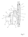
Figure 2 is a partially sectioned schematic view with parts removed for reasons of clarity of a further detail of the turbine ofFigure 1a ; -
Figures 3 and 4 are two perspective views of the detail ofFigure 2 , with parts removed for reasons of clarity; and -
Figures 5-8 show further details, once again in a schematic form, of the turbine ofFigure 1 . -
Figure 1a is a schematic and only partial illustration of a gas turbine having silo combustion chambers, designed for the production of electrical energy and having a general structure that is substantially known and is hence not described or illustrated in detail for reasons of simplicity. - In basic terms, the turbine 1 comprises a
rotor 2 and astator 3, which extend along and about a central axis A, aturbine section 4, and anair compressor 5 aligned along the axis A, and at least onesilo combustion chamber 6, in which compressed air coming from thecompressor 5 and fuel gas burn so as to produce hot gases that supply theturbine section 4. Thecompressor 5 and theturbine section 4 have stator parts supported by anouter casing 8, of which shown inFigure 1a is only a bottom portion 9 (substantially a bottom half), and rotor parts, which are fitted on acommon shaft 10 rotating about the axis A to form therotor 2. - In the non-limiting example shown in
Figure 1a , the turbine 1 comprises two silo combustion chambers 6 (in themselves known and represented only schematically by a dashed line inFigure 1a ), which extend substantially vertically above and laterally with respect to theshaft 10 on opposite sides of the turbine 1. - The turbine 1 further comprises a hot-gas
inner casing 11, set within theouter casing 8 and around therotor 2 and set axially between thecompressor 5 and theturbine section 4. Theinner casing 11 is provided with an inner throughseat 12, which is set along the axis A and in which therotor 2 is inserted and is delimited by arotor covering element 13. - With reference also to
Figure 1b , theinner casing 11 has a generally tubular shape transverse with respect to the axis A. In particular, theinner casing 11 has a substantiallytubular side wall 14 closed like a ring about a transverse axis B substantially orthogonal to the axis A. Theinner casing 11 has a pair ofopposite end openings 15, delimited by respective opposite terminal edges, which are substantially circular, of thewall 14. Theopenings 15 are set on opposite sides of the axis A and are designed for connection with respective flame pipes (not illustrated) of thecombustion chambers 6. - The
inner casing 11 moreover has a pair of central throughopenings 16 substantially perpendicular to the axis A, formed in respective opposite portions of thewall 14 and facing one thecompressor 5 and the other theturbine section 4. Housed in theopenings 16 is therotor covering element 13, which is formed by a substantially cylindrical tubular body set around therotor 2 and is provided with a radiallyexternal sealing flange 17 for front coupling with adiffuser 18 of thecompressor 5. - The casing has
opposite front plates 19, facing thecompressor 5 and theturbine section 4, set around and/or alongside theopenings 16. - The
outer casing 8 is provided withbrackets 20 for supporting and fixing theinner casing 11. In particular, thecasing 8 is provided with two pairs ofbrackets 20 set facingrespective plates 19 of theinner casing 11 and set on opposite sides of the axis A. - The
inner casing 11 is provided with as many supportingfeet 21, which extend from respectiveouter surface portions 22 of theinner casing 11, for example, from theplates 19, for resting onrespective brackets 20. - With reference also to
Figures 2-4 , eachfoot 21 has one or more circular throughholes 23, for example a pair ofholes 23 set alongside one another, engaged by respective fixing tie-rods 24 (threaded tie-rods or screws). Advantageously, theholes 23 are not threaded and have a diameter D1 substantially equal to the outer diameter of the tie-rods. - In the non-limiting example shown in
Figures 2-4 , eachfoot 21 comprises a bracket-shaped portion 25 having aseat 26 that engages aprojection 27, which extends from anouter surface portion 22 of the casing, and aconnection portion 28 provided with theholes 23 and having a substantiallyplane bottom surface 29. - Each
foot 21 rests on abracket 20. Possibly, as will be clarified hereinafter, ashim 31, constituted by a flat plate of appropriate height and perforated for the passage of a tie-rod 24, is set between thefoot 21 and thebracket 20. - The
brackets 20 are provided with circular throughholes 33 having a diameter D2 greater than the diameter D1 and set in such a way as to be substantially aligned torespective holes 23. - The
holes 33 on thebrackets 20 have a diameter D2 greater than the diameter D1 of theholes 23 of thefeet 21 and of the tie-rods 24 and such as to enable all the displacements of theinner casing 11 allowed by the machining tolerances of theinner casing 11, in particular exceeding the diameter D1 by at least the machining tolerances of thefeet 21, as will be clarified hereinafter. - Set underneath each
bracket 20 and on the side opposite to thefoot 21 resting on said bracket is afixing plate 34, which is substantially flat and has circular threaded seats 35 (preferably passing through the fixing plate 34) having a diameter substantially equal to the diameter D1. - Each tie-
rod 24 is inserted through ahole 23 and a hole 33 (as well as through a shim 31) and engages a threaded seat 35, being screwed within said threaded seat. - The method for assembly of the
inner casing 11 in accordance with the invention comprises the steps of: - providing the
resting feet 21 of theinner casing 11 with the respective throughholes 23 of diameter D1; - providing the
brackets 20 with the respective throughholes 33 of diameter D2, greater than the diameter D1 and in particular exceeding the diameter D1 by at least the machining tolerances of the inner casing 11 (specifically of the feet 21) ; - positioning the
inner casing 11 around therotor 2; - bringing the inner casing 11 (and the rotor 2) into the
outer casing 8 and precisely into thebottom portion 9 of theouter casing 8 and resting thefeet 21 onrespective brackets 20; - centring horizontally the
inner casing 11 with respect to theouter casing 8, moving horizontally (i.e., in a direction parallel to the ground) theinner casing 11 with respect to theouter casing 8; - once the horizontal centring of the
inner casing 11 has been carried out, arranging thefixing plates 34, provided with the threaded seats 35 of diameter D1, underneath thebrackets 20 on the side opposite to thefeet 21; - inserting the tie-
rods 24 of diameter D1 in theholes 23 that are made in thefeet 21 and through theholes 33 formed in thebrackets 20, engaging the threaded seats 35 of thefixing plates 34 with the tie-rods 24, and screwing the tie-rods 24 in the threaded seats 35; - fixing each
fixing plate 34 to therespective bracket 20, viawelding spots 36 or via mechanical connection; and - finally gripping the tie-
rods 24 into the respective threaded seats 35. - The difference in diameter between the
holes 23 and the holes 33 (the latter being of a diameter greater than the former) defines (for each tie-rod 24) an adjustment space 37 available for adjustment of the horizontal position of theinner casing 11. - Clearly, some of the steps indicated can be carried out in a different order from what is represented herein by way of example. For instance, it is also possible to start to insert the tie-
rods 24 into theholes rods 24, even before completing the displacements of the inner casing 11 (said displacements will be in any case allowed by the adjustment space 37, even if theholes inner casing 11 has been completed, the next step is final gripping of the tie-rods 24 and fixing of the fixingplates 34 to thebrackets 20. - To ensure also a proper vertical centring of the
inner casing 11, theshims 31 of appropriate height are used. The method hence also comprises a step of inserting one or moreflat shims 31 between eachbracket 20 and therespective foot 21 for vertical centring of theinner casing 11. - Advantageously, before final insertion of the
shims 31, the method comprises the steps of: - for each
foot 21, inserting one or more provisional standard shims between thebracket 20 and thefoot 21 until theinner casing 11 is centred vertically; - measuring the overall height (thickness) of the packs of shims thus formed on each
bracket 20 to determine the final size of theshims 31; and - replacing the provisional packs of shims with the
final shims 31 having a thickness equal to that of the packs that they replace. - To complete assembly of the
inner casing 11, the method also comprises a step of adjusting the axial play (along the axis A) between the sealingflange 17 of therotor covering element 13 and anannular seat 38, which is formed in thediffuser 18 and in which theflange 17 is housed, as shown in detail inFigure 5 . - With reference to
Figures 5-8 , theflange 17 is housed with axial play (along the axis A) in theannular seat 38 formed in aside wall 38a of thediffuser 18 and having a pair of oppositelateral sides 39 substantially orthogonal to the axis A and facing respective faces of theflange 17. - The method of the invention comprises the step of introducing arc-shaped
flat inserts 40, of a selected thickness, into theannular seat 38, between theflange 17 and one or both of thesides 39 of theannular seat 38. Theinserts 40 are selected so as to have a thickness such as to adjust the axial position of theflange 17 in theannular seat 38 and consequently the axial position of therotor covering element 13. - Preferably, the
inserts 40 are arranged on either side of theflange 17, hence between each face of theflange 17 and aside 39. - Preferably, the
inserts 40 are shaped as half-rings and a pair ofinserts 40 is used on each side of theflange 17 for covering substantially the entire circumference of theflange 17, as shown inFigures 7 and 8 (whereFigure 8 is a cross-sectional view according to the plane of trace VIII-VIII ofFigure 7 ). It is in any case understood that theinserts 40 can have a different angular extension and can be used in a number different from what is indicated herein purely by way of example. - The
inserts 40 set in the bottom portion of theannular seat 38 can be introduced into theannular seat 38 also when therotor 2 is installed, in so far as they are fixed on the outside of the horizontal middle plane P of therotor covering element 13. Accordingly, hence, theinserts 40 are first introduced into theannular seat 38 and then clamped withscrews 41 set outside of the horizontal middle plane P. - Some inserts 40 have moreover, optionally, a
deformed portion 42 so as to create a slight forcing in theannular seat 38 such as to prevent the so-called phenomenon of "vibration hammering" during operation. Said deformation is eliminated once, as a result of thermal expansion, the play present when "cold" is eliminated. For example, theportion 42 projects axially with respect to the remaining (flat) portions of theinsert 40. - The
inserts 40 can be inserted also at the end of assembly (i.e., after the operations described previously for centring the casing, with rotor installed, have been carried out) and can also be extracted and replaced without having to dismantle therotor 2. - Finally, it is clear that modifications and variations may be made to the method described and illustrated herein, without thereby departing from the scope of the annexed claims.
Claims (12)
- A method for assembling a gas turbine (1) with silo combustion chamber or chambers, in particular for assembling a hot-gas inner casing of the turbine, comprising the steps of:- providing a hot-gas inner casing (11) of the turbine (1) with resting feet (21) provided with respective first through holes (23) having a first diameter (D1);- providing an outer casing (8) of the turbine (1) with brackets (20), provided with respective second through holes (33) having a second diameter (D2), greater than the first diameter (D1);- positioning the inner casing (11) in the outer casing (8) and resting the feet (21) on respective brackets (20);- moving horizontally the inner casing (11) with respect to the outer casing (8) exploiting an adjustment space defined by the diameter difference between the first holes (23) and the second holes (33), for horizontal centring of the inner casing (11) with respect to the outer casing (8); and- before or after horizontal centring of the inner casing (11), inserting fixing tie-rods (24) through the first holes (23) and the second holes (33) and engaging with the tie-rods (24) respective threaded seats (35) formed in fixing plates (34) applied underneath respective brackets (20) on the side opposite to the feet (21).
- The method according to Claim 1, comprising, before the step of positioning the inner casing (11) in the outer casing (8), the step of arranging the inner casing (11) around a rotor (2) of the turbine, and then positioning together the rotor (2) and the inner casing (11) in the outer casing (8).
- The method according to Claim 1 or Claim 2, comprising, after engaging the threaded seats (35) of the fixing plates (34) with the tie-rods (24), the step of fixing each fixing plate (34) to the respective bracket (20), by means of welding spots (36) or via mechanical connection.
- The method according to any of the preceding claims, wherein the second holes (33) have a second diameter (D2) exceeding the first diameter (D1) by at least the machining tolerances of the inner casing (11) and specifically of the feet (21).
- The method according to any one of the preceding claims, wherein the fixing plates (34) are arranged and engaged by the tie-rods (24) before completing horizontal centring of the inner casing (11).
- The method according to any one of the preceding claims, wherein, once horizontal centring of the inner casing (11) is completed, the tie-rods (24) are finally tightened and the fixing plates (34) are fixed to the brackets (20).
- The method according to any one of the preceding claims, wherein the tie-rods (24) and the threaded seats (35) have substantially the first diameter (D1).
- The method according to any one of the preceding claims, comprising a step of vertical centring of the inner casing (11), wherein one or more flat shims (31) are inserted between each bracket (20) and the respective foot (21) for vertical centring of the inner casing (11).
- The method according to any one of the preceding claims, wherein the inner casing (11) comprises a rotor covering element (13) provided with a sealing flange (17) for front coupling to a diffuser (18), housed in an annular seat (38) formed in the diffuser; and the method comprises a step of adjustment of the axial play between the flange (17) and the corresponding annular seat (38), wherein flat arc-shaped inserts (40) of a selected thickness are inserted in the annular seat (38), between the flange (17) and one or both of respective sides (39) of the annular seat (38).
- The method according to Claim 9, wherein the inserts (40) are selected so as to have a thickness such as to adjust the axial position of the flange (17) in the annular seat (38) and consequently the axial position of the rotor covering element (13).
- The method according to Claim 9 or Claim 10, wherein the inserts (40) are fixed in the annular seat (38) and clamped therein with screws (41) arranged on the outside of a horizontal middle plane (P) of the rotor covering element (13).
- The method according to any one of Claims 9 to 11, wherein some inserts (40) have a deformed portion (42), for example projecting axially with respect to remaining flat portions of the insert (40), so as to create a slight forcing in the annular seat (38).
Applications Claiming Priority (1)
| Application Number | Priority Date | Filing Date | Title |
|---|---|---|---|
| IT001713A ITMI20091713A1 (en) | 2009-10-07 | 2009-10-07 | METHOD FOR ASSEMBLING A GAS TURBINE WITH A SILO COMBUSTION CHAMBER |
Publications (1)
| Publication Number | Publication Date |
|---|---|
| EP2312128A1 true EP2312128A1 (en) | 2011-04-20 |
Family
ID=42135983
Family Applications (1)
| Application Number | Title | Priority Date | Filing Date |
|---|---|---|---|
| EP10186848A Withdrawn EP2312128A1 (en) | 2009-10-07 | 2010-10-07 | Method for assembling a gas turbine with silo combustion chamber |
Country Status (2)
| Country | Link |
|---|---|
| EP (1) | EP2312128A1 (en) |
| IT (1) | ITMI20091713A1 (en) |
Cited By (2)
| Publication number | Priority date | Publication date | Assignee | Title |
|---|---|---|---|---|
| WO2016079223A1 (en) * | 2014-11-20 | 2016-05-26 | Siemens Aktiengesellschaft | Thermal energy machine with flow guide devices in the diffusor |
| CN113107678A (en) * | 2020-01-13 | 2021-07-13 | 安萨尔多能源瑞士股份公司 | Gas turbine |
Citations (6)
| Publication number | Priority date | Publication date | Assignee | Title |
|---|---|---|---|---|
| CH319355A (en) * | 1952-05-08 | 1957-02-15 | Parsons & Marine Eng Turbine | Flange connection for turbine housing |
| US4356698A (en) * | 1980-10-02 | 1982-11-02 | United Technologies Corporation | Staged combustor having aerodynamically separated combustion zones |
| US4458481A (en) * | 1982-03-15 | 1984-07-10 | Brown Boveri Turbomachinery, Inc. | Combustor for regenerative open cycle gas turbine system |
| US5737913A (en) * | 1996-10-18 | 1998-04-14 | The United States Of America As Represented By The Secretary Of The Air Force | Self-aligning quick release engine case assembly |
| US6442946B1 (en) * | 2000-11-14 | 2002-09-03 | Power Systems Mfg., Llc | Three degrees of freedom aft mounting system for gas turbine transition duct |
| EP1433924A2 (en) * | 2002-12-12 | 2004-06-30 | Hitachi, Ltd. | Gas turbine combustor |
-
2009
- 2009-10-07 IT IT001713A patent/ITMI20091713A1/en unknown
-
2010
- 2010-10-07 EP EP10186848A patent/EP2312128A1/en not_active Withdrawn
Patent Citations (6)
| Publication number | Priority date | Publication date | Assignee | Title |
|---|---|---|---|---|
| CH319355A (en) * | 1952-05-08 | 1957-02-15 | Parsons & Marine Eng Turbine | Flange connection for turbine housing |
| US4356698A (en) * | 1980-10-02 | 1982-11-02 | United Technologies Corporation | Staged combustor having aerodynamically separated combustion zones |
| US4458481A (en) * | 1982-03-15 | 1984-07-10 | Brown Boveri Turbomachinery, Inc. | Combustor for regenerative open cycle gas turbine system |
| US5737913A (en) * | 1996-10-18 | 1998-04-14 | The United States Of America As Represented By The Secretary Of The Air Force | Self-aligning quick release engine case assembly |
| US6442946B1 (en) * | 2000-11-14 | 2002-09-03 | Power Systems Mfg., Llc | Three degrees of freedom aft mounting system for gas turbine transition duct |
| EP1433924A2 (en) * | 2002-12-12 | 2004-06-30 | Hitachi, Ltd. | Gas turbine combustor |
Cited By (4)
| Publication number | Priority date | Publication date | Assignee | Title |
|---|---|---|---|---|
| WO2016079223A1 (en) * | 2014-11-20 | 2016-05-26 | Siemens Aktiengesellschaft | Thermal energy machine with flow guide devices in the diffusor |
| CN107002509A (en) * | 2014-11-20 | 2017-08-01 | 西门子股份公司 | Heat energy machine with the guiding device in diffuser |
| CN113107678A (en) * | 2020-01-13 | 2021-07-13 | 安萨尔多能源瑞士股份公司 | Gas turbine |
| EP3848556A1 (en) * | 2020-01-13 | 2021-07-14 | Ansaldo Energia Switzerland AG | Gas turbine engine having a transition piece with inclined cooling holes |
Also Published As
| Publication number | Publication date |
|---|---|
| ITMI20091713A1 (en) | 2011-04-08 |
Similar Documents
| Publication | Publication Date | Title |
|---|---|---|
| US8578584B2 (en) | Method for centering engine structures | |
| US8448444B2 (en) | Method and apparatus for mounting transition piece in combustor | |
| US7923890B2 (en) | Apparatus for generator stator mounting | |
| UA80536C2 (en) | Turbo-machine with cooled ring segments | |
| US20070130958A1 (en) | Combustor flow sleeve attachment system | |
| US10563541B2 (en) | Securing device, steam turbine, and rotary machine manufacturing method and assembly method | |
| US9435535B2 (en) | Combustion liner guide stop and method for assembling a combustor | |
| EP2312128A1 (en) | Method for assembling a gas turbine with silo combustion chamber | |
| US6499993B2 (en) | External dilution air tuning for dry low NOX combustors and methods therefor | |
| CN105765175A (en) | Eccentric coupling device and method for coupling mating casings in a turbomachine | |
| US6331110B1 (en) | External dilution air tuning for dry low NOx combustors and methods therefor | |
| EP1793097A1 (en) | Apparatus for assembling a gas turbine engine | |
| KR101925234B1 (en) | Fixing device, rotary machine, manufacturing method of rotary machine, assembly method and separation method | |
| US8955328B2 (en) | Burner arrangement | |
| US20150113805A1 (en) | Method of assembling a gas turbine enclosure | |
| US11187411B2 (en) | Combustion chamber assembly with shingle part and positioning facility | |
| CN113383480A (en) | Fixing of stator segments | |
| CN102482946B (en) | Hot Gas Ducts and Duct Divider Units | |
| KR102924672B1 (en) | Turbine assembly and method of assembling the turbine assembly | |
| US6786695B2 (en) | Rod and groove for sealing or adjusting axial location of turbine parts and methods of use | |
| RU169354U1 (en) | THERMAL INSULATING DRILLING HOUSING | |
| CN102909411B (en) | Fixture and method for transforming the shell in turbine system | |
| US20210396175A1 (en) | Mid-frame section of a gas turbine engine and corresponding method of adjusting radial rotor clearance | |
| WO2007032311A1 (en) | Blade tip clearance control structure of gas turbine | |
| US11105510B2 (en) | Alignment tools and methods for assembling combustors |
Legal Events
| Date | Code | Title | Description |
|---|---|---|---|
| PUAI | Public reference made under article 153(3) epc to a published international application that has entered the european phase |
Free format text: ORIGINAL CODE: 0009012 |
|
| AK | Designated contracting states |
Kind code of ref document: A1 Designated state(s): AL AT BE BG CH CY CZ DE DK EE ES FI FR GB GR HR HU IE IS IT LI LT LU LV MC MK MT NL NO PL PT RO RS SE SI SK SM TR |
|
| AX | Request for extension of the european patent |
Extension state: BA ME |
|
| 17P | Request for examination filed |
Effective date: 20111020 |
|
| STAA | Information on the status of an ep patent application or granted ep patent |
Free format text: STATUS: THE APPLICATION IS DEEMED TO BE WITHDRAWN |
|
| 18D | Application deemed to be withdrawn |
Effective date: 20150501 |