EP2312121A1 - Internal combustion engine with rotating cylinders - Google Patents
Internal combustion engine with rotating cylinders Download PDFInfo
- Publication number
- EP2312121A1 EP2312121A1 EP10187858A EP10187858A EP2312121A1 EP 2312121 A1 EP2312121 A1 EP 2312121A1 EP 10187858 A EP10187858 A EP 10187858A EP 10187858 A EP10187858 A EP 10187858A EP 2312121 A1 EP2312121 A1 EP 2312121A1
- Authority
- EP
- European Patent Office
- Prior art keywords
- engine
- piston
- rotor assembly
- chamber
- rotation
- Prior art date
- Legal status (The legal status is an assumption and is not a legal conclusion. Google has not performed a legal analysis and makes no representation as to the accuracy of the status listed.)
- Withdrawn
Links
- 238000002485 combustion reaction Methods 0.000 title claims abstract description 20
- 230000033001 locomotion Effects 0.000 claims description 18
- 238000007789 sealing Methods 0.000 claims description 8
- 230000002093 peripheral effect Effects 0.000 claims description 6
- 238000004891 communication Methods 0.000 claims description 2
- 238000006073 displacement reaction Methods 0.000 abstract description 8
- 208000006011 Stroke Diseases 0.000 description 12
- 238000007906 compression Methods 0.000 description 8
- 239000000446 fuel Substances 0.000 description 8
- 230000006835 compression Effects 0.000 description 7
- 239000000203 mixture Substances 0.000 description 6
- 239000007789 gas Substances 0.000 description 5
- 230000008901 benefit Effects 0.000 description 4
- 230000005540 biological transmission Effects 0.000 description 4
- 238000002347 injection Methods 0.000 description 3
- 239000007924 injection Substances 0.000 description 3
- 238000004519 manufacturing process Methods 0.000 description 3
- 230000007246 mechanism Effects 0.000 description 3
- 239000000243 solution Substances 0.000 description 3
- 235000014676 Phragmites communis Nutrition 0.000 description 2
- 238000001816 cooling Methods 0.000 description 2
- 230000003993 interaction Effects 0.000 description 2
- 239000000126 substance Substances 0.000 description 2
- 235000011437 Amygdalus communis Nutrition 0.000 description 1
- 241001275902 Parabramis pekinensis Species 0.000 description 1
- 241000220304 Prunus dulcis Species 0.000 description 1
- 208000027418 Wounds and injury Diseases 0.000 description 1
- 230000001133 acceleration Effects 0.000 description 1
- 230000009471 action Effects 0.000 description 1
- 235000020224 almond Nutrition 0.000 description 1
- 230000008859 change Effects 0.000 description 1
- 238000006243 chemical reaction Methods 0.000 description 1
- 230000008878 coupling Effects 0.000 description 1
- 238000010168 coupling process Methods 0.000 description 1
- 238000005859 coupling reaction Methods 0.000 description 1
- 230000006378 damage Effects 0.000 description 1
- 230000003247 decreasing effect Effects 0.000 description 1
- 230000001934 delay Effects 0.000 description 1
- 230000001419 dependent effect Effects 0.000 description 1
- 238000004880 explosion Methods 0.000 description 1
- 230000005484 gravity Effects 0.000 description 1
- 208000014674 injury Diseases 0.000 description 1
- 238000009434 installation Methods 0.000 description 1
- 210000004072 lung Anatomy 0.000 description 1
- 239000000463 material Substances 0.000 description 1
- 238000011084 recovery Methods 0.000 description 1
- 230000009467 reduction Effects 0.000 description 1
- 230000000284 resting effect Effects 0.000 description 1
- 230000002000 scavenging effect Effects 0.000 description 1
- 238000004513 sizing Methods 0.000 description 1
- 238000005406 washing Methods 0.000 description 1
Images


Classifications
-
- F—MECHANICAL ENGINEERING; LIGHTING; HEATING; WEAPONS; BLASTING
- F01—MACHINES OR ENGINES IN GENERAL; ENGINE PLANTS IN GENERAL; STEAM ENGINES
- F01B—MACHINES OR ENGINES, IN GENERAL OR OF POSITIVE-DISPLACEMENT TYPE, e.g. STEAM ENGINES
- F01B13/00—Reciprocating-piston machines or engines with rotating cylinders in order to obtain the reciprocating-piston motion
- F01B13/04—Reciprocating-piston machines or engines with rotating cylinders in order to obtain the reciprocating-piston motion with more than one cylinder
- F01B13/045—Reciprocating-piston machines or engines with rotating cylinders in order to obtain the reciprocating-piston motion with more than one cylinder with cylinder axes arranged substantially tangentially to a circle centred on main shaft axis
-
- F—MECHANICAL ENGINEERING; LIGHTING; HEATING; WEAPONS; BLASTING
- F02—COMBUSTION ENGINES; HOT-GAS OR COMBUSTION-PRODUCT ENGINE PLANTS
- F02B—INTERNAL-COMBUSTION PISTON ENGINES; COMBUSTION ENGINES IN GENERAL
- F02B57/00—Internal-combustion aspects of rotary engines in which the combusted gases displace one or more reciprocating pistons
- F02B57/08—Engines with star-shaped cylinder arrangements
Definitions
- the present invention refers to an internal combustion engine, in particular to a rotating cylinder/piston engine.
- the object of the present invention is hence to manufacture an engine with rotary pistons which has a reduced bulk, due to the extreme simplification of components, which is usable for any type of supply, which reduces the inertia forces due to the moving masses with respect to the crank gear and which allows directly the supercharge necessary for the increase of the specific power for the availability of a larger amount of comburent with respect to the normally taken in one, hence being able to provide to the cooling also with a stationary vehicle.
- a further object is to offer an engine wherein it is possible to maintain the traditional and reliable cylindrical combustion chamber, so as to be able to increase the number of cylinders with the same piston displacement for improving the balancing and reduce noise.
- An even further object is to provide an engine wherein the efficiencies of the Otto and Diesel cycles can be improved by varying the relative duration of the cycles with respect to those of the fixed alternate motion (typical of the connecting-rod/crank transmission) and the adjustment of the duration of the phases, consequently of the advances and of the delays of the valve lifts, also depending on rotation speed, by acting on a single central cam.
- a further object is to manufacture an engine which is capable of using the kinetic energy developed by the rotating exhaust gases.
- an internal combustion engine of the type comprising at least one casing defining inside the same a chamber within which a rotor assembly is rotatingly mounted provided with at least one piston slidingly mounted of alternate motion on a plane orthogonal to a rotation axis of the rotor element, wherein at least one piston is slideable within a respective cylinder (wherein the combustion of the fuel mixture occurs) integral in rotation with said rotor assembly rotatingly mounted offset with respect to the locus of the constraint points of one foot end of said piston.
- the chamber is defined between two side walls of the casing and by one curved, peripheral wall, sandwiched between the two side walls, the perimeter of which is determined by said peripheral wall.
- the location of the constraint points of the foot end is a circular line.
- the foot end of said at least one piston is hinged on rotary, circular thrust bearing means centred on an axis offset with respect to said main rotation axis.
- the inner wall of the housing chamber is circular and houses an equally circular rotor assembly body.
- an inlet port equipped with valve means is provided, said inlet port being in communication with said chamber.
- an engine shaft is provided - through which a torque is extracted - integral in rotation with the rotor assembly, According to a different aspect, the engine shaft is integral in rotation with said thrust-bearing means.
- the engine shown in figs. 1 and 2 has, in a manner known per se, an engine casing 1 within which there is defined a housing chamber 2 of the rotor block, of the piston and of the cylinder.
- chamber 2 there is housed, mounted rotating on an axis a-a', a block or cylinder body 3 within which there is slideably mounted a single piston 4.
- said block is integral with a rotor element 5 mounted on casing 1 by means of suitable bearings 6a and 6b.
- Chamber 2 is defined between two flat, parallel walls of cylinder block 1 and by a curved peripheral wall 6, which defines internally also a guiding and sealing surface.
- wall 6 is defined by generatrixes parallel to the rotation axis a-a' of rotor 5.
- the cylinder block or body 3 has internally a cylindrical cavity, covered by a suitable liner, to cause piston 4 to slide therein, in a manner traditional per se.
- the external shape of block 3 in the embodiment of figs. 1-2 is circular with symmetry axis corresponding to rotation axis a-a' ; the sizing of block 3 and the mounting thereof with respect to chamber 2 is such that there is at least one tangential point with guiding wall 6, for example the point referred to as 6 ' in fig. 1 . Due to the circular shape of block 3, with its centre on rotation axis a-a ' , the point of contact 6' is fixed.
- roller or slider 7 steadily connected with a pin 9, free to rotate and intended to slide - with the lowest possible friction - on the internal guiding surface of curved wall 6.
- Roller 7 is meant to rest in a sealing manner on the inner surface of wall 6, in the point referred to as 10, with which it establishes a slider constraint for piston 4 and at the same time a seal.
- Point of contact 10 is movable, chasing the position of roller 7 about rotation axis a-a ' .
- wall 6 Since during the rotation of body 3 the piston works within its cylinder - sliding with an alternate motion - remaining resting (through roller 7) on wall 6, the curvature of said wall is capable of determining the alternate motion law of piston 4.
- wall 6 may have a circular trend, or an elliptical one as visible in fig. 1 .
- chamber 2 Due to the contact points which are established in 6' (fixed) and 10 (movable), in an original way, the inner volume of chamber 2 is divided into two varying-volume compartments (to the left and to the right of the piston, respectively, in fig. 1 ), which allows to use chamber 2 as a compression lung for comburent air, as will be better highlighted further on.
- an inlet port of cylinder 3a On one side of the cylinder/rotor block 3, 4 (the left one in fig. 1 ) there is provided an inlet port of cylinder 3a, for example closed by a reed valve. Inlet port 3a communicates with chamber 2. Another external inlet port, provided to allow the immission of comburent air into chamber 2, is provided on casing 1. In a suitable position (not shown) there is furthermore provided an injector or carburettor to add vaporised fuel to the immission air, thereby obtaining the fuel mixture.
- the two varying-volume compartments, defined in chamber 2, hence allow to effectively draw and compress the fuel mixture.
- the left part of chamber 2 during the clockwise rotation of the piston/cylinder assembly, reduces in volume and hence compresses the air contained therein, before it can be introduced into cylinder 3 through inlet 3a, upon opening of the reed valve.
- the half-chamber to the right of piston 4 widens in the same rotation, drawing air from outside engine casing 1.
- the interaction between the cylinder/piston assembly and chamber 2 defines a sort of compressor for the air to be introduced into cylinder 3.
- a mixture injector 11, with relative driving mechanisms 12, arranged directly in the block of the rotary cylinder/rotor may be provided.
- a system for driving the injection pump may be shaped as a cam follower 12 kept projecting with respect to cylinder 3: the interaction of such follower 12 with the guiding surface 7 - which acts as cam surface during the rotation of cylinder body 3 - determines the actuation of the injector pump 11 with the desired timing.
- the engine may provide oil supplies to keep the piston travel path and all the mutually moving parts in contact lubricated.
- Fig. 1 shows a single engine casing 1 wherein a piston and relative cylinder is housed.
- a similar engine is conceivable wherein a plurality of casings such as the ones shown in figs. 1 and 2 are arranged side by side with the external inlet and exhaust ports mutually coupled.
- two external inlet ports of adjacent casings, coupled one opposite the other, are connected to a common manifold or conduit (not shown), whereto the intake air supply converges.
- the outlet ports may be connected to a single exhaust gas outlet.
- the operation of the engine according to this embodiment provides that the combustion occurs in a traditional way between piston 4 and the inner ceiling of the cylinder of rotary block 3.
- the alternate movement of piston 4 is guided - instead of by a traditional crank gear - by the coupling between roller 7 and guiding surface 6.
- a tangential thrust component is determined which keeps in contact this assembly, including piston 4, with respect to engine axis a-a'.
- Chamber/compressor 2 causes the air, at a pressure higher than atmospheric pressure, to enter the combustion chamber facilitating the natural suction of piston 4 within its cylinder.
- the mixture is hence formed which can explode due to the further compression by piston 4 in the combustion chamber (for example in diesel engines) or due to the ignition by a suitable spark plug 13 or other similar means (as occurs in standard gasoline engines).
- the rotation of rotor 3, induced by the displacement of piston 4 following the combustion in the relative cylinder transfers the motion, by means of a suitable transmission (not shown), to the moving parts of the load, for example the wheels of a vehicle.
- casing 1' houses a rotary body 3' wherein a pair of cylindrical chambers 14 and 15 is obtained, associated with respective pistons 16 and 17, mounted on the same rotor.
- the two chambers 14 and 15 open in two opposite directions, so as to house pistons which move with parallel but opposite alternate motion. It is therefore possible to have 4 strokes per revolution, balancing them two by two.
- fig. 4 shows an interrupted-section view, wherein the lower part is taken along the line IV-IV of fig. 3 , while the upper part represents a similar section but with rotor assembly 3 rotated by 90° in the direction shown by arrow F (phase wherein the pistons are in the position shown by a phantom line in fig. 3 ).
- Figs. 5 and 6 show another embodiment conceptually equivalent to the one with two pistons shown in figs. 3 and 4 .
- the alternate displacement of the pistons is created by establishing a relative rotation offset between the point of constraint of the pistons and that of the body of the cylindrical chambers, it is possible - should one wish to establish circular trajectories and not trajectories with an asymmetrical ellipsoidal shape as exemplifyingly shown in fig. 1 - to constrain the pin of the pistons to a rotary thrust bearing, having the same centre as the rotary block, arranged within the casing 1''.
- the rotary body with cylinder chambers 30 rotates with an axis b-b' and chambers 14" and 15 " arranged symmetrically with respect to the rotation axis; unlike the second embodiment illustrated, this third embodiment provides that constraint points 80 and 81 of pistons 16 " and 17" are hinged to respective portions of thrust bearings R and R' arranged in rotation about a ring 82 with an offset centre (hence eccentric) with respect to the main rotation axis b-b'.
- the practical implementation provides that the pistons not be guided by the rollers on an external guide (corresponding to the inner surface of the compression chamber), but be constrained internally, so as to allow the further reduction of the centrifugal forces and the frictions on the rollers.
- the rotation axis of the thrust bearings determines the guidance of the piston movements, replacing the external guide, thereby making it possible to reduce the elongation and the weight of the piston, and consequently the forces deriving from the alternate movement of the masses.
- the two thrust bearing portions R and R' having an angular extension preferably below 120°, during operation (slidingly guided between a pair of annular guides, internal guide 82 and external guide 83), move alternatively closer and further apart, without ever coming into contact and allowing the out-of-phase alternate motions of the two pistons 16 " and 17 ".
- Figs. 7 and 8 show a fourth embodiment.
- the operation principle is fully equivalent to the third embodiment illustrated.
- the system is simplified because a single piston is provided per thrust bearing.
- it is possible to lay side-by-side a plurality of casings 1"' to obtain a multi-cylinder engine.
- the engine according to the present invention it is possible to advantageously do without some components traditionally found in internal combustion engines, such as the engine shaft (reduced to the point where the axis a-a' is fitted).
- the circular shape of the cylinder blocks requires - the cylinder displacement being the same - a much smaller bulk with respect to traditional linear or V shaped engines, thus allowing the simultaneous presence of an internal combustion engine and of an electrical motor, as required in hybrid-propulsion vehicles, increasingly popular today.
- the engine according to the present invention may be manufactured both as an Otto-cycle engine and as a Diesel-cycle engine.
- an internal combustion engine the use of a carburettor or of a mechanical or electronic injection system can be provided.
- the engine may be manufactured both as a traditional 4-stroke engine, and as a 2-stroke engine.
- a single-lobe architecture of the guiding surface 6 may be provided, so as to allow more time for phase completion, due to a larger amount of overpressure air through the intake from the compression chamber.
- valves for intake and discharge which will be operated with cyclical alternation and double wash every 2 revolutions of the engine, hence at half the speed compared to the rotor.
- a gear integral with the rotor is provided to mesh with a planetary gear which rotates at half the speed for controlling any valves.
- the cycle occurs in a 360° revolution of the rotor for the combustion-wash-supply-compression, due to the single lobe, external, elliptical guide.
- the external guide could be defined bilobate, thus obtaining the opportunity of increasing the number of phases strokes (hence of useful phases) the engine revolutions being the same.
- the rotary cylinder engine according to the present invention allows to combine the advantages of the rotary engine, such as the Wankel engine, with the advantages of the cylinder-piston assembly of conventional linear or V-shaped engines, definitely more accurate in terms of sealing and with smaller load losses, hence with greater efficiency.
- the efficiency is hence higher both than the conventional, rotary cylinder engine, such as the Wankel engine, due to smaller load losses, and to the linear or V-shaped engine due to the smaller weight and due to the smaller number of moving components, which carry frictions.
- the implementation of the engine as compressor rotor furthermore allows to obtain compressed air with which to effectively cool exhaust gases, thereby reducing the noise also with a stationary vehicle and increasing safety, since the risk of accidental burn injury is reduced, if not virtually eliminated and even the risk of igniting flammable material which may come in contact with the exhaust pipe (for example hay or the like).
- the compressed air generated by compression chamber 2 may be used to keep driving the alternator, thus allowing energy recovery during vehicle operation.
- a further force is generated due to the changing of the kinetic energies, in turn determined by the centrifugal or centripetal trajectories of the piston having decreasing or increasing instant rotation radiuses.
- Such force generates thrusts on the cylinder walls which proved advantageous for the motion, further exploiting the energy produced by the expansion of burnt gases.
- the engine design provides that the axis wherefrom propulsion power is drawn be the motor rotation shaft (integral in rotation with the cylinder wherein the piston slides), a different configuration may also be possible.
- torque transmission through the rotor may induce torque counter-reactions between the piston and the cylinder such as to generate excessive frictions during the alternate sliding of the piston.
- An alternative embodiment, illustrated in figs. 9-10 hence provides that the driving torque be drawn from the thrust bearings - when provided - which the piston foot is constrained to.
- a cylindrical thrust bearing 90 is rotatably mounted offset with respect to the rotation axis of rotor 91. Said rotor is integral with the cylinder 92 wherein piston 93 is sliding. On the thrust bearing - as seen also above - the constraint foot of piston 93 is hinged, for example by means of a pin 93a.
- Thrust bearing 90 comes out of the engine block or engine casing 95 with a power takeoff 94.
- the engine shaft of rotor 91 is preferably supported by external bearings (not shown) or by other suitably lubricated, plain bearing means, arranged between the peripheral surfaces 90a of the rotor and an internal circular surface 95a of engine casing 95.
- connection flaps 96 Preferably, in the case of installation of two pistons, the two parallel thrust bearings (one of the two not shown) are joined by two connection flaps 96, so as to create a sort of crank gear similar to one of an ordinary type, with better rigidity.
- the thrust-bearing/crank gear/rotor relative motion remains equivalent to the one described above with reference to the other embodiments, but piston 93 transmits only axial forces (generated by the explosion of the fuel mixture), with no side pushes; connection flaps 96 improve air compression, wash and supply.
Landscapes
- Engineering & Computer Science (AREA)
- Mechanical Engineering (AREA)
- General Engineering & Computer Science (AREA)
- Chemical & Material Sciences (AREA)
- Combustion & Propulsion (AREA)
- Transmission Devices (AREA)
- Cylinder Crankcases Of Internal Combustion Engines (AREA)
Abstract
An internal combustion engine is described, of the type comprising at least one casing (1, 1', 1", 1"') defining within the same a chamber (2) within which a rotor assembly (3, 3', 30) is rotatably mounted, provided with at least one piston (4, 16, 17, 16, 16", 17") slidingly mounted with an alternate displacement on a plane orthogonal to a rotation axis (a-a', b-b') of the rotor assembly, said at least one piston (4, 16, 17, 16, 16", 17") being slideable in a respective cylinder integral in rotation with said rotor assembly (3, 3', 30) rotatably mounted offset with respect to the locus of the constraint points of a foot end (8) of said piston (4, 16, 17, 16, 16", 17") .
Description
- The present invention refers to an internal combustion engine, in particular to a rotating cylinder/piston engine.
- Internal combustion engines, such as internal combustion engines or diesel engines, are largely widespread in the automotive world, as well as in that of other types of vehicles. Such engines, for a series of reasons, have intrinsically extremely low efficiency rates, both due to the affected thermodynamic cycle (which has a theoretical efficiency below 30%), and to other factors, such as the fact that a good deal of the energy is employed to keep the engine running, partly for carrying the weight of the sole vehicle and only a fraction of about 10% for carrying passengers and loads. It is evident that, especially in case of fuel price increases with respect to when the first engines were manufactured, even small efficiency differences may determine the success of a certain vehicle.
- This situation caused a majority of the studies currently under way to be aimed at the manufacturing of efficient engines; consequently, 4-stroke and 2-stroke internal combustion engines supplied by light fuels, and hence fast like the ones used for races and derived therefrom for cars and motorcycles, have lately been susceptible of a smaller development over slower diesel engines, but which are capable of improving efficiencies by scaling fuel injection during the stroke stage. New-generation Diesel engines are able to perform such scaling partly at constant volume and partly at constant pressure (Sabathè) by varying the duration of the phases according to the rpm; however, it is not possible to change the relative duration of the alternated motion, governed by the cyclical alternations of the piston motion allowed by the connecting-rod/crank mechanism.
- Generically, in order to obtain greater specific power and better efficiencies, it is provided to supercharge the engines with comburent with the energy obtained from exhaust gases or from the engine itself with apparatuses comprising separate and bulky compressors and transmissions.
- It has furthermore been found that the bulk of current engines is becoming an ever more felt problem, since the space taken up by casing, pistons, connecting rods, crank shafts and valves on cylinder heads requires remarkable volumes which could otherwise prove useful for vehicle habitability, particularly in hybrid-traction vehicles, where more than one engine must be housed in the same vehicle compartment.
- Moreover, excessive bulk implies - during the engine planning phase - the need to boost the piston displacement and to find solutions which solve excessive vibrations, which sometimes force designers to devise shafts with rotating eccentric masses, and - consequently - against noise.
- In order to find alternative solutions to the conventional engine with parallel pistons, it has been opted for studying rotary-engine configurations.
- In the past, some airplanes were equipped with rotary cylindrical engines with peripheral stroke chambers, consisting of connecting rod and central, fixed, eccentric crank button. Similarly, in some simple steam machines, the cylinder was allowed small angular displacements to invest directly on its own axis the crank button during the rotation of the engine shaft, so as not to interfere with the connecting rod.
- Again, according to the prior art, steam engines with rotary cylinders and radial pistons acting with rolls or sliding blocks on outer circular casing offset with respect to the centre of rotation thereof have already been proposed; 3-cylinder engines (RUTH) and 4-cylinder engines (ALMOND), both with central disc-shaped distributors and slow hydraulic engines, with radial cylinders, acting through rolls on an external, multiple-lobe guide path.
- None of these engines, however, was successful in conventional vehicles for transportation on the ground. Recently new rotary engines have been developed, such as the Wankel engine, which have proved sufficiently functional to find various practical applications, demonstrating that they have some advantages and especially reduced bulks compared to conventional linear engines. However, remarkable problems have been detected, determined by the rotor morphology: as a matter of fact, the rotor provided with edges has a precarious sealing in the combustion chamber, which leads to still consider as irreplaceable the better functionality of the conventional cylindrical combustion chamber. Moreover, it has been detected that the efficiency accomplished by them is totally insufficient for current market requirements.
- The object of the present invention is hence to manufacture an engine with rotary pistons which has a reduced bulk, due to the extreme simplification of components, which is usable for any type of supply, which reduces the inertia forces due to the moving masses with respect to the crank gear and which allows directly the supercharge necessary for the increase of the specific power for the availability of a larger amount of comburent with respect to the normally taken in one, hence being able to provide to the cooling also with a stationary vehicle.
- A further object is to offer an engine wherein it is possible to maintain the traditional and reliable cylindrical combustion chamber, so as to be able to increase the number of cylinders with the same piston displacement for improving the balancing and reduce noise.
- An even further object is to provide an engine wherein the efficiencies of the Otto and Diesel cycles can be improved by varying the relative duration of the cycles with respect to those of the fixed alternate motion (typical of the connecting-rod/crank transmission) and the adjustment of the duration of the phases, consequently of the advances and of the delays of the valve lifts, also depending on rotation speed, by acting on a single central cam.
- A further object is to manufacture an engine which is capable of using the kinetic energy developed by the rotating exhaust gases.
- The above-said objects are achieved by means of an engine as defined in its essential elements in the attached claims.
- In particular, according to a first aspect of the invention an internal combustion engine is provided of the type comprising at least one casing defining inside the same a chamber within which a rotor assembly is rotatingly mounted provided with at least one piston slidingly mounted of alternate motion on a plane orthogonal to a rotation axis of the rotor element, wherein at least one piston is slideable within a respective cylinder (wherein the combustion of the fuel mixture occurs) integral in rotation with said rotor assembly rotatingly mounted offset with respect to the locus of the constraint points of one foot end of said piston.
- According to a further aspect the chamber is defined between two side walls of the casing and by one curved, peripheral wall, sandwiched between the two side walls, the perimeter of which is determined by said peripheral wall.
- According to yet another aspect the location of the constraint points of the foot end is a circular line. In particular, the foot end of said at least one piston is hinged on rotary, circular thrust bearing means centred on an axis offset with respect to said main rotation axis.
- According to a preferred aspect, the inner wall of the housing chamber is circular and houses an equally circular rotor assembly body.
- On said rotor assembly an inlet port equipped with valve means is provided, said inlet port being in communication with said chamber.
- According to an aspect, an engine shaft is provided - through which a torque is extracted - integral in rotation with the rotor assembly, According to a different aspect, the engine shaft is integral in rotation with said thrust-bearing means.
- Further advantageous features of the invention are defined in the other dependent claims.
- Further details on the engine according to the invention will in any case be more evident from the following description of some preferred embodiments of the same, given by way of example and illustrated in the accompanying drawings, wherein:
-
fig. 1 is a schematic, longitudinal cross-section view, transversally to the engine shaft, of a first embodiment of the present invention concerning a single-cylinder engine; -
fig. 2 is a cross-section view, taken along the line II-II offig. 1 ; -
fig. 3 is a view similar to that offig. 1 of a second embodiment of the present invention concerning a 2-cylinder engine; -
fig. 4 is an interrupted-section view, according to two different engine phases, the lower part taken along the line IV-IV offig. 3 and the upper part offset by 90°; -
fig. 5 and fig. 6 are views similar to those offigs. 1 and 2 of a different embodiment, with a circular outside guide for a 2-cylinder engine; -
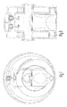
fig. 7 and fig. 8 are views similar tofigs. 1 and 2 of a different embodiment, with a circular outside guide for a single-cylinder engine; and -
figs. 9 and 10 are views of a further embodiment, with a power takeoff integral in rotation with the thrust-bearing of the piston. - The engine shown in
figs. 1 and 2 has, in a manner known per se, an engine casing 1 within which there is defined a housing chamber 2 of the rotor block, of the piston and of the cylinder. - According to the invention, in chamber 2 there is housed, mounted rotating on an axis a-a', a block or cylinder body 3 within which there is slideably mounted a single piston 4. In order to allow the rotation of cylinder block 3, said block is integral with a rotor element 5 mounted on casing 1 by means of suitable bearings 6a and 6b.
- Chamber 2 is defined between two flat, parallel walls of cylinder block 1 and by a curved peripheral wall 6, which defines internally also a guiding and sealing surface. For such purpose, wall 6 is defined by generatrixes parallel to the rotation axis a-a' of rotor 5.
- The cylinder block or body 3 has internally a cylindrical cavity, covered by a suitable liner, to cause piston 4 to slide therein, in a manner traditional per se.
- The external shape of block 3 in the embodiment of
figs. 1-2 is circular with symmetry axis corresponding to rotation axis a-a' ; the sizing of block 3 and the mounting thereof with respect to chamber 2 is such that there is at least one tangential point with guiding wall 6, for example the point referred to as 6' infig. 1 . Due to the circular shape of block 3, with its centre on rotation axis a-a', the point of contact 6' is fixed. - At the bottom end 8 of piston 4 there is provided a roller or slider 7 steadily connected with a pin 9, free to rotate and intended to slide - with the lowest possible friction - on the internal guiding surface of curved wall 6.
- Roller 7 is meant to rest in a sealing manner on the inner surface of wall 6, in the point referred to as 10, with which it establishes a slider constraint for piston 4 and at the same time a seal. Point of
contact 10 is movable, chasing the position of roller 7 about rotation axis a-a'. - Since during the rotation of body 3 the piston works within its cylinder - sliding with an alternate motion - remaining resting (through roller 7) on wall 6, the curvature of said wall is capable of determining the alternate motion law of piston 4. For example, wall 6 may have a circular trend, or an elliptical one as visible in
fig. 1 . - Due to the contact points which are established in 6' (fixed) and 10 (movable), in an original way, the inner volume of chamber 2 is divided into two varying-volume compartments (to the left and to the right of the piston, respectively, in
fig. 1 ), which allows to use chamber 2 as a compression lung for comburent air, as will be better highlighted further on. - On one side of the cylinder/rotor block 3, 4 (the left one in
fig. 1 ) there is provided an inlet port of cylinder 3a, for example closed by a reed valve. Inlet port 3a communicates with chamber 2. Another external inlet port, provided to allow the immission of comburent air into chamber 2, is provided on casing 1. In a suitable position (not shown) there is furthermore provided an injector or carburettor to add vaporised fuel to the immission air, thereby obtaining the fuel mixture. - The two varying-volume compartments, defined in chamber 2, hence allow to effectively draw and compress the fuel mixture. In particular, with reference to
fig. 1 , the left part of chamber 2, during the clockwise rotation of the piston/cylinder assembly, reduces in volume and hence compresses the air contained therein, before it can be introduced into cylinder 3 through inlet 3a, upon opening of the reed valve. Vice versa, the half-chamber to the right of piston 4 widens in the same rotation, drawing air from outside engine casing 1. - In substance, the interaction between the cylinder/piston assembly and chamber 2 defines a sort of compressor for the air to be introduced into cylinder 3.
- In case of a direct ignition engine, on the head portion of cylinder 3 there is furthermore provided a sparking plug 13.
- Optionally, a mixture injector 11, with relative driving mechanisms 12, arranged directly in the block of the rotary cylinder/rotor may be provided. Advantageously, it is possible to exploit the rotary movement of the cylinder to cause the action of injector 11 without having to draw the motion from external mechanisms. As shown in
fig. 1 , for example, a system for driving the injection pump may be shaped as a cam follower 12 kept projecting with respect to cylinder 3: the interaction of such follower 12 with the guiding surface 7 - which acts as cam surface during the rotation of cylinder body 3 - determines the actuation of the injector pump 11 with the desired timing. - Moreover, the engine may provide oil supplies to keep the piston travel path and all the mutually moving parts in contact lubricated.
-
Fig. 1 shows a single engine casing 1 wherein a piston and relative cylinder is housed. However, a similar engine is conceivable wherein a plurality of casings such as the ones shown infigs. 1 and 2 are arranged side by side with the external inlet and exhaust ports mutually coupled. In such case, two external inlet ports of adjacent casings, coupled one opposite the other, are connected to a common manifold or conduit (not shown), whereto the intake air supply converges. In a similar way the outlet ports may be connected to a single exhaust gas outlet. - As can be guessed, the operation of the engine according to this embodiment provides that the combustion occurs in a traditional way between piston 4 and the inner ceiling of the cylinder of rotary block 3. The alternate movement of piston 4 is guided - instead of by a traditional crank gear - by the coupling between roller 7 and guiding surface 6. A tangential thrust component is determined which keeps in contact this assembly, including piston 4, with respect to engine axis a-a'.
- Chamber/compressor 2 causes the air, at a pressure higher than atmospheric pressure, to enter the combustion chamber facilitating the natural suction of piston 4 within its cylinder. The mixture is hence formed which can explode due to the further compression by piston 4 in the combustion chamber (for example in diesel engines) or due to the ignition by a suitable spark plug 13 or other similar means (as occurs in standard gasoline engines). The rotation of rotor 3, induced by the displacement of piston 4 following the combustion in the relative cylinder, transfers the motion, by means of a suitable transmission (not shown), to the moving parts of the load, for example the wheels of a vehicle.
- In case it is necessary to boost the compressor, it is possible to provide suitable surfaces of inflow blades which allow the access of more air for the overpressure supply for washing, in case of 2-stroke engines, or which enrich the intake, in case of 4-stroke engines.
- In the embodiment shown in
figs. 3 and 4 , instead of a single cylinder, casing 1' houses a rotary body 3' wherein a pair ofcylindrical chambers respective pistons 16 and 17, mounted on the same rotor. In particular, the twochambers - For the rest, the operation principle of this embodiment is equivalent to the one of the first embodiment.
- For a better understanding it must be noticed that
fig. 4 shows an interrupted-section view, wherein the lower part is taken along the line IV-IV offig. 3 , while the upper part represents a similar section but with rotor assembly 3 rotated by 90° in the direction shown by arrow F (phase wherein the pistons are in the position shown by a phantom line infig. 3 ). -
Figs. 5 and 6 show another embodiment conceptually equivalent to the one with two pistons shown infigs. 3 and 4 . In this case, starting from the assumption that the alternate displacement of the pistons is created by establishing a relative rotation offset between the point of constraint of the pistons and that of the body of the cylindrical chambers, it is possible - should one wish to establish circular trajectories and not trajectories with an asymmetrical ellipsoidal shape as exemplifyingly shown infig. 1 - to constrain the pin of the pistons to a rotary thrust bearing, having the same centre as the rotary block, arranged within the casing 1''. - In particular, in the embodiment of
figs. 5 and 6 , the rotary body with cylinder chambers 30 rotates with an axis b-b' andchambers 14" and 15 " arranged symmetrically with respect to the rotation axis; unlike the second embodiment illustrated, this third embodiment provides that constraint points 80 and 81 ofpistons 16 " and 17" are hinged to respective portions of thrust bearings R and R' arranged in rotation about aring 82 with an offset centre (hence eccentric) with respect to the main rotation axis b-b'. - In substance, the practical implementation provides that the pistons not be guided by the rollers on an external guide (corresponding to the inner surface of the compression chamber), but be constrained internally, so as to allow the further reduction of the centrifugal forces and the frictions on the rollers.
- The rotation axis of the thrust bearings determines the guidance of the piston movements, replacing the external guide, thereby making it possible to reduce the elongation and the weight of the piston, and consequently the forces deriving from the alternate movement of the masses.
- Since the two
pistons 16" and 17 " are arranged on opposite sides of the rotation axis, they work with a phase displacement of 180°. This implies that the two pins 80 and 81, corresponding to the constraint point with the thrust bearings, have different instant angular velocities for most of their movement: it is hence necessary for pins 80 and 81 to be constrained to two separate portions of thrust bearing, contained between two fixed rings acting as brasses or bearings. The two thrust bearing portions R and R', having an angular extension preferably below 120°, during operation (slidingly guided between a pair of annular guides,internal guide 82 and external guide 83), move alternatively closer and further apart, without ever coming into contact and allowing the out-of-phase alternate motions of the twopistons 16 " and 17 ". -
Figs. 7 and 8 show a fourth embodiment. The operation principle is fully equivalent to the third embodiment illustrated. However, here the system is simplified because a single piston is provided per thrust bearing. As for the first embodiment, it is possible to lay side-by-side a plurality of casings 1"' to obtain a multi-cylinder engine. - For the particular operation of the engine according to the present invention, it is possible to advantageously do without some components traditionally found in internal combustion engines, such as the engine shaft (reduced to the point where the axis a-a' is fitted). Moreover, the circular shape of the cylinder blocks requires - the cylinder displacement being the same - a much smaller bulk with respect to traditional linear or V shaped engines, thus allowing the simultaneous presence of an internal combustion engine and of an electrical motor, as required in hybrid-propulsion vehicles, increasingly popular today.
- From the preceding description it is evident that the engine according to the present invention may be manufactured both as an Otto-cycle engine and as a Diesel-cycle engine. In the case of an internal combustion engine the use of a carburettor or of a mechanical or electronic injection system can be provided. Moreover, the engine may be manufactured both as a traditional 4-stroke engine, and as a 2-stroke engine.
- In the case of a 4-stroke engine, a single-lobe architecture of the guiding surface 6 may be provided, so as to allow more time for phase completion, due to a larger amount of overpressure air through the intake from the compression chamber. If necessary, one may resort to the use of valves for intake and discharge, which will be operated with cyclical alternation and double wash every 2 revolutions of the engine, hence at half the speed compared to the rotor. A gear integral with the rotor is provided to mesh with a planetary gear which rotates at half the speed for controlling any valves.
- In the case of a 2-stroke engine, the overpressure air coming from the compression chamber makes a particularly effective scavenging possible.
- In the illustrated case, in particular in
fig. 1 , the cycle occurs in a 360° revolution of the rotor for the combustion-wash-supply-compression, due to the single lobe, external, elliptical guide. The external guide could be defined bilobate, thus obtaining the opportunity of increasing the number of phases strokes (hence of useful phases) the engine revolutions being the same. - Finally, it is understood that it will be a preferred solution, depending on the chosen sizes and powers, to equip the rotor with the largest number of opposite cylinders balancing them.
- The rotary cylinder engine according to the present invention allows to combine the advantages of the rotary engine, such as the Wankel engine, with the advantages of the cylinder-piston assembly of conventional linear or V-shaped engines, definitely more accurate in terms of sealing and with smaller load losses, hence with greater efficiency. The efficiency is hence higher both than the conventional, rotary cylinder engine, such as the Wankel engine, due to smaller load losses, and to the linear or V-shaped engine due to the smaller weight and due to the smaller number of moving components, which carry frictions.
- The implementation of the engine as compressor rotor furthermore allows to obtain compressed air with which to effectively cool exhaust gases, thereby reducing the noise also with a stationary vehicle and increasing safety, since the risk of accidental burn injury is reduced, if not virtually eliminated and even the risk of igniting flammable material which may come in contact with the exhaust pipe (for example hay or the like).
- As well as for cooling, the compressed air generated by compression chamber 2 may be used to keep driving the alternator, thus allowing energy recovery during vehicle operation.
- In order to better understand the potential of the engine according to the invention, it must be pointed out that the piston mass, due to the acceleration from the top dead centre position to the bottom dead centre position, generates forces similar to those of the first order which are known in conventional alternate engines, but with a dramatic advantage, i.e. that it generates more compact trajectories of the centre of gravity of the rotor, of a smaller extent and therefore with positively smaller inertia forces.
- Moreover, in the present rotary piston engine, a further force is generated due to the changing of the kinetic energies, in turn determined by the centrifugal or centripetal trajectories of the piston having decreasing or increasing instant rotation radiuses. Such force generates thrusts on the cylinder walls which proved advantageous for the motion, further exploiting the energy produced by the expansion of burnt gases.
- The present invention has been described with reference to some preferred embodiments thereof. It is evident that a number of variants are possible for the person skilled in the field, without departing from the scope of protection of the present invention, as defined in the attached claims.
- For example, although in the embodiments set forth above the engine design provides that the axis wherefrom propulsion power is drawn be the motor rotation shaft (integral in rotation with the cylinder wherein the piston slides), a different configuration may also be possible. As a matter of fact, it is believed that torque transmission through the rotor may induce torque counter-reactions between the piston and the cylinder such as to generate excessive frictions during the alternate sliding of the piston. An alternative embodiment, illustrated in
figs. 9-10 , hence provides that the driving torque be drawn from the thrust bearings - when provided - which the piston foot is constrained to. - As can be seen clearly in
fig. 10 , a cylindrical thrust bearing 90 is rotatably mounted offset with respect to the rotation axis ofrotor 91. Said rotor is integral with thecylinder 92 whereinpiston 93 is sliding. On the thrust bearing - as seen also above - the constraint foot ofpiston 93 is hinged, for example by means of apin 93a. -
Thrust bearing 90 comes out of the engine block orengine casing 95 with apower takeoff 94. In this case, the engine shaft ofrotor 91 is preferably supported by external bearings (not shown) or by other suitably lubricated, plain bearing means, arranged between theperipheral surfaces 90a of the rotor and an internalcircular surface 95a ofengine casing 95. - Preferably, in the case of installation of two pistons, the two parallel thrust bearings (one of the two not shown) are joined by two connection flaps 96, so as to create a sort of crank gear similar to one of an ordinary type, with better rigidity. The thrust-bearing/crank gear/rotor relative motion remains equivalent to the one described above with reference to the other embodiments, but
piston 93 transmits only axial forces (generated by the explosion of the fuel mixture), with no side pushes; connection flaps 96 improve air compression, wash and supply.
Claims (10)
- An internal combustion engine of the type comprising at least a casing (1, 1', 1", 1''') defining inside the same a chamber (2) wherein a rotor assembly (3, 3', 30, 91) is rotatably mounted, provided with at least one piston (4, 16, 17, 16, 16'', 17'', 93) slidably mounted with an alternate motion on a plane orthogonal to a rotation axis (a-a', b-b') of the rotor assembly, characterized in that said at least one piston (4, 16, 17, 16, 16", 17", 93) is slidable in a respective cylinder integral in rotation with said rotor assembly (3, 3', 30, 91) rotatably mounted offset with respect to the locus of the constraint points of a foot end (8) of said piston (4, 16, 17, 16, 16'', 17'', 93).
- The engine as claimed in claim 1), characterised in that said chamber (2) is defined between two side walls of the casing (1) and by a peripheral curved wall (6), enclosed between the two side walls and which it limits the perimeter of.
- The engine as claimed in claim 2), characterised in that at the foot end (8) of said at least one piston (4, 16, 17, 16, 16", 17", 93) a slider or roller (7) is provided, apt to slide on an inner guiding surface of said curved wall (6), defining a first movable point of airtight sealing (10) between said rotor assembly and said chamber (2).
- The engine as claimed in claim 3), wherein said rotor assembly (3, 3', 30) has a rotatable body (3) in contact with said inner guiding surface of the curved wall (6) so as to define a second point (6') of airtight sealing, said chamber (2) being divided accordingly into two variable-volume half-chambers between said first movable sealing point (10) and said second airtight sealing point (6').
- The internal combustion engine as claimed in claim 1), wherein said locus of the constraint points of the foot end (80, 81) is a circular line.
- The engine as claimed in claim 5), characterised in that said foot end (80, 81) of said at least one piston (4, 16, 17, 16, 16", 17", 93) is pivoted on rotatable, circular, thrust-bearing means centred on an axis offset with respect to said main rotation axis (b-b').
- The engine as claimed in claim 5), characterised in that said inner wall (6) of the housing chamber (2) is circular and accommodates a body (30) of a rotor assembly (30), itself circular.
- The engine as claimed in any one of the preceding claims, characterized in that on said rotor assembly (3, 30) an inlet port (3a) equipped with valve means is provided, said inlet port being in communication with said chamber (2).
- The engine as claimed in any one of the preceding claims, wherein an engine shaft integral in rotation with said rotor assembly (3, 3', 30) is provided.
- The engine as claimed in any one of claims 6) to 8), wherein an engine shaft integral in rotation with said thrust-bearing means (90) is provided.
Applications Claiming Priority (1)
| Application Number | Priority Date | Filing Date | Title |
|---|---|---|---|
| IT001798A ITMI20091798A1 (en) | 2009-10-19 | 2009-10-19 | INTERNAL COMBUSTION ENGINE WITH ROTATING CYLINDERS. |
Publications (1)
| Publication Number | Publication Date |
|---|---|
| EP2312121A1 true EP2312121A1 (en) | 2011-04-20 |
Family
ID=42154583
Family Applications (1)
| Application Number | Title | Priority Date | Filing Date |
|---|---|---|---|
| EP10187858A Withdrawn EP2312121A1 (en) | 2009-10-19 | 2010-10-18 | Internal combustion engine with rotating cylinders |
Country Status (2)
| Country | Link |
|---|---|
| EP (1) | EP2312121A1 (en) |
| IT (1) | ITMI20091798A1 (en) |
Citations (4)
| Publication number | Priority date | Publication date | Assignee | Title |
|---|---|---|---|---|
| DE812978C (en) * | 1949-03-26 | 1951-09-06 | Erich Immel | Two-stroke internal combustion engine with rotating cylinders |
| DE2850760A1 (en) * | 1978-11-23 | 1980-06-12 | John Kranefoer | Rotary piston IC engine - has outer ends of pistons and valves controlled by elliptical track inside combustion chamber |
| US20070062469A1 (en) * | 2005-09-16 | 2007-03-22 | Leonid Yakhnis | Rotary radial internal combustion piston engine |
| WO2008111695A1 (en) * | 2007-03-13 | 2008-09-18 | Himtool Co., Ltd. | Rotary engine |
-
2009
- 2009-10-19 IT IT001798A patent/ITMI20091798A1/en unknown
-
2010
- 2010-10-18 EP EP10187858A patent/EP2312121A1/en not_active Withdrawn
Patent Citations (4)
| Publication number | Priority date | Publication date | Assignee | Title |
|---|---|---|---|---|
| DE812978C (en) * | 1949-03-26 | 1951-09-06 | Erich Immel | Two-stroke internal combustion engine with rotating cylinders |
| DE2850760A1 (en) * | 1978-11-23 | 1980-06-12 | John Kranefoer | Rotary piston IC engine - has outer ends of pistons and valves controlled by elliptical track inside combustion chamber |
| US20070062469A1 (en) * | 2005-09-16 | 2007-03-22 | Leonid Yakhnis | Rotary radial internal combustion piston engine |
| WO2008111695A1 (en) * | 2007-03-13 | 2008-09-18 | Himtool Co., Ltd. | Rotary engine |
Also Published As
| Publication number | Publication date |
|---|---|
| ITMI20091798A1 (en) | 2011-04-20 |
Similar Documents
| Publication | Publication Date | Title |
|---|---|---|
| EP0357291B1 (en) | Crankless reciprocating machine | |
| US4011842A (en) | Piston machine | |
| CA2261596C (en) | Opposed piston combustion engine | |
| KR20150032603A (en) | Internal combustion engines | |
| US4884532A (en) | Swinging-piston internal-combustion engine | |
| KR20160089385A (en) | Internal combustion engine | |
| KR20020081243A (en) | Internal combustion engine | |
| MX2007002861A (en) | Two-cycle swash plate internal combustion engine. | |
| US4834032A (en) | Two-stroke cycle engine and pump having three-stroke cycle effect | |
| JP3089577B2 (en) | Engine supercharger | |
| WO1991015663A1 (en) | A double acting, rectangular faced, arc shaped, oscillating piston quadratic internal combustion engine or machine | |
| US6148775A (en) | Orbital internal combustion engine | |
| CN101205812A (en) | Four-piston cylinder engine | |
| EP2312121A1 (en) | Internal combustion engine with rotating cylinders | |
| US7210446B2 (en) | V-twin configuration having rotary mechanical field assembly | |
| GB2503488A (en) | A Piston to Shaft Coupling | |
| WO2012032552A1 (en) | "rotary internal combustion engine with reducer and pistons that control the cycle" | |
| JP4039420B2 (en) | SYNCHRONIZED hybrid engine | |
| KR920000990B1 (en) | Rotary engine | |
| JPH084551A (en) | Cam engine | |
| WO2003067031A1 (en) | Combustion engine | |
| JPS6232331B2 (en) | ||
| CN1003878B (en) | Reciprocating internal combustion engine | |
| KR101006765B1 (en) | Piston rotary rotary engine | |
| JPH0223223A (en) | Two cycle gasoline engine |
Legal Events
| Date | Code | Title | Description |
|---|---|---|---|
| PUAI | Public reference made under article 153(3) epc to a published international application that has entered the european phase |
Free format text: ORIGINAL CODE: 0009012 |
|
| AK | Designated contracting states |
Kind code of ref document: A1 Designated state(s): AL AT BE BG CH CY CZ DE DK EE ES FI FR GB GR HR HU IE IS IT LI LT LU LV MC MK MT NL NO PL PT RO RS SE SI SK SM TR |
|
| AX | Request for extension of the european patent |
Extension state: BA ME |
|
| STAA | Information on the status of an ep patent application or granted ep patent |
Free format text: STATUS: THE APPLICATION IS DEEMED TO BE WITHDRAWN |
|
| 18D | Application deemed to be withdrawn |
Effective date: 20111022 |