EP2312014B1 - Anordnung zur Gasseparation und deren Verwendung - Google Patents
Anordnung zur Gasseparation und deren Verwendung Download PDFInfo
- Publication number
- EP2312014B1 EP2312014B1 EP10187390.9A EP10187390A EP2312014B1 EP 2312014 B1 EP2312014 B1 EP 2312014B1 EP 10187390 A EP10187390 A EP 10187390A EP 2312014 B1 EP2312014 B1 EP 2312014B1
- Authority
- EP
- European Patent Office
- Prior art keywords
- tunnel
- gas
- substrate
- assembly according
- assembly
- Prior art date
- Legal status (The legal status is an assumption and is not a legal conclusion. Google has not performed a legal analysis and makes no representation as to the accuracy of the status listed.)
- Active
Links
Images
Classifications
-
- C—CHEMISTRY; METALLURGY
- C23—COATING METALLIC MATERIAL; COATING MATERIAL WITH METALLIC MATERIAL; CHEMICAL SURFACE TREATMENT; DIFFUSION TREATMENT OF METALLIC MATERIAL; COATING BY VACUUM EVAPORATION, BY SPUTTERING, BY ION IMPLANTATION OR BY CHEMICAL VAPOUR DEPOSITION, IN GENERAL; INHIBITING CORROSION OF METALLIC MATERIAL OR INCRUSTATION IN GENERAL
- C23C—COATING METALLIC MATERIAL; COATING MATERIAL WITH METALLIC MATERIAL; SURFACE TREATMENT OF METALLIC MATERIAL BY DIFFUSION INTO THE SURFACE, BY CHEMICAL CONVERSION OR SUBSTITUTION; COATING BY VACUUM EVAPORATION, BY SPUTTERING, BY ION IMPLANTATION OR BY CHEMICAL VAPOUR DEPOSITION, IN GENERAL
- C23C16/00—Chemical coating by decomposition of gaseous compounds, without leaving reaction products of surface material in the coating, i.e. chemical vapour deposition [CVD] processes
- C23C16/22—Chemical coating by decomposition of gaseous compounds, without leaving reaction products of surface material in the coating, i.e. chemical vapour deposition [CVD] processes characterised by the deposition of inorganic material, other than metallic material
- C23C16/24—Deposition of silicon only
-
- C—CHEMISTRY; METALLURGY
- C23—COATING METALLIC MATERIAL; COATING MATERIAL WITH METALLIC MATERIAL; CHEMICAL SURFACE TREATMENT; DIFFUSION TREATMENT OF METALLIC MATERIAL; COATING BY VACUUM EVAPORATION, BY SPUTTERING, BY ION IMPLANTATION OR BY CHEMICAL VAPOUR DEPOSITION, IN GENERAL; INHIBITING CORROSION OF METALLIC MATERIAL OR INCRUSTATION IN GENERAL
- C23C—COATING METALLIC MATERIAL; COATING MATERIAL WITH METALLIC MATERIAL; SURFACE TREATMENT OF METALLIC MATERIAL BY DIFFUSION INTO THE SURFACE, BY CHEMICAL CONVERSION OR SUBSTITUTION; COATING BY VACUUM EVAPORATION, BY SPUTTERING, BY ION IMPLANTATION OR BY CHEMICAL VAPOUR DEPOSITION, IN GENERAL
- C23C16/00—Chemical coating by decomposition of gaseous compounds, without leaving reaction products of surface material in the coating, i.e. chemical vapour deposition [CVD] processes
- C23C16/44—Chemical coating by decomposition of gaseous compounds, without leaving reaction products of surface material in the coating, i.e. chemical vapour deposition [CVD] processes characterised by the method of coating
- C23C16/4401—Means for minimising impurities, e.g. dust, moisture or residual gas, in the reaction chamber
- C23C16/4408—Means for minimising impurities, e.g. dust, moisture or residual gas, in the reaction chamber by purging residual gases from the reaction chamber or gas lines
-
- C—CHEMISTRY; METALLURGY
- C23—COATING METALLIC MATERIAL; COATING MATERIAL WITH METALLIC MATERIAL; CHEMICAL SURFACE TREATMENT; DIFFUSION TREATMENT OF METALLIC MATERIAL; COATING BY VACUUM EVAPORATION, BY SPUTTERING, BY ION IMPLANTATION OR BY CHEMICAL VAPOUR DEPOSITION, IN GENERAL; INHIBITING CORROSION OF METALLIC MATERIAL OR INCRUSTATION IN GENERAL
- C23C—COATING METALLIC MATERIAL; COATING MATERIAL WITH METALLIC MATERIAL; SURFACE TREATMENT OF METALLIC MATERIAL BY DIFFUSION INTO THE SURFACE, BY CHEMICAL CONVERSION OR SUBSTITUTION; COATING BY VACUUM EVAPORATION, BY SPUTTERING, BY ION IMPLANTATION OR BY CHEMICAL VAPOUR DEPOSITION, IN GENERAL
- C23C16/00—Chemical coating by decomposition of gaseous compounds, without leaving reaction products of surface material in the coating, i.e. chemical vapour deposition [CVD] processes
- C23C16/44—Chemical coating by decomposition of gaseous compounds, without leaving reaction products of surface material in the coating, i.e. chemical vapour deposition [CVD] processes characterised by the method of coating
- C23C16/54—Apparatus specially adapted for continuous coating
- C23C16/545—Apparatus specially adapted for continuous coating for coating elongated substrates
-
- F—MECHANICAL ENGINEERING; LIGHTING; HEATING; WEAPONS; BLASTING
- F16—ENGINEERING ELEMENTS AND UNITS; GENERAL MEASURES FOR PRODUCING AND MAINTAINING EFFECTIVE FUNCTIONING OF MACHINES OR INSTALLATIONS; THERMAL INSULATION IN GENERAL
- F16J—PISTONS; CYLINDERS; SEALINGS
- F16J15/00—Sealings
- F16J15/16—Sealings between relatively-moving surfaces
- F16J15/168—Sealings between relatively-moving surfaces which permits material to be continuously conveyed
-
- F—MECHANICAL ENGINEERING; LIGHTING; HEATING; WEAPONS; BLASTING
- F16—ENGINEERING ELEMENTS AND UNITS; GENERAL MEASURES FOR PRODUCING AND MAINTAINING EFFECTIVE FUNCTIONING OF MACHINES OR INSTALLATIONS; THERMAL INSULATION IN GENERAL
- F16J—PISTONS; CYLINDERS; SEALINGS
- F16J15/00—Sealings
- F16J15/16—Sealings between relatively-moving surfaces
- F16J15/40—Sealings between relatively-moving surfaces by means of fluid
Definitions
- the invention relates to an arrangement for gas separation for vacuum coating systems having a plurality of process areas, in particular in CVD systems for coating and doping of flat and / or strip-shaped substrates, with a flat tunnel surrounding the substrate and passing through a separation chamber, in which two deflection devices for guiding the Substrates are arranged at a predetermined distance from each other, such that the deflection narrow the cross-section of the tunnel, wherein the tunnel is provided with gas supply and -ableitonne.
- gas curtains or gas locks are used at the beginning and end of a process line.
- gas locks are described for roll-to-roll systems.
- the essential element here is a segment of low volume between two adjacent chambers with a larger volume. Nitrogen is introduced centrally into the low-volume segment so that it flows in the direction of the other two chambers. Mixing of the gases in the two adjacent chambers is thus prevented.
- the US 4 723 507 A discloses a plasma processing chamber having purge gas supplies, a hydrogen supply and an associated gas outlet and a cathode screen between two pulleys for a belt-shaped substrate.
- the strip-shaped substrate is guided past the deflection rollers through a tunnel which is provided between the two deflection rollers with a hydrogen plasma chamber.
- a purge gas supply under one of the deflection rollers, the penetration of a dopant from a downstream doping chamber into the hydrogen plasma device is to be prevented.
- With a further Spülgaszu operation above the belt-shaped substrate to prevent the ingress of contaminants in the upper passage.
- the US 5,919,310 A relates to an arrangement with a gas lock and rollers for guiding a substrate strip through a channel, which is provided centrally between the rollers with a slit-shaped gas curtain.
- CH 683 662 A3 a continuous belt for treating a metal strip, and a channel, which is provided with a connection for a vacuum pump and an adjacent inert gas supply for forming a gas flow.
- the invention has for its object to provide an arrangement for gas separation for systems with multiple process areas, especially in CVD systems for coating and doping of flat and / or band-shaped substrates with amorphous silicon, with a particularly good and careful gas separation is guaranteed.
- the object underlying the invention is achieved in an arrangement of the type mentioned above in that between the diverters and in each case a gas inlet between these centrally a suction opening to form a directed from the gas inlets to the central suction gas flow are arranged and wherein the ratio of Conductances of each outer tunnel sections to the conductance of the inner tunnel section is less than 1: 5.
- the flow resistance for gases flowing past is significantly increased by the defined support of the substrate on the deflection means, so that in conjunction with the trained between the deflection Gas flow between the tunnel inlet and outlet a particularly good gas separation is achieved.
- the deflection devices consist of rollers extending over the entire width, which are mounted in roller receptacles next to the tunnel, such that the air gap between the substrate and a tunnel wall extends through the roller receptacles on one side of the substrate. As a result, a significant increase in the flow resistance is achieved.
- the tunnel between the deflection rollers is preferably formed in a straight line and the outer tunnel sections adjoining the deflection rollers are angled in the same direction, e.g. at an angle of about 5 °, upwards.
- the gas inlets are equipped with throttle valves.
- the length of the respective tunnel sections is much greater than that free mean path length of the gas or gas mixture within the tunnel area.
- the arrangement according to the invention is particularly suitable for mixing-free connection of adjacent process areas of continuous process plants and, in particular, for mixing-free connection of CVD deposition chambers for coating strip-shaped substrates with amorphous silicon of different doping, in particular low doping.
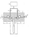
- the device for gas separation consists of a separation chamber 1, through which a shallow tunnel 2 extends for the passage of a flat strip-shaped substrate 3.
- two deflecting devices 4, 4 ' arranged at a distance from one another are provided in the tunnel. These deflection devices 4, 4 'are designed as rollers which extend over the entire width of the substrates 3.
- the tunnel 2 consists of a rectilinear inner tunnel section 5 between the deflecting devices 4, 4 'and respectively adjoining outer tunnel sections 6, 6'.
- the outer tunnel sections 6, 6 ' are angled slightly upwards relative to the inner tunnel section 5, for example at an angle of approximately 5 °. In conjunction with unwinding and winding devices for the strip-shaped substrate 3, not shown, this can be stretched over the deflection devices 4, 4 '.
- the tunnel 2 can in particular be located between the deflection devices 4, 4 'enclose this particularly tight. That is, the gap 7, 7 'between the substrate 3 and the tunnel wall can be designed to be particularly narrow, without damaging the substrate 3 would have to be feared.
- the deflecting devices 4, 4 ' are guided laterally in the wall of the tunnel 2 in roller receivers 8, 8' in such a way that the deflecting devices 4, 4 'protrude slightly into the tunnel 2 and in connection with the resting substrate 3 on the tunnel 2 a substrate side seal. If now the gap 7 is designed to be particularly narrow on the opposite side of the substrate 3, this leads to a particularly high increase in the flow resistance in the tunnel 2.
- gas flow 13 in the inner tunnel section 5 a directed from the gas inlets 9, 9 'to the central suction port 10 gas flow 13 can be realized, with their help in connection with the described increase in the flow resistance in the tunnel 2, the desired good gas separation between the tunnel inlet and outlet 14, 15 is achieved by the recessed gas is removed through the suction port 10 again.
- the gas flow 13 generated thereby prevents or minimizes the unwanted flow of another gas in the opposite direction.
- the separation chamber 1 according to the invention is particularly suitable for the gas-tight separation of different process areas of vacuum coating installations which operate in continuous operation.
- adjacent CVD deposition chambers for the coating of strip-shaped substrates 3 with amorphous silicon of different doping and in particular with low doping can be interconnected without mixing.
Landscapes
- Chemical & Material Sciences (AREA)
- Engineering & Computer Science (AREA)
- Mechanical Engineering (AREA)
- General Engineering & Computer Science (AREA)
- General Chemical & Material Sciences (AREA)
- Chemical Kinetics & Catalysis (AREA)
- Materials Engineering (AREA)
- Metallurgy (AREA)
- Organic Chemistry (AREA)
- Inorganic Chemistry (AREA)
- Chemical Vapour Deposition (AREA)
Description
- Die Erfindung betrifft eine Anordnung zur Gasseparation für Vakuumbeschichtungsanlagen mit mehreren Prozessbereichen, insbesondere bei CVD-Anlagen zur Beschichtung und Dotierung von flachen und/oder bandförmigen Substraten, mit einem das Substrat umschließenden und durch eine Separationskammer verlaufenden flachen Tunnel, in dem zwei Umlenkeinrichtungen zur Führung des Substrates in einem vorgegebenen Abstand zueinander angeordnet sind, derart, dass die Umlenkeinrichtungen den Querschnitt des Tunnels einengen, wobei der Tunnel mit Gaszu- und -ableitungen versehen ist.
- Bei der Bearbeitung von flachen und/oder bandförmigen Substraten, die gewöhnlich von Rolle-zu-Rolle erfolgt, müssen oft unterschiedliche Bearbeitungskammern durchlaufen werden, in denen unterschiedliche Prozessgase eingesetzt werden. Dabei kommt es darauf an, eine gute Trennung der Bearbeitungskammern voneinander zu gewährleisten, um ein Verschleppen der Prozessgase zu verhindern, was insbesondere bei stark toxischen Gasen besonders wichtig ist, oder auch dann notwendig ist, wenn Gase mit geringem Anteil an Dotanden eingesetzt werden. Im letzteren Fall muss dafür Sorgt getragen werden, dass überhaupt keine Gasvermischung bzw. Gasverschleppung eintreten kann.
- Oft werden dazu Gasvorhänge oder Gasschleusen am Anfang und Ende einer Prozesstrecke verwendet. In der
WO 2008/085604 A2 werden beispielsweise derartige Gasschleusen für Rolle-zu-Rölle Systeme beschrieben. Wesentliches Element ist hier ein Segment mit geringem Volumen zwischen zwei benachbarten Kammern mit größerem Volumen. Mittig in das Segment mit geringem Volumen wird Stickstoff eingebracht, so dass dieser in Richtung der beiden anderen Kammern strömt. Eine Vermischung der Gase in den beiden benachbarten Kammern wird somit verhindert. - Eine solche Gasseparation ist jedoch bei der CVD-Abscheidung auf einem bandförmigen Material mit amorphem Silizium in verschiedener Dotierung in insgesamt drei aufeinander folgenden Prozessschritten nicht ausreichend. Der geringe Anteil der jeweils eingesetzten Dotanden in den einzelnen Prozessbereichen führt zu besonders hohen Anforderungen an die Separierung der einzelnen Prozessschritte voneinander.
- Die
US 4 723 507 A offenbart eine Plasmabearbeitungskammer mit Spülgaszuführungen, einer Wasserstoffzuführung sowie einem zugehörigen Gasauslass und einen Kathodenschirm zwischen zwei Umlenkrollen für ein bandförmiges Substrat. Das bandförmige Substrat wird dabei an den Umlenkrollen vorbei durch einen Tunnel geführt, der zwischen den beiden Umlenkrollen mit einer Wasserstoff-Plasma-Kammer versehen ist. Mit einer Spülgaszuführung unter einer der Umlenkrollen soll das Eindringen eines Dotanden aus einer nachgeordneten Dotierkammer in die Wasserstoff-Plasma-Einrichtung verhindert werden. Mit einer weiteren Spülgaszuführung oberhalb des bandförmigen Substrates soll das Eindringen von Kontaminationen in den oberen Durchgang verhindern. - Die
US 5 919 310 A betrifft eine Anordnung mit einer Gasschleuse und Rollen zur Führung eines Substratbandes durch einen Kanal, der mittig zwischen den Rollen mit einem schlitzförmigen Gasvorhang versehen ist. - Aus der
US 5 130 170 A geht eine PVD-Anlage mit einer oder mehreren PVD-Vorrichtungen mit Umlenkrollen für das zu beschichtende Band hervor, die dieses um eine Trommel legen, sowie mit Gasschleusen beidseitig der PVD-Vorrichbung, die im Transportkanal für das Band Gasvorhänge ausbilden. - Schließlich geht aus der
CH 683 662 A3 - Der Erfindung liegt die Aufgabe zugrunde, eine Anordnung zur Gasseparation für Anlagen mit mehreren Prozessbereichen, insbesondere bei CVD-Anlagen zur Beschichtung und Dotierung von flachen und/oder bandförmigen Substraten mit amorphem Silizium zu schaffen, mit der eine besonders gute und sorgfältige Gasseparation gewährleistet wird.
- Die der Erfindung zugrunde liegende Aufgabe wird bei einer Anordnung der eingangs genannten Art dadurch gelöst, dass zwischen den Umlenkeinrichtungen und neben diesen jeweils ein Gaseinlass zwischen diesen mittig eine Saugöffnung zur Ausbildung einer von den Gaseinlässen zur mittigen Saugöffnung gerichteten Gasströmung angeordnet sind und wobei das Verhältnis der Leitwerte der jeweils äußeren Tunnelabschnitte zum Leitwert des inneren Tunnelabschnittes kleiner als 1:5 ist.
- Durch die Umlenkeinrichtungen wird einerseits ein störungsfreier Substratdurchlauf gewährleistet, so dass andererseits enge Spalte zwischen Substrat und dem Tunnel realisiert werden können.
- Weiterhin wird durch die definierte Auflage des Substrates auf den Umlenkeinrichtungen der Strömungswiderstand für vorbeiströmende Gase deutlich erhöht, so dass in Verbindung mit der zwischen den Umlenkeinrichtungen ausgebildeten Gasströmung zwischen dem Tunnelein- und -ausgang eine besonders gute Gasseparation erreicht wird.
- Besonders vorteilhaft ist es, wenn die Umlenkeinrichtungen aus sich über die gesamte Breite erstreckenden Rollen bestehen, die in Rollenaufnahmen neben dem Tunnel gelagert sind, derart, dass der Luftspalt zwischen dem Substrat und einer Tunnelwand auf einer Seite des Substrates durch die Rollenaufnahmen verläuft. Dadurch wird eine deutliche Erhöhung des Strömungswiderstandes erreicht.
- Der Tunnel zwischen den Umlenkrollen ist bevorzugt geradlinig ausgebildet und die sich an die Umlenkrollen anschließenden äußeren Tunnelabschnitte verlaufen gleichsinnig angewinkelt, z.B. in einem Winkel von ca. 5°, nach oben.
- In einer weiteren vorteilhaften Fortführung der Erfindung ist der Abstand der Wände des Tunnels, zumindest im geradlinigen Tunnelabschnitt zwischen den Umlenkrollen, auf wenige Millimeter reduziert.
- Um eine gute Regulierung der Gasströmung zwischen den Umlenkrollen zu gewährleisten, sind die Gaseinlässe mit Drosselventilen ausgestattet.
- In einer weiteren Fortführung der Erfindung ist die Länge der jeweiligen Tunnelabschnitte sehr viel größer, als die freie mittlere Weglänge des Gases bzw. Gasgemisches innerhalb des Tunnelbereiches.
- Die erfindungsgemäße Anordnung eignet sich besonders zur vermischungsfreien Verbindung benachbarter Prozessbereiche von Durchlauf-Prozessanlagen und insbesondere zur vermischungsfreien Verbindung von CVD-Abscheidekammern für die Beschichtung von bandförmigen Substraten mit amorphem Silizium unterschiedlicher Dotierung, insbesondere geringer Dotierung.
- Die Erfindung soll nachfolgend an einem Ausführungsbeispiel näher erläutert werden. Die zugehörige Zeichnungsfigur zeigt eine erfindungsgemäße Anordnung zur Gasseparation.
- Die Vorrichtung zur Gasseparation besteht aus einer Separationskammer 1, durch die sich ein flacher Tunnel 2 zur Durchführung eines flachen bandförmigen Substrates 3 erstreckt.
- Um eine gute Führung des flachen Substrates 3 im Tunnel 2 zu erreichen, sind zwei im Abstand zueinander angeordnete Umlenkeinrichtungen 4, 4' im Tunnel vorgesehen. Diese Umlenkeinrichtungen 4, 4' sind als Rollen ausgebildet, die sich über die gesamte Breite der Substrate 3 erstrecken.
- Wie aus der Zeichnungsfigur ersichtlich ist, besteht der Tunnel 2 aus einem geradlinigen inneren Tunnelabschnitt 5 zwischen den Umlenkeinrichtungen 4, 4' und sich jeweils anschließenden äußeren Tunnelabschnitten 6, 6'. Die äußeren Tunnelabschnitte 6, 6' sind gegenüber dem inneren Tunnelabschnitt 5 leicht nach oben angewinkelt, beispielsweise im Winkel von ca. 5°. In Verbindung mit nicht dargestellten Ab- und Aufwickeleinrichtungen für das bandförmige Substrat 3 lässt sich dieses über die Umlenkeinrichtungen 4, 4' spannen. Durch die damit straffe Führung des Substrates 3 kann der Tunnel 2 insbesondere zwischen den Umlenkeinrichtungen 4, 4' dieses besonders eng umschließen. D.h. der Spalt 7, 7' zwischen Substrat 3 und Tunnelwand kann besonders eng ausgelegt werden, ohne dass eine Beschädigung des Substrates 3 befürchtet werden müsste.
- Dadurch und in Verbindung mit der nachfolgend beschriebenen Maßnahme kann im Tunnel 2 ein besonders hoher Strömungswiderstand erreicht werden.
- Die Umlenkeinrichtungen 4, 4' sind seitlich in der Wand des Tunnels 2 in Rollenaufnahmen 8, 8' geführt und zwar derart, dass die Umlenkeinrichtungen 4, 4' etwas in den Tunnel 2 hineinragen und in Verbindung mit dem aufliegenden Substrat 3 den Tunnel 2 auf einer Substratseite abdichten. Wird nun der Spalt 7 auf der gegenüber liegenden Seite des Substrates 3 besonders eng ausgelegt, führt das zu einer besonders starken Vergrößerung des Strömungswiderstandes im Tunnel 2.
- Da damit allein noch keine ausreichende Separation erreichbar ist, sind im inneren Tunnelabschnitt 5 neben den Umlenkeinrichtungen 4, 4' Gaseinlässe 9, 9' vorgesehen und zwischen diesen eine Saugöffnung 10. Die Saugöffnung 10 ist mit einer nicht dargestellten Vakuumpumpe verbunden. Zusätzlich sind die Gaseinlässe 9, 9' über Drosselventile 11, 11' mit einem Vorratsbehälter 12 für ein Separationsgas, z.B. Wasserstoffgas, verbunden.
- Auf diese Weise kann im inneren Tunnelabschnitt 5 eine von den Gaseinlässen 9, 9' zur mittigen Saugöffnung 10 gerichtete Gasströmung 13 realisiert werden, mit deren Hilfe in Verbindung mit der beschriebenen Erhöhung des Strömungswiderstandes im Tunnel 2 die gewünschte gute Gasseparation zwischen Tunnelein- und -ausgang 14, 15 erreicht wird, indem das eingelassene Gas durch die Saugöffnung 10 wieder entfernt wird. Die damit erzeugte Gasströmung 13 verhindert bzw. minimiert die ungewollte Strömung eines anderen Gases in die Gegenrichtung.
- Durch geeignete Dimensionierung der Strömungsleitwerte in den Bereichen zwischen Gaseinlass 9, 9' und der Außenseite der Separationskammer 1, als auch zwischen Gaseinlass und mittiger Abpumpung kann ferner die Gasein- bzw. -ausströmung in den benachbarten Prozessbereich derart eingestellt werden, dass diese keine Störgröße für den dort stattfindenden Prozess darstellt. Weiterhin muss die Länge der jeweiligen Tunnelabschnitte sehr viel größer sein, als die freie Weglänge der im Tunnel 2 befindlichen Gase.
- Die erfindungsgemäße Separationskammer 1 ist zur gasdichten Trennung von unterschiedlichen Prozessbereichen von Vakuumbeschichtungsanlagen, welche im Durchlaufbetrieb arbeiten, besonders geeignet.
- Insbesondere können benachbarte CVD-Abscheidekammern für die Beschichtung von bandförmigen Substraten 3 mit amorphem Silizium unterschiedlicher Dotierung und insbesondere mit geringer Dotierung vermischungsfrei miteinander verbunden werden.
-
- 1
- Separationskammer
- 2
- Tunnel
- 3
- Substrat
- 4, 4'
- Umlenkeinrichtung
- 5
- innerer Tunnelabschnitt
- 6, 6'
- äußerer Tunnelabschnitt
- 7, 7'
- Spalt
- 8, 8'
- Rollenaufnahme
- 9, 9'
- Gaseinlass
- 10
- Saugöffnung
- 11
- Drosselventil
- 12
- Vorratsbehälter
- 13
- Gasströmung
- 14
- Tunneleingang
- 15
- Tunnelausgang
Claims (10)
- Anordnung zur Gasseparation für Vakuumbeschichtungsanlagen mit mehreren Prozessbereichen, insbesondere bei CVD-Anlagen zur Beschichtung und Dotierung von flachen und/oder bandförmigen Substraten, mit einem das Substrat umschließenden und durch eine Separationskammer verlaufenden flachen Tunnel, in dem zwei Umlenkeinrichtungen zur Führung des Substrates in einem vorgegebenen Abstand zueinander angeordnet sind, derart, dass die Umlenkeinrichtungen den Querschnitt des Tunnels einengen, wobei der Tunnel mit Gaszu- und -ableitungen versehen ist, dadurch gekennzeichnet, dass zwischen den Umlenkeinrichtungen (4, 4') und neben diesen jeweils ein Gaseinlass (9, 9') zwischen diesen mittig eine Saugöffnung (10) zur Ausbildung einer von den Gaseinlässen zur mittigen Saugöffnung gerichteten Gasströmung (13) angeordnet sind und wobei das Verhältnis der Leitwerte der jeweils äußeren Tunnelabschnitte zum Leitwert des inneren Tunnelanschnitts kleiner als 1:5 ist.
- Anordnung nach Anspruch 1, dadurch gekennzeichnet, dass die Umlenkeinrichtungen (4, 4') aus sich über die gesamte Breite des Substrates (3) erstreckenden Rollen bestehen, die in Rollenaufnahmen (8, 8') neben dem Tunnel (2) gelagert sind, derart, dass der Luftspalt zwischen dem Substrat (3) und einer Tunnelwand auf einer Seite des Substrates (3) durch die Rollenaüfnahme (8, 8') verläuft.
- Anordnung nach Anspruch 1 und 2, dadurch gekennzeichnet, dass der Tunnel (2) zwischen den Umlenkeinrichtungen (4, 4') geradlinig ausgebildet ist und dass die sich an die Umlenkrolleneinrichtungen (4, 4') anschließenden äußeren Tunnelabschnitte (6, 6') gleichsinnig angewinkelt verlaufen.
- Anordnung nach Anspruch 3, dadurch gekennzeichnet, dass der Winkel zwischen dem geradlinigen und den angewinkelten Tunnelabschnitten ca. 5° beträgt.
- Anordnung nach einem der Ansprüche 1 bis 3, dadurch gekennzeichnet, dass der Abstand der Wände des Tunnels (2), zumindest im geradlinigen inneren Tunnelabschnitt (5) zwischen den Umlenkeinrichtungen (4, 4'), auf wenige Millimeter reduziert ist.
- Anordnung nach Anspruch 5, dadurch gekennzeichnet, dass der Abstand ca. 1 mm beträgt.
- Anordnung nach Anspruch 1, dadurch gekennzeichnet, dass die Gaseinlässe (9, 9') mit Drosselventilen (11, 11') ausgestattet sind.
- Anordnung nach Anspruch 1, dadurch gekennzeichnet, dass die Länge der jeweiligen Tunnelabschnitte (5, 6, 6') sehr viel größer ist, als die freie mittlere Weglänge des Gases bzw. Gasgemisches innerhalb des Tunnelabschnittes (5, 6, 6')
- Verwendung der Anordnung zur Gasseparation nach den Ansprüchen 1 bis 8 zur vermischungsfreien Verbindung benachbarter Prozessbereiche von Durchlauf-Prozessanlagen.
- Verwendung der Anordnung zur Gasseparation nach den Ansprüchen 1 bis 8 zur vermischungsfreien Verbindung von CVD-Abscheidekammern für die Beschichtung von bandförmigen Substraten mit amorphem Silizium unterschiedlicher Dotierung.
Applications Claiming Priority (1)
| Application Number | Priority Date | Filing Date | Title |
|---|---|---|---|
| DE200910049570 DE102009049570B3 (de) | 2009-10-15 | 2009-10-15 | Anordnung zur Gasseparation und deren Verwendung |
Publications (2)
| Publication Number | Publication Date |
|---|---|
| EP2312014A1 EP2312014A1 (de) | 2011-04-20 |
| EP2312014B1 true EP2312014B1 (de) | 2015-05-27 |
Family
ID=43448506
Family Applications (1)
| Application Number | Title | Priority Date | Filing Date |
|---|---|---|---|
| EP10187390.9A Active EP2312014B1 (de) | 2009-10-15 | 2010-10-13 | Anordnung zur Gasseparation und deren Verwendung |
Country Status (3)
| Country | Link |
|---|---|
| EP (1) | EP2312014B1 (de) |
| DE (1) | DE102009049570B3 (de) |
| ES (1) | ES2546077T3 (de) |
Families Citing this family (2)
| Publication number | Priority date | Publication date | Assignee | Title |
|---|---|---|---|---|
| DE102013209047A1 (de) | 2013-05-15 | 2014-11-20 | Von Ardenne Gmbh | Vorrichtung zur Gasseparation in Vakuumbehandlungsanlagen bandförmiger Substrate |
| DE102016114395B4 (de) * | 2016-08-03 | 2022-03-10 | Solayer Gmbh | Gasseparationseinheit und Vakuumanlage mit einer solchen Einheit, Verfahren zu deren Betrieb |
Family Cites Families (4)
| Publication number | Priority date | Publication date | Assignee | Title |
|---|---|---|---|---|
| US4723507A (en) * | 1986-01-16 | 1988-02-09 | Energy Conversion Devices, Inc. | Isolation passageway including annular region |
| US5130170A (en) * | 1989-06-28 | 1992-07-14 | Canon Kabushiki Kaisha | Microwave pcvd method for continuously forming a large area functional deposited film using a curved moving substrate web with microwave energy with a directivity in one direction perpendicular to the direction of microwave propagation |
| US5919310A (en) * | 1991-10-07 | 1999-07-06 | Canon Kabushiki Kaisha | Continuously film-forming apparatus provided with improved gas gate means |
| JP2010509779A (ja) * | 2006-11-10 | 2010-03-25 | ソロパワー、インコーポレイテッド | 太陽電池吸収体を形成するための前駆体膜のオープンリール式反応 |
-
2009
- 2009-10-15 DE DE200910049570 patent/DE102009049570B3/de not_active Expired - Fee Related
-
2010
- 2010-10-13 EP EP10187390.9A patent/EP2312014B1/de active Active
- 2010-10-13 ES ES10187390.9T patent/ES2546077T3/es active Active
Also Published As
| Publication number | Publication date |
|---|---|
| DE102009049570B3 (de) | 2011-02-17 |
| EP2312014A1 (de) | 2011-04-20 |
| ES2546077T3 (es) | 2015-09-18 |
Similar Documents
| Publication | Publication Date | Title |
|---|---|---|
| DE4412541A1 (de) | Gaseinlassanordnung | |
| EP0307539A2 (de) | Verfahren und Vorrichtung zum Beschichten von Substraten | |
| EP2376670A1 (de) | Vakuumbeschichtungsanlage und verfahren zum betrieb einer vakuumbeschichtungsanlage | |
| AT516668B1 (de) | Vorrichtung und Verfahren zur Behandlung von flachem zu behandelndem Material | |
| EP3788180A2 (de) | Vorrichtung zum beschichten eines substrates mit einer kohlenstoffhaltigen beschichtung | |
| DE102011075851B4 (de) | Verfahren zur stabilen reaktiven Abscheidung von Oxiden von einer Rohrmagnetronanordnung in Vakuumbeschichtungsanlagen und Anordnung zur Durchführung des Verfahrens | |
| DE102009049570B3 (de) | Anordnung zur Gasseparation und deren Verwendung | |
| DE102012202715B4 (de) | Vakuumprozessanlage mit einer Einrichtung zur Druckseparation | |
| EP1704759B1 (de) | Düsenanordnung und verfahren zur behandlung eines behandlungsgutes mit einem behandlungsmedium | |
| DE102014018165B3 (de) | Lötvorrichtung mit Gasverteilung | |
| DE102005024180B4 (de) | Transferkammer und Vakuumbeschichtungsanlage | |
| DE102011076267B3 (de) | Verfahren und Anordnung zur Gasführung in Magnetron-Vakuumbeschichtungsanlagen | |
| DE102008026000B4 (de) | Verfahren und Vorrichtung zur Beschichtung flächiger Substrate | |
| EP3256618B1 (de) | Verfahren zum betrieb einer inline-beschichtungsanlage und inline-beschichtungsanlage | |
| DE102008017492B4 (de) | Verfahren zum Transport eines bandförmigen Substrats und Vakuumbeschichtungsanlage | |
| EP1475458B1 (de) | Vorrichtung zum Beschichten eines Substrats. | |
| WO2012175331A1 (de) | Verfahren zur bearbeitung von substraten und vorrichtung dazu | |
| DE102014101956A1 (de) | Vakuumkammeranordnung und Verfahren | |
| WO2006136187A1 (de) | Vorrichtung für die sukzessive beschichtung mehrerer substrate | |
| DE102009052873B4 (de) | Vorrichtung zum kontinuierlichen bewegten Einschleusen eines Bandsubstrats ins Hochvakuum | |
| DE102015114187B4 (de) | Durchlauf-Folienbehandlungsanlage vertikal ausgerichteter Substrate | |
| DE102016106441A1 (de) | Absaughaube in einem CVD-Reaktor | |
| EP3591088B1 (de) | Vorrichtung zum schmelztauchbeschichten eines metallbandes | |
| DE102014103877B4 (de) | Transportsystem und Vakuumkammer | |
| WO2019233703A1 (de) | Plasmabehandlungsvorrichtung mit einer linearen mikrowellen-plasmaquelle und einer gasleitvorrichtung |
Legal Events
| Date | Code | Title | Description |
|---|---|---|---|
| PUAI | Public reference made under article 153(3) epc to a published international application that has entered the european phase |
Free format text: ORIGINAL CODE: 0009012 |
|
| AK | Designated contracting states |
Kind code of ref document: A1 Designated state(s): AL AT BE BG CH CY CZ DE DK EE ES FI FR GB GR HR HU IE IS IT LI LT LU LV MC MK MT NL NO PL PT RO RS SE SI SK SM TR |
|
| AX | Request for extension of the european patent |
Extension state: BA ME |
|
| 17P | Request for examination filed |
Effective date: 20111020 |
|
| RIC1 | Information provided on ipc code assigned before grant |
Ipc: F16J 15/16 20060101ALI20141008BHEP Ipc: C23C 16/44 20060101ALI20141008BHEP Ipc: F16J 15/40 20060101ALI20141008BHEP Ipc: B01J 3/02 20060101ALI20141008BHEP Ipc: C23C 16/24 20060101AFI20141008BHEP Ipc: C23C 16/54 20060101ALI20141008BHEP |
|
| GRAP | Despatch of communication of intention to grant a patent |
Free format text: ORIGINAL CODE: EPIDOSNIGR1 |
|
| INTG | Intention to grant announced |
Effective date: 20141117 |
|
| GRAP | Despatch of communication of intention to grant a patent |
Free format text: ORIGINAL CODE: EPIDOSNIGR1 |
|
| INTG | Intention to grant announced |
Effective date: 20150316 |
|
| GRAS | Grant fee paid |
Free format text: ORIGINAL CODE: EPIDOSNIGR3 |
|
| GRAA | (expected) grant |
Free format text: ORIGINAL CODE: 0009210 |
|
| AK | Designated contracting states |
Kind code of ref document: B1 Designated state(s): AL AT BE BG CH CY CZ DE DK EE ES FI FR GB GR HR HU IE IS IT LI LT LU LV MC MK MT NL NO PL PT RO RS SE SI SK SM TR |
|
| REG | Reference to a national code |
Ref country code: GB Ref legal event code: FG4D Free format text: NOT ENGLISH |
|
| REG | Reference to a national code |
Ref country code: CH Ref legal event code: EP |
|
| REG | Reference to a national code |
Ref country code: AT Ref legal event code: REF Ref document number: 728924 Country of ref document: AT Kind code of ref document: T Effective date: 20150615 |
|
| REG | Reference to a national code |
Ref country code: IE Ref legal event code: FG4D Free format text: LANGUAGE OF EP DOCUMENT: GERMAN |
|
| REG | Reference to a national code |
Ref country code: DE Ref legal event code: R096 Ref document number: 502010009582 Country of ref document: DE |
|
| REG | Reference to a national code |
Ref country code: ES Ref legal event code: FG2A Ref document number: 2546077 Country of ref document: ES Kind code of ref document: T3 Effective date: 20150918 |
|
| REG | Reference to a national code |
Ref country code: LT Ref legal event code: MG4D |
|
| PG25 | Lapsed in a contracting state [announced via postgrant information from national office to epo] |
Ref country code: HR Free format text: LAPSE BECAUSE OF FAILURE TO SUBMIT A TRANSLATION OF THE DESCRIPTION OR TO PAY THE FEE WITHIN THE PRESCRIBED TIME-LIMIT Effective date: 20150527 Ref country code: FI Free format text: LAPSE BECAUSE OF FAILURE TO SUBMIT A TRANSLATION OF THE DESCRIPTION OR TO PAY THE FEE WITHIN THE PRESCRIBED TIME-LIMIT Effective date: 20150527 Ref country code: PT Free format text: LAPSE BECAUSE OF FAILURE TO SUBMIT A TRANSLATION OF THE DESCRIPTION OR TO PAY THE FEE WITHIN THE PRESCRIBED TIME-LIMIT Effective date: 20150928 Ref country code: NO Free format text: LAPSE BECAUSE OF FAILURE TO SUBMIT A TRANSLATION OF THE DESCRIPTION OR TO PAY THE FEE WITHIN THE PRESCRIBED TIME-LIMIT Effective date: 20150827 Ref country code: LT Free format text: LAPSE BECAUSE OF FAILURE TO SUBMIT A TRANSLATION OF THE DESCRIPTION OR TO PAY THE FEE WITHIN THE PRESCRIBED TIME-LIMIT Effective date: 20150527 |
|
| REG | Reference to a national code |
Ref country code: NL Ref legal event code: MP Effective date: 20150527 |
|
| PG25 | Lapsed in a contracting state [announced via postgrant information from national office to epo] |
Ref country code: BG Free format text: LAPSE BECAUSE OF FAILURE TO SUBMIT A TRANSLATION OF THE DESCRIPTION OR TO PAY THE FEE WITHIN THE PRESCRIBED TIME-LIMIT Effective date: 20150827 Ref country code: RS Free format text: LAPSE BECAUSE OF FAILURE TO SUBMIT A TRANSLATION OF THE DESCRIPTION OR TO PAY THE FEE WITHIN THE PRESCRIBED TIME-LIMIT Effective date: 20150527 Ref country code: LV Free format text: LAPSE BECAUSE OF FAILURE TO SUBMIT A TRANSLATION OF THE DESCRIPTION OR TO PAY THE FEE WITHIN THE PRESCRIBED TIME-LIMIT Effective date: 20150527 Ref country code: IS Free format text: LAPSE BECAUSE OF FAILURE TO SUBMIT A TRANSLATION OF THE DESCRIPTION OR TO PAY THE FEE WITHIN THE PRESCRIBED TIME-LIMIT Effective date: 20150927 Ref country code: GR Free format text: LAPSE BECAUSE OF FAILURE TO SUBMIT A TRANSLATION OF THE DESCRIPTION OR TO PAY THE FEE WITHIN THE PRESCRIBED TIME-LIMIT Effective date: 20150828 |
|
| PG25 | Lapsed in a contracting state [announced via postgrant information from national office to epo] |
Ref country code: DK Free format text: LAPSE BECAUSE OF FAILURE TO SUBMIT A TRANSLATION OF THE DESCRIPTION OR TO PAY THE FEE WITHIN THE PRESCRIBED TIME-LIMIT Effective date: 20150527 Ref country code: EE Free format text: LAPSE BECAUSE OF FAILURE TO SUBMIT A TRANSLATION OF THE DESCRIPTION OR TO PAY THE FEE WITHIN THE PRESCRIBED TIME-LIMIT Effective date: 20150527 |
|
| PG25 | Lapsed in a contracting state [announced via postgrant information from national office to epo] |
Ref country code: CZ Free format text: LAPSE BECAUSE OF FAILURE TO SUBMIT A TRANSLATION OF THE DESCRIPTION OR TO PAY THE FEE WITHIN THE PRESCRIBED TIME-LIMIT Effective date: 20150527 Ref country code: PL Free format text: LAPSE BECAUSE OF FAILURE TO SUBMIT A TRANSLATION OF THE DESCRIPTION OR TO PAY THE FEE WITHIN THE PRESCRIBED TIME-LIMIT Effective date: 20150527 Ref country code: SK Free format text: LAPSE BECAUSE OF FAILURE TO SUBMIT A TRANSLATION OF THE DESCRIPTION OR TO PAY THE FEE WITHIN THE PRESCRIBED TIME-LIMIT Effective date: 20150527 Ref country code: RO Free format text: LAPSE BECAUSE OF NON-PAYMENT OF DUE FEES Effective date: 20150527 |
|
| REG | Reference to a national code |
Ref country code: DE Ref legal event code: R097 Ref document number: 502010009582 Country of ref document: DE |
|
| PLBE | No opposition filed within time limit |
Free format text: ORIGINAL CODE: 0009261 |
|
| STAA | Information on the status of an ep patent application or granted ep patent |
Free format text: STATUS: NO OPPOSITION FILED WITHIN TIME LIMIT |
|
| PG25 | Lapsed in a contracting state [announced via postgrant information from national office to epo] |
Ref country code: IT Free format text: LAPSE BECAUSE OF FAILURE TO SUBMIT A TRANSLATION OF THE DESCRIPTION OR TO PAY THE FEE WITHIN THE PRESCRIBED TIME-LIMIT Effective date: 20150527 |
|
| 26N | No opposition filed |
Effective date: 20160301 |
|
| PG25 | Lapsed in a contracting state [announced via postgrant information from national office to epo] |
Ref country code: LU Free format text: LAPSE BECAUSE OF FAILURE TO SUBMIT A TRANSLATION OF THE DESCRIPTION OR TO PAY THE FEE WITHIN THE PRESCRIBED TIME-LIMIT Effective date: 20151013 Ref country code: SI Free format text: LAPSE BECAUSE OF FAILURE TO SUBMIT A TRANSLATION OF THE DESCRIPTION OR TO PAY THE FEE WITHIN THE PRESCRIBED TIME-LIMIT Effective date: 20150527 |
|
| REG | Reference to a national code |
Ref country code: CH Ref legal event code: PL |
|
| GBPC | Gb: european patent ceased through non-payment of renewal fee |
Effective date: 20151013 |
|
| PG25 | Lapsed in a contracting state [announced via postgrant information from national office to epo] |
Ref country code: MC Free format text: LAPSE BECAUSE OF FAILURE TO SUBMIT A TRANSLATION OF THE DESCRIPTION OR TO PAY THE FEE WITHIN THE PRESCRIBED TIME-LIMIT Effective date: 20150527 |
|
| REG | Reference to a national code |
Ref country code: IE Ref legal event code: MM4A |
|
| PG25 | Lapsed in a contracting state [announced via postgrant information from national office to epo] |
Ref country code: LI Free format text: LAPSE BECAUSE OF NON-PAYMENT OF DUE FEES Effective date: 20151031 Ref country code: CH Free format text: LAPSE BECAUSE OF NON-PAYMENT OF DUE FEES Effective date: 20151031 Ref country code: GB Free format text: LAPSE BECAUSE OF NON-PAYMENT OF DUE FEES Effective date: 20151013 |
|
| REG | Reference to a national code |
Ref country code: FR Ref legal event code: ST Effective date: 20160630 |
|
| PG25 | Lapsed in a contracting state [announced via postgrant information from national office to epo] |
Ref country code: FR Free format text: LAPSE BECAUSE OF NON-PAYMENT OF DUE FEES Effective date: 20151102 |
|
| PG25 | Lapsed in a contracting state [announced via postgrant information from national office to epo] |
Ref country code: IE Free format text: LAPSE BECAUSE OF NON-PAYMENT OF DUE FEES Effective date: 20151013 |
|
| REG | Reference to a national code |
Ref country code: AT Ref legal event code: MM01 Ref document number: 728924 Country of ref document: AT Kind code of ref document: T Effective date: 20151013 |
|
| PG25 | Lapsed in a contracting state [announced via postgrant information from national office to epo] |
Ref country code: AT Free format text: LAPSE BECAUSE OF NON-PAYMENT OF DUE FEES Effective date: 20151013 |
|
| PGFP | Annual fee paid to national office [announced via postgrant information from national office to epo] |
Ref country code: ES Payment date: 20161025 Year of fee payment: 7 |
|
| PG25 | Lapsed in a contracting state [announced via postgrant information from national office to epo] |
Ref country code: SM Free format text: LAPSE BECAUSE OF FAILURE TO SUBMIT A TRANSLATION OF THE DESCRIPTION OR TO PAY THE FEE WITHIN THE PRESCRIBED TIME-LIMIT Effective date: 20150527 Ref country code: HU Free format text: LAPSE BECAUSE OF FAILURE TO SUBMIT A TRANSLATION OF THE DESCRIPTION OR TO PAY THE FEE WITHIN THE PRESCRIBED TIME-LIMIT; INVALID AB INITIO Effective date: 20101013 |
|
| PG25 | Lapsed in a contracting state [announced via postgrant information from national office to epo] |
Ref country code: SE Free format text: LAPSE BECAUSE OF FAILURE TO SUBMIT A TRANSLATION OF THE DESCRIPTION OR TO PAY THE FEE WITHIN THE PRESCRIBED TIME-LIMIT Effective date: 20150527 Ref country code: CY Free format text: LAPSE BECAUSE OF FAILURE TO SUBMIT A TRANSLATION OF THE DESCRIPTION OR TO PAY THE FEE WITHIN THE PRESCRIBED TIME-LIMIT Effective date: 20150527 Ref country code: NL Free format text: LAPSE BECAUSE OF FAILURE TO SUBMIT A TRANSLATION OF THE DESCRIPTION OR TO PAY THE FEE WITHIN THE PRESCRIBED TIME-LIMIT Effective date: 20150527 |
|
| PG25 | Lapsed in a contracting state [announced via postgrant information from national office to epo] |
Ref country code: BE Free format text: LAPSE BECAUSE OF NON-PAYMENT OF DUE FEES Effective date: 20151031 |
|
| PG25 | Lapsed in a contracting state [announced via postgrant information from national office to epo] |
Ref country code: MT Free format text: LAPSE BECAUSE OF FAILURE TO SUBMIT A TRANSLATION OF THE DESCRIPTION OR TO PAY THE FEE WITHIN THE PRESCRIBED TIME-LIMIT Effective date: 20150527 Ref country code: TR Free format text: LAPSE BECAUSE OF FAILURE TO SUBMIT A TRANSLATION OF THE DESCRIPTION OR TO PAY THE FEE WITHIN THE PRESCRIBED TIME-LIMIT Effective date: 20150527 |
|
| PG25 | Lapsed in a contracting state [announced via postgrant information from national office to epo] |
Ref country code: MK Free format text: LAPSE BECAUSE OF FAILURE TO SUBMIT A TRANSLATION OF THE DESCRIPTION OR TO PAY THE FEE WITHIN THE PRESCRIBED TIME-LIMIT Effective date: 20150527 |
|
| PG25 | Lapsed in a contracting state [announced via postgrant information from national office to epo] |
Ref country code: AL Free format text: LAPSE BECAUSE OF FAILURE TO SUBMIT A TRANSLATION OF THE DESCRIPTION OR TO PAY THE FEE WITHIN THE PRESCRIBED TIME-LIMIT Effective date: 20150527 |
|
| REG | Reference to a national code |
Ref country code: ES Ref legal event code: FD2A Effective date: 20181220 |
|
| PG25 | Lapsed in a contracting state [announced via postgrant information from national office to epo] |
Ref country code: ES Free format text: LAPSE BECAUSE OF NON-PAYMENT OF DUE FEES Effective date: 20171014 |
|
| REG | Reference to a national code |
Ref country code: DE Ref legal event code: R082 Ref document number: 502010009582 Country of ref document: DE Representative=s name: PATENTANWALTSKANZLEI MEYER, DE Ref country code: DE Ref legal event code: R081 Ref document number: 502010009582 Country of ref document: DE Owner name: ASUS RESOURCES PTE. LTD., SG Free format text: FORMER OWNER: FHR ANLAGENBAU GMBH, 01458 OTTENDORF-OKRILLA, DE |
|
| PGFP | Annual fee paid to national office [announced via postgrant information from national office to epo] |
Ref country code: DE Payment date: 20251020 Year of fee payment: 16 |