EP2310638B1 - Alignment device for use with a tappet - Google Patents
Alignment device for use with a tappet Download PDFInfo
- Publication number
- EP2310638B1 EP2310638B1 EP09792252.0A EP09792252A EP2310638B1 EP 2310638 B1 EP2310638 B1 EP 2310638B1 EP 09792252 A EP09792252 A EP 09792252A EP 2310638 B1 EP2310638 B1 EP 2310638B1
- Authority
- EP
- European Patent Office
- Prior art keywords
- tappet
- alignment device
- opening
- stem portion
- height
- Prior art date
- Legal status (The legal status is an assumption and is not a legal conclusion. Google has not performed a legal analysis and makes no representation as to the accuracy of the status listed.)
- Not-in-force
Links
- 238000003780 insertion Methods 0.000 claims description 4
- 230000037431 insertion Effects 0.000 claims description 4
- 238000002485 combustion reaction Methods 0.000 description 7
- 230000008878 coupling Effects 0.000 description 5
- 238000010168 coupling process Methods 0.000 description 5
- 238000005859 coupling reaction Methods 0.000 description 5
- 230000002093 peripheral effect Effects 0.000 description 4
- 238000010276 construction Methods 0.000 description 2
- 239000012530 fluid Substances 0.000 description 2
- 238000003754 machining Methods 0.000 description 2
- 239000000853 adhesive Substances 0.000 description 1
- 230000001070 adhesive effect Effects 0.000 description 1
- 230000000712 assembly Effects 0.000 description 1
- 238000000429 assembly Methods 0.000 description 1
- 238000005452 bending Methods 0.000 description 1
- 239000000446 fuel Substances 0.000 description 1
- 238000007373 indentation Methods 0.000 description 1
- 238000002955 isolation Methods 0.000 description 1
- 238000004519 manufacturing process Methods 0.000 description 1
- 238000012986 modification Methods 0.000 description 1
- 230000004048 modification Effects 0.000 description 1
- 239000003921 oil Substances 0.000 description 1
- 238000010008 shearing Methods 0.000 description 1
- 230000007704 transition Effects 0.000 description 1
- XLYOFNOQVPJJNP-UHFFFAOYSA-N water Substances O XLYOFNOQVPJJNP-UHFFFAOYSA-N 0.000 description 1
Images


Classifications
-
- F—MECHANICAL ENGINEERING; LIGHTING; HEATING; WEAPONS; BLASTING
- F01—MACHINES OR ENGINES IN GENERAL; ENGINE PLANTS IN GENERAL; STEAM ENGINES
- F01L—CYCLICALLY OPERATING VALVES FOR MACHINES OR ENGINES
- F01L1/00—Valve-gear or valve arrangements, e.g. lift-valve gear
- F01L1/12—Transmitting gear between valve drive and valve
- F01L1/14—Tappets; Push rods
-
- F—MECHANICAL ENGINEERING; LIGHTING; HEATING; WEAPONS; BLASTING
- F01—MACHINES OR ENGINES IN GENERAL; ENGINE PLANTS IN GENERAL; STEAM ENGINES
- F01L—CYCLICALLY OPERATING VALVES FOR MACHINES OR ENGINES
- F01L1/00—Valve-gear or valve arrangements, e.g. lift-valve gear
- F01L1/12—Transmitting gear between valve drive and valve
- F01L1/14—Tappets; Push rods
- F01L1/143—Tappets; Push rods for use with overhead camshafts
-
- F—MECHANICAL ENGINEERING; LIGHTING; HEATING; WEAPONS; BLASTING
- F01—MACHINES OR ENGINES IN GENERAL; ENGINE PLANTS IN GENERAL; STEAM ENGINES
- F01L—CYCLICALLY OPERATING VALVES FOR MACHINES OR ENGINES
- F01L1/00—Valve-gear or valve arrangements, e.g. lift-valve gear
- F01L1/12—Transmitting gear between valve drive and valve
-
- F—MECHANICAL ENGINEERING; LIGHTING; HEATING; WEAPONS; BLASTING
- F01—MACHINES OR ENGINES IN GENERAL; ENGINE PLANTS IN GENERAL; STEAM ENGINES
- F01L—CYCLICALLY OPERATING VALVES FOR MACHINES OR ENGINES
- F01L1/00—Valve-gear or valve arrangements, e.g. lift-valve gear
- F01L1/12—Transmitting gear between valve drive and valve
- F01L1/14—Tappets; Push rods
- F01L1/146—Push-rods
-
- Y—GENERAL TAGGING OF NEW TECHNOLOGICAL DEVELOPMENTS; GENERAL TAGGING OF CROSS-SECTIONAL TECHNOLOGIES SPANNING OVER SEVERAL SECTIONS OF THE IPC; TECHNICAL SUBJECTS COVERED BY FORMER USPC CROSS-REFERENCE ART COLLECTIONS [XRACs] AND DIGESTS
- Y10—TECHNICAL SUBJECTS COVERED BY FORMER USPC
- Y10T—TECHNICAL SUBJECTS COVERED BY FORMER US CLASSIFICATION
- Y10T74/00—Machine element or mechanism
- Y10T74/21—Elements
- Y10T74/2101—Cams
- Y10T74/2107—Follower
Definitions
- the present invention relates to tappets and, more particularly, to alignment devices for use with tappets.
- Tappets are typically included in a valve train of an internal combustion engine to transmit motion from a cam shaft of the engine to one or more intake or exhaust valves. As the cam shaft rotates, the tappets receive both a sideways force and a downward force from the cam shaft, but only transmit the downward force to the valves to open and/or close the valves. The tappets thereby reduce the possibility of bending or otherwise damaging the valves during operation of the engine.
- DE 43 24 756 A1 relates to a locking device for a cam follower, preferably a bucket tappet, consisting of parts movable with respect to each other such as the bucket and the internal tappet.
- the locking device is inserted into a through hole and is arranged slidably within a guiding path of the cylinder head.
- the locking device is hereby inserted into the through hole from the inside having a slight clearance, wherein the locking device has different guiding lengths on the inside versus the outside.
- JP 02 118103 U discloses a locking device inserted into an aperture of a roller tappet for preventing a turning of the tappet.
- the locking device is formed by a stopper bolt having a stem portion and a head portion, wherein the bolt is inserted into the aperture of the tappet from the outside.
- the head portion is dimensioned such that it abuts the outer surface of the tappet when the bolt is arranged in a locking position.
- US2006/016406 A1 relates to a periodically actuable tappet for a valve train, said tappet comprising a hollow cylindrical skirt that can be arranged through an outer peripheral surface in a guide bore of a surrounding structure, said skirt comprising a window-type aperture in which a separate anti-rotation device is arranged through a radially inner portion, a radially outer portion of the anti-rotation device extending beyond the skirt for guidance in a longitudinal groove that intersects the guide bore, wherein the anti-rotation device, as viewed in cross-section, is substantially mushroom-shaped, the inner portion has a rectangular cross-section corresponding to a geometry of the aperture of the skirt, into which cross-section, the outer portion merges in the manner of a roof through a fractional cylindrical outer peripheral surface, inner legs of the outer portion extend beyond the aperture in peripheral direction and bear against the outer peripheral surface of the skirt.
- the invention provides a tappet movable along an axis.
- the tappet includes a skirt defining a generally cylindrical outer surface, an opening, and a flat formed in the outer surface adjacent the opening.
- the tappet further includes an alignment device positioned at least partially within the opening.
- the alignment device includes a stem portion, a head portion, and a lip formed between the stem portion and the head portion. The lip is engaged with the flat to provide a flat surface to flat surface engagement, thereby increasing an area of contact between the skirt and the alignment device.
- Figs. 1 and 2 illustrate a tappet 10 embodying the invention.
- the tappet 10 is configured for use in a valve train of an internal combustion engine to facilitate opening and closing an intake valve or an exhaust valve of the valve train.
- a cam shaft of the engine rotates, a portion of the cam shaft, or a rocker arm connected to the cam shaft, engages the tappet 10 to convert the rotational motion of the cam shaft into linear motion of the tappet 10.
- a valve head of the intake or exhaust valve is positioned within and connected to the tappet 10 such that, as the tappet 10 moves in a linear direction, the valve is opened and closed. Forces from the cam shaft are thereby transmitted through the tappet 10 to the valve such that only forces in substantially the same direction as the motion of the valve act on the valve.
- the tappet 10 serves as a torsional vibration isolation device between the cam shaft and the valve to inhibit rotational forces from being transmitted to the valve.
- the tappet 10 may additionally or alternatively be used in other types of assemblies where it is desirable to translate rotational motion of one component into linear motion of another component.
- the tappet 10 may be configured for use in a fluid pump to help drive a fluid (e.g., fuel, oil, water, or the like).
- the illustrated tappet 10 is a cup-shaped tappet and includes a skirt 14.
- the skirt 14 is generally cylindrical and defines an opening 18 for receiving an alignment device 22.
- the opening 18 is generally rectangular and is formed by, for example, piercing, machining, or otherwise cutting into the skirt 14.
- the opening 18 is also generally larger (e.g., wider) than the alignment device 22 to provide clearance for the alignment device 22 during assembly of the alignment device 22 and the tappet 10.
- providing a generally larger opening 18 increases tolerances while locating and machining the opening 18 in the skirt 14.
- the opening 18 may be another suitable shape for receiving a similarly shaped alignment device and/or the opening 18 may be relatively larger or smaller.
- the skirt 14 also defines two flats 26, 30, or indentations, formed on an outer surface 34 of the skirt 14 adjacent to the opening 18.
- the flats 26, 30 are positioned on opposite sides of the opening 18 (e.g., above and below on leading and trailing sides relative to the direction of reciprocation of the tappet 10).
- the flats 26, 30 are configured to receive portions of the alignment device 22 extending beyond a perimeter of the opening 18 to help position and secure the alignment device 22 within the opening 18.
- the flats 26, 30 also help control axis-to-axis position between the tappet 10 and the alignment device 22 such that a longitudinal axis of the alignment device 22 is generally parallel to and properly spaced from a longitudinal axis of the tappet 10.
- the illustrated flats 26, 30 have widths that are less than the width of the opening 18, but are generally the same width as the alignment device 22.
- a beveled edge 38, 42 is formed between each flat 26, 30 and the opening 18 to facilitate assembly (e.g., insertion) of the alignment device 22 into the opening 18.
- the tappet 10 is positioned within a guide bore 46 in, for example, a cylinder head 50 of an internal combustion engine.
- the tappet 10 moves (e.g., oscillates or reciprocates) within the guide bore 46 along a central axis 54 to transmit motion from a cam shaft of the internal combustion engine to a valve (e.g., an intake valve or an exhaust valve).
- the illustrated guide bore 46 defines a groove 58 extending along a portion of the length of the guide bore 46.
- the groove 58 receives a portion of the alignment device 22 to ensure proper alignment of the tappet 10 within the bore 46 during manufacture and assembly of the engine.
- the groove 58 and the alignment device 22 also cooperate to prevent rotation of the tappet 10 about the central axis 54 during operation of the internal combustion engine.
- Fig. 5 illustrates the alignment device 22 in more detail.
- the illustrated alignment device 22, or dowel pin includes a stem portion 62 and a head portion 66 integrally formed as a single piece. In other embodiments, the stem portion 62 and the head portion 66 may be separate pieces welded, glued, or otherwise fastened together.
- Each portion 62, 66 includes a generally planar first, or top, surface 70, 74 and a generally planar second, or bottom, surface 78, 82 ( Fig. 6 ).
- the stem portion 62 fits within the opening 18 in the skirt 14 to couple the dowel pin 22 to the skirt 14. As shown in Fig.
- the height of the stem portion 62 is substantially the same as the height of the opening 18 such that the stem portion 62 is held in place by an interference fit between the top and bottom surfaces 70, 78 of the stem portion 62 and an inner perimeter surface 86 ( Fig. 3 ) of the opening 18.
- the stem portion 62 may additionally be secured within the opening 18 of the skirt 14 using suitable coupling means (e.g., fasteners, adhesives, or the like).
- the head portion 66 extends outwardly from the skirt 14 and fits within the groove 58 formed in the guide bore 46 ( Fig. 4 ).
- a height H 1 of the head portion 66 of the dowel pin 22 is greater than a height H 2 of the stem portion 62 (as measured in the same direction as height H 1 ), forming an upper lip 90 between the top surfaces 70, 74 of the stem and head portions 62, 66 and a lower lip 94 between the bottom surfaces 78, 82 of the stem and head portions 62, 66.
- Each lip 90, 94 fits within one of the flats 26, 30 adjacent to the opening 18 to help position and secure the dowel pin 22 within the opening 18.
- the flats 26, 30 and the lips 90, 94 also provide a flat surface to flat surface engagement, increasing the area of contact between the skirt 14 and the dowel pin 22.
- the difference between the height H 1 of the head portion 66 and the height H 2 of the stem portion 62 is between about 0.5 mm and about 6.0 mm such that each lip 90, 94 is between about 0.25 mm and about 3.0 mm tall.
- the height H 1 of the head portion 66 is about 5.0 mm and the height H 2 of the stem portion 62 is about 4.0 mm such that the height difference is about 1.0 mm and each lip 90, 94 is about 0.5 mm tall.
- the dowel pin 22 has a generally T-shaped cross-sectional shape when viewed on its side (see Figs. 4 and 6 ) and taken through a plane substantially parallel to, or including, the central axis 54.
- the plane thereby extends in substantially the same direction as the direction of motion of the tappet 10.
- the central axis 54 extends in the vertical direction such that the plane is a substantially vertical plane.
- the tappet 10 may reciprocate at an angle (e.g., between about 1° and 179°) relative to vertical.
- the plane may also be angled relative to vertical so that the plane extends in substantially the same direction as the direction of motion of the tappet 10.
- the stem portion 62 and the head portion 66 have generally the same width such that the dowel pin 22 includes a curved side surface 98.
- the dowel pin 22 has a partially circular cross-sectional shape when taken through a plane 102 ( Fig. 6 ) substantially perpendicular to the central axis 54 (e.g., when viewed from the top or bottom).
- the plane 102 is a substantially horizontal plane, but may alternatively be angled relative to horizontal in embodiments where the tappet 10 reciprocates at an angle relative to vertical.
- the stem portion 62 includes a planar rear surface 106 such that the cross-sectional shape of the dowel pin 22 when taken through plane 102 is only a partial circle.
- the planar rear surface 106 minimizes the amount that the stem portion 62 extends into the tappet 10, providing clearance within a cavity 110 ( Fig. 4 ) of the skirt 14 for other components (e.g., a valve spring, a pump plunger, or a head of the intake or exhaust valve).
- the dowel pin 22 may have other suitable cross-sectional shapes when taken through the plane 102.
- the dowel pin 22 may have a fully circular (see Fig. 7 ), a rectangular, a square, or a hexagonal cross-sectional shape.
- the stem portion 62 includes an upper beveled edge 114 between the top surface 70 of the stem portion 62 and the rear surface 106.
- the stem portion 62 also includes a lower beveled edge 118 between the bottom surface 78 of the stem portion 62 and the rear surface 106.
- the beveled edges 114,118 of the stem portion 62 facilitate insertion of the stem portion 62 into the opening 18 in the skirt 14 during assembly of the tappet 10.
- the head portion 66 includes an upper beveled edge 122 between the top surface 74 of the head portion 66 and the curved side surface 98.
- the head portion 66 also includes a lower beveled edge 126 between the bottom surface 82 of the head portion 66 and the curved side surface 98.
- the beveled edges 122, 126 of the head portion 66 create a smoother transition between the top and bottom surfaces 74, 82 and the curved side surface 98, reducing the possibility of the dowel pin 22 catching or snagging on an imperfection (e.g., a protrusion) present on a surface of the guide bore 46 while the dowel pin 22 reciprocates within the guide bore 46.
- Fig. 7 illustrates another example of an alignment device 222 for use with the tappet 10. Similar to the alignment device 22 discussed above with reference to Figs. 5 and 6 , the illustrated alignment device 222, or dowel pin, includes a stem portion 262 and a head portion 266 integrally formed as a single piece. Each portion 262, 266 includes a generally planar top surface 270, 274 and a generally planar bottom surface. The stem portion 262 fits within the opening 18 in the skirt 14 to couple the dowel pin 222 to the skirt 14. The height of the stem portion 262 is substantially the same as the height of the opening 18 such that the stem portion 262 is held in place by an interference fit, but may additionally or alternatively be secured within the opening 18 using other suitable coupling means.
- the head portion 266 extends outwardly from the skirt 14 and fits within the groove 58 formed in the guide bore 46 ( Fig. 4 ).
- the height of the head portion 266 of the dowel pin 222 is greater than the height of the stem portion 262, forming an upper lip 290 between the top surfaces 270, 274 of the stem and head portions 262, 366 and a lower lip 294 between the bottom surfaces of the stem and head portions 262, 266.
- Each lip 290, 294 fits within one of the flats 26, 30 ( Fig. 3 ) adjacent to the opening 18 to help position and secure the dowel pin 222 in the opening 18.
- the height difference between the stem portion 262 and the head portion 266 causes the dowel pin 222 to have a generally T-shaped cross-sectional shape when taken through a plane substantially parallel to, or including, the central axis 54 ( Fig. 4 ).
- the widths of the stem portion 262 and the head portion 266 are equal such that the dowel pin 222 includes a continuous, curved side surface 298.
- the dowel pin 222 has a completely circular cross-sectional shape when taken through the plane 102 ( Fig. 6 ) substantially perpendicular to the central axis 54.
- Such a construction is feasible when space within the cavity 46 of the skirt 14 allows the dowel pin 222 to protrude deeper into the cavity 110.
- the illustrated head portion 266 includes an upper beveled edge 322 between the top surface 274 of the head portion 266 and the curved side surface 298.
- the head portion 266 also includes a lower beveled edge 326 between the bottom surface of the head portion 266 and the curved side surface 298.
- the stem portion 262 includes non-beveled edges 314, 318 between the top and bottom surfaces 270 and the curved side surface 298 of the stem portion 262.
- the stem portion 262 may include upper and lower beveled edges, similar to the dowel pin 22 discussed above.
- Fig. 8 illustrates a portion of another example of an alignment device 422 for use with the tappet 10.
- the illustrated alignment device 422, or dowel pin includes a stem portion 462 and a head portion 466 integrally formed as a single piece.
- Each portion 462, 466 includes a generally planar top surface 470, 474 and a generally planar bottom surface (not shown).
- the stem portion 462 fits within the opening 18 in the skirt 14 to couple the dowel pin 422 to the skirt 14.
- the height of the stem portion 462 is substantially the same as the height of the opening 18 such that the stem portion 462 is held in place by an interference fit, but may additionally or alternatively be secured within the opening 18 using other suitable coupling means.
- the head portion 466 extends outwardly from the skirt 14 and fits within the groove 58 formed in the guide bore 46 ( Fig. 4 ).
- the height of the head portion 466 of the dowel pin 422 is greater than the height of the stem portion 462, forming an upper lip 490 between the top surfaces 470, 474 of the stem and head portions 462, 466 and a lower lip (not shown) between the bottom surfaces of the stem and head portions 462, 466.
- Each lip 490 fits within one of the flats 26, 30 ( Fig. 3 ) adjacent to the opening 18 to help position and secure the dowel pin 422 in the opening 18.
- the illustrated dowel pin 422 also includes an undercut 496 formed adjacent to the upper lip 490.
- the undercut 496 provides additional clearance for the skirt 14 when the stem portion 462 is inserted into the opening 18.
- the dowel pin 422 may also include a second undercut formed adjacent to the bottom lip between the stem portion 462 and the head portion 466 in a manner similar to the illustrated undercut 496.
- the height difference between the stem portion 462 and the head portion 466 causes the dowel pin 422 to have a generally T-shaped cross-sectional shape when taken through the plane substantially parallel to, or including, the central axis 54 ( Fig. 4 ).
- the widths of the stem portion 462 and the head portion 466 are equal such that the dowel pin 422 includes a curved side surface 498.
- the stem portion 462 includes a planar rear surface 506 such that the dowel pin 422 has a partial circular cross-sectional shape when taken through the plane 102 ( Fig. 6 ) substantially perpendicular to the central axis 54, similar to the dowel pin 22 shown in Figs. 5 and 6 .
- the stem portion 462 includes an upper beveled edge 514 between the top surface 470 of the stem portion 462 and the rear surface 506.
- the head portion 466 also includes an upper beveled edge 522 between the top surface 474 of the head portion 466 and the curved side surface 498.
- the stem portion 462 and the head portion 466 may each include a lower beveled edge between the bottom surfaces and the rear surface 506 or the side surface 498, respectively.
Landscapes
- Engineering & Computer Science (AREA)
- Mechanical Engineering (AREA)
- General Engineering & Computer Science (AREA)
- Valve-Gear Or Valve Arrangements (AREA)
Description
- This applications claims priority to
U.S. Provisional Patent Application No. 61/094,225, filed September 4, 2008 - The present invention relates to tappets and, more particularly, to alignment devices for use with tappets.
- Tappets are typically included in a valve train of an internal combustion engine to transmit motion from a cam shaft of the engine to one or more intake or exhaust valves. As the cam shaft rotates, the tappets receive both a sideways force and a downward force from the cam shaft, but only transmit the downward force to the valves to open and/or close the valves. The tappets thereby reduce the possibility of bending or otherwise damaging the valves during operation of the engine.
-
DE 43 24 756 A1 relates to a locking device for a cam follower, preferably a bucket tappet, consisting of parts movable with respect to each other such as the bucket and the internal tappet. The locking device is inserted into a through hole and is arranged slidably within a guiding path of the cylinder head. The locking device is hereby inserted into the through hole from the inside having a slight clearance, wherein the locking device has different guiding lengths on the inside versus the outside. -
JP 02 118103 U -
US2006/016406 A1 relates to a periodically actuable tappet for a valve train, said tappet comprising a hollow cylindrical skirt that can be arranged through an outer peripheral surface in a guide bore of a surrounding structure, said skirt comprising a window-type aperture in which a separate anti-rotation device is arranged through a radially inner portion, a radially outer portion of the anti-rotation device extending beyond the skirt for guidance in a longitudinal groove that intersects the guide bore, wherein the anti-rotation device, as viewed in cross-section, is substantially mushroom-shaped, the inner portion has a rectangular cross-section corresponding to a geometry of the aperture of the skirt, into which cross-section, the outer portion merges in the manner of a roof through a fractional cylindrical outer peripheral surface, inner legs of the outer portion extend beyond the aperture in peripheral direction and bear against the outer peripheral surface of the skirt. - The underlying technical problem has been solved by the subject-matter of
independent claim 1. - In an example, the invention provides a tappet movable along an axis. The tappet includes a skirt defining a generally cylindrical outer surface, an opening, and a flat formed in the outer surface adjacent the opening. The tappet further includes an alignment device positioned at least partially within the opening. The alignment device includes a stem portion, a head portion, and a lip formed between the stem portion and the head portion. The lip is engaged with the flat to provide a flat surface to flat surface engagement, thereby increasing an area of contact between the skirt and the alignment device.
- Other aspects of the invention will become apparent by consideration of the detailed description and accompanying drawings.
-
-
Fig. 1 is a perspective view of a tappet including an alignment device according to one embodiment of the invention. -
Fig. 2 is an exploded perspective view of the tappet and the alignment device shown inFig. 1 . -
Fig. 3 is an enlarged exploded perspective view of a portion of the tappet and the alignment device shown inFig. 1 . -
Fig. 4 is a cross-sectional view of the tappet positioned within a guide bore of an internal combustion engine. -
Fig. 5 is an enlarged perspective view of the alignment device shown inFig. 1 . -
Fig. 6 is an enlarged cross-sectional view of the alignment device shown inFig. 5 coupled to the tappet. -
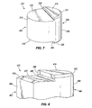
Fig. 7 is an enlarged perspective view of an alignment device according to another embodiment of the invention. -
Fig. 8 is an enlarged perspective view of a portion of an alignment device according to yet another embodiment of the invention. - Before any embodiments of the invention are explained in detail, it is to be understood that the invention is not limited in its application to the details of construction and the arrangement of components set forth in the following description or illustrated in the following drawings. The invention is capable of other embodiments and of being practiced or of being carried out in various ways. Also, it is to be understood that the phraseology and terminology used herein are for the purpose of description and should not be regarded as limiting. The use of "including," "comprising," or "having" and variations thereof herein is meant to encompass the items listed thereafter and equivalents thereof as well as additional items. Unless specified or limited otherwise, the terms "mounted," "connected," "supported," and "coupled" and variations thereof are used broadly and encompass both direct and indirect mountings, connections, supports, and couplings. Further, "connected" and "coupled" are not restricted to physical or mechanical connections or couplings. In addition, the terms "top," "bottom," "rear," "front," "vertical," "horizontal," etc. are used to facilitate description with respect to the orientations shown in the drawings and are not intended to be limiting.
-
Figs. 1 and 2 illustrate atappet 10 embodying the invention. Thetappet 10 is configured for use in a valve train of an internal combustion engine to facilitate opening and closing an intake valve or an exhaust valve of the valve train. As a cam shaft of the engine rotates, a portion of the cam shaft, or a rocker arm connected to the cam shaft, engages thetappet 10 to convert the rotational motion of the cam shaft into linear motion of thetappet 10. A valve head of the intake or exhaust valve is positioned within and connected to thetappet 10 such that, as thetappet 10 moves in a linear direction, the valve is opened and closed. Forces from the cam shaft are thereby transmitted through thetappet 10 to the valve such that only forces in substantially the same direction as the motion of the valve act on the valve. In addition, thetappet 10 serves as a torsional vibration isolation device between the cam shaft and the valve to inhibit rotational forces from being transmitted to the valve. Although thetappet 10 is specifically described for use in an internal combustion engine, thetappet 10 may additionally or alternatively be used in other types of assemblies where it is desirable to translate rotational motion of one component into linear motion of another component. For example, thetappet 10 may be configured for use in a fluid pump to help drive a fluid (e.g., fuel, oil, water, or the like). - The illustrated
tappet 10 is a cup-shaped tappet and includes askirt 14. Theskirt 14 is generally cylindrical and defines anopening 18 for receiving analignment device 22. In the illustrated embodiment, theopening 18 is generally rectangular and is formed by, for example, piercing, machining, or otherwise cutting into theskirt 14. The opening 18 is also generally larger (e.g., wider) than thealignment device 22 to provide clearance for thealignment device 22 during assembly of thealignment device 22 and thetappet 10. In addition, providing a generallylarger opening 18 increases tolerances while locating and machining the opening 18 in theskirt 14. In other embodiments, the opening 18 may be another suitable shape for receiving a similarly shaped alignment device and/or the opening 18 may be relatively larger or smaller. - As shown in
Fig. 3 , theskirt 14 also defines twoflats outer surface 34 of theskirt 14 adjacent to theopening 18. In the illustrated embodiment, theflats flats alignment device 22 extending beyond a perimeter of theopening 18 to help position and secure thealignment device 22 within theopening 18. Theflats tappet 10 and thealignment device 22 such that a longitudinal axis of thealignment device 22 is generally parallel to and properly spaced from a longitudinal axis of thetappet 10. The illustratedflats opening 18, but are generally the same width as thealignment device 22. Abeveled edge opening 18 to facilitate assembly (e.g., insertion) of thealignment device 22 into theopening 18. - As shown in
Fig. 4 , thetappet 10 is positioned within a guide bore 46 in, for example, acylinder head 50 of an internal combustion engine. The tappet 10 moves (e.g., oscillates or reciprocates) within the guide bore 46 along acentral axis 54 to transmit motion from a cam shaft of the internal combustion engine to a valve (e.g., an intake valve or an exhaust valve). The illustratedguide bore 46 defines agroove 58 extending along a portion of the length of theguide bore 46. Thegroove 58 receives a portion of thealignment device 22 to ensure proper alignment of thetappet 10 within thebore 46 during manufacture and assembly of the engine. Thegroove 58 and thealignment device 22 also cooperate to prevent rotation of thetappet 10 about thecentral axis 54 during operation of the internal combustion engine. -
Fig. 5 illustrates thealignment device 22 in more detail. The illustratedalignment device 22, or dowel pin, includes astem portion 62 and ahead portion 66 integrally formed as a single piece. In other embodiments, thestem portion 62 and thehead portion 66 may be separate pieces welded, glued, or otherwise fastened together. Eachportion surface surface 78, 82 (Fig. 6 ). Thestem portion 62 fits within theopening 18 in theskirt 14 to couple thedowel pin 22 to theskirt 14. As shown inFig. 6 , the height of thestem portion 62 is substantially the same as the height of theopening 18 such that thestem portion 62 is held in place by an interference fit between the top andbottom surfaces stem portion 62 and an inner perimeter surface 86 (Fig. 3 ) of theopening 18. In some embodiments, thestem portion 62 may additionally be secured within theopening 18 of theskirt 14 using suitable coupling means (e.g., fasteners, adhesives, or the like). - The
head portion 66 extends outwardly from theskirt 14 and fits within thegroove 58 formed in the guide bore 46 (Fig. 4 ). In the illustrated embodiment, a height H1 of thehead portion 66 of the dowel pin 22 (as measured in the direction of travel of the tappet 10) is greater than a height H2 of the stem portion 62 (as measured in the same direction as height H1), forming anupper lip 90 between thetop surfaces head portions lower lip 94 between the bottom surfaces 78, 82 of the stem andhead portions lip flats opening 18 to help position and secure thedowel pin 22 within theopening 18. Theflats lips skirt 14 and thedowel pin 22. In some embodiments, the difference between the height H1 of thehead portion 66 and the height H2 of thestem portion 62 is between about 0.5 mm and about 6.0 mm such that eachlip head portion 66 is about 5.0 mm and the height H2 of thestem portion 62 is about 4.0 mm such that the height difference is about 1.0 mm and eachlip - Since the
head portion 66 is taller than thestem portion 62, thedowel pin 22 has a generally T-shaped cross-sectional shape when viewed on its side (seeFigs. 4 and6 ) and taken through a plane substantially parallel to, or including, thecentral axis 54. The plane thereby extends in substantially the same direction as the direction of motion of thetappet 10. In the illustrated embodiment, thecentral axis 54 extends in the vertical direction such that the plane is a substantially vertical plane. Such an orientation is for illustrative purposes only. In other embodiments, thetappet 10 may reciprocate at an angle (e.g., between about 1° and 179°) relative to vertical. The plane may also be angled relative to vertical so that the plane extends in substantially the same direction as the direction of motion of thetappet 10. - Referring back to
Fig. 5 , thestem portion 62 and thehead portion 66 have generally the same width such that thedowel pin 22 includes acurved side surface 98. In the illustrated embodiment, thedowel pin 22 has a partially circular cross-sectional shape when taken through a plane 102 (Fig. 6 ) substantially perpendicular to the central axis 54 (e.g., when viewed from the top or bottom). In the illustrated embodiment, theplane 102 is a substantially horizontal plane, but may alternatively be angled relative to horizontal in embodiments where thetappet 10 reciprocates at an angle relative to vertical. - The
stem portion 62 includes a planarrear surface 106 such that the cross-sectional shape of thedowel pin 22 when taken throughplane 102 is only a partial circle. The planarrear surface 106 minimizes the amount that thestem portion 62 extends into thetappet 10, providing clearance within a cavity 110 (Fig. 4 ) of theskirt 14 for other components (e.g., a valve spring, a pump plunger, or a head of the intake or exhaust valve). In examples, thedowel pin 22 may have other suitable cross-sectional shapes when taken through theplane 102. For example, thedowel pin 22 may have a fully circular (seeFig. 7 ), a rectangular, a square, or a hexagonal cross-sectional shape. Providing a constant width throughout thedowel pin 22, and particularly at the interface between thestem portion 62 and thehead portion 66, increases the overall strength of thedowel pin 22 by eliminating any stepped configurations or stress concentrations, reducing the possibility of shearing thedowel pin 22 when thetappet 10 tries to rotate within the guide bore 46 (Fig. 4 ) about thecentral axis 54. - The
stem portion 62 includes an upperbeveled edge 114 between thetop surface 70 of thestem portion 62 and therear surface 106. Thestem portion 62 also includes a lowerbeveled edge 118 between thebottom surface 78 of thestem portion 62 and therear surface 106. The beveled edges 114,118 of thestem portion 62 facilitate insertion of thestem portion 62 into theopening 18 in theskirt 14 during assembly of thetappet 10. - Similar to the
stem portion 62, thehead portion 66 includes an upperbeveled edge 122 between thetop surface 74 of thehead portion 66 and thecurved side surface 98. Thehead portion 66 also includes a lowerbeveled edge 126 between thebottom surface 82 of thehead portion 66 and thecurved side surface 98. Thebeveled edges head portion 66 create a smoother transition between the top andbottom surfaces curved side surface 98, reducing the possibility of thedowel pin 22 catching or snagging on an imperfection (e.g., a protrusion) present on a surface of the guide bore 46 while thedowel pin 22 reciprocates within the guide bore 46. -
Fig. 7 illustrates another example of analignment device 222 for use with thetappet 10. Similar to thealignment device 22 discussed above with reference toFigs. 5 and 6 , the illustratedalignment device 222, or dowel pin, includes astem portion 262 and ahead portion 266 integrally formed as a single piece. Eachportion top surface stem portion 262 fits within theopening 18 in theskirt 14 to couple thedowel pin 222 to theskirt 14. The height of thestem portion 262 is substantially the same as the height of theopening 18 such that thestem portion 262 is held in place by an interference fit, but may additionally or alternatively be secured within theopening 18 using other suitable coupling means. - The
head portion 266 extends outwardly from theskirt 14 and fits within thegroove 58 formed in the guide bore 46 (Fig. 4 ). In the illustrated embodiment, the height of thehead portion 266 of thedowel pin 222 is greater than the height of thestem portion 262, forming anupper lip 290 between thetop surfaces head portions 262, 366 and alower lip 294 between the bottom surfaces of the stem andhead portions lip flats 26, 30 (Fig. 3 ) adjacent to theopening 18 to help position and secure thedowel pin 222 in theopening 18. - Similar to the
dowel pin 22 discussed above, the height difference between thestem portion 262 and thehead portion 266 causes thedowel pin 222 to have a generally T-shaped cross-sectional shape when taken through a plane substantially parallel to, or including, the central axis 54 (Fig. 4 ). The widths of thestem portion 262 and thehead portion 266 are equal such that thedowel pin 222 includes a continuous,curved side surface 298. In the illustrated example, thedowel pin 222 has a completely circular cross-sectional shape when taken through the plane 102 (Fig. 6 ) substantially perpendicular to thecentral axis 54. Such a construction is feasible when space within thecavity 46 of theskirt 14 allows thedowel pin 222 to protrude deeper into thecavity 110. - The illustrated
head portion 266 includes an upperbeveled edge 322 between thetop surface 274 of thehead portion 266 and thecurved side surface 298. Thehead portion 266 also includes a lowerbeveled edge 326 between the bottom surface of thehead portion 266 and thecurved side surface 298. In the illustrated embodiment, thestem portion 262 includesnon-beveled edges bottom surfaces 270 and thecurved side surface 298 of thestem portion 262. In other embodiments, thestem portion 262 may include upper and lower beveled edges, similar to thedowel pin 22 discussed above. -
Fig. 8 illustrates a portion of another example of analignment device 422 for use with thetappet 10. Similar to thealignment devices Figs. 5-7 , the illustratedalignment device 422, or dowel pin, includes astem portion 462 and ahead portion 466 integrally formed as a single piece. Eachportion top surface stem portion 462 fits within theopening 18 in theskirt 14 to couple thedowel pin 422 to theskirt 14. The height of thestem portion 462 is substantially the same as the height of theopening 18 such that thestem portion 462 is held in place by an interference fit, but may additionally or alternatively be secured within theopening 18 using other suitable coupling means. - The
head portion 466 extends outwardly from theskirt 14 and fits within thegroove 58 formed in the guide bore 46 (Fig. 4 ). In the illustrated embodiment, the height of thehead portion 466 of thedowel pin 422 is greater than the height of thestem portion 462, forming anupper lip 490 between thetop surfaces head portions head portions lip 490 fits within one of theflats 26, 30 (Fig. 3 ) adjacent to theopening 18 to help position and secure thedowel pin 422 in theopening 18. The illustrateddowel pin 422 also includes an undercut 496 formed adjacent to theupper lip 490. The undercut 496 provides additional clearance for theskirt 14 when thestem portion 462 is inserted into theopening 18. Although not shown, thedowel pin 422 may also include a second undercut formed adjacent to the bottom lip between thestem portion 462 and thehead portion 466 in a manner similar to the illustrated undercut 496. - Similar to the dowel pins 22, 222 discussed above, the height difference between the
stem portion 462 and thehead portion 466 causes thedowel pin 422 to have a generally T-shaped cross-sectional shape when taken through the plane substantially parallel to, or including, the central axis 54 (Fig. 4 ). The widths of thestem portion 462 and thehead portion 466 are equal such that thedowel pin 422 includes acurved side surface 498. In the illustrated embodiment, thestem portion 462 includes a planarrear surface 506 such that thedowel pin 422 has a partial circular cross-sectional shape when taken through the plane 102 (Fig. 6 ) substantially perpendicular to thecentral axis 54, similar to thedowel pin 22 shown inFigs. 5 and 6 . - The
stem portion 462 includes an upperbeveled edge 514 between thetop surface 470 of thestem portion 462 and therear surface 506. Thehead portion 466 also includes an upperbeveled edge 522 between thetop surface 474 of thehead portion 466 and thecurved side surface 498. Although not shown, thestem portion 462 and thehead portion 466 may each include a lower beveled edge between the bottom surfaces and therear surface 506 or theside surface 498, respectively. - Although the invention has been described in detail with reference to certain preferred embodiments, variations and modifications exist within the scope and spirit of one or more independent aspects of the invention as described.
Claims (12)
- A tappet (10) movable along an axis (54), the tappet (10) comprising:a skirt (14) defining an opening (18); andan alignment device (22) having a head portion (66, 266, 466) extending outwardly from the skirt (14) and a stem portion (62, 262, 462) positioned substantially within the opening (18), the alignment device (22, 222, 422) having a generally T-shaped cross-sectional shape when taken through a plane substantially parallel to the axis (54) and having a non-T-shaped cross-sectional shape when taken through a plane (102) substantially perpendicular to the axis (54) and pasting through both the head portion (66, 266, 466) and the stem portion (62, 262, 462),characterized in thatthe non-T-shaped cross-sectional shape is a partially circular cross-sectional shape and the alignment device (22) includes a curved surface and a planar surface to define the partially circular cross-sectional shape.
- The tappet (10) of claim 1, wherein the stem portion (62, 262, 462) has a first height and the head portion (66, 266, 466) has a second height, and wherein the second height is greater than the first height.
- The tappet (10) of claim 2, wherein a difference between the first height and the second height is between about 0.5 mm and about 6.0 mm.
- The tappet (10) of claim 2, wherein the first height is about 4.0 mm and the second height is about 5.0 mm.
- The tappet (10) of claim 2, wherein the alignment device (22, 222, 422) includes a lip (90, 290, 490) formed between a generally planar surface (70, 270, 470) of the stem portion (62, 262, 462) and a generally planar surface (74, 274, 474) of the head portion (66, 266, 466).
- The tappet (10) of claim 5, wherein the skirt (14) includes a flat (26) adjacent to the opening (18), and wherein the lip (90, 290, 490) of the alignment device (22, 222, 422) engages the flat (26).
- The tappet (10) of claim 6, wherein the alignment device (22, 222, 422) includes a second lip (94, 294) formed between a second generally planar surface of the stem portion (62, 262, 462) and a second generally planar surface of the head portion (66, 266, 466), wherein the skirt (14) includes a second flat (30) adjacent to the opening (18), and wherein the second lip (94, 294) of the alignment device (22, 222, 422) engages the second flat (30).
- The tappet (10) of claim 7, wherein the alignment device (22, 222, 422) includes an undercut (496) formed adjacent to the lip (490).
- The tappet (10) of claim 2, wherein the stem portion (62, 262, 462) includes at least one beveled edge (114, 118, 514), and wherein the at least one beveled edge facilitates insertion of the stem portion (62, 262, 462) into the opening (18).
- The tappet (10) of claim 2, wherein the head portion (66, 266, 466) includes at least one beveled edge (122, 126, 322, 326, 522), and wherein the at least one beveled edge (122, 126, 322, 326, 522) reduces the possibility of the alignment device (22, 222, 422) snagging as the tappet (10) moves along the axis (54).
- The tappet (10) of claim 2, wherein the tappet (10) has a constant width at an interface between the stem portion (62, 262, 462) and the head portion (66, 266, 466) when viewed in a cross-section taken through a plane (102) substantially perpendicular to the axis (54).
- The tappet (10) of claim 1, wherein the skirt (14) includes at least one beveled edge adjacent to the opening, and wherein the at least one beveled edge (38, 42) facilitates insertion of a portion of the alignment device (22, 222, 422) into the opening (18).
Applications Claiming Priority (2)
| Application Number | Priority Date | Filing Date | Title |
|---|---|---|---|
| US9422508P | 2008-09-04 | 2008-09-04 | |
| PCT/US2009/055974 WO2010028204A1 (en) | 2008-09-04 | 2009-09-04 | Alignment device for use with a tappet |
Publications (2)
| Publication Number | Publication Date |
|---|---|
| EP2310638A1 EP2310638A1 (en) | 2011-04-20 |
| EP2310638B1 true EP2310638B1 (en) | 2014-07-02 |
Family
ID=41381834
Family Applications (1)
| Application Number | Title | Priority Date | Filing Date |
|---|---|---|---|
| EP09792252.0A Not-in-force EP2310638B1 (en) | 2008-09-04 | 2009-09-04 | Alignment device for use with a tappet |
Country Status (6)
| Country | Link |
|---|---|
| US (1) | US8616168B2 (en) |
| EP (1) | EP2310638B1 (en) |
| JP (1) | JP5236809B2 (en) |
| KR (1) | KR101289916B1 (en) |
| CN (1) | CN102112705B (en) |
| WO (1) | WO2010028204A1 (en) |
Families Citing this family (11)
| Publication number | Priority date | Publication date | Assignee | Title |
|---|---|---|---|---|
| USD701243S1 (en) * | 2011-12-13 | 2014-03-18 | Eaton Corporation | Pump actuator anti-rotation device |
| JP5459329B2 (en) * | 2012-01-31 | 2014-04-02 | 株式会社デンソー | Supply pump |
| DE102012209186A1 (en) * | 2012-05-31 | 2013-12-05 | Schaeffler Technologies AG & Co. KG | Plunger for a valve or pump drive, and method for producing a plunger |
| US9217407B2 (en) * | 2013-03-05 | 2015-12-22 | GM Global Technology Operations LLC | Mechanical lifter |
| US10690016B2 (en) * | 2016-02-19 | 2020-06-23 | Eaton Intelligent Power Limited | Engine valve lifter having anti-rotation plug |
| WO2017143111A1 (en) * | 2016-02-19 | 2017-08-24 | Eaton Corporation | Engine valve lifter having anti-rotation plug |
| CN109154211B (en) * | 2016-04-15 | 2021-10-15 | 光洋轴承北美有限责任公司 | Follower with inner cup received on pallet |
| KR101774699B1 (en) | 2016-07-15 | 2017-09-19 | 영신정공주식회사 | Roller Tappet Device with Solid type Anti-rotation Member |
| USD932853S1 (en) | 2017-02-17 | 2021-10-12 | Eaton Intelligent Power Limited | Engine valve lifter having anti-rotation plug |
| USD885439S1 (en) | 2017-02-17 | 2020-05-26 | Eaton Corporation | Engine valve lifter having anti-rotation plug |
| CN111655977B (en) * | 2017-12-28 | 2022-11-11 | 伊顿智能动力有限公司 | Engine valve lifter with anti-rotation plug |
Family Cites Families (16)
| Publication number | Priority date | Publication date | Assignee | Title |
|---|---|---|---|---|
| JPS6192309A (en) * | 1984-10-12 | 1986-05-10 | 本田技研工業株式会社 | press-fit parts |
| DE3638202A1 (en) * | 1986-11-08 | 1988-05-19 | Schaeffler Waelzlager Kg | HYDRAULIC GAME COMPENSATION ELEMENT |
| JPS63140106U (en) * | 1987-03-06 | 1988-09-14 | ||
| JPH02118103U (en) * | 1989-03-07 | 1990-09-21 | ||
| JPH06312322A (en) * | 1993-04-26 | 1994-11-08 | Mitsubishi Materials Corp | Hollow movable shaft and manufacture thereof |
| JPH074807U (en) * | 1993-06-24 | 1995-01-24 | 富士重工業株式会社 | Engine valve gear |
| DE4324756C2 (en) | 1993-07-23 | 1997-06-12 | Iav Motor Gmbh | Anti-rotation device for a valve tappet |
| JP3700409B2 (en) * | 1998-09-04 | 2005-09-28 | トヨタ自動車株式会社 | 3D cam valve lifter and variable valve operating device |
| JP2000136711A (en) | 1998-10-30 | 2000-05-16 | Otics Corp | Variable valve mechanism |
| US6196176B1 (en) * | 1998-12-15 | 2001-03-06 | Ina Walzlager Schaeffler Ohg | Switchable cam follower |
| JP2001349210A (en) * | 2000-06-06 | 2001-12-21 | Honda Motor Co Ltd | Valve train for internal combustion engine |
| JP2001289019A (en) | 2000-04-10 | 2001-10-19 | Honda Motor Co Ltd | Valve train for internal combustion engine |
| JP2002089210A (en) * | 2000-09-12 | 2002-03-27 | Toyota Motor Corp | Valve lifter detent mechanism |
| DE10332981A1 (en) * | 2003-07-21 | 2005-02-10 | Bayerische Motoren Werke Ag | Valve tappet unit for internal combustion engine has first and second engagement protrusions each entering allocated radial hole in sleeve section and in direction radial to axis of oscillation |
| DE102004036106A1 (en) * | 2004-07-24 | 2006-03-16 | Ina-Schaeffler Kg | Periodically actuated plunger for a valve or pump drive |
| DE102004056457A1 (en) * | 2004-11-23 | 2006-06-08 | Schaeffler Kg | Cup tappets for an internal combustion engine |
-
2009
- 2009-09-04 US US12/990,452 patent/US8616168B2/en not_active Expired - Fee Related
- 2009-09-04 WO PCT/US2009/055974 patent/WO2010028204A1/en not_active Ceased
- 2009-09-04 JP JP2011518963A patent/JP5236809B2/en active Active
- 2009-09-04 KR KR1020117002687A patent/KR101289916B1/en not_active Expired - Fee Related
- 2009-09-04 EP EP09792252.0A patent/EP2310638B1/en not_active Not-in-force
- 2009-09-04 CN CN200980130128.7A patent/CN102112705B/en not_active Expired - Fee Related
Also Published As
| Publication number | Publication date |
|---|---|
| JP5236809B2 (en) | 2013-07-17 |
| EP2310638A1 (en) | 2011-04-20 |
| KR20110028380A (en) | 2011-03-17 |
| WO2010028204A1 (en) | 2010-03-11 |
| KR101289916B1 (en) | 2013-07-25 |
| US8616168B2 (en) | 2013-12-31 |
| CN102112705A (en) | 2011-06-29 |
| CN102112705B (en) | 2015-12-16 |
| JP2011528086A (en) | 2011-11-10 |
| US20110259142A1 (en) | 2011-10-27 |
Similar Documents
| Publication | Publication Date | Title |
|---|---|---|
| US8616168B2 (en) | Alignment device for use with a tappet | |
| EP2812544B1 (en) | Roller tappet | |
| US8863716B2 (en) | Tappet | |
| US8522643B2 (en) | Cam follower | |
| US7823555B2 (en) | Low profile valve lifter assembly | |
| US6273042B1 (en) | Rocker assemblies for control of engine valves and method of assembling such rocker assemblies | |
| US9194260B2 (en) | Switching rocker arm | |
| US7836860B2 (en) | Engine rocker arm | |
| US10487785B2 (en) | Pinless tappet in a common rail high pressure fuel pump | |
| JP2010275920A (en) | Rocker arm unit and clip | |
| US6978752B2 (en) | Hybrid metal-composite valve lifter guide | |
| US10167745B2 (en) | Variable valve mechanism of internal combustion engine | |
| EP1059423B1 (en) | Valve driving apparatus for internal combustion engine | |
| US6474282B1 (en) | Flat rocker arm having a clevis | |
| EP3144490B1 (en) | Anti-rotation device for lifter | |
| US8171906B2 (en) | Valve lifter guide and method of using same | |
| US8327814B2 (en) | Engine rocker arm | |
| JP3838185B2 (en) | Engine valve gear | |
| JP4762091B2 (en) | Valve lifter with valve pause mechanism | |
| JPH04113706U (en) | Internal combustion engine valve lifter | |
| JP3843925B2 (en) | Engine valve gear | |
| JP2003161119A (en) | Variable valve mechanism | |
| JP2000179308A (en) | Engine valve gear |
Legal Events
| Date | Code | Title | Description |
|---|---|---|---|
| PUAI | Public reference made under article 153(3) epc to a published international application that has entered the european phase |
Free format text: ORIGINAL CODE: 0009012 |
|
| 17P | Request for examination filed |
Effective date: 20110203 |
|
| AK | Designated contracting states |
Kind code of ref document: A1 Designated state(s): AT BE BG CH CY CZ DE DK EE ES FI FR GB GR HR HU IE IS IT LI LT LU LV MC MK MT NL NO PL PT RO SE SI SK SM TR |
|
| AX | Request for extension of the european patent |
Extension state: AL BA RS |
|
| DAX | Request for extension of the european patent (deleted) | ||
| 17Q | First examination report despatched |
Effective date: 20130726 |
|
| GRAP | Despatch of communication of intention to grant a patent |
Free format text: ORIGINAL CODE: EPIDOSNIGR1 |
|
| INTG | Intention to grant announced |
Effective date: 20140116 |
|
| GRAS | Grant fee paid |
Free format text: ORIGINAL CODE: EPIDOSNIGR3 |
|
| GRAA | (expected) grant |
Free format text: ORIGINAL CODE: 0009210 |
|
| AK | Designated contracting states |
Kind code of ref document: B1 Designated state(s): AT BE BG CH CY CZ DE DK EE ES FI FR GB GR HR HU IE IS IT LI LT LU LV MC MK MT NL NO PL PT RO SE SI SK SM TR |
|
| REG | Reference to a national code |
Ref country code: GB Ref legal event code: FG4D |
|
| REG | Reference to a national code |
Ref country code: CH Ref legal event code: EP Ref country code: AT Ref legal event code: REF Ref document number: 676058 Country of ref document: AT Kind code of ref document: T Effective date: 20140715 |
|
| REG | Reference to a national code |
Ref country code: IE Ref legal event code: FG4D |
|
| REG | Reference to a national code |
Ref country code: DE Ref legal event code: R096 Ref document number: 602009025124 Country of ref document: DE Effective date: 20140814 |
|
| REG | Reference to a national code |
Ref country code: DE Ref legal event code: R082 Ref document number: 602009025124 Country of ref document: DE Representative=s name: MUELLER-BORE & PARTNER PATENTANWAELTE PARTG MB, DE |
|
| REG | Reference to a national code |
Ref country code: AT Ref legal event code: MK05 Ref document number: 676058 Country of ref document: AT Kind code of ref document: T Effective date: 20140702 |
|
| REG | Reference to a national code |
Ref country code: NL Ref legal event code: VDEP Effective date: 20140702 |
|
| REG | Reference to a national code |
Ref country code: DE Ref legal event code: R082 Ref document number: 602009025124 Country of ref document: DE Representative=s name: MUELLER-BORE & PARTNER PATENTANWAELTE PARTG MB, DE Effective date: 20141111 Ref country code: DE Ref legal event code: R081 Ref document number: 602009025124 Country of ref document: DE Owner name: KOYO BEARINGS NORTH AMERICA LLC, WESTLAKE, US Free format text: FORMER OWNER: KOYO BEARINGS USA LLC, WESTLAKE, OHIO, US Effective date: 20141111 |
|
| REG | Reference to a national code |
Ref country code: LT Ref legal event code: MG4D |
|
| REG | Reference to a national code |
Ref country code: FR Ref legal event code: CD Owner name: KOYO BEARINGS NORTH AMERICA LLC, US Effective date: 20141201 |
|
| PG25 | Lapsed in a contracting state [announced via postgrant information from national office to epo] |
Ref country code: ES Free format text: LAPSE BECAUSE OF FAILURE TO SUBMIT A TRANSLATION OF THE DESCRIPTION OR TO PAY THE FEE WITHIN THE PRESCRIBED TIME-LIMIT Effective date: 20140702 Ref country code: PT Free format text: LAPSE BECAUSE OF FAILURE TO SUBMIT A TRANSLATION OF THE DESCRIPTION OR TO PAY THE FEE WITHIN THE PRESCRIBED TIME-LIMIT Effective date: 20141103 Ref country code: LT Free format text: LAPSE BECAUSE OF FAILURE TO SUBMIT A TRANSLATION OF THE DESCRIPTION OR TO PAY THE FEE WITHIN THE PRESCRIBED TIME-LIMIT Effective date: 20140702 Ref country code: FI Free format text: LAPSE BECAUSE OF FAILURE TO SUBMIT A TRANSLATION OF THE DESCRIPTION OR TO PAY THE FEE WITHIN THE PRESCRIBED TIME-LIMIT Effective date: 20140702 Ref country code: CZ Free format text: LAPSE BECAUSE OF FAILURE TO SUBMIT A TRANSLATION OF THE DESCRIPTION OR TO PAY THE FEE WITHIN THE PRESCRIBED TIME-LIMIT Effective date: 20140702 Ref country code: SE Free format text: LAPSE BECAUSE OF FAILURE TO SUBMIT A TRANSLATION OF THE DESCRIPTION OR TO PAY THE FEE WITHIN THE PRESCRIBED TIME-LIMIT Effective date: 20140702 Ref country code: BG Free format text: LAPSE BECAUSE OF FAILURE TO SUBMIT A TRANSLATION OF THE DESCRIPTION OR TO PAY THE FEE WITHIN THE PRESCRIBED TIME-LIMIT Effective date: 20141002 Ref country code: GR Free format text: LAPSE BECAUSE OF FAILURE TO SUBMIT A TRANSLATION OF THE DESCRIPTION OR TO PAY THE FEE WITHIN THE PRESCRIBED TIME-LIMIT Effective date: 20141003 Ref country code: NO Free format text: LAPSE BECAUSE OF FAILURE TO SUBMIT A TRANSLATION OF THE DESCRIPTION OR TO PAY THE FEE WITHIN THE PRESCRIBED TIME-LIMIT Effective date: 20141002 |
|
| PG25 | Lapsed in a contracting state [announced via postgrant information from national office to epo] |
Ref country code: HR Free format text: LAPSE BECAUSE OF FAILURE TO SUBMIT A TRANSLATION OF THE DESCRIPTION OR TO PAY THE FEE WITHIN THE PRESCRIBED TIME-LIMIT Effective date: 20140702 Ref country code: LV Free format text: LAPSE BECAUSE OF FAILURE TO SUBMIT A TRANSLATION OF THE DESCRIPTION OR TO PAY THE FEE WITHIN THE PRESCRIBED TIME-LIMIT Effective date: 20140702 Ref country code: CY Free format text: LAPSE BECAUSE OF FAILURE TO SUBMIT A TRANSLATION OF THE DESCRIPTION OR TO PAY THE FEE WITHIN THE PRESCRIBED TIME-LIMIT Effective date: 20140702 Ref country code: NL Free format text: LAPSE BECAUSE OF FAILURE TO SUBMIT A TRANSLATION OF THE DESCRIPTION OR TO PAY THE FEE WITHIN THE PRESCRIBED TIME-LIMIT Effective date: 20140702 Ref country code: AT Free format text: LAPSE BECAUSE OF FAILURE TO SUBMIT A TRANSLATION OF THE DESCRIPTION OR TO PAY THE FEE WITHIN THE PRESCRIBED TIME-LIMIT Effective date: 20140702 Ref country code: IS Free format text: LAPSE BECAUSE OF FAILURE TO SUBMIT A TRANSLATION OF THE DESCRIPTION OR TO PAY THE FEE WITHIN THE PRESCRIBED TIME-LIMIT Effective date: 20141102 Ref country code: PL Free format text: LAPSE BECAUSE OF FAILURE TO SUBMIT A TRANSLATION OF THE DESCRIPTION OR TO PAY THE FEE WITHIN THE PRESCRIBED TIME-LIMIT Effective date: 20140702 |
|
| REG | Reference to a national code |
Ref country code: DE Ref legal event code: R097 Ref document number: 602009025124 Country of ref document: DE |
|
| PG25 | Lapsed in a contracting state [announced via postgrant information from national office to epo] |
Ref country code: RO Free format text: LAPSE BECAUSE OF FAILURE TO SUBMIT A TRANSLATION OF THE DESCRIPTION OR TO PAY THE FEE WITHIN THE PRESCRIBED TIME-LIMIT Effective date: 20140702 Ref country code: IT Free format text: LAPSE BECAUSE OF FAILURE TO SUBMIT A TRANSLATION OF THE DESCRIPTION OR TO PAY THE FEE WITHIN THE PRESCRIBED TIME-LIMIT Effective date: 20140702 Ref country code: EE Free format text: LAPSE BECAUSE OF FAILURE TO SUBMIT A TRANSLATION OF THE DESCRIPTION OR TO PAY THE FEE WITHIN THE PRESCRIBED TIME-LIMIT Effective date: 20140702 Ref country code: LU Free format text: LAPSE BECAUSE OF FAILURE TO SUBMIT A TRANSLATION OF THE DESCRIPTION OR TO PAY THE FEE WITHIN THE PRESCRIBED TIME-LIMIT Effective date: 20140904 Ref country code: SK Free format text: LAPSE BECAUSE OF FAILURE TO SUBMIT A TRANSLATION OF THE DESCRIPTION OR TO PAY THE FEE WITHIN THE PRESCRIBED TIME-LIMIT Effective date: 20140702 Ref country code: MC Free format text: LAPSE BECAUSE OF FAILURE TO SUBMIT A TRANSLATION OF THE DESCRIPTION OR TO PAY THE FEE WITHIN THE PRESCRIBED TIME-LIMIT Effective date: 20140702 Ref country code: DK Free format text: LAPSE BECAUSE OF FAILURE TO SUBMIT A TRANSLATION OF THE DESCRIPTION OR TO PAY THE FEE WITHIN THE PRESCRIBED TIME-LIMIT Effective date: 20140702 |
|
| REG | Reference to a national code |
Ref country code: CH Ref legal event code: PL |
|
| PLBE | No opposition filed within time limit |
Free format text: ORIGINAL CODE: 0009261 |
|
| STAA | Information on the status of an ep patent application or granted ep patent |
Free format text: STATUS: NO OPPOSITION FILED WITHIN TIME LIMIT |
|
| 26N | No opposition filed |
Effective date: 20150407 |
|
| REG | Reference to a national code |
Ref country code: IE Ref legal event code: MM4A |
|
| GBPC | Gb: european patent ceased through non-payment of renewal fee |
Effective date: 20141002 |
|
| PG25 | Lapsed in a contracting state [announced via postgrant information from national office to epo] |
Ref country code: BE Free format text: LAPSE BECAUSE OF NON-PAYMENT OF DUE FEES Effective date: 20140930 |
|
| PG25 | Lapsed in a contracting state [announced via postgrant information from national office to epo] |
Ref country code: GB Free format text: LAPSE BECAUSE OF NON-PAYMENT OF DUE FEES Effective date: 20141002 Ref country code: LI Free format text: LAPSE BECAUSE OF NON-PAYMENT OF DUE FEES Effective date: 20140930 Ref country code: CH Free format text: LAPSE BECAUSE OF NON-PAYMENT OF DUE FEES Effective date: 20140930 |
|
| PG25 | Lapsed in a contracting state [announced via postgrant information from national office to epo] |
Ref country code: IE Free format text: LAPSE BECAUSE OF NON-PAYMENT OF DUE FEES Effective date: 20140904 |
|
| PG25 | Lapsed in a contracting state [announced via postgrant information from national office to epo] |
Ref country code: SI Free format text: LAPSE BECAUSE OF FAILURE TO SUBMIT A TRANSLATION OF THE DESCRIPTION OR TO PAY THE FEE WITHIN THE PRESCRIBED TIME-LIMIT Effective date: 20140702 |
|
| PG25 | Lapsed in a contracting state [announced via postgrant information from national office to epo] |
Ref country code: SM Free format text: LAPSE BECAUSE OF FAILURE TO SUBMIT A TRANSLATION OF THE DESCRIPTION OR TO PAY THE FEE WITHIN THE PRESCRIBED TIME-LIMIT Effective date: 20140702 |
|
| PG25 | Lapsed in a contracting state [announced via postgrant information from national office to epo] |
Ref country code: MT Free format text: LAPSE BECAUSE OF FAILURE TO SUBMIT A TRANSLATION OF THE DESCRIPTION OR TO PAY THE FEE WITHIN THE PRESCRIBED TIME-LIMIT Effective date: 20140702 |
|
| PG25 | Lapsed in a contracting state [announced via postgrant information from national office to epo] |
Ref country code: BE Free format text: LAPSE BECAUSE OF FAILURE TO SUBMIT A TRANSLATION OF THE DESCRIPTION OR TO PAY THE FEE WITHIN THE PRESCRIBED TIME-LIMIT Effective date: 20140702 Ref country code: HU Free format text: LAPSE BECAUSE OF FAILURE TO SUBMIT A TRANSLATION OF THE DESCRIPTION OR TO PAY THE FEE WITHIN THE PRESCRIBED TIME-LIMIT; INVALID AB INITIO Effective date: 20090904 Ref country code: TR Free format text: LAPSE BECAUSE OF FAILURE TO SUBMIT A TRANSLATION OF THE DESCRIPTION OR TO PAY THE FEE WITHIN THE PRESCRIBED TIME-LIMIT Effective date: 20140702 |
|
| REG | Reference to a national code |
Ref country code: FR Ref legal event code: PLFP Year of fee payment: 8 |
|
| REG | Reference to a national code |
Ref country code: FR Ref legal event code: PLFP Year of fee payment: 9 |
|
| PG25 | Lapsed in a contracting state [announced via postgrant information from national office to epo] |
Ref country code: MK Free format text: LAPSE BECAUSE OF FAILURE TO SUBMIT A TRANSLATION OF THE DESCRIPTION OR TO PAY THE FEE WITHIN THE PRESCRIBED TIME-LIMIT Effective date: 20140702 |
|
| REG | Reference to a national code |
Ref country code: FR Ref legal event code: PLFP Year of fee payment: 10 |
|
| PGFP | Annual fee paid to national office [announced via postgrant information from national office to epo] |
Ref country code: DE Payment date: 20200929 Year of fee payment: 12 Ref country code: FR Payment date: 20200925 Year of fee payment: 12 |
|
| REG | Reference to a national code |
Ref country code: DE Ref legal event code: R119 Ref document number: 602009025124 Country of ref document: DE |
|
| PG25 | Lapsed in a contracting state [announced via postgrant information from national office to epo] |
Ref country code: FR Free format text: LAPSE BECAUSE OF NON-PAYMENT OF DUE FEES Effective date: 20210930 Ref country code: DE Free format text: LAPSE BECAUSE OF NON-PAYMENT OF DUE FEES Effective date: 20220401 |