EP2310217B1 - Cross-member for a rear twist-beam axle suspension for a motor vechicle and method for its production - Google Patents
Cross-member for a rear twist-beam axle suspension for a motor vechicle and method for its production Download PDFInfo
- Publication number
- EP2310217B1 EP2310217B1 EP08875873.5A EP08875873A EP2310217B1 EP 2310217 B1 EP2310217 B1 EP 2310217B1 EP 08875873 A EP08875873 A EP 08875873A EP 2310217 B1 EP2310217 B1 EP 2310217B1
- Authority
- EP
- European Patent Office
- Prior art keywords
- cross
- middle portion
- section
- steel
- twist
- Prior art date
- Legal status (The legal status is an assumption and is not a legal conclusion. Google has not performed a legal analysis and makes no representation as to the accuracy of the status listed.)
- Active
Links
Images

Classifications
-
- B—PERFORMING OPERATIONS; TRANSPORTING
- B60—VEHICLES IN GENERAL
- B60G—VEHICLE SUSPENSION ARRANGEMENTS
- B60G21/00—Interconnection systems for two or more resiliently-suspended wheels, e.g. for stabilising a vehicle body with respect to acceleration, deceleration or centrifugal forces
- B60G21/02—Interconnection systems for two or more resiliently-suspended wheels, e.g. for stabilising a vehicle body with respect to acceleration, deceleration or centrifugal forces permanently interconnected
- B60G21/04—Interconnection systems for two or more resiliently-suspended wheels, e.g. for stabilising a vehicle body with respect to acceleration, deceleration or centrifugal forces permanently interconnected mechanically
- B60G21/05—Interconnection systems for two or more resiliently-suspended wheels, e.g. for stabilising a vehicle body with respect to acceleration, deceleration or centrifugal forces permanently interconnected mechanically between wheels on the same axle but on different sides of the vehicle, i.e. the left and right wheel suspensions being interconnected
- B60G21/051—Trailing arm twist beam axles
-
- B—PERFORMING OPERATIONS; TRANSPORTING
- B60—VEHICLES IN GENERAL
- B60G—VEHICLE SUSPENSION ARRANGEMENTS
- B60G2200/00—Indexing codes relating to suspension types
- B60G2200/20—Semi-rigid axle suspensions
- B60G2200/21—Trailing arms connected by a torsional beam, i.e. twist-beam axles
-
- B—PERFORMING OPERATIONS; TRANSPORTING
- B60—VEHICLES IN GENERAL
- B60G—VEHICLE SUSPENSION ARRANGEMENTS
- B60G2206/00—Indexing codes related to the manufacturing of suspensions: constructional features, the materials used, procedures or tools
- B60G2206/01—Constructional features of suspension elements, e.g. arms, dampers, springs
- B60G2206/012—Hollow or tubular elements
-
- B—PERFORMING OPERATIONS; TRANSPORTING
- B60—VEHICLES IN GENERAL
- B60G—VEHICLE SUSPENSION ARRANGEMENTS
- B60G2206/00—Indexing codes related to the manufacturing of suspensions: constructional features, the materials used, procedures or tools
- B60G2206/01—Constructional features of suspension elements, e.g. arms, dampers, springs
- B60G2206/20—Constructional features of semi-rigid axles, e.g. twist beam type axles
- B60G2206/202—Constructional features of semi-rigid axles, e.g. twist beam type axles with a radially deformed tube as a cross member
-
- B—PERFORMING OPERATIONS; TRANSPORTING
- B60—VEHICLES IN GENERAL
- B60G—VEHICLE SUSPENSION ARRANGEMENTS
- B60G2206/00—Indexing codes related to the manufacturing of suspensions: constructional features, the materials used, procedures or tools
- B60G2206/01—Constructional features of suspension elements, e.g. arms, dampers, springs
- B60G2206/70—Materials used in suspensions
- B60G2206/72—Steel
-
- B—PERFORMING OPERATIONS; TRANSPORTING
- B60—VEHICLES IN GENERAL
- B60G—VEHICLE SUSPENSION ARRANGEMENTS
- B60G2206/00—Indexing codes related to the manufacturing of suspensions: constructional features, the materials used, procedures or tools
- B60G2206/01—Constructional features of suspension elements, e.g. arms, dampers, springs
- B60G2206/80—Manufacturing procedures
- B60G2206/81—Shaping
- B60G2206/8102—Shaping by stamping
-
- B—PERFORMING OPERATIONS; TRANSPORTING
- B60—VEHICLES IN GENERAL
- B60G—VEHICLE SUSPENSION ARRANGEMENTS
- B60G2206/00—Indexing codes related to the manufacturing of suspensions: constructional features, the materials used, procedures or tools
- B60G2206/01—Constructional features of suspension elements, e.g. arms, dampers, springs
- B60G2206/80—Manufacturing procedures
- B60G2206/81—Shaping
- B60G2206/8107—Shaping by hydroforming
-
- Y—GENERAL TAGGING OF NEW TECHNOLOGICAL DEVELOPMENTS; GENERAL TAGGING OF CROSS-SECTIONAL TECHNOLOGIES SPANNING OVER SEVERAL SECTIONS OF THE IPC; TECHNICAL SUBJECTS COVERED BY FORMER USPC CROSS-REFERENCE ART COLLECTIONS [XRACs] AND DIGESTS
- Y10—TECHNICAL SUBJECTS COVERED BY FORMER USPC
- Y10T—TECHNICAL SUBJECTS COVERED BY FORMER US CLASSIFICATION
- Y10T29/00—Metal working
- Y10T29/49—Method of mechanical manufacture
- Y10T29/49616—Structural member making
- Y10T29/49622—Vehicular structural member making
Definitions
- the present invention relates to a cross-member for a twist-beam axle suspension for a motor vehicle, particularly for a rear suspension, as well as to method for its production.
- Rear twist-beam axle suspensions for motor vehicles which comprise a central cross-member and a pair of trailing arms which are rigidly connected to the opposite transverse ends of the cross-member and carry at their rear ends respective members for support of the wheel axles and at their front ends respective members for attachment to the vehicle body.
- the trailing arms can be considered as rigid components, in that they are subject to negligible deformations in normal load conditions, the cross-member must have, on the other hand, a certain compliance, particularly under torsion, to allow the trailing arms to rotate elastically with respect to one another.
- the torsional stiffness of the cross-member can be changed to take a given design value by properly shaping the cross-section of the cross-member, particularly the cross-section in the middle plane.
- the cross-members currently used in the twist-beam axle suspensions for motor vehicles can be classified into two distinct categories.
- closed-section cross-members consisting of a metal tubular beam which is plastically deformed, for instance by stamping or hydroforming process, so that its cross-section is given a predetermined shape such as to provide the beam with the desired torsional stiffness characteristics.
- the most important characteristic of the cross-section of the cross-member is the vertical position of the shear centre, as it directly and heavily affects the toe change of the suspension under roll, which is one the most important parameters for the assessment of the performance of the suspension in terms of handling.
- Cross-members with middle cross-sections having the same vertical size but different shapes and orientations have shear centres located at different heights and therefore affect the kinematic and elasto-kinematic performances of the suspension in different ways.
- the cross-members currently used in the twist-beam axle suspensions for motor vehicles extend generally horizontally, i.e. their axes lie in substantially horizontal planes.
- Such a conformation of the cross-member causes problems of space availability when the wheels carried by the trailing arms of the twist-beam axle are driving wheels. It is the case for instance of a rear twist-beam axle suspension for a four- or rear-wheel drive motor vehicle.
- the problems of space availability are basically due to the presence of the drive shaft which extends longitudinally, i.e. perpendicularly to the cross-member, thereby "crossing" the cross-member itself.
- a cross-member In order to allow the use of a twist-beam axle suspension for the rear wheels of a four-wheel drive motor vehicle, a cross-member is known from European Patent application EP-A-0 733 501 which is bowed or arched at least in a middle portion thereof.
- the cross-member may be arched throughout its width or may have only an arched middle portion which smoothly joins with respective straight end portions.
- the end portions of the cross-member, whether arched or straight, are inclined to the horizontal. Since the trailing arms extend on the other hand horizontally, the welded joints between the ends of the cross-member and the trailing arms have therefore a rather irregular and complex shape which leads to an irregular stress distribution with peak values which may cause structural problems.
- the cross-member known from European Patent application EP-A-0 733 501 has an open U-shaped cross-section.
- the choice of an open section does not allow to achieve particularly high values of torsional stiffness and makes therefore the cross-member not suitable for those application requiring a high torsional stiffness.
- the arched shape of the cross-member does not allow to add a torsion bar to increase the torsional stiffness of the cross-member.
- European Patent application EP-A-1 080 954 discloses a cross-member for a rear twist-beam axle suspension for a motor vehicle which is obtained by cold-forming of a steel tube.
- the cross-member extends horizontally and includes a middle portion having a double-wall substantially U-shaped cross-section, a pair of end portions having a circular cross-section corresponding to that of the steel tube from which the cross-member is obtained, and a pair of intermediate portions which join the middle portion with the respective end portions and have a cross-section whose shape varies continuously from a circular one at the transversely outer end to a U-like one at the transversely inner end.
- a method for the production of a cross-member for a twist-beam axle suspension according to the preamble of independent claim 1 is known from WO2006/061424 . It is an object of the present invention to provide a bowed cross-member for a rear twist-beam axle suspension for a motor vehicle which has a high mechanical strength, which provide the designer with a wide freedom in the positioning of the shear centre of the middle cross-section, which allows the use of the cross-member also in those applications in which the available space is reduced by the presence not only of the drive shaft but also of other components (for instance of the tube connecting the fuel filler neck to the tank).
- the invention is based on the idea of providing a bowed cross-member for a twist-beam axle suspension consisting of a single piece of steel of closed cross-section suitably shaped so as to have an arched middle portion, a pair of end portions intended to be securely connected each to a respective trailing arm of the suspension and a pair of arched joining portions, each of which is interposed between the middle portion and a respective end portion and has its concavity facing towards the opposite side with respect to the middle portion.
- the end portions are preferably horizontal straight portions.
- the cross-member is preferably obtained from a tube which is suitably squashed on at least part of the arched middle portion, whereby the shape of its middle cross-section is such as to provide the required inertial characteristics.
- the cross-member can be used in rear twist-beam axle suspensions for four- or rear-wheel drive motor vehicles without interfering with the drive shaft.
- the cross-member by virtue of the horizontal straight end portions the cross-member on the one hand has less problems of space availability than the prior art discussed above and on the other hand has joining edges with the trailing arms which have a more regular shape than the prior art discussed above, whereby the above-mentioned problems due to the generation of stress peaks do not occur.
- a middle cross-section is obtained which on the one hand is closed, and is therefore able to provide high values of torsional stiffness even without a torsion bar (which could not even be used due to the bowed shape of the cross-member), and on the other hand can be suitably shaped to locate the shear centre in the desired position in view of the kinematic and elasto-kinematic requirements of the suspension.
- the orientation of the middle plane of the squashing in the arched middle portion of the cross-member (hereinafter simply referred to as squashing plane) can be set independently of the orientation of the middle plane on which the curvilinear axis of the cross-member (hereinafter simply referred to as camber plane) extends.
- the squashing plane (the orientation of which is linked to the position of the shear centre of the middle cross-section, and hence to the kinematic and elasto-kinematic performances of the suspension) and the camber plane (the orientation of which is linked to the size constraints the cross-member must comply with) must not therefore coincide with each other, but can also be inclined to each other.
- the designer of the suspension has therefore a wide freedom in looking for the best compromise among the different requirements, both in terms of layout and in terms of kinematic and elasto-kinematic performances of the suspension.
- the end portions of the cross-member intended to be securely connected to the trailing arms of the twist-beam axle have an enlarged cross-section, that is to say, a cross-section of larger perimeter than that of the cross-section of the middle portion of the cross-member.
- the amount of the increase in the perimeter of the end portions with respect to the middle portion varies depending on the specific application, naturally within the limits linked to the ability of the material of the cross-member to absorb the deformation.
- a twist-beam axle for a motor-vehicle suspension is generally indicated 10 and basically comprises a bowed cross-member 12 and a pair of trailing arms 14 securely connected each to a respective side end of the cross-member 12.
- the trailing arms 14 carry respective wheel-carrying members 16, respective bushing seats 18 for articulated connection of the twist-beam axle 10 to the vehicle body (not shown), respective plates 20 for support of the springs (not shown), as well as respective attachment members 22 for the shock-absorbers (also not shown).
- the cross-member 12 consists of a single tube of steel, preferably of manganese-boron steel (for instance, the 20MnB5 steel), or alternatively of low-alloy high-strength steel (cold- or hot-rolled), of multi-phase high-strength steel (cold- or hot-rolled), of two-phase high-strength steel (for instance, the DP600 steel), of ferritic-bainitic high-strength steel or again of high-alloy chromium stainless steel.
- the cross-member 12 comprises integrally a middle portion 12a, a pair of transversely opposite end portions 12b for connection of the cross-member with the trailing arms 14, and a pair of joining portions 12c which join each a respective end portion 12b with the middle portion 12a.
- the middle portion 12a of the cross-member 12 has an arched shape, that is to say, its axis extends not along a straight line but along a curved arc-shaped line having a concavity facing downwards, and is therefore located at a greater height than the end portions 12b.
- the camber of the cross-member 12, that is to say, the vertical distance between the middle portion 12a and the end portions 12b, may take significantly high values, preferably higher than 100 mm.
- the cross-member 12 can thus be used in a rear twist-beam axle suspension for a rear- of four-wheel drive motor vehicle, since the drive shaft of the motor vehicle can pass underneath the middle portion 12a of the cross-member without interfering with it.
- the middle portion 12a has a closed cross-section with a suitable shape, for instance with a C-, U-, V-, ⁇ -like shape, or again with a shape having squashed lobes, which is obtained by squashing of the steel tube forming the cross-member.
- a suitable shape for instance with a C-, U-, V-, ⁇ -like shape, or again with a shape having squashed lobes, which is obtained by squashing of the steel tube forming the cross-member.
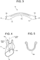
- Figure 5 A particular example of middle cross-section of the cross-member is shown in Figure 5 .
- the use of a closed cross-section makes it possible to achieve high values of torsional stiffness without having to resort to a torsion bar.
- the end portions 12b of the cross-member 12 are preferably straight portions which preferably extend in a horizontal plane, i.e. substantially in the same plane as the trailing arms 14. Accordingly, the end portions 12a have each a joining edge 24 for welded connection with the respective trailing arm 14 which extends rather smoothly and leads therefore to a correspondingly smooth stress distribution, without such high peaks as to cause structural problems. As already stated in the introductory part of the description, the use of horizontal straight end portions also allows to reduce the size problems of the cross-member.
- the end portions 12b of the cross-member 12 have a larger perimeter than the perimeter of the steel tube from which the cross-member 12 is obtained, i.e. than the perimeter of the middle portion 12a.
- the amount of increase in the perimeter of the cross-section of the end portions 12b with respect to the middle portion 12a varies depending on the specific application, remaining naturally within the limits due to the ability of the material of the cross-member to absorb the deformation.
- the resulting increase in the inertial characteristics of the joining area with the trailing arms leads to an increase in the mechanical strength and hence to the possibility to transmit a greater torsional moment, as well as to an increase in the stiffness of the twist-beam axle under lateral loads, and hence to an improvement of the handling performances of the vehicle.
- the joining portions 12c of the cross-member 12 are arched portions the concavity of which faces towards the opposite side (upwards) with respect to the middle portion 12a.
- the cross-member 12 has therefore a generally curved outline with a double change of concavity in the zones between the joining portions 12c and the middle portion 12a.
- the cross-member 12 is obtained by shaping and squashing a steel tube. More specifically, the first operation provides the cross-member with the required bowed outline, while the second operation provides the cross-member, particularly the middle portion thereof, with the required cross-section. These two operations are carried out by either cold- or hot-deformation of the steel tube by means of a special tool, that is to say, a shaping tool and a curving tool, respectively, which is moved in a given direction, typically a vertical direction.
- a special tool that is to say, a shaping tool and a curving tool, respectively, which is moved in a given direction, typically a vertical direction.
- the orientation of the shaping plane and the orientation of the camber plane can be chosen independently of each other, so as to allow the designer of the suspension to choose the best compromise among the different requirements, both in terms of layout and in terms of kinematic and elasto-kinematic performances of the suspension.
- the method of production of the cross-member provides, between the shaping operation and the curving operation, the possibility to rotate the work-piece by an angle ⁇ equal to the desired angle of inclination between the shaping plane and the camber plane. This angle can be clearly observed in the side view of Figure 4 .
- the method of production of the cross-member according to the invention basically comprises the following steps:
- step b The order in which the various steps listed above are carried out may be different from the one disclosed above, for instance the enlargement of the end portions of the cross-member may be carried out before providing the cross-member with the required arched shape, i.e. before the shaping step referred to above as step b). Some steps may even be omitted, in case they are not necessary.
Landscapes
- Engineering & Computer Science (AREA)
- Mechanical Engineering (AREA)
- Vehicle Body Suspensions (AREA)
Description
- The present invention relates to a cross-member for a twist-beam axle suspension for a motor vehicle, particularly for a rear suspension, as well as to method for its production.
- Rear twist-beam axle suspensions for motor vehicles are known which comprise a central cross-member and a pair of trailing arms which are rigidly connected to the opposite transverse ends of the cross-member and carry at their rear ends respective members for support of the wheel axles and at their front ends respective members for attachment to the vehicle body. While the trailing arms can be considered as rigid components, in that they are subject to negligible deformations in normal load conditions, the cross-member must have, on the other hand, a certain compliance, particularly under torsion, to allow the trailing arms to rotate elastically with respect to one another.
- Since the length of the cross-member is basically imposed by the specific application, as it is linked to the vehicle's tread, the torsional stiffness of the cross-member can be changed to take a given design value by properly shaping the cross-section of the cross-member, particularly the cross-section in the middle plane. In this connection, the cross-members currently used in the twist-beam axle suspensions for motor vehicles can be classified into two distinct categories. On the one hand, there are open-section cross-members consisting of a sheet-metal beam which is generally obtained by stamping or other plastic deformation process and has a cross-section with an outline of a variety of shapes, for instance of C-, U-, V- or Ω-live shape. On the other hand, there are closed-section cross-members consisting of a metal tubular beam which is plastically deformed, for instance by stamping or hydroforming process, so that its cross-section is given a predetermined shape such as to provide the beam with the desired torsional stiffness characteristics. In particular, the most important characteristic of the cross-section of the cross-member is the vertical position of the shear centre, as it directly and heavily affects the toe change of the suspension under roll, which is one the most important parameters for the assessment of the performance of the suspension in terms of handling. Cross-members with middle cross-sections having the same vertical size but different shapes and orientations have shear centres located at different heights and therefore affect the kinematic and elasto-kinematic performances of the suspension in different ways.
- Irrespective of the shape of the cross-section, the cross-members currently used in the twist-beam axle suspensions for motor vehicles extend generally horizontally, i.e. their axes lie in substantially horizontal planes. Such a conformation of the cross-member causes problems of space availability when the wheels carried by the trailing arms of the twist-beam axle are driving wheels. It is the case for instance of a rear twist-beam axle suspension for a four- or rear-wheel drive motor vehicle. The problems of space availability are basically due to the presence of the drive shaft which extends longitudinally, i.e. perpendicularly to the cross-member, thereby "crossing" the cross-member itself.
- In order to allow the use of a twist-beam axle suspension for the rear wheels of a four-wheel drive motor vehicle, a cross-member is known from European Patent application
EP-A-0 733 501 which is bowed or arched at least in a middle portion thereof. By virtue of the fact that the middle portion of the cross-member extends upwards, the drive shaft intended to drive the rear wheels can pass underneath the middle portion without interfering with it. The cross-member may be arched throughout its width or may have only an arched middle portion which smoothly joins with respective straight end portions. The end portions of the cross-member, whether arched or straight, are inclined to the horizontal. Since the trailing arms extend on the other hand horizontally, the welded joints between the ends of the cross-member and the trailing arms have therefore a rather irregular and complex shape which leads to an irregular stress distribution with peak values which may cause structural problems. - Moreover, the cross-member known from European Patent application
EP-A-0 733 501 has an open U-shaped cross-section. The choice of an open section does not allow to achieve particularly high values of torsional stiffness and makes therefore the cross-member not suitable for those application requiring a high torsional stiffness. Furthermore, the arched shape of the cross-member does not allow to add a torsion bar to increase the torsional stiffness of the cross-member. - European Patent application
EP-A-1 080 954 discloses a cross-member for a rear twist-beam axle suspension for a motor vehicle which is obtained by cold-forming of a steel tube. The cross-member extends horizontally and includes a middle portion having a double-wall substantially U-shaped cross-section, a pair of end portions having a circular cross-section corresponding to that of the steel tube from which the cross-member is obtained, and a pair of intermediate portions which join the middle portion with the respective end portions and have a cross-section whose shape varies continuously from a circular one at the transversely outer end to a U-like one at the transversely inner end. A method for the production of a cross-member for a twist-beam axle suspension according to the preamble of independent claim 1 is known fromWO2006/061424 . It is an object of the present invention to provide a bowed cross-member for a rear twist-beam axle suspension for a motor vehicle which has a high mechanical strength, which provide the designer with a wide freedom in the positioning of the shear centre of the middle cross-section, which allows the use of the cross-member also in those applications in which the available space is reduced by the presence not only of the drive shaft but also of other components (for instance of the tube connecting the fuel filler neck to the tank). This and other objects are fully achieved according to the invention by virtue of a method for the production of a cross-member for a twist-beam axle suspension for a motor vehicle comprising the steps defined in the enclosed independent claim 1, as well as by virtue of a cross-member for a twist-beam axle suspension for a motor vehicle having the characteristics defined in the enclosed independent claim 3. - Advantageous embodiments of a cross-member for a twist-beam axle suspension for a motor vehicle according to the invention are the subject matter of the dependent claims, the content of which is to be intended as integral and integrating part of the present description.
- In short, the invention is based on the idea of providing a bowed cross-member for a twist-beam axle suspension consisting of a single piece of steel of closed cross-section suitably shaped so as to have an arched middle portion, a pair of end portions intended to be securely connected each to a respective trailing arm of the suspension and a pair of arched joining portions, each of which is interposed between the middle portion and a respective end portion and has its concavity facing towards the opposite side with respect to the middle portion.
- The end portions are preferably horizontal straight portions. The cross-member is preferably obtained from a tube which is suitably squashed on at least part of the arched middle portion, whereby the shape of its middle cross-section is such as to provide the required inertial characteristics.
- By virtue of the arched middle portion, the cross-member can be used in rear twist-beam axle suspensions for four- or rear-wheel drive motor vehicles without interfering with the drive shaft. At the same time, by virtue of the horizontal straight end portions the cross-member on the one hand has less problems of space availability than the prior art discussed above and on the other hand has joining edges with the trailing arms which have a more regular shape than the prior art discussed above, whereby the above-mentioned problems due to the generation of stress peaks do not occur. Moreover, by virtue of the use of a squashed tube a middle cross-section is obtained which on the one hand is closed, and is therefore able to provide high values of torsional stiffness even without a torsion bar (which could not even be used due to the bowed shape of the cross-member), and on the other hand can be suitably shaped to locate the shear centre in the desired position in view of the kinematic and elasto-kinematic requirements of the suspension.
- According to another advantageous feature of the invention, the orientation of the middle plane of the squashing in the arched middle portion of the cross-member (hereinafter simply referred to as squashing plane) can be set independently of the orientation of the middle plane on which the curvilinear axis of the cross-member (hereinafter simply referred to as camber plane) extends. The squashing plane (the orientation of which is linked to the position of the shear centre of the middle cross-section, and hence to the kinematic and elasto-kinematic performances of the suspension) and the camber plane (the orientation of which is linked to the size constraints the cross-member must comply with) must not therefore coincide with each other, but can also be inclined to each other. The designer of the suspension has therefore a wide freedom in looking for the best compromise among the different requirements, both in terms of layout and in terms of kinematic and elasto-kinematic performances of the suspension.
- According to another feature of the invention, the end portions of the cross-member intended to be securely connected to the trailing arms of the twist-beam axle have an enlarged cross-section, that is to say, a cross-section of larger perimeter than that of the cross-section of the middle portion of the cross-member. The amount of the increase in the perimeter of the end portions with respect to the middle portion varies depending on the specific application, naturally within the limits linked to the ability of the material of the cross-member to absorb the deformation. The resulting increase in the inertial characteristics of the joining area with the trailing arms leads to an increase in the mechanical strength and hence to the possibility to transmit a greater torsion moment, as well as to an increase in the stiffness of the twist-beam axle under lateral loads, and hence to an improvement of the handling performances of the vehicle.
- Further features and advantages of the invention will become more apparent from the following detailed description, given purely by way of non-limiting example with reference to the appended drawings, in which:
-
Figure 1 is a perspective view of a twist-beam axle for a rear suspension of a motor vehicle having a cross-member according to a preferred embodiment of the present invention; -
Figure 2 is a perspective view of the cross-member of the twist-beam axle ofFigure 1 ; -
Figure 3 is a front elevation view of the cross-member of the twist-beam axle ofFigure 1 ; -
Figure 4 is a side view of the cross-member of the twist-beam axle ofFigure 1 ; and -
Figure 5 shows the middle cross-section of the cross-member of the twist-beam axle ofFigure 1 . - In the following description and claims, terms such as "longitudinal" and "transverse", "inner" and "outer", "front" and "rear", "upper" and "lower", are to be intended as referred to the mounted condition of the cross-member on the motor vehicle.
- With reference first to
Figure 1 , a twist-beam axle for a motor-vehicle suspension, particularly for a rear suspension, is generally indicated 10 and basically comprises abowed cross-member 12 and a pair of trailingarms 14 securely connected each to a respective side end of thecross-member 12. The trailingarms 14 carry respective wheel-carryingmembers 16,respective bushing seats 18 for articulated connection of the twist-beam axle 10 to the vehicle body (not shown),respective plates 20 for support of the springs (not shown), as well asrespective attachment members 22 for the shock-absorbers (also not shown). - The
cross-member 12 consists of a single tube of steel, preferably of manganese-boron steel (for instance, the 20MnB5 steel), or alternatively of low-alloy high-strength steel (cold- or hot-rolled), of multi-phase high-strength steel (cold- or hot-rolled), of two-phase high-strength steel (for instance, the DP600 steel), of ferritic-bainitic high-strength steel or again of high-alloy chromium stainless steel. With reference now toFigures 2 to 4 as well, thecross-member 12 comprises integrally amiddle portion 12a, a pair of transverselyopposite end portions 12b for connection of the cross-member with thetrailing arms 14, and a pair of joiningportions 12c which join each arespective end portion 12b with themiddle portion 12a. - The
middle portion 12a of thecross-member 12 has an arched shape, that is to say, its axis extends not along a straight line but along a curved arc-shaped line having a concavity facing downwards, and is therefore located at a greater height than theend portions 12b. The camber of thecross-member 12, that is to say, the vertical distance between themiddle portion 12a and theend portions 12b, may take significantly high values, preferably higher than 100 mm. Thecross-member 12 can thus be used in a rear twist-beam axle suspension for a rear- of four-wheel drive motor vehicle, since the drive shaft of the motor vehicle can pass underneath themiddle portion 12a of the cross-member without interfering with it. Themiddle portion 12a has a closed cross-section with a suitable shape, for instance with a C-, U-, V-, Ω-like shape, or again with a shape having squashed lobes, which is obtained by squashing of the steel tube forming the cross-member. A particular example of middle cross-section of the cross-member is shown inFigure 5 . As already stated in the introductory part of the description, the use of a closed cross-section makes it possible to achieve high values of torsional stiffness without having to resort to a torsion bar. - The
end portions 12b of thecross-member 12 are preferably straight portions which preferably extend in a horizontal plane, i.e. substantially in the same plane as thetrailing arms 14. Accordingly, theend portions 12a have each a joiningedge 24 for welded connection with the respectivetrailing arm 14 which extends rather smoothly and leads therefore to a correspondingly smooth stress distribution, without such high peaks as to cause structural problems. As already stated in the introductory part of the description, the use of horizontal straight end portions also allows to reduce the size problems of the cross-member. - According to an embodiment, the
end portions 12b of thecross-member 12 have a larger perimeter than the perimeter of the steel tube from which thecross-member 12 is obtained, i.e. than the perimeter of themiddle portion 12a. The amount of increase in the perimeter of the cross-section of theend portions 12b with respect to themiddle portion 12a varies depending on the specific application, remaining naturally within the limits due to the ability of the material of the cross-member to absorb the deformation. The resulting increase in the inertial characteristics of the joining area with the trailing arms leads to an increase in the mechanical strength and hence to the possibility to transmit a greater torsional moment, as well as to an increase in the stiffness of the twist-beam axle under lateral loads, and hence to an improvement of the handling performances of the vehicle. - The joining
portions 12c of thecross-member 12 are arched portions the concavity of which faces towards the opposite side (upwards) with respect to themiddle portion 12a. Thecross-member 12 has therefore a generally curved outline with a double change of concavity in the zones between the joiningportions 12c and themiddle portion 12a. - The
cross-member 12 is obtained by shaping and squashing a steel tube. More specifically, the first operation provides the cross-member with the required bowed outline, while the second operation provides the cross-member, particularly the middle portion thereof, with the required cross-section. These two operations are carried out by either cold- or hot-deformation of the steel tube by means of a special tool, that is to say, a shaping tool and a curving tool, respectively, which is moved in a given direction, typically a vertical direction. According to an advantageous feature of the invention, the orientation of the shaping plane and the orientation of the camber plane can be chosen independently of each other, so as to allow the designer of the suspension to choose the best compromise among the different requirements, both in terms of layout and in terms of kinematic and elasto-kinematic performances of the suspension. Such a possibility is provided by the fact that the method of production of the cross-member provides, between the shaping operation and the curving operation, the possibility to rotate the work-piece by an angle α equal to the desired angle of inclination between the shaping plane and the camber plane. This angle can be clearly observed in the side view ofFigure 4 . - The method of production of the cross-member according to the invention basically comprises the following steps:
- a) cutting a steel tube of proper diameter to the desired length;
- b) shaping the tube so as to provide it with the required curved outline;
- c) rotating the shaped tube, if necessary, to obtain a given angle of inclination between the shaping plane and the squashing plane;
- d) squashing the tube, particularly the arched middle portion thereof, to provide it with a cross-section having the required shape;
- e) leaving the tube to recover;
- f) enlarging and calibrating, if necessary, the end portions of the tube to such an extent that they have a cross-section with a larger perimeter than that of the cross-section of the tube;
- g) thermally treating the tube;
- h) calibrating the tube; and
- i) definitively cutting the tube by means of a hydraulic or mechanical cutting tool or by means of a laser or plasma cutting apparatus.
- The order in which the various steps listed above are carried out may be different from the one disclosed above, for instance the enlargement of the end portions of the cross-member may be carried out before providing the cross-member with the required arched shape, i.e. before the shaping step referred to above as step b). Some steps may even be omitted, in case they are not necessary.
- Naturally, the principle of the invention remaining unchanged, the embodiments and constructional details may vary widely with respect to those described and illustrated purely by way of non-limiting example, without thereby departing from the scope of the invention as defined in the appended claims.
Claims (8)
- Method for the production of a cross-member (12) for a twist-beam axle suspension (10) for a motor vehicle, particularly for a rear suspension, the method comprising the steps of:a) cutting a tubular straight piece of steel to the desired length;b) shaping a middle portion (12a) of said piece in a first plane so that this portion takes a given arched outline and is joined to a pair of end portions (12b) of the tube through a pair of joining portions (12c) each having a concavity facing towards the opposite side with respect to the middle portion (12a);c) squashing at least the middle portion (12a) of the piece in a second plane so as to provide the middle cross-section thereof with a given shape;characterized in that it further comprises, between steps b) and c), the step ofd) rotating the piece by a given angle to obtain a given angle of inclination between said first and second planes.
- Method according to claim 1, further comprising the step ofe) enlarging each of the end portions (12b) of the piece so that the cross-section thereof has a larger perimeter than the middle cross-section of the middle portion (12a).
- Cross-member (12) for a twist-beam axle suspension (10) for a motor vehicle, particularly for a rear suspension, consisting of a single tube of steel which has a closed cross-section and integrally forms- an arched middle portion (12a),- a pair of end portions (12b) which are arranged to be securely connected to respective trailing arms (14) of the twist-beam axle (10), and- a pair of arched joining portions (12c), each of which is interposed between the middle portion (12a) and a respective end portion (12b) and has a concavity facing towards the opposite side with respect to the middle portion (12a),characterized in that the cross-member (12) is obtainable by the method of claim 1.
- Cross-member according to claim 3, wherein the end portions (12b) are straight portions.
- Cross-member according to claim 3 or claim 4, wherein the steel of said single tube of steel is selected within the group comprising:- manganese-boron steel;- low-alloy high-strength steel, either cold- or hot-rolled,- multi-phase high-strength steel, either cold- or hot-rolled,- two-phase high-strength steel,- ferritic-bainitic high-strength steel, and- high-alloy chromium stainless steel.
- Cross-member according to any of claims 3 to 5, wherein the end portions (12b) have a cross-section with a larger perimeter than that of the cross-section of the middle portion (12a).
- Twist-beam axle suspension for a motor vehicle, particularly a rear suspension, comprising a cross-member (12) according to any of claims 3 to 6 and a pair of trailing arms (14) securely connected each to a respective end portion (12b) of the cross-member (12).
- Suspension according to claim 7, wherein the axes of the trailing arms (14) extend in the same plane and wherein the axes of the end portions (12b) of the cross-member (12) extend in said plane.
Applications Claiming Priority (2)
| Application Number | Priority Date | Filing Date | Title |
|---|---|---|---|
| IT000521A ITTO20080521A1 (en) | 2008-07-08 | 2008-07-08 | CROSSBEAM FOR A REAR BRIDGE SUSPENSION WITH TORCH FOR MOTOR VEHICLES AND PROCEDURE FOR ITS MANUFACTURING |
| PCT/IB2008/055103 WO2010004370A1 (en) | 2008-07-08 | 2008-12-04 | Cross-member for a rear twist-beam axle suspension for a motor vechicle and method for its production |
Publications (2)
| Publication Number | Publication Date |
|---|---|
| EP2310217A1 EP2310217A1 (en) | 2011-04-20 |
| EP2310217B1 true EP2310217B1 (en) | 2017-04-26 |
Family
ID=40513855
Family Applications (1)
| Application Number | Title | Priority Date | Filing Date |
|---|---|---|---|
| EP08875873.5A Active EP2310217B1 (en) | 2008-07-08 | 2008-12-04 | Cross-member for a rear twist-beam axle suspension for a motor vechicle and method for its production |
Country Status (7)
| Country | Link |
|---|---|
| US (1) | US20110115183A1 (en) |
| EP (1) | EP2310217B1 (en) |
| JP (2) | JP5789510B2 (en) |
| BR (1) | BRPI0822508B1 (en) |
| IT (1) | ITTO20080521A1 (en) |
| RU (1) | RU2517272C2 (en) |
| WO (1) | WO2010004370A1 (en) |
Cited By (1)
| Publication number | Priority date | Publication date | Assignee | Title |
|---|---|---|---|---|
| DE102018100989B3 (en) | 2018-01-17 | 2019-02-14 | Benteler Automobiltechnik Gmbh | Method for producing a bent torsion profile and torsion profile |
Families Citing this family (35)
| Publication number | Priority date | Publication date | Assignee | Title |
|---|---|---|---|---|
| CA2644464C (en) * | 2008-10-17 | 2010-04-20 | Arcelormittal Tubular Products Canada Inc. | Twist-axle of variable wall thickness |
| DE102010036949A1 (en) * | 2010-08-11 | 2012-02-16 | Muhr Und Bender Kg | Cross member for a torsion beam axle |
| BR112013012269A2 (en) * | 2010-11-29 | 2018-08-28 | Multimatic Patentco Llc | torsion bar for a suspension system |
| DE102011086480B4 (en) * | 2011-11-16 | 2021-01-28 | Saf-Holland Gmbh | Axle unit for commercial vehicles |
| CN104093503A (en) * | 2012-02-01 | 2014-10-08 | 麦格纳国际公司 | Lateral brace and method of forming a lateral brace |
| DE102012104909A1 (en) * | 2012-06-06 | 2013-12-12 | Benteler Automobiltechnik Gmbh | Wishbone and method for producing the wishbone |
| MX368083B (en) * | 2012-09-20 | 2019-09-19 | Nippon Steel Corp Star | Hardened steel tube member, automobile axle beam using hardened steel tube member, and method for manufacturing hardened steel tube member. |
| EP2746155B1 (en) * | 2012-12-21 | 2015-07-08 | Bell Helicopter Textron Inc. | Helicopter skid landing gear |
| US10300760B1 (en) | 2015-03-18 | 2019-05-28 | Apple Inc. | Fully-actuated suspension system |
| KR101673343B1 (en) * | 2015-05-06 | 2016-11-07 | 현대자동차 주식회사 | Coupled torsion beam axle of vehicles |
| CN104890465B (en) * | 2015-06-29 | 2017-11-03 | 芜湖中瑞弹簧有限公司 | A kind of stabilizer bar of motor vehicle structure |
| DE202015103545U1 (en) | 2015-06-30 | 2015-07-23 | Ford Global Technologies, Llc | Torsionsquerträger, in particular for a torsion beam axle and motor vehicle comprising the Torsionsquerträger |
| DE102016210458B4 (en) | 2015-06-30 | 2022-03-31 | Ford Global Technologies, Llc | Torsion cross member, in particular for a torsion beam axle and motor vehicle having the torsion cross member |
| DE102015212125A1 (en) | 2015-06-30 | 2017-01-05 | Ford Global Technologies, Llc | Torsionsquerträger, in particular for a torsion beam axle and motor vehicle comprising the Torsionsquerträger |
| DE102016219140A1 (en) | 2016-10-04 | 2018-04-05 | Ford Global Technologies, Llc | Rear suspension for a vehicle |
| DE202016105743U1 (en) | 2016-10-04 | 2016-10-26 | Ford Global Technologies, Llc | Rear suspension for a vehicle |
| DE102016219138B4 (en) | 2016-10-04 | 2026-01-15 | Ford Global Technologies, Llc | Rear axle suspension for a vehicle |
| US10814690B1 (en) | 2017-04-18 | 2020-10-27 | Apple Inc. | Active suspension system with energy storage device |
| CN110997362B (en) | 2017-05-08 | 2023-07-28 | 苹果公司 | active suspension system |
| US10899340B1 (en) | 2017-06-21 | 2021-01-26 | Apple Inc. | Vehicle with automated subsystems |
| US11173766B1 (en) | 2017-09-07 | 2021-11-16 | Apple Inc. | Suspension system with locking structure |
| US11065931B1 (en) | 2017-09-15 | 2021-07-20 | Apple Inc. | Active suspension system |
| US11124035B1 (en) | 2017-09-25 | 2021-09-21 | Apple Inc. | Multi-stage active suspension actuator |
| US10960723B1 (en) | 2017-09-26 | 2021-03-30 | Apple Inc. | Wheel-mounted suspension actuators |
| US11285773B1 (en) | 2018-09-12 | 2022-03-29 | Apple Inc. | Control system |
| US11634167B1 (en) | 2018-09-14 | 2023-04-25 | Apple Inc. | Transmitting axial and rotational movement to a hub |
| US11345209B1 (en) | 2019-06-03 | 2022-05-31 | Apple Inc. | Suspension systems |
| US11938922B1 (en) | 2019-09-23 | 2024-03-26 | Apple Inc. | Motion control system |
| US11179991B1 (en) | 2019-09-23 | 2021-11-23 | Apple Inc. | Suspension systems |
| US11707961B1 (en) | 2020-04-28 | 2023-07-25 | Apple Inc. | Actuator with reinforcing structure for torsion resistance |
| US11828339B1 (en) | 2020-07-07 | 2023-11-28 | Apple Inc. | Vibration control system |
| CN117396339A (en) | 2021-06-07 | 2024-01-12 | 苹果公司 | mass damper system |
| US12077232B2 (en) * | 2022-02-25 | 2024-09-03 | Norco Industries, Inc. | Trailer axle |
| US12251973B2 (en) | 2022-06-10 | 2025-03-18 | Apple Inc. | Vibration absorber |
| US12168375B1 (en) | 2023-01-26 | 2024-12-17 | Apple Inc. | Motion control system |
Family Cites Families (26)
| Publication number | Priority date | Publication date | Assignee | Title |
|---|---|---|---|---|
| SU998145A1 (en) * | 1981-10-23 | 1983-02-23 | Центральный Ордена Трудового Красного Знамени Научно-Исследовательский Автомобильный И Автомоторный Институт "Нами" | Motor vehicle rear wheel suspension |
| FR2599674B1 (en) * | 1986-06-10 | 1990-06-08 | Peugeot | REAR AXLE OF MOTOR VEHICLE |
| FR2711407B1 (en) * | 1993-10-19 | 1996-01-26 | Allevard Sa | Improvements to metal torsion bars. |
| DE4447971B4 (en) * | 1994-05-13 | 2007-03-29 | GM Global Technology Operations, Inc., Detroit | Motor vehicle rear axle |
| JP3546564B2 (en) * | 1995-03-24 | 2004-07-28 | トヨタ自動車株式会社 | Twist beam suspension |
| DE19653959C1 (en) * | 1996-12-21 | 1998-02-05 | Benteler Werke Ag | Cross-bearer forming indirect component part of compound steering shaft |
| JP3716610B2 (en) * | 1998-03-30 | 2005-11-16 | マツダ株式会社 | Car rear wheel suspension system |
| DE19933108A1 (en) * | 1999-07-15 | 2001-02-01 | Benteler Werke Ag | Vehicle dead beam axle, with U-shaped cross-bearer having box ends |
| ATE399661T1 (en) * | 1999-09-02 | 2008-07-15 | Benteler Werke Ag | CROSS MEMBER AS A COMPONENT OF A CONVERSION BEAM AXLE |
| JP2002127724A (en) * | 2000-08-14 | 2002-05-08 | Futaba Industrial Co Ltd | Torsion beam type suspension |
| DE20101602U1 (en) * | 2001-01-31 | 2001-04-05 | Benteler Automobiltechnik GmbH & Co. KG, 33104 Paderborn | Twist beam axle |
| DE10207151C1 (en) * | 2002-02-20 | 2003-02-13 | Benteler Automobiltechnik Gmbh | Compound steering axle has transverse strut between 2 longitudinal steering shafts formed from upper and lower shells |
| JP2004299513A (en) * | 2003-03-31 | 2004-10-28 | Suzuki Motor Corp | Torsion beam suspension |
| US7377041B2 (en) * | 2003-06-18 | 2008-05-27 | Donghee Industrial Co., Ltd. | Torsion beam type suspension, method for forming torsion beam, and apparatus for forming torsion beam |
| FR2874541B1 (en) * | 2004-09-02 | 2006-11-03 | Auto Chassis Internat Snc Snc | FLEXIBLE AXLE OF A MOTOR VEHICLE COMPRISING A CROSSING INCORPORATING ANTI-DEVICE FUNCTION, TRAVERSE, METHOD OF MANUFACTURE AND VEHICLE THEREFOR |
| KR100554310B1 (en) * | 2004-09-21 | 2006-02-24 | 주식회사화신 | Beam manufacturing apparatus of torsion beam for automobile rear suspension |
| FR2878786B1 (en) * | 2004-12-08 | 2007-02-23 | Auto Chassis Internat Snc Snc | FLEXIBLE AXLE COMPRISING A TROPEZOIDAL SECTION RAIL, TRAVERSE, VEHICLE AND METHOD FOR MANUFACTURING THE SAME |
| BRPI0608366B1 (en) * | 2005-03-04 | 2020-04-28 | Hendrickson International Corporation | axis with displaced center and method for its production |
| FR2898543A1 (en) * | 2006-03-20 | 2007-09-21 | Renault Sas | REAR AXLE OF A MOTOR VEHICLE WITH A PANHARD BAR AND HINGED TRAVERSE AND A CORRESPONDING VEHICLE |
| KR100958977B1 (en) * | 2007-07-25 | 2010-05-20 | 주식회사 포스코 | Tubular torsion beam for rear wheel suspension of automobile and manufacturing method thereof |
| EP2020314A1 (en) * | 2007-08-01 | 2009-02-04 | GM Global Technology Operations, Inc. | Driven motor vehicle twist beam rear axle |
| CA2698249C (en) * | 2007-09-05 | 2016-01-12 | Magna International Inc. | Twist beam with interlock |
| US7862058B2 (en) * | 2008-03-12 | 2011-01-04 | Hendrickson Usa L.L.C. | Fabricated vehicle axle |
| JP2009274077A (en) * | 2008-05-12 | 2009-11-26 | Nippon Steel Corp | Method of press-forming tubular member having special-shaped cross section and tubular member having special-shaped cross section formed by the same method |
| JP4858624B2 (en) * | 2009-04-01 | 2012-01-18 | Jfeスチール株式会社 | Torsion beam manufacturing method and torsion beam |
| DE102009031846A1 (en) * | 2009-07-03 | 2011-01-05 | GM Global Technology Operations, Inc., Detroit | Rear axle of the compound type of steering wheel for motor vehicles |
-
2008
- 2008-07-08 IT IT000521A patent/ITTO20080521A1/en unknown
- 2008-12-04 JP JP2011517252A patent/JP5789510B2/en active Active
- 2008-12-04 RU RU2011104341/11A patent/RU2517272C2/en active
- 2008-12-04 US US13/002,841 patent/US20110115183A1/en not_active Abandoned
- 2008-12-04 EP EP08875873.5A patent/EP2310217B1/en active Active
- 2008-12-04 WO PCT/IB2008/055103 patent/WO2010004370A1/en not_active Ceased
- 2008-12-04 BR BRPI0822508-7A patent/BRPI0822508B1/en not_active IP Right Cessation
-
2014
- 2014-05-13 JP JP2014099815A patent/JP2014196102A/en active Pending
Non-Patent Citations (1)
| Title |
|---|
| None * |
Cited By (1)
| Publication number | Priority date | Publication date | Assignee | Title |
|---|---|---|---|---|
| DE102018100989B3 (en) | 2018-01-17 | 2019-02-14 | Benteler Automobiltechnik Gmbh | Method for producing a bent torsion profile and torsion profile |
Also Published As
| Publication number | Publication date |
|---|---|
| RU2517272C2 (en) | 2014-05-27 |
| JP2011527262A (en) | 2011-10-27 |
| EP2310217A1 (en) | 2011-04-20 |
| US20110115183A1 (en) | 2011-05-19 |
| WO2010004370A1 (en) | 2010-01-14 |
| JP5789510B2 (en) | 2015-10-07 |
| RU2011104341A (en) | 2012-08-20 |
| ITTO20080521A1 (en) | 2010-01-08 |
| BRPI0822508A2 (en) | 2015-07-07 |
| JP2014196102A (en) | 2014-10-16 |
| BRPI0822508B1 (en) | 2019-07-09 |
Similar Documents
| Publication | Publication Date | Title |
|---|---|---|
| US20110115183A1 (en) | Cross-member for a rear twist-beam axle suspension for a motor-vehicle and method for its production | |
| JP3546564B2 (en) | Twist beam suspension | |
| US9527368B2 (en) | Semi-independent suspension system for a low-floor vechicle | |
| CA2974205C (en) | Vehicle twist axle assembly | |
| CA2704643A1 (en) | Suspension system for a vehicle and method | |
| US20090033142A1 (en) | Powered motor vehicle rear axle of a twist-beam axle type | |
| EP2222489B1 (en) | Cross-member for a twist-beam axle rear suspension for a motor vehicle | |
| CA2909707A1 (en) | Twist beam with joined inner and outer parts | |
| CA2967051C (en) | Vehicle twist axle assembly | |
| US10086874B2 (en) | Modular vehicle platform and related methods | |
| US9102210B2 (en) | Suspension system for a vehicle and method | |
| EP3954557B1 (en) | Support arm | |
| JP2008522893A (en) | Flexible axle comprising a trapezoidal cross member, cross member, vehicle, and manufacturing method | |
| EP2075146B1 (en) | Twist-beam rear axle and method for producing a cross member | |
| KR101027409B1 (en) | Car suspension system | |
| JPH11115430A (en) | Suspension arm | |
| WO2016073892A1 (en) | Vehicle twist axle assembly | |
| WO2022094063A1 (en) | Twist axle assembly |
Legal Events
| Date | Code | Title | Description |
|---|---|---|---|
| PUAI | Public reference made under article 153(3) epc to a published international application that has entered the european phase |
Free format text: ORIGINAL CODE: 0009012 |
|
| 17P | Request for examination filed |
Effective date: 20110202 |
|
| AK | Designated contracting states |
Kind code of ref document: A1 Designated state(s): AT BE BG CH CY CZ DE DK EE ES FI FR GB GR HR HU IE IS IT LI LT LU LV MC MT NL NO PL PT RO SE SI SK TR |
|
| AX | Request for extension of the european patent |
Extension state: AL BA MK RS |
|
| DAX | Request for extension of the european patent (deleted) | ||
| 17Q | First examination report despatched |
Effective date: 20120709 |
|
| GRAP | Despatch of communication of intention to grant a patent |
Free format text: ORIGINAL CODE: EPIDOSNIGR1 |
|
| INTG | Intention to grant announced |
Effective date: 20161026 |
|
| GRAJ | Information related to disapproval of communication of intention to grant by the applicant or resumption of examination proceedings by the epo deleted |
Free format text: ORIGINAL CODE: EPIDOSDIGR1 |
|
| GRAR | Information related to intention to grant a patent recorded |
Free format text: ORIGINAL CODE: EPIDOSNIGR71 |
|
| GRAS | Grant fee paid |
Free format text: ORIGINAL CODE: EPIDOSNIGR3 |
|
| GRAA | (expected) grant |
Free format text: ORIGINAL CODE: 0009210 |
|
| INTC | Intention to grant announced (deleted) | ||
| AK | Designated contracting states |
Kind code of ref document: B1 Designated state(s): AT BE BG CH CY CZ DE DK EE ES FI FR GB GR HR HU IE IS IT LI LT LU LV MC MT NL NO PL PT RO SE SI SK TR |
|
| INTG | Intention to grant announced |
Effective date: 20170320 |
|
| REG | Reference to a national code |
Ref country code: GB Ref legal event code: FG4D |
|
| REG | Reference to a national code |
Ref country code: CH Ref legal event code: EP |
|
| REG | Reference to a national code |
Ref country code: AT Ref legal event code: REF Ref document number: 887543 Country of ref document: AT Kind code of ref document: T Effective date: 20170515 |
|
| REG | Reference to a national code |
Ref country code: IE Ref legal event code: FG4D |
|
| REG | Reference to a national code |
Ref country code: DE Ref legal event code: R096 Ref document number: 602008050000 Country of ref document: DE |
|
| REG | Reference to a national code |
Ref country code: NL Ref legal event code: MP Effective date: 20170426 |
|
| REG | Reference to a national code |
Ref country code: LT Ref legal event code: MG4D |
|
| REG | Reference to a national code |
Ref country code: AT Ref legal event code: MK05 Ref document number: 887543 Country of ref document: AT Kind code of ref document: T Effective date: 20170426 |
|
| PG25 | Lapsed in a contracting state [announced via postgrant information from national office to epo] |
Ref country code: NL Free format text: LAPSE BECAUSE OF FAILURE TO SUBMIT A TRANSLATION OF THE DESCRIPTION OR TO PAY THE FEE WITHIN THE PRESCRIBED TIME-LIMIT Effective date: 20170426 |
|
| PG25 | Lapsed in a contracting state [announced via postgrant information from national office to epo] |
Ref country code: GR Free format text: LAPSE BECAUSE OF FAILURE TO SUBMIT A TRANSLATION OF THE DESCRIPTION OR TO PAY THE FEE WITHIN THE PRESCRIBED TIME-LIMIT Effective date: 20170727 Ref country code: HR Free format text: LAPSE BECAUSE OF FAILURE TO SUBMIT A TRANSLATION OF THE DESCRIPTION OR TO PAY THE FEE WITHIN THE PRESCRIBED TIME-LIMIT Effective date: 20170426 Ref country code: NO Free format text: LAPSE BECAUSE OF FAILURE TO SUBMIT A TRANSLATION OF THE DESCRIPTION OR TO PAY THE FEE WITHIN THE PRESCRIBED TIME-LIMIT Effective date: 20170726 Ref country code: ES Free format text: LAPSE BECAUSE OF FAILURE TO SUBMIT A TRANSLATION OF THE DESCRIPTION OR TO PAY THE FEE WITHIN THE PRESCRIBED TIME-LIMIT Effective date: 20170426 Ref country code: FI Free format text: LAPSE BECAUSE OF FAILURE TO SUBMIT A TRANSLATION OF THE DESCRIPTION OR TO PAY THE FEE WITHIN THE PRESCRIBED TIME-LIMIT Effective date: 20170426 Ref country code: LT Free format text: LAPSE BECAUSE OF FAILURE TO SUBMIT A TRANSLATION OF THE DESCRIPTION OR TO PAY THE FEE WITHIN THE PRESCRIBED TIME-LIMIT Effective date: 20170426 Ref country code: AT Free format text: LAPSE BECAUSE OF FAILURE TO SUBMIT A TRANSLATION OF THE DESCRIPTION OR TO PAY THE FEE WITHIN THE PRESCRIBED TIME-LIMIT Effective date: 20170426 |
|
| REG | Reference to a national code |
Ref country code: FR Ref legal event code: PLFP Year of fee payment: 10 |
|
| PG25 | Lapsed in a contracting state [announced via postgrant information from national office to epo] |
Ref country code: PL Free format text: LAPSE BECAUSE OF FAILURE TO SUBMIT A TRANSLATION OF THE DESCRIPTION OR TO PAY THE FEE WITHIN THE PRESCRIBED TIME-LIMIT Effective date: 20170426 Ref country code: IS Free format text: LAPSE BECAUSE OF FAILURE TO SUBMIT A TRANSLATION OF THE DESCRIPTION OR TO PAY THE FEE WITHIN THE PRESCRIBED TIME-LIMIT Effective date: 20170826 Ref country code: BG Free format text: LAPSE BECAUSE OF FAILURE TO SUBMIT A TRANSLATION OF THE DESCRIPTION OR TO PAY THE FEE WITHIN THE PRESCRIBED TIME-LIMIT Effective date: 20170726 Ref country code: SE Free format text: LAPSE BECAUSE OF FAILURE TO SUBMIT A TRANSLATION OF THE DESCRIPTION OR TO PAY THE FEE WITHIN THE PRESCRIBED TIME-LIMIT Effective date: 20170426 Ref country code: LV Free format text: LAPSE BECAUSE OF FAILURE TO SUBMIT A TRANSLATION OF THE DESCRIPTION OR TO PAY THE FEE WITHIN THE PRESCRIBED TIME-LIMIT Effective date: 20170426 |
|
| REG | Reference to a national code |
Ref country code: DE Ref legal event code: R097 Ref document number: 602008050000 Country of ref document: DE |
|
| PG25 | Lapsed in a contracting state [announced via postgrant information from national office to epo] |
Ref country code: RO Free format text: LAPSE BECAUSE OF FAILURE TO SUBMIT A TRANSLATION OF THE DESCRIPTION OR TO PAY THE FEE WITHIN THE PRESCRIBED TIME-LIMIT Effective date: 20170426 Ref country code: DK Free format text: LAPSE BECAUSE OF FAILURE TO SUBMIT A TRANSLATION OF THE DESCRIPTION OR TO PAY THE FEE WITHIN THE PRESCRIBED TIME-LIMIT Effective date: 20170426 Ref country code: CZ Free format text: LAPSE BECAUSE OF FAILURE TO SUBMIT A TRANSLATION OF THE DESCRIPTION OR TO PAY THE FEE WITHIN THE PRESCRIBED TIME-LIMIT Effective date: 20170426 Ref country code: SK Free format text: LAPSE BECAUSE OF FAILURE TO SUBMIT A TRANSLATION OF THE DESCRIPTION OR TO PAY THE FEE WITHIN THE PRESCRIBED TIME-LIMIT Effective date: 20170426 Ref country code: EE Free format text: LAPSE BECAUSE OF FAILURE TO SUBMIT A TRANSLATION OF THE DESCRIPTION OR TO PAY THE FEE WITHIN THE PRESCRIBED TIME-LIMIT Effective date: 20170426 |
|
| PLBE | No opposition filed within time limit |
Free format text: ORIGINAL CODE: 0009261 |
|
| STAA | Information on the status of an ep patent application or granted ep patent |
Free format text: STATUS: NO OPPOSITION FILED WITHIN TIME LIMIT |
|
| 26N | No opposition filed |
Effective date: 20180129 |
|
| PG25 | Lapsed in a contracting state [announced via postgrant information from national office to epo] |
Ref country code: SI Free format text: LAPSE BECAUSE OF FAILURE TO SUBMIT A TRANSLATION OF THE DESCRIPTION OR TO PAY THE FEE WITHIN THE PRESCRIBED TIME-LIMIT Effective date: 20170426 |
|
| REG | Reference to a national code |
Ref country code: CH Ref legal event code: PL |
|
| GBPC | Gb: european patent ceased through non-payment of renewal fee |
Effective date: 20171204 |
|
| REG | Reference to a national code |
Ref country code: IE Ref legal event code: MM4A |
|
| PG25 | Lapsed in a contracting state [announced via postgrant information from national office to epo] |
Ref country code: MT Free format text: LAPSE BECAUSE OF NON-PAYMENT OF DUE FEES Effective date: 20171204 Ref country code: LU Free format text: LAPSE BECAUSE OF NON-PAYMENT OF DUE FEES Effective date: 20171204 |
|
| REG | Reference to a national code |
Ref country code: BE Ref legal event code: MM Effective date: 20171231 |
|
| PG25 | Lapsed in a contracting state [announced via postgrant information from national office to epo] |
Ref country code: IE Free format text: LAPSE BECAUSE OF NON-PAYMENT OF DUE FEES Effective date: 20171204 |
|
| PG25 | Lapsed in a contracting state [announced via postgrant information from national office to epo] |
Ref country code: CH Free format text: LAPSE BECAUSE OF NON-PAYMENT OF DUE FEES Effective date: 20171231 Ref country code: BE Free format text: LAPSE BECAUSE OF NON-PAYMENT OF DUE FEES Effective date: 20171231 Ref country code: GB Free format text: LAPSE BECAUSE OF NON-PAYMENT OF DUE FEES Effective date: 20171204 Ref country code: LI Free format text: LAPSE BECAUSE OF NON-PAYMENT OF DUE FEES Effective date: 20171231 |
|
| PG25 | Lapsed in a contracting state [announced via postgrant information from national office to epo] |
Ref country code: MC Free format text: LAPSE BECAUSE OF FAILURE TO SUBMIT A TRANSLATION OF THE DESCRIPTION OR TO PAY THE FEE WITHIN THE PRESCRIBED TIME-LIMIT Effective date: 20170426 Ref country code: HU Free format text: LAPSE BECAUSE OF FAILURE TO SUBMIT A TRANSLATION OF THE DESCRIPTION OR TO PAY THE FEE WITHIN THE PRESCRIBED TIME-LIMIT; INVALID AB INITIO Effective date: 20081204 |
|
| PG25 | Lapsed in a contracting state [announced via postgrant information from national office to epo] |
Ref country code: CY Free format text: LAPSE BECAUSE OF NON-PAYMENT OF DUE FEES Effective date: 20170426 |
|
| PG25 | Lapsed in a contracting state [announced via postgrant information from national office to epo] |
Ref country code: TR Free format text: LAPSE BECAUSE OF FAILURE TO SUBMIT A TRANSLATION OF THE DESCRIPTION OR TO PAY THE FEE WITHIN THE PRESCRIBED TIME-LIMIT Effective date: 20170426 |
|
| PG25 | Lapsed in a contracting state [announced via postgrant information from national office to epo] |
Ref country code: PT Free format text: LAPSE BECAUSE OF FAILURE TO SUBMIT A TRANSLATION OF THE DESCRIPTION OR TO PAY THE FEE WITHIN THE PRESCRIBED TIME-LIMIT Effective date: 20170426 |
|
| PGFP | Annual fee paid to national office [announced via postgrant information from national office to epo] |
Ref country code: FR Payment date: 20231122 Year of fee payment: 16 Ref country code: DE Payment date: 20231121 Year of fee payment: 16 |
|
| REG | Reference to a national code |
Ref country code: DE Ref legal event code: R119 Ref document number: 602008050000 Country of ref document: DE |
|
| PG25 | Lapsed in a contracting state [announced via postgrant information from national office to epo] |
Ref country code: DE Free format text: LAPSE BECAUSE OF NON-PAYMENT OF DUE FEES Effective date: 20250701 |
|
| PGFP | Annual fee paid to national office [announced via postgrant information from national office to epo] |
Ref country code: IT Payment date: 20231121 Year of fee payment: 16 |
|
| PG25 | Lapsed in a contracting state [announced via postgrant information from national office to epo] |
Ref country code: FR Free format text: LAPSE BECAUSE OF NON-PAYMENT OF DUE FEES Effective date: 20241231 |