EP2309836B1 - Power take-off shaft guards - Google Patents
Power take-off shaft guards Download PDFInfo
- Publication number
- EP2309836B1 EP2309836B1 EP09772342A EP09772342A EP2309836B1 EP 2309836 B1 EP2309836 B1 EP 2309836B1 EP 09772342 A EP09772342 A EP 09772342A EP 09772342 A EP09772342 A EP 09772342A EP 2309836 B1 EP2309836 B1 EP 2309836B1
- Authority
- EP
- European Patent Office
- Prior art keywords
- guard
- guard member
- vertically extending
- pto shaft
- arrangement according
- Prior art date
- Legal status (The legal status is an assumption and is not a legal conclusion. Google has not performed a legal analysis and makes no representation as to the accuracy of the status listed.)
- Active
Links
Images




Classifications
-
- A—HUMAN NECESSITIES
- A01—AGRICULTURE; FORESTRY; ANIMAL HUSBANDRY; HUNTING; TRAPPING; FISHING
- A01B—SOIL WORKING IN AGRICULTURE OR FORESTRY; PARTS, DETAILS, OR ACCESSORIES OF AGRICULTURAL MACHINES OR IMPLEMENTS, IN GENERAL
- A01B71/00—Construction or arrangement of setting or adjusting mechanisms, of implement or tool drive or of power take-off; Means for protecting parts against dust, or the like; Adapting machine elements to or for agricultural purposes
- A01B71/08—Means for protecting against dust or the like, or for cleaning agricultural implements
Definitions
- This invention relates to guards for Power Take-Off (PTO) shafts used on tractors or similar vehicles.
- PTO Power Take-Off
- PTO guards which can be moved between an extended position in which the guard provides protection from injury from an associated PTO shaft and a retracted position when such protection is not required such a guard is known from US 4 553 950 . It is also known to have removeable PTO guards which are detached when the protection is not required but these moveable guards impose a storage problem.
- a PTO shaft guard arrangement in which a guard member is of inverted U-shaped form and is pivotally mounted on a support structure the arrangement being characterised in that the support structure comprises a pair of generally vertically extending plates located on opposite sides of the associated PTO shaft between which the guard member is pivotally mounted for movement between a non-operative retracted position and an operative extended position, the guard member having an over-centre spring means for holding the guard member in both the retracted and extended positions.
- Such an arrangement holds the guard member in either the retracted or extended positions thus preventing rattling and can be easily pivoted between the positions by movement initially against the action of the spring means which, in the second part of such movement, is subsequently assisted by the spring means.
- the support structure may comprise a pair of generally vertically extending plates located on opposite sides of the associated PTO shaft, the guard member being of inverted general U-shaped form with each side of the inverted U-shape guard pivotally mounted on a respective generally vertically extending plate.
- the spring means may comprise a pair of bow springs, one end of each bow spring being mounted on the adjacent generally vertically extending plate and the other end being mounted on the adjacent support arm.
- Each generally vertically extending plate may include a generally vertically extending slot, a towing hitch being vertically slidable between the plates in the slots and lockable relative to the plates at various heights.
- Fixed side protection plates may extend between the vertically extending plates and the tractor chassis on which the vertically extending plates are mounted, each support arm moving in a slot provided in its respective side protection plate.
- a tractor chassis 10 is provided with a PTO shaft 11 which emerges from the chassis between two vertical hitch support plates 12, each provided with a vertically extending slot 13 in which a vertically moveable hitch (not shown) is slideable.
- a PTO guard member 14 is pivotally mounted on the plates 12 by two arms 15 which are screwed to the guard at 15a and which pivot about pins 16 screwed into the plates 12.
- Each vertical plate 12 has a cut-out 17 to save weight which is covered by a side protection plate 18 secured to the adjacent vertical plate 12 by bolts 19.
- Each protection plate 18 has a slot 20 through which the respective support arm 15 for the PTO shaft cover 14 extends.
- a bow spring 21 acts between a pin 22 on the support arm 15 and a pin 23 mounted on the adjacent vertical plate 12.
- a top protection plate 24 is bolted on the rear of the chassis at 25 and extends between the edge portion 14a of the guard and the chassis when the guard is in its extended position shown in Figure 4 .
- Figure 4 shows the PTO shaft guard in its fully extended position which the bow spring 21 applies a force B to the guard which generates a clockwise turning moment about the axis 16 thus tending to hold the guard in its fully extended position.
- the clockwise movement of the arm 15 is limited by the edge 12a of the plate 12.
- the guard 14 has a tab 14b allowing the operator to easily grip the guard for moving the guard between its retracted and extended position.
- the bow springs 21 initially oppose the movement of the guard from its current retracted or extended position, but when the pins 21 cross the lines 26 between the pivots 16 and the pins 23, the spring go "over centre” and assist in moving the guard towards its new position.
- the front edge of the guard 14 has cam surfaces 27 which extends across the vertical slots 13 in the vertical plates 12. If a vertically moveable hitch is mounted in the slots 12 and is moved upwardly it will contact this cam surfaces 27 and move the PTO guard towards its retracted position. Initially this movement will be opposed by the bow springs 21 but after the mounting pins 22 move "over centre” this spring force will assist in retracting the PTO guard.
- FIGS 7 to 11 show different arrangements of the shaft guard 14 according to the invention.
- the PTO shaft and hitch support plates 12 are not shown in these drawings. All other features, where present are indicated using the same reference numbers as in figures 1 to 6 .
- Figure 7 shows a perspective view of the guard 14 from the front as it would be viewed if attached to a vehicle having a PTO shaft.
- the guard 14 has two side portions 40 and a central portion 41 which form a generally flat bottomed inverted U-shape.
- Figure 8 shows a perspective view of the guard in which side portions 40 are fitted with releasably attachable adapter side members 42.
- the adapter side members 42 protrude inwards towards each other and are attached to side portions 40 by fastening means such as bolts, or screws.
- the attachment means can be seen in figure 9 which show a perspective view of the back of the guard of figure 8 .
- the adapter side members decrease the distance of the side portions 40 of the guard from the PTO shaft. By fitting the adapter side members 42 greater space either side of the shaft is protected.
Landscapes
- Life Sciences & Earth Sciences (AREA)
- Engineering & Computer Science (AREA)
- Mechanical Engineering (AREA)
- Soil Sciences (AREA)
- Environmental Sciences (AREA)
- Agricultural Machines (AREA)
- Harvester Elements (AREA)
- Soil Working Implements (AREA)
- Arrangement And Driving Of Transmission Devices (AREA)
- Body Structure For Vehicles (AREA)
Abstract
Description
- This invention relates to guards for Power Take-Off (PTO) shafts used on tractors or similar vehicles.
- It is known to have PTO guards which can be moved between an extended position in which the guard provides protection from injury from an associated PTO shaft and a retracted position when such protection is not required such a guard is known from
US 4 553 950 . It is also known to have removeable PTO guards which are detached when the protection is not required but these moveable guards impose a storage problem. - It is an object of the present invention to provide an improved form of PTO guard.
- Thus according to the present invention there is provided a PTO shaft guard arrangement in which a guard member is of inverted U-shaped form and is pivotally mounted on a support structure the arrangement being characterised in that the support structure comprises a pair of generally vertically extending plates located on opposite sides of the associated PTO shaft between which the guard member is pivotally mounted for movement between a non-operative retracted position and an operative extended position, the guard member having an over-centre spring means for holding the guard member in both the retracted and extended positions.
- Such an arrangement holds the guard member in either the retracted or extended positions thus preventing rattling and can be easily pivoted between the positions by movement initially against the action of the spring means which, in the second part of such movement, is subsequently assisted by the spring means.
- The support structure may comprise a pair of generally vertically extending plates located on opposite sides of the associated PTO shaft, the guard member being of inverted general U-shaped form with each side of the inverted U-shape guard pivotally mounted on a respective generally vertically extending plate.
- The spring means may comprise a pair of bow springs, one end of each bow spring being mounted on the adjacent generally vertically extending plate and the other end being mounted on the adjacent support arm.
- Each generally vertically extending plate may include a generally vertically extending slot, a towing hitch being vertically slidable between the plates in the slots and lockable relative to the plates at various heights.
- In such an arrangement as the hitch is moved vertically into the vicinity of the PTO shaft, if the guard member is in the extended position, the hitch contacts the guard and moves the guard towards the retracted position.
- Fixed side protection plates may extend between the vertically extending plates and the tractor chassis on which the vertically extending plates are mounted, each support arm moving in a slot provided in its respective side protection plate.
- A fixed top protection plate may extend between the tractor chassis and an inner edge of the top of the guard member when the guard member is in its extended position.
- The invention will now be described, by way of example only, with reference to the accompanying drawings in which:-
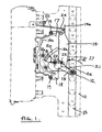
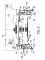
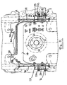
- Figures 1, 2 and 3
- show side, end and plan views respectively of a PTO shaft guard arrangement in accordance with the present invention in its retracted position, and
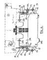
- Figures 4, 5 and 6
- show side, end and plan views respectively of the guard arrangement of
Figures 1 to 3 in its extended position, and - Figures 7, 8, 9, 10 and 11
- show perspective views of PTO guards in accordance with the present invention.
- According to
figures 1 to 6 , the rear of atractor chassis 10 is provided with a PTO shaft 11 which emerges from the chassis between two verticalhitch support plates 12, each provided with a vertically extendingslot 13 in which a vertically moveable hitch (not shown) is slideable. - A PTO
guard member 14 is pivotally mounted on theplates 12 by twoarms 15 which are screwed to the guard at 15a and which pivot aboutpins 16 screwed into theplates 12. Eachvertical plate 12 has a cut-out 17 to save weight which is covered by aside protection plate 18 secured to the adjacentvertical plate 12 bybolts 19. Eachprotection plate 18 has aslot 20 through which therespective support arm 15 for thePTO shaft cover 14 extends. - A
bow spring 21 acts between apin 22 on thesupport arm 15 and apin 23 mounted on the adjacentvertical plate 12. - A
top protection plate 24 is bolted on the rear of the chassis at 25 and extends between theedge portion 14a of the guard and the chassis when the guard is in its extended position shown inFigure 4 . - With the
PTO shaft guard 14 in its retracted position shown inFigure 1 , thebow spring 21 applies force to theguard 14 in the direction of the arrow A resulting in a turning moment on the guard in an anti-clockwise sense as shown by the arrow R thus holding the guard in its fully retracted position shown inFigure 1 . The lower end of theslot 20 in eachprotection plate 18 provides a stop for the downward movement ofarm 15. -
Figure 4 shows the PTO shaft guard in its fully extended position which thebow spring 21 applies a force B to the guard which generates a clockwise turning moment about theaxis 16 thus tending to hold the guard in its fully extended position. The clockwise movement of thearm 15 is limited by the edge 12a of theplate 12. - The
guard 14 has atab 14b allowing the operator to easily grip the guard for moving the guard between its retracted and extended position. As will be appreciated, thebow springs 21 initially oppose the movement of the guard from its current retracted or extended position, but when thepins 21 cross thelines 26 between thepivots 16 and thepins 23, the spring go "over centre" and assist in moving the guard towards its new position. - As can be seen from
Figure 4 , the front edge of theguard 14 hascam surfaces 27 which extends across thevertical slots 13 in thevertical plates 12. If a vertically moveable hitch is mounted in theslots 12 and is moved upwardly it will contact thiscam surfaces 27 and move the PTO guard towards its retracted position. Initially this movement will be opposed by thebow springs 21 but after themounting pins 22 move "over centre" this spring force will assist in retracting the PTO guard. -
Figures 7 to 11 show different arrangements of theshaft guard 14 according to the invention. The PTO shaft andhitch support plates 12 are not shown in these drawings. All other features, where present are indicated using the same reference numbers as infigures 1 to 6 . -
Figure 7 shows a perspective view of theguard 14 from the front as it would be viewed if attached to a vehicle having a PTO shaft. Theguard 14 has twoside portions 40 and acentral portion 41 which form a generally flat bottomed inverted U-shape.Figure 8 shows a perspective view of the guard in whichside portions 40 are fitted with releasably attachableadapter side members 42. Theadapter side members 42 protrude inwards towards each other and are attached toside portions 40 by fastening means such as bolts, or screws. The attachment means can be seen infigure 9 which show a perspective view of the back of the guard offigure 8 . The adapter side members decrease the distance of theside portions 40 of the guard from the PTO shaft. By fitting theadapter side members 42 greater space either side of the shaft is protected. -
Figures 10 and11 show front and rear perspective views of theguard 14 in which bothside 40 portions and thecentral portion 41 of theguard 14 are provided with releasably attachableside adapter members 42 and a centralportion adapter member 43. The centralportion adapter member 43 protrudes downwards towards a PTO shaft (not shown) and provides greater protection of the space between thecentral portion 41 and the PTO shaft. The centralportion adapter member 43 is attached to theguard 14, for example by bolts, or screws as can be seen fromfigure 11 which is a rear perspective view offigure 10 . The central portion adapted 43 andside portion members 42 may be individual parts, or a single piece. Theadapter side members 42 and centralpotion adapter member 43 alter the size of the guard which may be necessary to comply with certain rules and regulations in various countries.
Claims (8)
- A PTO shaft guard arrangement in which a guard member (14) is of inverted U-shaped form and is pivotally mounted on a support structure the arrangement being characterised in that the support structure comprises a pair of generally vertically extending plates (12) located on opposite sides of the associated PTO shaft (11) between which the guard member (14) is pivotally mounted for movement between a non-operative retracted position and an operative extended position, the guard member having an over-centre spring means (21) for holding the guard member in both the retracted and extended positions.
- An arrangement according to claim 1 characterised in that each side of the guard member (14) is mounted on its respective generally vertically extending plate (12) via a support arm (15) one end portion (16) of which is pivoted on the plate, the other end portion (15a) of the arm being connected with the respective side of the guard.
- An arrangement according to claim 2 characterised in that the spring means comprises a pair of bow springs (21), one end (23) of each bow spring being mounted on the adjacent generally vertically extending plate (12) and the other end (22) being mounted on the adjacent support arm (15).
- An arrangement according to any one of claims 1 to 3 characterised in that each generally vertically extending plate (12) includes a generally vertically extending slot (13), a towing hitch being vertically slidable between the plates in the slots and lockable relative to the plates at various heights.
- An arrangement according to claim 4 characterised in that as the hitch is moved vertically into the vicinity of the PTO shaft (11), if the guard member (14) is in the extended position, the hitch contacts the guard and moves the guard towards the retracted position.
- An arrangement according to any one of claims 2 to 5 in which PTO shaft fixed side protection plates (18) extend between the vertically extending plates (12) and the tractor chassis on which the vertically extending plates are mounted, each support arm (15) moving in a slot (20) provided in its respective side protection plate (18).
- An arrangement according to claim 6 in which a fixed top protection plate (24) extends between the tractor chassis and an inner edge of the top of the guard member (14) when the guard member is in its extended position.
- An arrangement according to any preceding claim wherein the guard member (14) is provided with at least one releasably attachable adapter member (42) which decreases the distance between the guard (14) and the PTO shaft (11).
Applications Claiming Priority (2)
| Application Number | Priority Date | Filing Date | Title |
|---|---|---|---|
| GBGB0811909.1A GB0811909D0 (en) | 2008-07-01 | 2008-07-01 | Power take-off shaft guards |
| PCT/EP2009/057782 WO2010000642A1 (en) | 2008-07-01 | 2009-06-23 | Power take-off shaft guards |
Publications (2)
| Publication Number | Publication Date |
|---|---|
| EP2309836A1 EP2309836A1 (en) | 2011-04-20 |
| EP2309836B1 true EP2309836B1 (en) | 2012-03-07 |
Family
ID=39683360
Family Applications (1)
| Application Number | Title | Priority Date | Filing Date |
|---|---|---|---|
| EP09772342A Active EP2309836B1 (en) | 2008-07-01 | 2009-06-23 | Power take-off shaft guards |
Country Status (4)
| Country | Link |
|---|---|
| EP (1) | EP2309836B1 (en) |
| AT (1) | ATE547933T1 (en) |
| GB (1) | GB0811909D0 (en) |
| WO (1) | WO2010000642A1 (en) |
Cited By (1)
| Publication number | Priority date | Publication date | Assignee | Title |
|---|---|---|---|---|
| EP4681579A2 (en) | 2024-07-15 | 2026-01-21 | Wanzl GmbH & Co. KGaA | Shelf board for a merchandise shelf |
Family Cites Families (4)
| Publication number | Priority date | Publication date | Assignee | Title |
|---|---|---|---|---|
| DE2745628C3 (en) * | 1977-10-11 | 1980-04-24 | Jean Walterscheid Gmbh, 5204 Lohmar | Device for coupling and uncoupling a cardan shaft |
| DE3402065C1 (en) * | 1984-01-21 | 1985-04-18 | Deere & Co., Moline, Ill., US, Niederlassung Deere & Co. European Office, 6800 Mannheim | Protective device to prevent contact with at least one rotating part |
| US4840604A (en) * | 1988-05-26 | 1989-06-20 | Deere & Company | Master safety shield with deflecting door |
| DE10222005B4 (en) * | 2002-05-17 | 2005-04-21 | Fritz Sperber Gmbh & Co. | Protective device for the end of the PTO shaft of a tractor |
-
2008
- 2008-07-01 GB GBGB0811909.1A patent/GB0811909D0/en not_active Ceased
-
2009
- 2009-06-23 EP EP09772342A patent/EP2309836B1/en active Active
- 2009-06-23 WO PCT/EP2009/057782 patent/WO2010000642A1/en not_active Ceased
- 2009-06-23 AT AT09772342T patent/ATE547933T1/en active
Cited By (1)
| Publication number | Priority date | Publication date | Assignee | Title |
|---|---|---|---|---|
| EP4681579A2 (en) | 2024-07-15 | 2026-01-21 | Wanzl GmbH & Co. KGaA | Shelf board for a merchandise shelf |
Also Published As
| Publication number | Publication date |
|---|---|
| WO2010000642A1 (en) | 2010-01-07 |
| EP2309836A1 (en) | 2011-04-20 |
| ATE547933T1 (en) | 2012-03-15 |
| GB0811909D0 (en) | 2008-07-30 |
Similar Documents
| Publication | Publication Date | Title |
|---|---|---|
| EP1538888B1 (en) | Upper hitch link | |
| US20230278515A1 (en) | Quick Release Grill Guard And Associated Systems And Methods | |
| US11220303B2 (en) | Swingable vehicle accessory mount assembly | |
| US11702014B2 (en) | Swingable vehicle accessory mount assembly | |
| US5839758A (en) | Roll-over protective system for tractors | |
| US8523225B2 (en) | Overhead frame structure system | |
| CA1147376A (en) | Vehicle access ladder | |
| EP2073998B1 (en) | Roll-over protection system | |
| US4553950A (en) | Flip-up shield assembly for tractor power take-off | |
| AU2013235771B2 (en) | Automatic lock system for vehicle hitch assembly | |
| US9579994B2 (en) | Adjustable seat support | |
| EP2309836A1 (en) | Power take-off shaft guards | |
| KR101488369B1 (en) | Mounting structure of fender side cover | |
| EP2140748B1 (en) | Tractor hitches | |
| EP3638569B1 (en) | A locking mechanism for a rotating mudguard assembly | |
| EP2052903B1 (en) | Folding seats | |
| EP2790483B1 (en) | Link holder on a vehicle or machine | |
| JP2017165250A (en) | Passenger work vehicle | |
| US8371601B2 (en) | Fifth wheel slide assembly secondary lock | |
| US10710420B2 (en) | Jackknife prevention device | |
| JPH05213126A (en) | Front grill guard | |
| EP4000363B1 (en) | Agricultural tractor with additional axle | |
| EP2815928B1 (en) | Bumper end portion and bumper fitted bumper end parts and tractor fitted with the bumper | |
| CA2946491C (en) | Releasable lock for rear folding implement wings | |
| JPH04148800A (en) | Reach cylinder fitting construction for reach type fork lift |
Legal Events
| Date | Code | Title | Description |
|---|---|---|---|
| PUAI | Public reference made under article 153(3) epc to a published international application that has entered the european phase |
Free format text: ORIGINAL CODE: 0009012 |
|
| 17P | Request for examination filed |
Effective date: 20110201 |
|
| AK | Designated contracting states |
Kind code of ref document: A1 Designated state(s): AT BE BG CH CY CZ DE DK EE ES FI FR GB GR HR HU IE IS IT LI LT LU LV MC MK MT NL NO PL PT RO SE SI SK TR |
|
| AX | Request for extension of the european patent |
Extension state: AL BA RS |
|
| DAX | Request for extension of the european patent (deleted) | ||
| GRAP | Despatch of communication of intention to grant a patent |
Free format text: ORIGINAL CODE: EPIDOSNIGR1 |
|
| GRAS | Grant fee paid |
Free format text: ORIGINAL CODE: EPIDOSNIGR3 |
|
| GRAA | (expected) grant |
Free format text: ORIGINAL CODE: 0009210 |
|
| AK | Designated contracting states |
Kind code of ref document: B1 Designated state(s): AT BE BG CH CY CZ DE DK EE ES FI FR GB GR HR HU IE IS IT LI LT LU LV MC MK MT NL NO PL PT RO SE SI SK TR |
|
| REG | Reference to a national code |
Ref country code: GB Ref legal event code: FG4D |
|
| REG | Reference to a national code |
Ref country code: CH Ref legal event code: EP Ref country code: AT Ref legal event code: REF Ref document number: 547933 Country of ref document: AT Kind code of ref document: T Effective date: 20120315 |
|
| REG | Reference to a national code |
Ref country code: IE Ref legal event code: FG4D |
|
| REG | Reference to a national code |
Ref country code: DE Ref legal event code: R096 Ref document number: 602009005803 Country of ref document: DE Effective date: 20120503 |
|
| REG | Reference to a national code |
Ref country code: NL Ref legal event code: VDEP Effective date: 20120307 |
|
| PG25 | Lapsed in a contracting state [announced via postgrant information from national office to epo] |
Ref country code: NL Free format text: LAPSE BECAUSE OF FAILURE TO SUBMIT A TRANSLATION OF THE DESCRIPTION OR TO PAY THE FEE WITHIN THE PRESCRIBED TIME-LIMIT Effective date: 20120307 Ref country code: LT Free format text: LAPSE BECAUSE OF FAILURE TO SUBMIT A TRANSLATION OF THE DESCRIPTION OR TO PAY THE FEE WITHIN THE PRESCRIBED TIME-LIMIT Effective date: 20120307 Ref country code: HR Free format text: LAPSE BECAUSE OF FAILURE TO SUBMIT A TRANSLATION OF THE DESCRIPTION OR TO PAY THE FEE WITHIN THE PRESCRIBED TIME-LIMIT Effective date: 20120307 Ref country code: NO Free format text: LAPSE BECAUSE OF FAILURE TO SUBMIT A TRANSLATION OF THE DESCRIPTION OR TO PAY THE FEE WITHIN THE PRESCRIBED TIME-LIMIT Effective date: 20120607 |
|
| LTIE | Lt: invalidation of european patent or patent extension |
Effective date: 20120307 |
|
| PG25 | Lapsed in a contracting state [announced via postgrant information from national office to epo] |
Ref country code: FI Free format text: LAPSE BECAUSE OF FAILURE TO SUBMIT A TRANSLATION OF THE DESCRIPTION OR TO PAY THE FEE WITHIN THE PRESCRIBED TIME-LIMIT Effective date: 20120307 Ref country code: LV Free format text: LAPSE BECAUSE OF FAILURE TO SUBMIT A TRANSLATION OF THE DESCRIPTION OR TO PAY THE FEE WITHIN THE PRESCRIBED TIME-LIMIT Effective date: 20120307 Ref country code: GR Free format text: LAPSE BECAUSE OF FAILURE TO SUBMIT A TRANSLATION OF THE DESCRIPTION OR TO PAY THE FEE WITHIN THE PRESCRIBED TIME-LIMIT Effective date: 20120608 |
|
| REG | Reference to a national code |
Ref country code: AT Ref legal event code: MK05 Ref document number: 547933 Country of ref document: AT Kind code of ref document: T Effective date: 20120307 |
|
| PG25 | Lapsed in a contracting state [announced via postgrant information from national office to epo] |
Ref country code: CY Free format text: LAPSE BECAUSE OF FAILURE TO SUBMIT A TRANSLATION OF THE DESCRIPTION OR TO PAY THE FEE WITHIN THE PRESCRIBED TIME-LIMIT Effective date: 20120307 |
|
| PG25 | Lapsed in a contracting state [announced via postgrant information from national office to epo] |
Ref country code: EE Free format text: LAPSE BECAUSE OF FAILURE TO SUBMIT A TRANSLATION OF THE DESCRIPTION OR TO PAY THE FEE WITHIN THE PRESCRIBED TIME-LIMIT Effective date: 20120307 Ref country code: RO Free format text: LAPSE BECAUSE OF FAILURE TO SUBMIT A TRANSLATION OF THE DESCRIPTION OR TO PAY THE FEE WITHIN THE PRESCRIBED TIME-LIMIT Effective date: 20120307 Ref country code: PL Free format text: LAPSE BECAUSE OF FAILURE TO SUBMIT A TRANSLATION OF THE DESCRIPTION OR TO PAY THE FEE WITHIN THE PRESCRIBED TIME-LIMIT Effective date: 20120307 Ref country code: CZ Free format text: LAPSE BECAUSE OF FAILURE TO SUBMIT A TRANSLATION OF THE DESCRIPTION OR TO PAY THE FEE WITHIN THE PRESCRIBED TIME-LIMIT Effective date: 20120307 Ref country code: SE Free format text: LAPSE BECAUSE OF FAILURE TO SUBMIT A TRANSLATION OF THE DESCRIPTION OR TO PAY THE FEE WITHIN THE PRESCRIBED TIME-LIMIT Effective date: 20120307 Ref country code: IS Free format text: LAPSE BECAUSE OF FAILURE TO SUBMIT A TRANSLATION OF THE DESCRIPTION OR TO PAY THE FEE WITHIN THE PRESCRIBED TIME-LIMIT Effective date: 20120707 Ref country code: BE Free format text: LAPSE BECAUSE OF FAILURE TO SUBMIT A TRANSLATION OF THE DESCRIPTION OR TO PAY THE FEE WITHIN THE PRESCRIBED TIME-LIMIT Effective date: 20120307 Ref country code: SI Free format text: LAPSE BECAUSE OF FAILURE TO SUBMIT A TRANSLATION OF THE DESCRIPTION OR TO PAY THE FEE WITHIN THE PRESCRIBED TIME-LIMIT Effective date: 20120307 |
|
| PG25 | Lapsed in a contracting state [announced via postgrant information from national office to epo] |
Ref country code: PT Free format text: LAPSE BECAUSE OF FAILURE TO SUBMIT A TRANSLATION OF THE DESCRIPTION OR TO PAY THE FEE WITHIN THE PRESCRIBED TIME-LIMIT Effective date: 20120709 Ref country code: SK Free format text: LAPSE BECAUSE OF FAILURE TO SUBMIT A TRANSLATION OF THE DESCRIPTION OR TO PAY THE FEE WITHIN THE PRESCRIBED TIME-LIMIT Effective date: 20120307 |
|
| PLBE | No opposition filed within time limit |
Free format text: ORIGINAL CODE: 0009261 |
|
| STAA | Information on the status of an ep patent application or granted ep patent |
Free format text: STATUS: NO OPPOSITION FILED WITHIN TIME LIMIT |
|
| PG25 | Lapsed in a contracting state [announced via postgrant information from national office to epo] |
Ref country code: DK Free format text: LAPSE BECAUSE OF FAILURE TO SUBMIT A TRANSLATION OF THE DESCRIPTION OR TO PAY THE FEE WITHIN THE PRESCRIBED TIME-LIMIT Effective date: 20120307 Ref country code: AT Free format text: LAPSE BECAUSE OF FAILURE TO SUBMIT A TRANSLATION OF THE DESCRIPTION OR TO PAY THE FEE WITHIN THE PRESCRIBED TIME-LIMIT Effective date: 20120307 Ref country code: MC Free format text: LAPSE BECAUSE OF NON-PAYMENT OF DUE FEES Effective date: 20120630 |
|
| 26N | No opposition filed |
Effective date: 20121210 |
|
| PG25 | Lapsed in a contracting state [announced via postgrant information from national office to epo] |
Ref country code: MK Free format text: LAPSE BECAUSE OF FAILURE TO SUBMIT A TRANSLATION OF THE DESCRIPTION OR TO PAY THE FEE WITHIN THE PRESCRIBED TIME-LIMIT Effective date: 20120307 |
|
| REG | Reference to a national code |
Ref country code: IE Ref legal event code: MM4A |
|
| REG | Reference to a national code |
Ref country code: DE Ref legal event code: R097 Ref document number: 602009005803 Country of ref document: DE Effective date: 20121210 |
|
| PG25 | Lapsed in a contracting state [announced via postgrant information from national office to epo] |
Ref country code: ES Free format text: LAPSE BECAUSE OF FAILURE TO SUBMIT A TRANSLATION OF THE DESCRIPTION OR TO PAY THE FEE WITHIN THE PRESCRIBED TIME-LIMIT Effective date: 20120618 Ref country code: IE Free format text: LAPSE BECAUSE OF NON-PAYMENT OF DUE FEES Effective date: 20120623 |
|
| PG25 | Lapsed in a contracting state [announced via postgrant information from national office to epo] |
Ref country code: MT Free format text: LAPSE BECAUSE OF FAILURE TO SUBMIT A TRANSLATION OF THE DESCRIPTION OR TO PAY THE FEE WITHIN THE PRESCRIBED TIME-LIMIT Effective date: 20120307 Ref country code: BG Free format text: LAPSE BECAUSE OF FAILURE TO SUBMIT A TRANSLATION OF THE DESCRIPTION OR TO PAY THE FEE WITHIN THE PRESCRIBED TIME-LIMIT Effective date: 20120607 |
|
| REG | Reference to a national code |
Ref country code: CH Ref legal event code: PL |
|
| PG25 | Lapsed in a contracting state [announced via postgrant information from national office to epo] |
Ref country code: LI Free format text: LAPSE BECAUSE OF NON-PAYMENT OF DUE FEES Effective date: 20130630 Ref country code: TR Free format text: LAPSE BECAUSE OF FAILURE TO SUBMIT A TRANSLATION OF THE DESCRIPTION OR TO PAY THE FEE WITHIN THE PRESCRIBED TIME-LIMIT Effective date: 20120307 Ref country code: CH Free format text: LAPSE BECAUSE OF NON-PAYMENT OF DUE FEES Effective date: 20130630 |
|
| PG25 | Lapsed in a contracting state [announced via postgrant information from national office to epo] |
Ref country code: LU Free format text: LAPSE BECAUSE OF NON-PAYMENT OF DUE FEES Effective date: 20120623 |
|
| PG25 | Lapsed in a contracting state [announced via postgrant information from national office to epo] |
Ref country code: HU Free format text: LAPSE BECAUSE OF FAILURE TO SUBMIT A TRANSLATION OF THE DESCRIPTION OR TO PAY THE FEE WITHIN THE PRESCRIBED TIME-LIMIT Effective date: 20090623 |
|
| REG | Reference to a national code |
Ref country code: FR Ref legal event code: PLFP Year of fee payment: 8 |
|
| REG | Reference to a national code |
Ref country code: FR Ref legal event code: PLFP Year of fee payment: 9 |
|
| PGFP | Annual fee paid to national office [announced via postgrant information from national office to epo] |
Ref country code: GB Payment date: 20170620 Year of fee payment: 9 |
|
| PGFP | Annual fee paid to national office [announced via postgrant information from national office to epo] |
Ref country code: IT Payment date: 20170626 Year of fee payment: 9 |
|
| REG | Reference to a national code |
Ref country code: FR Ref legal event code: PLFP Year of fee payment: 10 |
|
| GBPC | Gb: european patent ceased through non-payment of renewal fee |
Effective date: 20180623 |
|
| PG25 | Lapsed in a contracting state [announced via postgrant information from national office to epo] |
Ref country code: IT Free format text: LAPSE BECAUSE OF NON-PAYMENT OF DUE FEES Effective date: 20180623 Ref country code: GB Free format text: LAPSE BECAUSE OF NON-PAYMENT OF DUE FEES Effective date: 20180623 |
|
| P01 | Opt-out of the competence of the unified patent court (upc) registered |
Effective date: 20230518 |
|
| PGFP | Annual fee paid to national office [announced via postgrant information from national office to epo] |
Ref country code: DE Payment date: 20250618 Year of fee payment: 17 |
|
| PGFP | Annual fee paid to national office [announced via postgrant information from national office to epo] |
Ref country code: FR Payment date: 20250624 Year of fee payment: 17 |