EP2309782A1 - Wireless communication device and wireless communication method - Google Patents
Wireless communication device and wireless communication method Download PDFInfo
- Publication number
- EP2309782A1 EP2309782A1 EP08778179A EP08778179A EP2309782A1 EP 2309782 A1 EP2309782 A1 EP 2309782A1 EP 08778179 A EP08778179 A EP 08778179A EP 08778179 A EP08778179 A EP 08778179A EP 2309782 A1 EP2309782 A1 EP 2309782A1
- Authority
- EP
- European Patent Office
- Prior art keywords
- signal
- wireless communication
- data
- frame
- wireless
- Prior art date
- Legal status (The legal status is an assumption and is not a legal conclusion. Google has not performed a legal analysis and makes no representation as to the accuracy of the status listed.)
- Withdrawn
Links
Images


Classifications
-
- H—ELECTRICITY
- H04—ELECTRIC COMMUNICATION TECHNIQUE
- H04W—WIRELESS COMMUNICATION NETWORKS
- H04W72/00—Local resource management
- H04W72/50—Allocation or scheduling criteria for wireless resources
- H04W72/54—Allocation or scheduling criteria for wireless resources based on quality criteria
- H04W72/541—Allocation or scheduling criteria for wireless resources based on quality criteria using the level of interference
-
- H—ELECTRICITY
- H04—ELECTRIC COMMUNICATION TECHNIQUE
- H04L—TRANSMISSION OF DIGITAL INFORMATION, e.g. TELEGRAPHIC COMMUNICATION
- H04L1/00—Arrangements for detecting or preventing errors in the information received
- H04L1/0001—Systems modifying transmission characteristics according to link quality, e.g. power backoff
- H04L1/0023—Systems modifying transmission characteristics according to link quality, e.g. power backoff characterised by the signalling
- H04L1/0026—Transmission of channel quality indication
-
- H—ELECTRICITY
- H04—ELECTRIC COMMUNICATION TECHNIQUE
- H04L—TRANSMISSION OF DIGITAL INFORMATION, e.g. TELEGRAPHIC COMMUNICATION
- H04L1/00—Arrangements for detecting or preventing errors in the information received
- H04L1/12—Arrangements for detecting or preventing errors in the information received by using return channel
- H04L1/16—Arrangements for detecting or preventing errors in the information received by using return channel in which the return channel carries supervisory signals, e.g. repetition request signals
- H04L1/18—Automatic repetition systems, e.g. Van Duuren systems
- H04L1/1829—Arrangements specially adapted for the receiver end
- H04L1/1854—Scheduling and prioritising arrangements
-
- H—ELECTRICITY
- H04—ELECTRIC COMMUNICATION TECHNIQUE
- H04W—WIRELESS COMMUNICATION NETWORKS
- H04W16/00—Network planning, e.g. coverage or traffic planning tools; Network deployment, e.g. resource partitioning or cells structures
- H04W16/14—Spectrum sharing arrangements between different networks
-
- H—ELECTRICITY
- H04—ELECTRIC COMMUNICATION TECHNIQUE
- H04W—WIRELESS COMMUNICATION NETWORKS
- H04W48/00—Access restriction; Network selection; Access point selection
- H04W48/18—Selecting a network or a communication service
-
- H—ELECTRICITY
- H04—ELECTRIC COMMUNICATION TECHNIQUE
- H04W—WIRELESS COMMUNICATION NETWORKS
- H04W72/00—Local resource management
- H04W72/12—Wireless traffic scheduling
- H04W72/1215—Wireless traffic scheduling for collaboration of different radio technologies
-
- H—ELECTRICITY
- H04—ELECTRIC COMMUNICATION TECHNIQUE
- H04L—TRANSMISSION OF DIGITAL INFORMATION, e.g. TELEGRAPHIC COMMUNICATION
- H04L5/00—Arrangements affording multiple use of the transmission path
- H04L5/0001—Arrangements for dividing the transmission path
- H04L5/0003—Two-dimensional division
- H04L5/0005—Time-frequency
- H04L5/0007—Time-frequency the frequencies being orthogonal, e.g. OFDM(A) or DMT
-
- H—ELECTRICITY
- H04—ELECTRIC COMMUNICATION TECHNIQUE
- H04W—WIRELESS COMMUNICATION NETWORKS
- H04W72/00—Local resource management
- H04W72/04—Wireless resource allocation
-
- H—ELECTRICITY
- H04—ELECTRIC COMMUNICATION TECHNIQUE
- H04W—WIRELESS COMMUNICATION NETWORKS
- H04W84/00—Network topologies
- H04W84/18—Self-organising networks, e.g. ad-hoc networks or sensor networks
-
- H—ELECTRICITY
- H04—ELECTRIC COMMUNICATION TECHNIQUE
- H04W—WIRELESS COMMUNICATION NETWORKS
- H04W88/00—Devices specially adapted for wireless communication networks, e.g. terminals, base stations or access point devices
- H04W88/02—Terminal devices
- H04W88/06—Terminal devices adapted for operation in multiple networks or having at least two operational modes, e.g. multi-mode terminals
Definitions
- the present invention relates to a wireless communication apparatus and a method for wireless communication that conform to a number of different wireless communication systems.
- WiMAX Worldwide interoperability for Microwave Access
- WiMAX is one of wireless broadband communication systems being standardized in the IEEE (Institute of Electrical and Electronic Engineers).
- a function of a short distance wireless communication system such as Bluetooth (R) or WLAN (Wireless Local Aria Network)
- WiMAX makes the mobile terminal to solely perform a variety of functions.
- the frequency band of WiMAX and the frequency of Bluetooth or WLAN overlap around 2.4 GHz.
- the same frequency is competitively used by a number of communication systems. For this reason, if a mobile terminal which supports both communication of WiMAX and communication of Bluetooth or WLAN carries out the both communication at the same time through the overlapping frequency, one of communications interferes with the other communication, which may be a cause of lowering the throughput.
- one of effective solutions is to control timings of data transmission and data reception of respective communication systems so as not to overlap by allocating a wireless resource to respective communication systems through the TDM (Time Division Multiplexing) scheme.
- TDM Time Division Multiplexing
- Patent Literature 1 describes a technique of, in a mobile terminal which can transmit and receive signals of a communication system (hereinafter sometimes called WiMAX system) of WiMAX and signals of a communication system (hereinafter sometimes called Bluetooth system) of Bluetooth, transmitting and receiving the signals of the Bluetooth system at a frame timing while the WiMAX system is in a sleep mode.
- WiMAX system a communication system
- Bluetooth system a communication system
- the base station In a wireless communication system which carries out data transmission and data reception through the use of wireless frames synchronized with a base station, the base station intensively controls allocation of wireless resource.
- a mobile terminal confirming to a number of communication systems independently decides to release a wireless resource allocated to transmission of one of the communication systems and to use the released resource for transmission of another one of communication without negotiation with the base station.
- the base station controls allocation of the wireless resource to a mobile terminal communicable through a number of communication systems using the same wireless resource (e.g., frequency) through the use of the TDM scheme or the like such that timings of signal transmission and receiving of the respective communication system overlap.
- the base station negotiates with each individual mobile terminal and controls the above allocation of the wireless resource to the individual mobile terminal.
- the object of the embodiment to be discussed herein is to lower possible interference in a different approach from the conventional techniques.
- a wireless communication apparatus including: a first signal communicating unit that receives a first signal of a first wireless communication system or transmits, based on allocation information of a wireless communication resource which information is transmitted in a predetermined cycle, the first signal of the first wireless communication system; a second signal communicating unit that receives or transmits a second signal of a second wireless communication system different from the first wireless communication system; and a controller that restricts the first signal communicating unit to transmit the first signal of the first wireless communication system using a wireless communication resource allocated by the allocation information while the second signal communicating unit transmits or receives the second signal.
- WiMAX adopts a communication scheme based on Orthogonal Frequency Division Multiplexing (OFDMA).
- OFDMA Orthogonal Frequency Division Multiplexing
- a WiMAX system of the first embodiment uses wireless frames defined in terms of the time axis segmented by OFDMA symbol time and the frequency axis segmented by sub-channel (logical set of orthogonal sub-carriers).
- the base station segments the time domain of a sub-channel shared by mobile terminals, serving as examples of wireless communication apparatus, in units of OFDMA symbol number and then dynamically allocates the segmented sub-channel to respective mobile terminals.
- FDD Frequency Division Duplex
- TDD Time Division Duplex
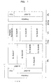
- Fig. 1 illustrates an example of the format of a TDD-scheme wireless frame used in the WiMAX system.
- the abscissa represents time (t); the ordinate represents frequency (f); DL represents a DL sub-frame used in downlink communication; and UL represents a UL sub-frame used in uplink communication.
- TTG Transmit / Receive Transition Gap
- RTG Receiveive / Transmit Transition Gap
- the preamble in the front of the DL sub-frame is used by each mobile terminal that transmits and receives signals to and from a base station for synchronize with the base station.
- FCH represents Frame Control Header including information to specify the modulation scheme and the coding scheme of the MAP information (DL-MAP, UL-MAP).
- DL-MAP is allocation information of DL Burst (frequency, timing) serving an example of the wireless resource
- UL-MAP is allocation information of UL Burst (frequency, timing) serving an example of the wireless resource.
- DL Burst and UL Burst is a DL data transmitting region and an UL data transmitting region, respectively.
- the allocation information (Burst Profile) of DL-MAP and that of the UL-MAP include mapping information and information about data transmitting schemes of the Bursts in the DL sub-frames and the UL sub-frames, respectively. Accordingly, the mobile terminal receives data in a region of the DL Burst indicated by the DL-MAP and transmits data to the base station in a region of the UL Burst indicated by the UL-MAP.
- the allocation information of the UL-MAP may represent allocation of the UL burst at the N-th frame (N is a natural number) or allocation of the UL Burst at the (N+1)-th frame (or a subsequent frame).
- Ranging Sub-channel is a transmitting region of a CDMA (Code Division Mutiple(sic)) Access) ranging code to be used for ranging to adjust timing and transmitting electric power level when the mobile terminal is establishing a connection to the base station.
- CDMA Code Division Mutiple(sic)
- Allocation of the wireless resource is accomplished by the mobile terminal transmitting a signal requesting a band through which the mobile terminal communicates and the base station mapping based on the information included in the request signal.
- the WiMAX system includes a function of controlling retransmission of data by means of Automatic Repeat Request (ARQ) in a MAC (Medium Access Control) layer.
- ARQ Automatic Repeat Request
- a receiver of data detects an error in received data through the use of redundant bits for error detection that the data transmitter attached to each data unit. If the receiver detects an error in the received data or does not receive the data, the receiver transmits a signal (NACK signal) that requests the transmitter to retransmit, to the transmitter, the data in which the error has been detected or the data cannot be received by the receiver. Upon receipt of the NACK signal, the transmitter retransmits the data for which retransmission has been requested. If no error is detected in the received data, the receiver transmits a signal (ACK signal) notifying successful reception to the transmitter. In response to receipt of the ACK signal, the transmitter transmits another data to the receiver.
- NACK signal a signal that requests the transmitter to retransmit, to the transmitter, the data in which the error has been detected or the data cannot be received by the receiver.
- the transmitter Upon receipt of the NACK signal, the transmitter retransmits the data for which retransmission has been requested. If no error is detected in the received data, the
- the above function of controlling retransmission makes it possible to improve the reliability of data communication.
- Bluetooth carries out bidirectional communication of data between a master and a slave, which carries out communication under the control of the master, via TDD scheme.
- one second (s) is divided into 1,600 time slots (625 ⁇ s per time slot), and the time slots are allocated time slot numbers ts0, ts1, ts2, ....
- the master transmits data to the slave during, for example, even time slots while the slave transmits data to the master during odd time slots.
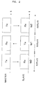
- Fig. 2 illustrates an example of time slot used in the Bluetooth system.
- Tx and Rx represent transmitting data and received data.
- the master transmits data during time slots ts0 and ts2 while the slave transmits data during time slot ts1.
- the master and the slave are independently of each other capable of frequency hopping, that is, varying the transmitting frequency for each data transmission.
- Time slot may be a single slot in units of one slot (625 ⁇ s) and a multi slot in units of a number of slots, such as three slots (1,875 ⁇ s) or five slots (3,125 ⁇ s).
- data communication is carried out at the same frequency throughout one slot; and in a multi slot, data communication is carried out at the same frequency throughout three or five slots.
- timing is adjusted by a clock (counter) installed in a terminal having a Bluetooth communication function.
- the master and the slave are synchronized with each other by calculating an offset of clock values of the master and the slave and adding the offset to either clock value.
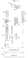
- Fig. 3 illustrates an example of operation performed in the first embodiment.
- description will now be made in relation to operation of a mobile terminal which is equipped with a communication function of the WiMAX system (first wireless communication system) and a communication function of the Bluetooth system (second wireless communication system) and to which the first embodiment is applied.
- WiMAX BS Base Station
- WiMAX MS Mobile Station
- WiMAX frame represents a wireless frame of the WiMAX system.
- DL sub-frame represents a DL sub-frame.
- UL sub-frame represents a UL sub-frame.
- a set of a DL sub-frame and a UL sub-frame is regarded as one frame and three frames are a TDM controlling cycle.
- the first, the second, and the third frame in a single TDM controlling cycle are simply called the first frame, the second frame, and the third frame, respectively.
- Bluetooth PA (Power Amp) Enable represents time period during which the amplifier, such as a power amplifier, included in a transmitting circuit in the Bluetooth system is enable or disable.
- a period during which data transmission and reception of the WiMAX system is restricted and during which concurrently the Bluetooth is provided with an opportunity for communication is defined as a Non-interfering period.
- the amplifier is enabled during the Non-interfering period while is disabled during period except the Non-interfering period.
- data transmission of the Bluetooth system is restricted.
- the terms "restrict” and “restriction” mean transmission and receiving processing is stopped or limited (inhibited).
- the processing of "limiting (inhibiting)" includes, for example, lowering the transmitting power, that is, signal transmitting is continued under a state of lowering the transmission power to an extent that occurs no interference.
- the Non-interfering period is set in the first frame of the TDM controlling cycle.
- Bluetooth Slot represents time slots of the Bluetooth.
- Tx represents a time slot for data transmission;
- Rx represents a time slot for data reception; and
- Op represents an optional time slot during which data can be transmitted and received.
- a time slot with a cross (x) represents a time slot which is not included in the Non-interfering period and during which data transmission is inhibited.
- the Non-interfering period is set in the mobile terminal, and during the Non-interfering period, the amplifier included in the transmitting circuit of the Bluetooth system is enabled so that the data is transmitted in the Bluetooth system.
- the Non-interfering period can be set so as not overlap with a period during which Map information, to be detailed below, in a DL sub-frame is transmitted from the base station to the mobile terminal.
- Map information to be detailed below
- This setting makes the mobile station possible to improve the ratio of success in receiving MAP information transmitted from the base station, concurrently suppressing interference caused by transmitting signals in the Bluetooth system.
- the base station transmits the MAP information to the mobile terminal (S1).
- the MAP information includes information about DL-MAP of the first frame, and UL-MAP information of the first or the second frame.
- the mobile terminal can obtain the allocation information of the communication region of the DL sub-frame or the UL sub-frame of the first frame.
- the base station transmits DL MAC-PDU (DownLink Medium Access Control layer-Protocol Data Unit) #1 destined for the mobile terminal through the DL Burst region of the DL sub-frame of the first frame (S2).
- DL MAC-PDU DownLink Medium Access Control layer-Protocol Data Unit
- the amplifier included in the transmitting circuit of the Bluetooth system is enabled, so that data is transmitted in the time slot Tx and data is received in the time slot Rx.
- the signal including DL MAC-PDU #1 transmitted from the base station may be subjected to interference with a Bluetooth signal transmitted at the time slot Tx. If the interference is large enough to damage the DL MAC-PDU #1, the mobile terminal detects an error in the data.
- the mobile terminal restricts (e.g., stops or limits transmitting processing) data transmission of the WiMAX system, and in turn, carries out data transmission of the Bluetooth system (S3).
- the restriction of data transmission of the WiMAX system in the mobile terminal is withdrawn when the Non-interfering period expires. In the example of Fig. 3 , the Non-interfering period expires at the end of the first frame. The timing of the withdrawal is satisfactory any time point before the mobile terminal receives the MAP information transmitted from the base station in the next transmission cycle.
- the terms of "withdraw” and “withdrawal” means that data transmission is started or lowered transmission electric power is regained.
- the amplifier included in the transmitting circuit of the Bluetooth system is disabled, so that the data transmission of the Bluetooth system is inhibited.
- the base station transmits MAP information about the DL sub-frame of the second frame and the UL sub-frames of the second and the third frames (S4).
- the MAP information includes the DL-MAP of the second frame and the UL-MAP of the second or the third frame.
- the base station If the base station detects that the base station does not receive the UL MAC-PDU #1 or failed in receiving the UL MAC-PDU#1 from the mobile terminal, the base station transmits a NACK signal for the UL MAC-PDU#1 through the DL sub-frame of the second frame to the mobile station in order to request retransmission of the data (S5). If the mobile terminal detects that the mobile terminal does not receive the DL MAC-PDU #1 or failed in receiving the DL MAC-PDU #1 from the base station, the mobile terminal transmits a NACK signal for the DL MAC-PDU#1 through the UL sub-frame of the second frame to the base station in order to request retransmission of the data (S6).
- an ACK signal is returned to the source that transmitted the data by means of the second frame. Due to some reason, such as processing load on the base station and/or the mobile station, NACK and ACK signals may be transmitted in the third frame or later.
- the base station transmits MAP information about the DL sub-frame and the UL sub-frame of the third frame to the mobile station (S7).
- the MAP information includes information about the DL-MAP of the third frame and UL-MAP of the third frame or the first frame of the next TDM controlling cycle.
- the base station If the base station receives the NACK signal through the UL sub-frame of the second frame, the base station transmits (retransmits) the DL MAC-PDU #1 to the mobile station through the DL sub-frame of the third frame (S8) in response to the reception of the NACK signal.
- the mobile terminal If the mobile station receives the NACK signal through the DL sub-frame of the second frame from the base station, the mobile terminal transmits (retransmits) the UL MAC-PDU #1 to the base station through the UL sub-frame of the third frame (S9) in response to the reception of the NACK signal.
- the above procedure makes the mobile terminal possible to correctly transmit or receive data of the WiMAX system, which data has not been correctly transmitted to or received from the base station during the Non-interfering period set in the first frame, in the third frame or later. Furthermore, during the Non-interfering period, data of the Bluetooth system can be transmitted and received in a state of inhibiting interference with signals of the WiMAX system, so that communication throughput of the Bluetooth system can be inhibited from lowering.
- the TDM controlling cycle is assumed to include three frames, but is not limited to three frames. Namely, a period set to be the Non-interfering period and a period set to control retransmission of data of the WiMAX system can be varied.
- the TDM controlling cycle may include a number of frames as many as the sum of the frames of the Non-interfering period and frames that affords to data retransmission control of the WiMAX system.
- the above example restricts data transmission using a UL sub-frame during the Non-interfering period in relation to data transmission and reception of the WiMAX system at the mobile terminal.
- data reception using the DL sub-frame may be restricted (e.g., stop or limit reception processing) during the same period.
- only transmission may be restricted or both transmission and reception may be restricted.
- the Non-interfering period is set within the first frame, but alternatively may be a period until the mobile terminal receives a NACK signal transmitted from the base station through a DL sub-frame in the second frame or later.
- Fig. 4 is a block diagram illustrating an example of the configuration of a base station of the first embodiment.
- reference number 101 is an upper layer; 102 represents a data frame processor; 103 represents a user data selector; 104 represents a scheduler; 105 represents a transmitting data generator; 106 represents a wireless resource mapping unit; 107 represents a transmitter; 108 represents a transmission and reception switch; 109 represents an antenna; 110 represents a receiver; 111 represents a receiving circuit; and 112 represents a wireless quality information calculator.
- the data frame processor 102 attaches a header to a PDU forwarded from the upper layer 101, forms data to be transmitted to each user (mobile terminal) communicating with the base station into frames, and sends the transmitting data in the form of frames to the user data selector 103.
- the scheduler 104 controls allocation of a wireless resource to transmit data sent to the user data selector 103 to respective mobile terminals. For example, the allocation is accomplished in units of a frame of the transmitting data.
- Information of allocation of the wireless resource by the scheduler 104 is included in the MAP information generated by the transmitting data generator 105.
- the MAP information is mapped in the communication region (DL/UL-MAP) for the MAP of the wireless resource in the wireless resource mapping unit 106, is modulated or otherwise processed by the transmitter 107, and is then transmitted (to the destinations) via the antenna 109.
- Data (including, for example, ACK/NACK signal and various control messages) to be transmitted to respective mobile terminal is mapped in respective communication regions (DL/UL Bursts) of the wireless resource by the wireless resource mapping unit 106 under the control of the scheduler 104, is modulated or otherwise processed by the transmitter 107, and is then transmitted (to the destinations) via the antenna 109.
- DL/UL Bursts respective communication regions
- a signal received from each mobile terminal via the antenna 109 is demodulated or otherwise processed by the receiver 110 and is then transmitted to the receiving circuit 111.
- Received data included in the received signal is divided into PDUs by the data frame processor 102 and is then forwarded to the upper layer 101.
- the receiving circuit 111 measures instantaneous quality of the received signal and sends the measured instantaneous quality information of the received signal of each mobile terminal to the wireless quality information calculator 112.
- the wireless quality information calculator 112 calculates the average wireless quality information for a predetermined time period of each mobile terminal using instantaneous quality information of the mobile terminal received from the receiving circuit 111, and sends the average wireless quality information to the scheduler 104.
- the average the wireless quality information may be sent along with the instantaneous quality information to the scheduler 104.
- the scheduler 104 allocates a wireless resource to the respective mobile terminals.
- the transmission and reception switch 108 switches between transmission and reception such that, for example, the antenna 109 is connected to a transmitting circuit including the transmitter 107 during DL while the antenna 109 is connected to the receiving circuit including the receiver 110 during UL.
- Fig. 5 is a block diagram schematically illustrating an example of the configuration of a mobile terminal according to the first embodiment.
- the mobile terminal has communication functions of a first communication system and a second communication system exemplified by the WiMAX system and the Bluetooth, respectively.
- the reference number 214 represents an antenna; 215 represents transmission and reception switch; 216 represents a demodulator; 217 represents a timing generator; 218 represents a modulator; and 219 represents a switch (SW).
- the reference number 220 represents an upper layer that provides various applications and others.
- a signal received through the antenna 201 is subjected orthogonal demodulation in the demodulator 203 to be converted into a digital signal, which is then sent to the OFDMA data extracting unit 204.
- the demodulator 203 carries out processing on the basis of timing signals which are generated by the timing generator 213 and which are synchronized with the base station.
- the OFDMA data extracting unit 204 extracts information about sub-carrier allocated to the mobile terminal itself from information of respective sub-carrier obtained through FFT (Fast Fourier Transform) on the received signal from a time-axis signal to a frequency-axis signal under the control of the wireless resource controller 206.
- FFT Fast Fourier Transform
- the frame data extracting unit 205 extracts information of received data destined for the mobile terminal itself from information extracted by the OFDMA data extracting unit 204 under the control of the wireless resource controller 206.
- the MAP analyzer 207 Upon receipt of MAP information such as DL-MAP and UL-MAP, the MAP analyzer 207 analyzes the received MAP information and sends the wireless resource controller 206 allocation information of a wireless resource allocated to the mobile terminal itself obtained by the result of the analysis.
- the wireless resource controller 206 Upon receipt of the allocation information of the mobile terminal itself sent from the MAP analyzer 207, the wireless resource controller 206 controls the OFDMA data extracting unit 204, the frame data extracting unit 205, the frame data allocating unit 210, and the OFDMA data allocating unit 211 on the basis of the received allocation information.
- the wireless resource controller 206 restricts (stops or limits) processing of the frame data allocating unit 210 and the OFDMA data allocating unit 211. Additionally, during the Non-interfering period, the wireless resource controller 206 may restrict (stop or limit) the processing of the OFDMA data extracting unit 204 and the frame data extracting unit 205.
- the wireless resource controller 206 further turns “ON” the switch 219 included in the wireless unit of the Bluetooth system during the Non-interfering period and turns “OFF” the switch 219 during a period except of the Non-interfering period. In other words, the wireless resource controller 206 sends the switch 219 control signal that causes the switch 219 to turn “OFF” during the Non-interfering period.
- the received data destined to the mobile terminal itself which data is extracted by the frame data extracting unit 205, is sent to the error detector 208, which then checks the presence or the absence of an error in the received data through the use of an error detection code, such as CRC, attached to the received data. If no error is detected, the same received data is forwarded to the upper layer 220.
- the error detector 208 can send the frame data allocating unit 210 a signal that instructs allocation of transmission region to be used for transmitting an ACK signal to the base station.
- the error detector 208 sends the frame data allocating unit 210 a signal that instructs allocation of transmission region to be used for transmitting a signal (a NACK signal) requesting the base station to retransmit the same received data.
- the retransmitting buffer 209 stores transmitting data forwarded from the upper layer 209.
- the retransmitting buffer 209 stores transmitting data during the Non-interfering period and, in the event of receipt of a NACK signal requesting retransmission of data from the base station, sends the transmitting data that the retransmitting buffer 209 is storing to the frame data allocating unit 210 in response to an instruction of the upper layer 220.
- the frame data allocating unit 210 maps the transmitting data on the wireless resource region allocated to the mobile station itself, and further allocates a wireless resource to transmit an ACK/NACK signal in responsive to the instruction of the error detector 208.
- the OFDMA data allocating unit 211 converts each sub-carrier of the signal in which transmitting data has been subjected to mapping by the frame data allocating unit 210 from a signal of the frequency axis to a signal to a time axis through performing IFFT (Inverse Fast Fourier Transform), and sends the signal obtained through the conversion to the modulator 212.
- IFFT Inverse Fast Fourier Transform
- processing of the frame data allocating unit 210 and the OFDMA data allocating unit 211 are restricted (stopped or limited) by the wireless resource controller 206.
- the signal obtained by the conversion in the OFDMA data allocating unit 211 is converted to analog signal, which is further subjected to orthogonal modulation, by the modulator 212.
- the resultant analog signal is transmitted through the antenna 201.
- the modulator 212 carries out processing on the basis of timing signal which are generated by the timing generator 213 and which are synchronized with the base station.
- the transmission and reception switch 202 switches between the transmission and reception. For example, the transmission and reception switch 202 switches a circuit such that the antenna 201 is connected to the transmitting circuit including the modulator 212 during UL while the antenna 201 is connected to the receiving circuit including the demodulator 203 during DL. If antennas are provided one for each of the transmitting circuit and the receiving circuit, the transmission and reception switch 202 can be omitted.
- the antenna 201 or the combination of the antenna 201 and the transmission and reception switch 202 can be regarded as a first signal communication unit.
- the transmission and reception switch 215 switches between transmitting and receiving at the antenna 214 for each time slot.
- a received signal is demodulated by the demodulator 216 while the transmitting signal is modulated by the modulator 218.
- An exemplary modulating scheme of the Bluetooth is GFSK (Gaussian Frequency Shift Keying).
- the modulator 218 and the demodulator 216 perform on the basis of timing signals (i.e., clock) generated by the timing generator 217.
- the switch 219 switches between ON/OFF, that is enabling/disabling, of a non-illustrated amplifier (e.g. power amplifier) for a transmitting signal.
- a non-illustrated amplifier e.g. power amplifier
- the switch 219 turns “ON” the amplifier during the Non-interfering period while tunes "OFF” during a period except for the Non-interfering period.
- the switch 219 turns "OFF" the amplifier upon receipt of a control signal from the wireless resource controller 206.
- the combination of the antenna 214 and the transmission and reception switch 215 can be regarded as a second signal communication unit.
- the above first embodiment assumes the second wireless communication system coexists with the WiMAX system, that is the first wireless communication system, to be Bluetooth.
- An alternative to the second wireless communication system of the first embodiment may be WLAN having a communication frequency band overlapping with that of the WiMAX.
- WLAN may be regarded as a third wireless communication system and the first embodiment may be applied to a case where both wireless communication systems Bluetooth and WLAN coexist with the WiMAX.
- the Non-interfering period can have communication period dedicated to the WLAN in addition to the communication period dedicated to the Bluetooth.
- a Non-interfering period dedicated to the WLAN communication may be set in the TDM controlling cycle separately from the Non-interfering period dedicated to the Bluetooth communication.
- the first embodiment can be applied to another system which employs a first communication system that carries out communication through wireless frames and which has a function of retransmission, and a second wireless communication system using wireless resource overlapping with wireless resource that can be used by the first communication system.
Landscapes
- Engineering & Computer Science (AREA)
- Computer Networks & Wireless Communication (AREA)
- Signal Processing (AREA)
- Quality & Reliability (AREA)
- Computer Security & Cryptography (AREA)
- Mobile Radio Communication Systems (AREA)
Abstract
Description
- The present invention relates to a wireless communication apparatus and a method for wireless communication that conform to a number of different wireless communication systems.
- WiMAX (Worldwide interoperability for Microwave Access) is one of wireless broadband communication systems being standardized in the IEEE (Institute of Electrical and Electronic Engineers). For example, installation of a function of a short distance wireless communication system, such as Bluetooth (R) or WLAN (Wireless Local Aria Network), to a mobile terminal complying with the wireless broadband communication system such as WiMAX makes the mobile terminal to solely perform a variety of functions.
- Here, the frequency band of WiMAX and the frequency of Bluetooth or WLAN overlap around 2.4 GHz. In other words, the same frequency is competitively used by a number of communication systems. For this reason, if a mobile terminal which supports both communication of WiMAX and communication of Bluetooth or WLAN carries out the both communication at the same time through the overlapping frequency, one of communications interferes with the other communication, which may be a cause of lowering the throughput.
- In order to inhibit interference among a number of communication systems that uses the same wireless resource (e.g., frequency, timing), one of effective solutions is to control timings of data transmission and data reception of respective communication systems so as not to overlap by allocating a wireless resource to respective communication systems through the TDM (Time Division Multiplexing) scheme.
- For example,
Patent Literature 1 describes a technique of, in a mobile terminal which can transmit and receive signals of a communication system (hereinafter sometimes called WiMAX system) of WiMAX and signals of a communication system (hereinafter sometimes called Bluetooth system) of Bluetooth, transmitting and receiving the signals of the Bluetooth system at a frame timing while the WiMAX system is in a sleep mode. - Patent Literature 1: U.S. Patent Application Publication No.
US 2007/0232358 - In a wireless communication system which carries out data transmission and data reception through the use of wireless frames synchronized with a base station, the base station intensively controls allocation of wireless resource.
- In this case, for example, it is inconvenient that a mobile terminal confirming to a number of communication systems independently decides to release a wireless resource allocated to transmission of one of the communication systems and to use the released resource for transmission of another one of communication without negotiation with the base station.
- To avoid this inconvenience, the base station controls allocation of the wireless resource to a mobile terminal communicable through a number of communication systems using the same wireless resource (e.g., frequency) through the use of the TDM scheme or the like such that timings of signal transmission and receiving of the respective communication system overlap.
- However, increase in the number of mobile terminals connected to a base station complicates management of the wireless resource by the base station. Specifically in this case, the base station negotiates with each individual mobile terminal and controls the above allocation of the wireless resource to the individual mobile terminal.
- That increases processing load on the base station, so that the throughput of communication with each mobile terminal may be lowered.
- In view of the above, the object of the embodiment to be discussed herein is to lower possible interference in a different approach from the conventional techniques.
- Besides the above object, effects which the configuration of the embodiment to be detailed below can derive but which conventional technique cannot obtain can be regarded as other objects of the present invention.
- For example, there is provided a wireless communication apparatus including: a first signal communicating unit that receives a first signal of a first wireless communication system or transmits, based on allocation information of a wireless communication resource which information is transmitted in a predetermined cycle, the first signal of the first wireless communication system; a second signal communicating unit that receives or transmits a second signal of a second wireless communication system different from the first wireless communication system; and a controller that restricts the first signal communicating unit to transmit the first signal of the first wireless communication system using a wireless communication resource allocated by the allocation information while the second signal communicating unit transmits or receives the second signal.
- It is possible to reduce possible interference among a number of communication systems.
-
- [
Fig. 1 ] A diagram illustrating an example of format of a wireless frame used in a WiMAX system; - [
Fig. 2 ] A diagram illustrating an example of a time slot used in a Bluetooth system; - [
Fig. 3 ] A diagram illustrating an example of operation performed in a first embodiment; - [
Fig. 4 ] A block diagram illustrating an example of the configuration of a base station; and - [
Fig. 5 ] A block diagram illustrating an example of the configuration of a mobile station. -
- 101
- upper layer
- 102
- data frame processor
- 103
- user data selector
- 104
- scheduler
- 105
- transmitting data generator
- 106
- wireless resource mapping unit
- 107
- transmitter
- 108
- transmission and reception switch
- 109
- antenna
- 110
- receiver
- 111
- receiving circuit
- 112
- wireless quality information calculator (mobile station)
- 201, 214
- antenna
- 202, 215
- transmission and reception switch
- 203, 216
- demodulator
- 204
- OFDMA data extracting unit
- 205
- frame data extracting unit
- 206
- wireless resource controller
- 207
- MAP analyzer
- 208
- error detector
- 209
- retransmitting buffer
- 210
- frame data allocating unit
- 211
- OFDMA data allocating unit
- 212, 218
- modulator
- 213, 217
- timing generator
- 219
- switch
- Hereinafter, description will now be made in relation to a first embodiment with reference to accompanying drawings. However, the embodiment to be detailed below is a mere example, so there is no intention of excluding another embodiments and variations and application of techniques that are not mentioned in this specification. In other words, various changes and modifications (e.g., combination of the embodiments and the modifications) can be suggested without departing from the spirit of the embodiment.
- As one example of communication schemes, WiMAX adopts a communication scheme based on Orthogonal Frequency Division Multiplexing (OFDMA).
- A WiMAX system of the first embodiment uses wireless frames defined in terms of the time axis segmented by OFDMA symbol time and the frequency axis segmented by sub-channel (logical set of orthogonal sub-carriers). For example, in allocation of wireless frames, the base station segments the time domain of a sub-channel shared by mobile terminals, serving as examples of wireless communication apparatus, in units of OFDMA symbol number and then dynamically allocates the segmented sub-channel to respective mobile terminals.
- To multiplex Downlink (DL) communication from a base station to a mobile terminal (hereinafter also called "mobile station") and Uplink (UL) communication from the mobile terminal to the base station, Frequency Division Duplex (FDD) scheme in which DL and UL use different frequency channels or Time Division Duplex (TDD) scheme in which DL and UL use different time domain on the same frequency channel.
-
Fig. 1 illustrates an example of the format of a TDD-scheme wireless frame used in the WiMAX system.
InFig. 1 , the abscissa represents time (t); the ordinate represents frequency (f); DL represents a DL sub-frame used in downlink communication; and UL represents a UL sub-frame used in uplink communication. TTG (Transmit / Receive Transition Gap) and RTG (Receive / Transmit Transition Gap) represent gaps due to transition between transmission and reception. - The preamble in the front of the DL sub-frame is used by each mobile terminal that transmits and receives signals to and from a base station for synchronize with the base station.
- FCH represents Frame Control Header including information to specify the modulation scheme and the coding scheme of the MAP information (DL-MAP, UL-MAP). By referring the information in the FCH, the mobile terminal can correctly demodulate and decode subsequent DL/UL-MAP. DL-MAP is allocation information of DL Burst (frequency, timing) serving an example of the wireless resource; and UL-MAP is allocation information of UL Burst (frequency, timing) serving an example of the wireless resource. DL Burst and UL Burst is a DL data transmitting region and an UL data transmitting region, respectively.
- The allocation information (Burst Profile) of DL-MAP and that of the UL-MAP include mapping information and information about data transmitting schemes of the Bursts in the DL sub-frames and the UL sub-frames, respectively. Accordingly, the mobile terminal receives data in a region of the DL Burst indicated by the DL-MAP and transmits data to the base station in a region of the UL Burst indicated by the UL-MAP. Providing that the transmission cycle defined by a DL sub-frame and an UL sub-frame is one frame, the allocation information of the UL-MAP may represent allocation of the UL burst at the N-th frame (N is a natural number) or allocation of the UL Burst at the (N+1)-th frame (or a subsequent frame).
- Ranging Sub-channel is a transmitting region of a CDMA (Code Division Mutiple(sic)) Access) ranging code to be used for ranging to adjust timing and transmitting electric power level when the mobile terminal is establishing a connection to the base station.
- Allocation of the wireless resource is accomplished by the mobile terminal transmitting a signal requesting a band through which the mobile terminal communicates and the base station mapping based on the information included in the request signal.
- The WiMAX system includes a function of controlling retransmission of data by means of Automatic Repeat Request (ARQ) in a MAC (Medium Access Control) layer.
- A receiver of data detects an error in received data through the use of redundant bits for error detection that the data transmitter attached to each data unit. If the receiver detects an error in the received data or does not receive the data, the receiver transmits a signal (NACK signal) that requests the transmitter to retransmit, to the transmitter, the data in which the error has been detected or the data cannot be received by the receiver. Upon receipt of the NACK signal, the transmitter retransmits the data for which retransmission has been requested. If no error is detected in the received data, the receiver transmits a signal (ACK signal) notifying successful reception to the transmitter. In response to receipt of the ACK signal, the transmitter transmits another data to the receiver.
- The above function of controlling retransmission makes it possible to improve the reliability of data communication.
- Bluetooth carries out bidirectional communication of data between a master and a slave, which carries out communication under the control of the master, via TDD scheme.
- For example, one second (s) is divided into 1,600 time slots (625 µs per time slot), and the time slots are allocated time slot numbers ts0, ts1, ts2, .... The master transmits data to the slave during, for example, even time slots while the slave transmits data to the master during odd time slots.
-
Fig. 2 illustrates an example of time slot used in the Bluetooth system. InFig. 2 , Tx and Rx represent transmitting data and received data. As one example, the master transmits data during time slots ts0 and ts2 while the slave transmits data during time slot ts1. - The master and the slave are independently of each other capable of frequency hopping, that is, varying the transmitting frequency for each data transmission.
- Time slot may be a single slot in units of one slot (625 µs) and a multi slot in units of a number of slots, such as three slots (1,875 µs) or five slots (3,125 µs). In a single slot, data communication is carried out at the same frequency throughout one slot; and in a multi slot, data communication is carried out at the same frequency throughout three or five slots.
- Here, in Bluetooth, timing is adjusted by a clock (counter) installed in a terminal having a Bluetooth communication function. For example, the master and the slave are synchronized with each other by calculating an offset of clock values of the master and the slave and adding the offset to either clock value.
-
Fig. 3 illustrates an example of operation performed in the first embodiment.
Hereinafter, description will now be made in relation to operation of a mobile terminal which is equipped with a communication function of the WiMAX system (first wireless communication system) and a communication function of the Bluetooth system (second wireless communication system) and to which the first embodiment is applied. - In
Fig. 3 , WiMAX BS (Base Station) and WiMAX MS (Mobile Station) represent states of transmitting and receiving signals (data) at the base station and the mobile terminal, respectively. - "WiMAX frame" represents a wireless frame of the WiMAX system. "DL sub-frame" represents a DL sub-frame. "UL sub-frame" represents a UL sub-frame. Here, a set of a DL sub-frame and a UL sub-frame is regarded as one frame and three frames are a TDM controlling cycle. Hereinafter, the first, the second, and the third frame in a single TDM controlling cycle are simply called the first frame, the second frame, and the third frame, respectively.
- "Bluetooth PA (Power Amp) Enable" represents time period during which the amplifier, such as a power amplifier, included in a transmitting circuit in the Bluetooth system is enable or disable.
- A period during which data transmission and reception of the WiMAX system is restricted and during which concurrently the Bluetooth is provided with an opportunity for communication is defined as a Non-interfering period. In the example of
Fig. 3 , the amplifier is enabled during the Non-interfering period while is disabled during period except the Non-interfering period. In other words, during the time slots not included in the Non-interfering period, data transmission of the Bluetooth system is restricted. The terms "restrict" and "restriction" mean transmission and receiving processing is stopped or limited (inhibited). The processing of "limiting (inhibiting)" includes, for example, lowering the transmitting power, that is, signal transmitting is continued under a state of lowering the transmission power to an extent that occurs no interference. As one example of the present invention, the Non-interfering period is set in the first frame of the TDM controlling cycle. - Bluetooth Slot represents time slots of the Bluetooth. Tx represents a time slot for data transmission; Rx represents a time slot for data reception; and Op represents an optional time slot during which data can be transmitted and received.
A time slot with a cross (x) represents a time slot which is not included in the Non-interfering period and during which data transmission is inhibited. - Hereinafter, description will now be made in relation to control over data transmission and reception at the mobile terminal in a TDM controlling cycle.
In the first frame, the Non-interfering period is set in the mobile terminal, and during the Non-interfering period, the amplifier included in the transmitting circuit of the Bluetooth system is enabled so that the data is transmitted in the Bluetooth system. - Here, the Non-interfering period can be set so as not overlap with a period during which Map information, to be detailed below, in a DL sub-frame is transmitted from the base station to the mobile terminal. This setting makes the mobile station possible to improve the ratio of success in receiving MAP information transmitted from the base station, concurrently suppressing interference caused by transmitting signals in the Bluetooth system.
- Through the DL sub-frame of the first frame, the base station transmits the MAP information to the mobile terminal (S1). The MAP information includes information about DL-MAP of the first frame, and UL-MAP information of the first or the second frame. By referring the MAP information, the mobile terminal can obtain the allocation information of the communication region of the DL sub-frame or the UL sub-frame of the first frame.
- In succession, the base station transmits DL MAC-PDU (DownLink Medium Access Control layer-Protocol Data Unit) #1 destined for the mobile terminal through the DL Burst region of the DL sub-frame of the first frame (S2).
- Since the Non-interfering period is concurrently set in the mobile terminal, the amplifier included in the transmitting circuit of the Bluetooth system is enabled, so that data is transmitted in the time slot Tx and data is received in the time slot Rx.
- For the above, the signal including DL MAC-
PDU # 1 transmitted from the base station may be subjected to interference with a Bluetooth signal transmitted at the time slot Tx. If the interference is large enough to damage the DL MAC-PDU # 1, the mobile terminal detects an error in the data. - Through the UL sub-frame of the first frame, the mobile terminal restricts (e.g., stops or limits transmitting processing) data transmission of the WiMAX system, and in turn, carries out data transmission of the Bluetooth system (S3). This restricts the transmission of UL MAC-
PDU # 1, which should be transmitted to the base station through the communication region allocated in the same UL sub-frame. Accordingly, the base station detects that the UL MAC-PDU # 1 is not received or that the reception of the UL MAC-PDU # 1 is failed. The restriction of data transmission of the WiMAX system in the mobile terminal is withdrawn when the Non-interfering period expires. In the example ofFig. 3 , the Non-interfering period expires at the end of the first frame. The timing of the withdrawal is satisfactory any time point before the mobile terminal receives the MAP information transmitted from the base station in the next transmission cycle. The terms of "withdraw" and "withdrawal" means that data transmission is started or lowered transmission electric power is regained. - During the second and the third frames, the amplifier included in the transmitting circuit of the Bluetooth system is disabled, so that the data transmission of the Bluetooth system is inhibited.
- Through the DL sub-frame of the second frame, the base station transmits MAP information about the DL sub-frame of the second frame and the UL sub-frames of the second and the third frames (S4). The MAP information includes the DL-MAP of the second frame and the UL-MAP of the second or the third frame.
- If the base station detects that the base station does not receive the UL MAC-
PDU # 1 or failed in receiving the UL MAC-PDU# 1 from the mobile terminal, the base station transmits a NACK signal for the UL MAC-PDU# 1 through the DL sub-frame of the second frame to the mobile station in order to request retransmission of the data (S5).
If the mobile terminal detects that the mobile terminal does not receive the DL MAC-PDU # 1 or failed in receiving the DL MAC-PDU # 1 from the base station, the mobile terminal transmits a NACK signal for the DL MAC-PDU# 1 through the UL sub-frame of the second frame to the base station in order to request retransmission of the data (S6). - If the base station succeeds in receiving the UL MAC-
PDU# 1 or the mobile station succeeds in receiving the DL MAC-PDU# 1 in the Non-interfering period, an ACK signal is returned to the source that transmitted the data by means of the second frame.
Due to some reason, such as processing load on the base station and/or the mobile station, NACK and ACK signals may be transmitted in the third frame or later. - Through the DL sub-frame of the third frame, the base station transmits MAP information about the DL sub-frame and the UL sub-frame of the third frame to the mobile station (S7). The MAP information includes information about the DL-MAP of the third frame and UL-MAP of the third frame or the first frame of the next TDM controlling cycle.
- If the base station receives the NACK signal through the UL sub-frame of the second frame, the base station transmits (retransmits) the DL MAC-
PDU # 1 to the mobile station through the DL sub-frame of the third frame (S8) in response to the reception of the NACK signal. - If the mobile station receives the NACK signal through the DL sub-frame of the second frame from the base station, the mobile terminal transmits (retransmits) the UL MAC-
PDU # 1 to the base station through the UL sub-frame of the third frame (S9) in response to the reception of the NACK signal. - The above procedure makes the mobile terminal possible to correctly transmit or receive data of the WiMAX system, which data has not been correctly transmitted to or received from the base station during the Non-interfering period set in the first frame, in the third frame or later. Furthermore, during the Non-interfering period, data of the Bluetooth system can be transmitted and received in a state of inhibiting interference with signals of the WiMAX system, so that communication throughput of the Bluetooth system can be inhibited from lowering.
- In the above example, the TDM controlling cycle is assumed to include three frames, but is not limited to three frames. Namely, a period set to be the Non-interfering period and a period set to control retransmission of data of the WiMAX system can be varied. For example, the TDM controlling cycle may include a number of frames as many as the sum of the frames of the Non-interfering period and frames that affords to data retransmission control of the WiMAX system.
- The above example restricts data transmission using a UL sub-frame during the Non-interfering period in relation to data transmission and reception of the WiMAX system at the mobile terminal. Alternatively, data reception using the DL sub-frame may be restricted (e.g., stop or limit reception processing) during the same period. In other words, only transmission may be restricted or both transmission and reception may be restricted.
- In the above example, the Non-interfering period is set within the first frame, but alternatively may be a period until the mobile terminal receives a NACK signal transmitted from the base station through a DL sub-frame in the second frame or later.
-
Fig. 4 is a block diagram illustrating an example of the configuration of a base station of the first embodiment.
InFig. 4 ,reference number 101 is an upper layer; 102 represents a data frame processor; 103 represents a user data selector; 104 represents a scheduler; 105 represents a transmitting data generator; 106 represents a wireless resource mapping unit; 107 represents a transmitter; 108 represents a transmission and reception switch; 109 represents an antenna; 110 represents a receiver; 111 represents a receiving circuit; and 112 represents a wireless quality information calculator. - The
data frame processor 102 attaches a header to a PDU forwarded from theupper layer 101, forms data to be transmitted to each user (mobile terminal) communicating with the base station into frames, and sends the transmitting data in the form of frames to theuser data selector 103. - The scheduler 104 controls allocation of a wireless resource to transmit data sent to the
user data selector 103 to respective mobile terminals. For example, the allocation is accomplished in units of a frame of the transmitting data. - Information of allocation of the wireless resource by the scheduler 104 is included in the MAP information generated by the transmitting
data generator 105. The MAP information is mapped in the communication region (DL/UL-MAP) for the MAP of the wireless resource in the wirelessresource mapping unit 106, is modulated or otherwise processed by thetransmitter 107, and is then transmitted (to the destinations) via theantenna 109. - Data (including, for example, ACK/NACK signal and various control messages) to be transmitted to respective mobile terminal is mapped in respective communication regions (DL/UL Bursts) of the wireless resource by the wireless
resource mapping unit 106 under the control of the scheduler 104, is modulated or otherwise processed by thetransmitter 107, and is then transmitted (to the destinations) via theantenna 109. - A signal received from each mobile terminal via the
antenna 109 is demodulated or otherwise processed by thereceiver 110 and is then transmitted to the receivingcircuit 111. Received data included in the received signal is divided into PDUs by thedata frame processor 102 and is then forwarded to theupper layer 101. - The receiving
circuit 111 measures instantaneous quality of the received signal and sends the measured instantaneous quality information of the received signal of each mobile terminal to the wirelessquality information calculator 112. The wirelessquality information calculator 112 calculates the average wireless quality information for a predetermined time period of each mobile terminal using instantaneous quality information of the mobile terminal received from the receivingcircuit 111, and sends the average wireless quality information to the scheduler 104. The average the wireless quality information may be sent along with the instantaneous quality information to the scheduler 104. - On the basis of the instantaneous quality information and/or the average wireless quality information of each mobile terminal sent from the wireless
quality information calculator 112, the scheduler 104 allocates a wireless resource to the respective mobile terminals. - The transmission and
reception switch 108 switches between transmission and reception such that, for example, theantenna 109 is connected to a transmitting circuit including thetransmitter 107 during DL while theantenna 109 is connected to the receiving circuit including thereceiver 110 during UL. -
Fig. 5 is a block diagram schematically illustrating an example of the configuration of a mobile terminal according to the first embodiment.
In the example ofFig. 5 , the mobile terminal has communication functions of a first communication system and a second communication system exemplified by the WiMAX system and the Bluetooth, respectively. - In the wireless unit (WiMAX wireless unit) of the WiMAX system illustrated in
Fig. 5 , thereference number 201 represents an antenna; 202 represents a transmission and reception switch; 203 represents a demodulator; 204 represents OFDMA data extracting unit; 205 represents a frame data extracting unit; 206 represents a wireless resource controller; 207 represents a MAP analyzer; 208 represents anerror detector 208; 209 represents a retransmitting buffer; 210 represents a frame data allocating unit; 211 represents an OFDMA data allocating unit; 212 represents a modulator; and 213 represents a timing generator. - In the wireless unit (Bluetooth wireless unit) of the Bluetooth system illustrated in
Fig. 5 , thereference number 214 represents an antenna; 215 represents transmission and reception switch; 216 represents a demodulator; 217 represents a timing generator; 218 represents a modulator; and 219 represents a switch (SW). - The
reference number 220 represents an upper layer that provides various applications and others. - In the wireless unit of the WiMAX system, a signal received through the
antenna 201 is subjected orthogonal demodulation in thedemodulator 203 to be converted into a digital signal, which is then sent to the OFDMAdata extracting unit 204. The demodulator 203 carries out processing on the basis of timing signals which are generated by thetiming generator 213 and which are synchronized with the base station. - The OFDMA
data extracting unit 204 extracts information about sub-carrier allocated to the mobile terminal itself from information of respective sub-carrier obtained through FFT (Fast Fourier Transform) on the received signal from a time-axis signal to a frequency-axis signal under the control of thewireless resource controller 206. - The frame
data extracting unit 205 extracts information of received data destined for the mobile terminal itself from information extracted by the OFDMAdata extracting unit 204 under the control of thewireless resource controller 206. - Upon receipt of MAP information such as DL-MAP and UL-MAP, the
MAP analyzer 207 analyzes the received MAP information and sends thewireless resource controller 206 allocation information of a wireless resource allocated to the mobile terminal itself obtained by the result of the analysis. - Upon receipt of the allocation information of the mobile terminal itself sent from the
MAP analyzer 207, thewireless resource controller 206 controls the OFDMAdata extracting unit 204, the framedata extracting unit 205, the framedata allocating unit 210, and the OFDMAdata allocating unit 211 on the basis of the received allocation information. - During the Non-interfering period of the
Fig. 3 , thewireless resource controller 206 restricts (stops or limits) processing of the framedata allocating unit 210 and the OFDMAdata allocating unit 211. Additionally, during the Non-interfering period, thewireless resource controller 206 may restrict (stop or limit) the processing of the OFDMAdata extracting unit 204 and the framedata extracting unit 205. - The
wireless resource controller 206 further turns "ON" theswitch 219 included in the wireless unit of the Bluetooth system during the Non-interfering period and turns "OFF" theswitch 219 during a period except of the Non-interfering period. In other words, thewireless resource controller 206 sends theswitch 219 control signal that causes theswitch 219 to turn "OFF" during the Non-interfering period. - The received data destined to the mobile terminal itself, which data is extracted by the frame
data extracting unit 205, is sent to theerror detector 208, which then checks the presence or the absence of an error in the received data through the use of an error detection code, such as CRC, attached to the received data. If no error is detected, the same received data is forwarded to theupper layer 220. In this case, theerror detector 208 can send the frame data allocating unit 210 a signal that instructs allocation of transmission region to be used for transmitting an ACK signal to the base station. Conversely, if an error is detected in the received data, theerror detector 208 sends the frame data allocating unit 210 a signal that instructs allocation of transmission region to be used for transmitting a signal (a NACK signal) requesting the base station to retransmit the same received data. - The retransmitting
buffer 209 stores transmitting data forwarded from theupper layer 209. The retransmittingbuffer 209 stores transmitting data during the Non-interfering period and, in the event of receipt of a NACK signal requesting retransmission of data from the base station, sends the transmitting data that the retransmittingbuffer 209 is storing to the framedata allocating unit 210 in response to an instruction of theupper layer 220. - Under the control of the
wireless resource controller 206, the framedata allocating unit 210 maps the transmitting data on the wireless resource region allocated to the mobile station itself, and further allocates a wireless resource to transmit an ACK/NACK signal in responsive to the instruction of theerror detector 208. - Under the control of the
wireless resource controller 206, the OFDMAdata allocating unit 211 converts each sub-carrier of the signal in which transmitting data has been subjected to mapping by the framedata allocating unit 210 from a signal of the frequency axis to a signal to a time axis through performing IFFT (Inverse Fast Fourier Transform), and sends the signal obtained through the conversion to themodulator 212. - During the Non-interfering period, processing of the frame
data allocating unit 210 and the OFDMAdata allocating unit 211 are restricted (stopped or limited) by thewireless resource controller 206. - The signal obtained by the conversion in the OFDMA
data allocating unit 211 is converted to analog signal, which is further subjected to orthogonal modulation, by themodulator 212. The resultant analog signal is transmitted through theantenna 201. The modulator 212 carries out processing on the basis of timing signal which are generated by thetiming generator 213 and which are synchronized with the base station. - The transmission and
reception switch 202 switches between the transmission and reception. For example, the transmission andreception switch 202 switches a circuit such that theantenna 201 is connected to the transmitting circuit including themodulator 212 during UL while theantenna 201 is connected to the receiving circuit including thedemodulator 203 during DL. If antennas are provided one for each of the transmitting circuit and the receiving circuit, the transmission andreception switch 202 can be omitted. - The
antenna 201 or the combination of theantenna 201 and the transmission andreception switch 202 can be regarded as a first signal communication unit. - In the wireless unit of the Bluetooth, the transmission and
reception switch 215 switches between transmitting and receiving at theantenna 214 for each time slot. A received signal is demodulated by thedemodulator 216 while the transmitting signal is modulated by themodulator 218. An exemplary modulating scheme of the Bluetooth is GFSK (Gaussian Frequency Shift Keying). Themodulator 218 and thedemodulator 216 perform on the basis of timing signals (i.e., clock) generated by thetiming generator 217. - The
switch 219 switches between ON/OFF, that is enabling/disabling, of a non-illustrated amplifier (e.g. power amplifier) for a transmitting signal. Under the control of thewireless resource controller 206 of the wireless unit of the WiMAX system, theswitch 219 turns "ON" the amplifier during the Non-interfering period while tunes "OFF" during a period except for the Non-interfering period. Specifically, upon receipt of a control signal from thewireless resource controller 206, theswitch 219 turns "OFF" the amplifier. - The combination of the
antenna 214 and the transmission andreception switch 215 can be regarded as a second signal communication unit. - As described above, since the communication by the wireless unit of the WiMAX system is restricted during the Non-interfering period, occurrence of interference can be stopped or inhibited, which makes it possible to inhibit the throughput of transmitting and receiving signals in the wireless unit of the Bluetooth system from lowering. In contrast, since the communication by the wireless unit of the Bluetooth system during a period except for the Non-interfering period, data transmission of the wireless unit of the WiMAX system which transmission has been restricted during the Non-interfering unit can be carried out, suppressing interfering with communication of the wireless unit of the Bluetooth system.
- The above first embodiment assumes the second wireless communication system coexists with the WiMAX system, that is the first wireless communication system, to be Bluetooth. An alternative to the second wireless communication system of the first embodiment may be WLAN having a communication frequency band overlapping with that of the WiMAX.
- Alternatively, WLAN may be regarded as a third wireless communication system and the first embodiment may be applied to a case where both wireless communication systems Bluetooth and WLAN coexist with the WiMAX. In this case, the Non-interfering period can have communication period dedicated to the WLAN in addition to the communication period dedicated to the Bluetooth. Alternatively, a Non-interfering period dedicated to the WLAN communication may be set in the TDM controlling cycle separately from the Non-interfering period dedicated to the Bluetooth communication.
- Besides the above communication system , the first embodiment can be applied to another system which employs a first communication system that carries out communication through wireless frames and which has a function of retransmission, and a second wireless communication system using wireless resource overlapping with wireless resource that can be used by the first communication system.
Claims (4)
- A wireless communication apparatus comprising:a first signal communicating unit that receives a first signal of a first wireless communication system or transmits, based on allocation information of a wireless communication resource which information is transmitted in a predetermined cycle, the first signal of the first wireless communication system;a second signal communicating unit that receives or transmits a second signal of a second wireless communication system different from the first wireless communication system; anda controller that restricts the first signal communicating unit to transmit the first signal of the first wireless communication system using a wireless communication resource allocated by the allocation information while the second signal communicating unit transmits or receives the second signal.
- A wireless communication apparatus according to claim 1, wherein the controller withdraws the restriction by the time the controller receives the allocation information transmitted in the predetermined cycle after the controller starts the restriction.
- A wireless communication apparatus according to claim 2, wherein the controller receives a request to retransmit data which should be transmitted during the restriction and transmits, based on the allocation information received after the withdrawal of the restriction, the data in response to the request.
- A method for wireless communication, the method comprising:at a first signal communicating unit, receiving a first signal of a first wireless communication system or transmitting, based on allocation information of a wireless communication resource which information is transmitted in a predetermined cycle, the first signal of the first wireless communication system;at a second signal communicating unit, receiving or transmitting a second signal of a second wireless communication system different from the first wireless communication system; andrestricting the first signal communicating unit to transmit the first signal of the first wireless communication system using a wireless communication resource allocated by the allocation information while the second signal communicating unit transmits or receives the second signal.
Applications Claiming Priority (1)
| Application Number | Priority Date | Filing Date | Title |
|---|---|---|---|
| PCT/JP2008/062759 WO2010007666A1 (en) | 2008-07-15 | 2008-07-15 | Wireless communication device and wireless communication method |
Publications (2)
| Publication Number | Publication Date |
|---|---|
| EP2309782A1 true EP2309782A1 (en) | 2011-04-13 |
| EP2309782A4 EP2309782A4 (en) | 2014-01-08 |
Family
ID=41550085
Family Applications (1)
| Application Number | Title | Priority Date | Filing Date |
|---|---|---|---|
| EP08778179.5A Withdrawn EP2309782A4 (en) | 2008-07-15 | 2008-07-15 | WIRELESS COMMUNICATION DEVICE AND WIRELESS COMMUNICATION METHOD |
Country Status (7)
| Country | Link |
|---|---|
| US (1) | US8792431B2 (en) |
| EP (1) | EP2309782A4 (en) |
| JP (1) | JP5218559B2 (en) |
| KR (1) | KR101222728B1 (en) |
| CN (1) | CN102100118B (en) |
| TW (1) | TWI383597B (en) |
| WO (1) | WO2010007666A1 (en) |
Families Citing this family (16)
| Publication number | Priority date | Publication date | Assignee | Title |
|---|---|---|---|---|
| US7512599B2 (en) | 2004-01-13 | 2009-03-31 | Oracle International Corporation | Query duration types |
| US9277551B2 (en) * | 2011-02-15 | 2016-03-01 | Lg Electronics Inc. | Hybrid automatic repeat request (HARQ) method and device in a cooperative terminal communication system |
| US9025475B1 (en) * | 2012-01-16 | 2015-05-05 | Amazon Technologies, Inc. | Proactively retransmitting data packets in a low latency packet data network |
| US10034329B2 (en) * | 2012-04-02 | 2018-07-24 | Intel Deutschland Gmbh | Radio communication device and method for operating a radio communication device |
| US9094999B2 (en) | 2012-04-02 | 2015-07-28 | Intel Deutschland Gmbh | Radio communication device and method for operating a radio communication device |
| US9497797B2 (en) | 2012-04-02 | 2016-11-15 | Intel Deutschland Gmbh | Radio communication devices and methods for operating radio communication devices |
| US9516698B2 (en) | 2012-04-02 | 2016-12-06 | Intel Deutschland Gmbh | Radio communication devices and methods for operating radio communication devices |
| US9781701B2 (en) | 2012-04-02 | 2017-10-03 | Intel Deutschland Gmbh | Radio communication device and method for operating a radio communication device |
| US9094835B2 (en) | 2013-03-15 | 2015-07-28 | Intel Mobile Communications GmbH | Radio communication device and method for operating a radio communication device |
| JP6331263B2 (en) * | 2013-05-16 | 2018-05-30 | 富士通株式会社 | COMMUNICATION DEVICE, COMMUNICATION SYSTEM, AND COMMUNICATION METHOD |
| CN103714680A (en) * | 2013-12-31 | 2014-04-09 | 京东方科技集团股份有限公司 | Household electrical appliance, control method thereof and household electrical appliance system |
| WO2018016060A1 (en) * | 2016-07-22 | 2018-01-25 | 株式会社日立国際電気 | Wireless communication apparatus and wireless communication system |
| US11410551B2 (en) | 2020-07-23 | 2022-08-09 | Qualcomm Incorporated | Techniques for utilizing a mobile device as a proxy for a vehicle |
| US11511767B2 (en) | 2020-07-23 | 2022-11-29 | Qualcomm Incorporated | Techniques for utilizing CV2X registration data |
| US11683684B2 (en) * | 2020-07-23 | 2023-06-20 | Qualcomm Incorporated | Obtaining a credential for V2X transmission on behalf of a vehicle |
| JP2022089274A (en) * | 2020-12-04 | 2022-06-16 | ソニーセミコンダクタソリューションズ株式会社 | Information processing device, information processing method, and program |
Family Cites Families (12)
| Publication number | Priority date | Publication date | Assignee | Title |
|---|---|---|---|---|
| JPH04116563A (en) | 1990-09-07 | 1992-04-17 | Canon Inc | Electrophotographic sensitive body, electrophotographic device having this electrophotographic sensitive body and facsimile |
| JP2003125445A (en) * | 2001-10-10 | 2003-04-25 | Toshiba Corp | System information download method and mobile communication terminal |
| EP2259624B1 (en) * | 2001-11-27 | 2020-06-24 | Sharp Kabushiki Kaisha | Radio communication system |
| EP1639844B1 (en) * | 2003-06-23 | 2015-10-21 | Spreadtrum Communications Inc. | Time interleaved multiple standard single radio system apparatus and method |
| JP2006129247A (en) * | 2004-10-29 | 2006-05-18 | Toshiba Corp | Information processing apparatus and communication control method |
| JP4449888B2 (en) * | 2005-11-16 | 2010-04-14 | ソニー株式会社 | Wireless communication device |
| US8693950B2 (en) * | 2006-03-23 | 2014-04-08 | Broadcom Corporation | Method and system for transmit power control techniques to reduce mutual interference between coexistent wireless networks device |
| US7929912B2 (en) * | 2006-04-04 | 2011-04-19 | Texas Instruments Incorporated | Apparatus for and method of Bluetooth and WiMAX coexistence in a mobile handset |
| JP2009543404A (en) * | 2006-06-27 | 2009-12-03 | エヌエックスピー ビー ヴィ | Scheduled coexistence environment |
| US20080139212A1 (en) * | 2006-12-07 | 2008-06-12 | Motorola, Inc. | Apparatus and method for interoperation of various radio links with a piconet link in a wireless device |
| US8121144B2 (en) * | 2007-11-20 | 2012-02-21 | Altair Semiconductor Ltd. | Multi-function wireless terminal |
| US8730935B2 (en) * | 2008-08-19 | 2014-05-20 | Broadcom Corporation | Method and system for bluetooth connection setup in a multi-standard multi-radio communication system |
-
2008
- 2008-07-15 KR KR1020117000295A patent/KR101222728B1/en not_active Expired - Fee Related
- 2008-07-15 EP EP08778179.5A patent/EP2309782A4/en not_active Withdrawn
- 2008-07-15 CN CN200880130348.5A patent/CN102100118B/en not_active Expired - Fee Related
- 2008-07-15 JP JP2010520705A patent/JP5218559B2/en not_active Expired - Fee Related
- 2008-07-15 WO PCT/JP2008/062759 patent/WO2010007666A1/en not_active Ceased
- 2008-12-09 TW TW097147816A patent/TWI383597B/en not_active IP Right Cessation
-
2011
- 2011-01-10 US US12/987,641 patent/US8792431B2/en not_active Expired - Fee Related
Also Published As
| Publication number | Publication date |
|---|---|
| CN102100118A (en) | 2011-06-15 |
| US8792431B2 (en) | 2014-07-29 |
| CN102100118B (en) | 2015-01-14 |
| TW201004163A (en) | 2010-01-16 |
| WO2010007666A1 (en) | 2010-01-21 |
| KR20110025957A (en) | 2011-03-14 |
| KR101222728B1 (en) | 2013-01-15 |
| US20110141989A1 (en) | 2011-06-16 |
| JPWO2010007666A1 (en) | 2012-01-05 |
| EP2309782A4 (en) | 2014-01-08 |
| JP5218559B2 (en) | 2013-06-26 |
| TWI383597B (en) | 2013-01-21 |
Similar Documents
| Publication | Publication Date | Title |
|---|---|---|
| US8792431B2 (en) | Wireless communication apparatus and method for wireless communication | |
| CN103210694B (en) | Communication device and sounding reference signal transmission control method | |
| US10609687B2 (en) | Duplex communication method, base station and terminal | |
| WO2021063385A1 (en) | Methods and apparatuses for cot sharing in unlicensed spectrum | |
| EP3297368B1 (en) | User terminal, wireless base station, and wireless communication method | |
| US20180035458A1 (en) | System and method for retransmission of grant-free traffic | |
| CN112771964B (en) | Bandwidth Partial Configuration for V2X Communication | |
| CN112771965B (en) | Waveform section configuration for V2X communication | |
| US9577801B2 (en) | Uplink transmission method and apparatus in inter-eNB inter-duplex carrier aggregation system | |
| CN106465411A (en) | Method and device for transmitting adaptive partial subframes in unlicensed frequency band, method and device for dividing frame structure, and method and device for transmitting signals | |
| CN106161292A (en) | A kind of method and apparatus transmitting data | |
| KR20190112267A (en) | Base station apparatus, terminal apparatus and communication method | |
| US20200314844A1 (en) | Base station apparatus, terminal apparatus, and communication method | |
| US11109330B2 (en) | Method for determining correction time in wireless communication system and apparatus therefor | |
| RU2737000C1 (en) | Access point, station, methods and computer programs | |
| CN112292902A (en) | Method for transmitting uplink control information in wireless communication system and apparatus therefor | |
| US20100178926A1 (en) | Communication method and communication system | |
| JP5455970B2 (en) | Base station apparatus and reception method | |
| EP4221037A1 (en) | User equipments, base stations and methods for time domain correlation information signaling | |
| JP4749498B2 (en) | Mobile station apparatus, base station apparatus, and uplink and downlink transmission method | |
| US20220141071A1 (en) | Terminal apparatus, base station apparatus, and communication method | |
| JP5167065B2 (en) | Base station apparatus and scheduling method | |
| EP4221038B1 (en) | User equipments, base stations and methods for time domain correlation information reporting | |
| JP2022116517A (en) | Base station device, terminal device, and communication method | |
| JP2022061551A (en) | Terminal device, base station device and communication method |
Legal Events
| Date | Code | Title | Description |
|---|---|---|---|
| PUAI | Public reference made under article 153(3) epc to a published international application that has entered the european phase |
Free format text: ORIGINAL CODE: 0009012 |
|
| 17P | Request for examination filed |
Effective date: 20110209 |
|
| AK | Designated contracting states |
Kind code of ref document: A1 Designated state(s): AT BE BG CH CY CZ DE DK EE ES FI FR GB GR HR HU IE IS IT LI LT LU LV MC MT NL NO PL PT RO SE SI SK TR |
|
| AX | Request for extension of the european patent |
Extension state: AL BA MK RS |
|
| DAX | Request for extension of the european patent (deleted) | ||
| A4 | Supplementary search report drawn up and despatched |
Effective date: 20131205 |
|
| RIC1 | Information provided on ipc code assigned before grant |
Ipc: H04W 88/06 20090101ALN20131129BHEP Ipc: H04W 72/12 20090101AFI20131129BHEP |
|
| 17Q | First examination report despatched |
Effective date: 20161111 |
|
| STAA | Information on the status of an ep patent application or granted ep patent |
Free format text: STATUS: THE APPLICATION IS DEEMED TO BE WITHDRAWN |
|
| 18D | Application deemed to be withdrawn |
Effective date: 20180131 |