EP2309709A1 - Method for indicating a volume of an audio sink of a portable electronic device - Google Patents
Method for indicating a volume of an audio sink of a portable electronic device Download PDFInfo
- Publication number
- EP2309709A1 EP2309709A1 EP10152872A EP10152872A EP2309709A1 EP 2309709 A1 EP2309709 A1 EP 2309709A1 EP 10152872 A EP10152872 A EP 10152872A EP 10152872 A EP10152872 A EP 10152872A EP 2309709 A1 EP2309709 A1 EP 2309709A1
- Authority
- EP
- European Patent Office
- Prior art keywords
- volume
- portable electronic
- electronic device
- indicator
- audio
- Prior art date
- Legal status (The legal status is an assumption and is not a legal conclusion. Google has not performed a legal analysis and makes no representation as to the accuracy of the status listed.)
- Withdrawn
Links
Images







Classifications
-
- G—PHYSICS
- G06—COMPUTING OR CALCULATING; COUNTING
- G06F—ELECTRIC DIGITAL DATA PROCESSING
- G06F3/00—Input arrangements for transferring data to be processed into a form capable of being handled by the computer; Output arrangements for transferring data from processing unit to output unit, e.g. interface arrangements
- G06F3/16—Sound input; Sound output
- G06F3/165—Management of the audio stream, e.g. setting of volume, audio stream path
-
- H—ELECTRICITY
- H04—ELECTRIC COMMUNICATION TECHNIQUE
- H04M—TELEPHONIC COMMUNICATION
- H04M1/00—Substation equipment, e.g. for use by subscribers
- H04M1/72—Mobile telephones; Cordless telephones, i.e. devices for establishing wireless links to base stations without route selection
- H04M1/724—User interfaces specially adapted for cordless or mobile telephones
- H04M1/72403—User interfaces specially adapted for cordless or mobile telephones with means for local support of applications that increase the functionality
- H04M1/72427—User interfaces specially adapted for cordless or mobile telephones with means for local support of applications that increase the functionality for supporting games or graphical animations
-
- H—ELECTRICITY
- H04—ELECTRIC COMMUNICATION TECHNIQUE
- H04M—TELEPHONIC COMMUNICATION
- H04M2250/00—Details of telephonic subscriber devices
- H04M2250/02—Details of telephonic subscriber devices including a Bluetooth® interface
Definitions
- the present embodiments relate to visual identification of audio sink volume on a portable electronic device.
- Portable electronic devices are capable of sending audio output to several different audio sinks including internal speakers, wired auxiliary devices such as headsets and speakers, for example, and wireless auxiliary devices that communicate with the portable electronic device over a wireless protocol such as BluetoothTM, for example.
- Controlling the volume of the different audio sinks on the portable electronic device is typically performed by depressing individual volume up/down keys or manipulating a trackball or a thumbwheel to increase or decrease the volume.
- Volume adjustment is associated with the default audio sink of the portable electronic device, which for most devices is the internal speaker.
- another audio sink is enabled by, for example, plugging a headset into the device, the volume adjustment becomes associated with the new audio sink.
- a current volume level may not be desired and may even cause the user some discomfort when a new sink is activated. For example, a user listening to music from a loudspeaker at a very high volume must rush to adjust the volume when headphones are plugged in to avoid being blasted with music at an undesired high level.
- a method including: rendering data for display on a display screen of a portable electronic device and rendering an overlay for display on the display screen, the overlay being superimposed over the data and comprising a volume indicator and an audio sink indicator.
- a portable electronic device including: a processor for rendering data for display on a display screen of the portable electronic device and rendering an overlay for display on the display screen, the overlay comprising a volume indicator and an audio sink indicator and being superimposed over the data; and a volume adjustment device in communication with the processor, the volume adjustment device for communicating with a media player application stored in a memory of the portable electronic device; wherein active audio sink and current volume level of the active audio sink is obtained from the media player application.
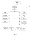
- Figure 1 is a block diagram of a portable electronic device according to an embodiment
- Figure 2 is a front view of the portable electronic device of Figure 1 ;
- Figure 3 is a block diagram including a media player application of the portable electronic device of Figure 1 ;
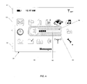
- Figure 4 is a view of a display screen of the portable electronic device of Figure 1 showing an overlay indicating a speaker volume;
- Figures 5A-5C are views of the overlay of Figure 4 according to alternative embodiments.
- Figure 6 is a view of a display screen of the portable electronic device of Figure 1 showing an overlay indicating a headset volume;
- Figures 7A-7C are views of the overlay of Figure 6 according to alternative embodiments.
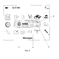
- Figure 8 is a view of a display screen of the portable electronic device of Figure 1 showing an overlay indicating a BluetoothTM device volume;
- Figures 9A-9D are views of the overlay of Figure 6 according to alternative embodiments.
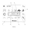
- Figure 10 is a view of a display screen of the portable electronic device of Figure 1 showing an overlay including a volume control indicator;
- Figure 11 is a view of a display screen of the portable electronic device of Figure 1 showing an overlay indicating a BluetoothTM device volume and power level;
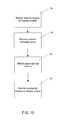
- Figure 12 is a flowchart depicting a method of operating the portable electronic device of Figure 1 according to an embodiment
- Figure 13 is a flowchart depicting a method of operating the portable electronic device of Figure 1 according to another embodiment.
- the portable electronic device 10 includes data communication capabilities and may communicate with other electronic devices directly or through a wireless network.
- the portable electronic device 10 is based on the computing environment and functionality of a handheld computer, such as a wireless personal digital assistant (PDA), for example. It will be understood, however, that the portable electronic device 10 is not limited to a wireless personal digital assistant.
- PDA wireless personal digital assistant
- Other portable electronic devices are possible, such as cellular telephones, smart telephones, electronic messaging devices and laptop computers.
- the portable electronic device 10 includes a number of components including processor 14, which controls the overall operation of the device 10.
- a communication subsystem 40 controls data and voice communication functions, such as email, PIN (Personal Identification Number) message functions, SMS (Short Message Service) message functions and cellular telephone functions, for example.
- the communication subsystem 40 is in communication with a wireless network 12, which may be a data-centric wireless network, a voice-centric wireless network or a dual-mode wireless network.
- the communication subsystem 40 is a dual-mode wireless network that supports both voice and data communications.
- the communication subsystem 40 is configured in accordance with the Global System for Mobile Communication (GSM) and General Packet Radio Services (GPRS) standards.
- the communication subsystem 40 may alternatively be configured in accordance with Enhanced Data GSM Environment (EDGE) or Universal Mobile Telecommunications Service (UMTS) standards.
- Other wireless networks may also be associated with the portable electronic device 10, including Code Division Multiple Access (CDMA) or CDMA2000 networks.
- CDMA Code Division Multiple Access
- CDMA2000 Code Division Multiple Access
- Some other examples of data-centric networks include WiFi 802.11, MobitexTM and DataTACTM network communication systems.
- Examples of other voice-centric data networks include Personal Communication Systems (PCS) networks like GSM and Time Division Multiple Access (TDMA) systems.
- PCS Personal Communication Systems
- TDMA Time Division Multiple Access
- the wireless network 12 includes base stations (not shown) that provide a wireless link to the portable electronic device 10.
- Each base station defines a coverage area, or cell, within which communications between the base station and the portable electronic device 10 can be effected. It will be appreciated that the portable electronic device 10 is movable within the cell and can be moved to coverage areas defined by other cells. Data is delivered to the portable electronic device 10 via wireless transmission from the base station. Similarly, data is sent from the portable electronic device 10 via wireless transmission to the base station.
- the communication subsystem 40 further includes a short range communications function, which enables the device 10 to communicate directly with other devices and computer systems without the use of the wireless network 12 through infrared or BluetoothTM technology, for example.
- SIM Subscriber Identity Module
- Removable User Identity Module card 24 is used to identify the user of the mobile device, store personal device settings and enable access to network services, such as email and voice mail, for example, and is not bound to a particular portable electronic device 10.
- the processor 14 is also connected to a Random Access Memory (RAM) 16 and a flash memory 18.
- RAM Random Access Memory
- An operating system and device software are typically stored in flash memory 18 and are executable by the processor 14.
- Some device software components may alternatively be stored in RAM 16.
- the portable electronic device 10 includes computer executable programmed instructions for directing the portable electronic device 10 to implement various applications. Some examples of applications that may be stored on and executed by the device 10 include: electronic messaging, games, calendar, address book and music player applications. Software applications that control basic device operation, such as voice and data communication, are typically installed during manufacture of the device 10. For devices that do not include a SIM card 24, user identification information may be programmed into the flash memory 18.
- the flash memory 18 may alternatively be a persistent storage, a Read-Only Memory (ROM) or other non-volatile storage.
- the processor 14 receives input from various input devices including a keypad 38 and other input devices 36.
- the keypad 38 may be a complete alphanumeric keypad or telephone-type keypad.
- the other input devices 36 may replace or complement the keypad 38 to facilitate input and may include devices such as: single or multi-function buttons, a touch screen, a mouse, a trackball, a capacitive touch sensor or a roller wheel with dynamic button pressing capability.
- the portable electronic device 10 of Figure 2 is shown by way of example and it will be appreciated by a person skilled in the art that many different device types, shapes and input device configurations are possible.
- the processor 14 outputs to various output devices including an LCD display screen 20.
- a microphone 32 and speaker 22 are connected to the processor 14 for cellular telephone functions.
- a data port 34 is connected to the processor 14 for enabling data communication between the portable electronic device 10 and another computing device.
- the data port 34 may include data lines for data transfer and a supply line for charging a battery 30 of the portable device 10.
- Battery interface 28 is provided for receiving one or more rechargeable batteries 30.
- the portable electronic device 10 is operable in a data communication mode and a voice communication mode.
- a received data signal representing information such as a text message, an email message, a media file to be transferred, or web page download is processed by the communication subsystem 40 and input to the processor 14.
- the processor 14 further processes the signal and renders images for display on the display screen 20. Alternatively, the processed signals may be output to another computing device through the data port 34.
- the user of the portable electronic device 10 composes information for transmission, such as email messages, for example, using the keypad 38 and other input devices 36 in conjunction with the display screen 20.
- the composed information is transmitted through the communication subsystem 40 over the wireless network 12 or via short range communications.
- Operation of the portable electronic device 10 in the voice communication mode is similar to the data communication mode, however, the received signals are output to the speaker 22, or an auxiliary device such as a headset or headphones, and signals for transmission are generated by the microphone 32.
- the portable electronic device 10 may also include other voice subsystems, such as a voice message recording subsystem, for example.
- Audio jack 35 is provided for receiving an audio accessory such as headphones, a headset, amplified speakers or amplified headphones, for example. Audio jack 35 may also receive other accessories such as a multi-media accessory including play, pause, stop and rewind buttons or a TV-out accessory that allows for connection of the portable electronic device to a TV, for example.
- a media player application 42 which is stored on the portable electronic device 10 and executable by the processor 12, is in communication with audio sinks 55 of the portable electronic device 10 in order to output audio thereto.
- the audio sinks 55 include an internal speaker 44, a BluetoothTM device 46 and a wired headset 48.
- an audio file which contains audio data, often encoded, in some machine-usable format, may also be stored in one or more memory elements on the portable electronic device 10.
- an audio file may be stored remotely from portable electronic device 10, and may be received by the portable electronic device 10 by, for example, the wireless network 12.
- audio files are processed by media player application 42 to produce audio output to one or more audio sinks 55.
- media player application 42 can process audio files exclusively, and in other embodiments, media player application 42 can process other forms of media, such as video with an audio component.
- the media player application 42 may be any media player application that manages a set of volume levels for audio sinks and is capable of at least sending audio output.
- the media player application 42 communicates with an audio router application 45, which is stored on the portable electronic device 10 and executable by the processor 12.
- the audio router application manages audio sink activation on the portable electronic device 10 and sends notifications to the media player application 42 when audio routing changes.
- the media player application 42 communicates with the audio router application 45 in order to query current audio routing and current volume level from the audio sinks 55.
- the audio router application 45 automatically switches a current audio routing from a current audio sink to a new audio sink upon connection of the new audio sink to the device 10.
- the audio routing application 45 generates a list of audio sinks that are currently connected to the device 10 in a menu that is provided by the media player application 42. The audio router application 45 switches a current audio routing to a new audio routing based on user selection of a new audio sink.
- the media player application 42 may provide audio output to any internal or auxiliary audio sinks that communicate with the portable electronic device 10 via a wired or wireless connection.
- Examples of other audio sinks include: auxiliary speakers, additional internal speakers, headphones and car kits that allow hands-free operation of the portable electronic device while driving.
- the media player application 42 is also in communication with a volume adjustment device 50 of the portable electronic device 10 in order to receive volume change notifications.
- the volume adjustment device 50 includes a volume down button 52 and a volume up button 54 that are mounted in a housing 15 of the portable electronic device, as shown in Figure 2 .
- the buttons 52, 54 may form part of the keypad 38 or may be separate, as shown.
- Electrical switches (not shown) are provided in communication with the volume down/up buttons 52, 54. Actuation of the volume down/up buttons 52, 54 generates signals that are sent via the processor 12 and received as volume change notifications by the media player application 42. Once received by the media player application 42, the volume change is applied to the audio sink by the audio router application 45 via a wired or wireless connection depending which audio sink is currently active.
- the volume adjustment device 50 is incorporated into one of the other input devices 36 provided on the portable electronic device 10.
- the volume adjustment device 50 may be a separate input device.
- the volume adjustment device 50 is located on the audio sink.
- the audio sink in this embodiment is capable of sending volume change requests to the portable electronic device 10 in response to actuation of the local volume adjustment device 50.
- the volume change requests may be sent wirelessly or through a wired connection to the portable electronic device 10.
- data that has been rendered for display by the processor 12 is shown on the display screen 20 of the portable electronic device 10.
- the data includes device status information 51 and icons 53, which represent software applications, folders and device settings, for example.
- a background image (not shown) may also be provided.
- the background image may be a default image that is provided by the manufacturer of the portable electronic device 10 or a personalized image that has been saved to the device 10 by the user.
- Other forms of data that may be on the display screen 20 of the portable electronic device 10 include video data, including video data that is synchronized with audio output.
- the status information includes time, a new message indicator and battery and signal strength indicators. Other status information related to the device 10 may also be provided.
- the icons when selected by the user, launch software applications that are stored on the device 10, navigate through information that is stored on the device or allow for modification of device settings.
- the media player application 42 communicates with the display screen 20 of the portable electronic device 10 to output an overlay 56, which provides the user with an indication of the audio sink that is currently active and the volume level that is associated with the audio sink.
- the overlay 56 is rendered for display by the processor 12 in response to a volume adjustment event. It will be appreciated by a person skilled in the art that when no volume adjustment event has occurred, the overlay 56 is not rendered for display.
- Volume adjustment events include: user actuation of the volume adjustment device 50, addition of an audio sink and removal of an audio sink.
- the overlay 56 may disappear, that is, the overlay 56 may be no longer rendered or superimposed, and the data that had been under the overlay may be re-rendered.
- the overlay 56 may disappear after a period of time, such as a few seconds. In other embodiments, the overlay 56 may disappear after a user supplies a command to the portable electronic device 10 to clear the overlay 56, or the overlay may disappear in response to another event such as activation of an alarm or receipt of an email message, for example, or any combination thereof.
- the overlay 56 may persist without disappearing for any length of time, and in some embodiments, the user may input a preference into the portable electronic device 10 as to how long the overlay 56 should persist before disappearing.
- the overlay 56 is superimposed over the data on the display screen 20.
- the overlay 56 includes: an audio sink indicator 58, a volume indicator 60 and a background field 62, which functions to visually separate the audio sink indicator 58 and the volume indicator 60 from the data on the display screen 20.
- the depiction of overlay 56 is for illustrative purposes, and the concepts described herein are not limited to that particular depiction.
- the superimposed overlay 56 is effectively opaque.
- the concepts described herein include superimposition of a partially transparent overlay, such that icons, a background image or other the data on the display screen 20 could be perceived as being "seen through" the overlay.
- the overlay 56 appears in Figure 4 as being rendered near the center of the display screen 20, the concepts described herein include rendering of the overlay anywhere on the display screen 20.
- the overlay may be rendered in a dedicated area of the display screen 20, that is, in a location in which no icons or other data routinely appear.
- the overlay 56 is depicted with a background field 62 in the shape of a rounded rectangle, but the concepts described herein are not restricted to any particular shape or shapes.
- the audio sink indicator 58 is a speaker symbol, which indicates to the device user that the audio sink that is currently active is the internal speaker 44
- the volume indicator 60 is a volume level indicator having a bar 64 that increases in length when the volume increases.
- the concepts described herein are not limited to use of a bar to indicate volume level.
- the volume indicator 60 may include a volume level indicator in the form of (for example) a color, or a number or a needle on a scale, or any combination thereof.
- Figures 5A, 5B and 5C shown alternative embodiments of the overlay 56.
- the text "SPEAKER" is provided. It will be appreciated that any other text that identifies the audio sink to the user may alternatively be used.
- Figure 5B shows a combination of symbol and text.
- Figure 5C shows the overlay 56 including only the audio sink indicator 58 and the volume indicator 60. In this embodiment, the background field 62 has been removed.
- the audio sink indicator 58 is a headset symbol, which indicates to the device user that the audio sink that is currently active is the headset 48.
- Figures 7A, 7B and 7C shown alternative embodiments of the overlay 56.
- the audio sink indicator 58 is text.
- the audio sink indicator 58 is a combination of symbol and text.
- the overlay 56 includes only the audio sink indicator 58 and the volume indicator 60.
- the audio sink indicator 58 is a BluetoothTM symbol, which indicates to the device user that the audio sink that is currently active is a BluetoothTM device 46.
- Figures 9A, 9B and 9C show alternative embodiments of the overlay 56.
- the audio sink indicator 58 is text.
- the audio sink indicator 58 is a combination of symbol and text.
- the overlay 56 includes only the audio sink indicator 58 and the volume indicator 60.
- the BluetoothTM device symbol may be customized to visually identify which type of BluetoothTM device is connected, as shown in Figure 9D , for example. Further, if the audio sink communicates with the portable electronic device 10 via a different type of short range communication, such as infrared, WiFi or wireless USB, the audio sink indicator 58 will be selected to indicate this accordingly.
- the volume indicator is a volume control indicator instead of a volume level indicator.
- a minus (-) symbol 66 and a plus (+) symbol 68 are visually modified to indicate a decrease in volume and an increase in volume, respectively, in response to actuation of the volume adjustment device 50 by the user.
- the visual modification is a brief flash to indicate to the user that the device 10 is handling the volume adjustment device 50.
- a volume control indicator may be useful in cases in which it is difficult to assess the volume level of an audio sink, but it is less difficult to assess whether the user is increasing or decreasing the level of the volume.
- the volume indicator may include both a volume control indicator and of a volume level indicator.
- a minus (-) symbol 66 and a plus (+) symbol 68 are shown in the embodiment of Figure 10 , it will be appreciated by a person skilled in the art that other symbols may be provided on the volume control indicator, such as a small circle and a larger circle, for example.
- a power level indicator 70 is provided along with the audio sink indicator 58 and the volume indicator 60.
- the overlay 56 further includes the background field 62, however, this is optional.
- This embodiment is used when the audio sink is a BluetoothTM device or other short range communication device to indicate the battery power level, or state of charge, of the audio sink.
- the audio sink indicator 58 is rendered with a color to indicate the power level of the audio sink. For example, the audio sink indicator 58 may appear green when the battery of the audio sink is fully charged, the audio sink indicator 58 may appear yellow when the battery of the audio sink is partially charged and the audio sink indicator 58 may appear red when the battery of the audio sink has a low charge.
- the portable electronic device 10 includes the volume adjustment device 50, which is in communication with the media player application 42 that is stored on the device 10 and in communication with the processor 12, and the processor 12.
- the processor 12 renders data for display on the display screen 20 of the device 10 and renders an overlay 56 for display on the display screen 20.
- the overlay 56 includes the volume indicator 60 and the audio sink indicator 58 and is superimposed over the data.
- An active audio sink and current volume level of the active audio sink are obtained from the media player application.
- Step 72 data is rendered for display on the display screen 20 of the portable electronic device 10.
- the overlay 56 which includes the audio sink indicator 58 and the volume indicator 60, is rendered for display on the display screen 20.
- Step 72 is performed by the processor 12 in a first computer process and Step 74 is performed by the processor 12 in a second computer process. That is, the first computer process and the second computer process may generally be performed independently, though a user may perceive them as being performed together and simultaneously. Alternatively, output from the first computer process may be used as input for the second computer process so that re-rendering of the data surrounding the overlay 56 is not performed and thus computer processing time is reduced.
- the processor 12 may optionally cause the overlay 56 to disappear after being rendered in response to an event or a command or a passage of time.
- step 76 data is rendered for display on the display screen 20 of the portable electronic device 10.
- step 78 a volume adjustment event is received by the processor 12 of the portable electronic device 10.
- volume adjustment event When the volume adjustment event is user actuation of the volume adjustment device 50, electrical switches generate signals that are sent to the media player application 42.
- the media player application 42 then responds by increasing or decreasing the volume of the currently playing media (step 80).
- an audio sink connect message is generated by the circuitry of the audio jack 35 of the portable electronic device 10 or by radio signals received by an antenna of the communications subsystem 40.
- the audio router application 45 responds to the connect message by applying current audio routing rules in order to determine if currently playing media should be routed to the new audio sink.
- the audio routing rules include logic statements that consider the audio source (media player, alert, ringtone, voice note, email attachment, for example) and the audio sink that is best suited to handle the audio source. Default routing rules may be overridden by user selection of the audio sink. If the audio router application 45 adopts the newly connected audio sink as the current audio sink, an audio sink change notification is sent by the audio router application 45.
- the notification is received by the media player application 42, which records the new audio routing.
- the newly added audio sink is selected as the current audio sink
- the last known volume, which is stored in flash memory 18 of the portable electronic device 10 of the newly added audio route is applied to the currently selected media being output from the media player application 42 (step 80).
- an audio sink disconnect message is generated and the audio routing application 45 applies the audio routing rules to re-direct the currently playing media to a different audio sink.
- the last known volume for the new audio route is then applied to the currently selected media being output from the media player application 42 (step 80). It will be appreciated by a person skilled in the art that the overlay 56 is only displayed when the current audio sink is disconnected from the device 10. Removal of an audio sink that is not currently in use, for example removing a wired headset when the audio is being played by the internal speaker of the device 10, will not cause the overlay 56 to be displayed.
- the overlay 56 which includes the audio sink indicator 58 and the volume indicator 60, is rendered for display on the display screen 20 in response to the volume adjustment event.
- the embodiments described herein, and variations thereof, may provide one of more advantages. They may assist users who switch between audio sinks and find that they have to adjust the volume and allow users to receive visual feedback as to which audio sink is activated as well as information about the volume of that audio sink.
- the concepts described above are adaptable to a variety of portable electronic devices and a variety of audio sinks. Further, various embodiments may be applied to instances in which the audio is part of a multimedia presentation, such as a video displayed with the audio.
- the advantages of the embodiments described herein are particularly apparent when the volume of a previously selected audio sink was very high or very low.
- the volume output from the external speaker may be so low that the audio is imperceptible to the user.
- the user is not left wondering i) if the new audio sink has been correctly selected or ii) if the external speaker is working properly.
- the volume level is very high on an external speaker, for example, and the user switches to a headset, for example, the user does not experience the discomfort associated with high volume being perceived at very close range.
Landscapes
- Engineering & Computer Science (AREA)
- Theoretical Computer Science (AREA)
- Human Computer Interaction (AREA)
- Audiology, Speech & Language Pathology (AREA)
- General Health & Medical Sciences (AREA)
- Health & Medical Sciences (AREA)
- Physics & Mathematics (AREA)
- General Engineering & Computer Science (AREA)
- General Physics & Mathematics (AREA)
- Multimedia (AREA)
- Computer Networks & Wireless Communication (AREA)
- Signal Processing (AREA)
- Circuit For Audible Band Transducer (AREA)
Abstract
Description
- The present embodiments relate to visual identification of audio sink volume on a portable electronic device.
- Portable electronic devices are capable of sending audio output to several different audio sinks including internal speakers, wired auxiliary devices such as headsets and speakers, for example, and wireless auxiliary devices that communicate with the portable electronic device over a wireless protocol such as Bluetooth™, for example.
- Controlling the volume of the different audio sinks on the portable electronic device is typically performed by depressing individual volume up/down keys or manipulating a trackball or a thumbwheel to increase or decrease the volume. Volume adjustment is associated with the default audio sink of the portable electronic device, which for most devices is the internal speaker. When another audio sink is enabled by, for example, plugging a headset into the device, the volume adjustment becomes associated with the new audio sink.
- Users who frequently switch between audio sinks generally have to adjust the volume each time a new audio sink is enabled. A current volume level may not be desired and may even cause the user some discomfort when a new sink is activated. For example, a user listening to music from a loudspeaker at a very high volume must rush to adjust the volume when headphones are plugged in to avoid being blasted with music at an undesired high level.
- There is provided herein a method including: rendering data for display on a display screen of a portable electronic device and rendering an overlay for display on the display screen, the overlay being superimposed over the data and comprising a volume indicator and an audio sink indicator.
- There is provided herein a portable electronic device including: a processor for rendering data for display on a display screen of the portable electronic device and rendering an overlay for display on the display screen, the overlay comprising a volume indicator and an audio sink indicator and being superimposed over the data; and a volume adjustment device in communication with the processor, the volume adjustment device for communicating with a media player application stored in a memory of the portable electronic device; wherein active audio sink and current volume level of the active audio sink is obtained from the media player application.
- The following figures set forth embodiments in which like reference numerals denote like parts. Embodiments are illustrated by way of example and not by way of limitation in the accompanying figures.
-
Figure 1 is a block diagram of a portable electronic device according to an embodiment; -
Figure 2 is a front view of the portable electronic device ofFigure 1 ; -
Figure 3 is a block diagram including a media player application of the portable electronic device ofFigure 1 ; -
Figure 4 is a view of a display screen of the portable electronic device ofFigure 1 showing an overlay indicating a speaker volume; -
Figures 5A-5C are views of the overlay ofFigure 4 according to alternative embodiments; -
Figure 6 is a view of a display screen of the portable electronic device ofFigure 1 showing an overlay indicating a headset volume; -
Figures 7A-7C are views of the overlay ofFigure 6 according to alternative embodiments; -
Figure 8 is a view of a display screen of the portable electronic device ofFigure 1 showing an overlay indicating a Bluetooth™ device volume; -
Figures 9A-9D are views of the overlay ofFigure 6 according to alternative embodiments; -
Figure 10 is a view of a display screen of the portable electronic device ofFigure 1 showing an overlay including a volume control indicator; -
Figure 11 is a view of a display screen of the portable electronic device ofFigure 1 showing an overlay indicating a Bluetooth™ device volume and power level; -
Figure 12 is a flowchart depicting a method of operating the portable electronic device ofFigure 1 according to an embodiment; and -
Figure 13 is a flowchart depicting a method of operating the portable electronic device ofFigure 1 according to another embodiment. - Referring now to
Figure 1 , components of a portableelectronic device 10 according to an embodiment are generally shown. The portableelectronic device 10 includes data communication capabilities and may communicate with other electronic devices directly or through a wireless network. The portableelectronic device 10 is based on the computing environment and functionality of a handheld computer, such as a wireless personal digital assistant (PDA), for example. It will be understood, however, that the portableelectronic device 10 is not limited to a wireless personal digital assistant. Other portable electronic devices are possible, such as cellular telephones, smart telephones, electronic messaging devices and laptop computers. - The portable
electronic device 10 includes a number ofcomponents including processor 14, which controls the overall operation of thedevice 10. Acommunication subsystem 40 controls data and voice communication functions, such as email, PIN (Personal Identification Number) message functions, SMS (Short Message Service) message functions and cellular telephone functions, for example. Thecommunication subsystem 40 is in communication with awireless network 12, which may be a data-centric wireless network, a voice-centric wireless network or a dual-mode wireless network. - In
Figure 1 , thecommunication subsystem 40 is a dual-mode wireless network that supports both voice and data communications. Thecommunication subsystem 40 is configured in accordance with the Global System for Mobile Communication (GSM) and General Packet Radio Services (GPRS) standards. Thecommunication subsystem 40 may alternatively be configured in accordance with Enhanced Data GSM Environment (EDGE) or Universal Mobile Telecommunications Service (UMTS) standards. Other wireless networks may also be associated with the portableelectronic device 10, including Code Division Multiple Access (CDMA) or CDMA2000 networks. Some other examples of data-centric networks include WiFi 802.11, Mobitex™ and DataTAC™ network communication systems. Examples of other voice-centric data networks include Personal Communication Systems (PCS) networks like GSM and Time Division Multiple Access (TDMA) systems. - The
wireless network 12 includes base stations (not shown) that provide a wireless link to the portableelectronic device 10. Each base station defines a coverage area, or cell, within which communications between the base station and the portableelectronic device 10 can be effected. It will be appreciated that the portableelectronic device 10 is movable within the cell and can be moved to coverage areas defined by other cells. Data is delivered to the portableelectronic device 10 via wireless transmission from the base station. Similarly, data is sent from the portableelectronic device 10 via wireless transmission to the base station. - The
communication subsystem 40 further includes a short range communications function, which enables thedevice 10 to communicate directly with other devices and computer systems without the use of thewireless network 12 through infrared or Bluetooth™ technology, for example. - Prior to the portable
electronic device 10 being able to send and receive communication signals over thewireless network 12, network registration or activation procedures must have been completed. In order to enable network communication, a SIM (Subscriber Identity Module)card 24 is inserted into acard interface 26. The SIM card, or Removable User Identity Module card, is used to identify the user of the mobile device, store personal device settings and enable access to network services, such as email and voice mail, for example, and is not bound to a particular portableelectronic device 10. - The
processor 14 is also connected to a Random Access Memory (RAM) 16 and aflash memory 18. An operating system and device software are typically stored inflash memory 18 and are executable by theprocessor 14. Some device software components may alternatively be stored inRAM 16. The portableelectronic device 10 includes computer executable programmed instructions for directing the portableelectronic device 10 to implement various applications. Some examples of applications that may be stored on and executed by thedevice 10 include: electronic messaging, games, calendar, address book and music player applications. Software applications that control basic device operation, such as voice and data communication, are typically installed during manufacture of thedevice 10. For devices that do not include aSIM card 24, user identification information may be programmed into theflash memory 18. Theflash memory 18 may alternatively be a persistent storage, a Read-Only Memory (ROM) or other non-volatile storage. - Referring also to
Figure 2 , theprocessor 14 receives input from various input devices including akeypad 38 andother input devices 36. Thekeypad 38 may be a complete alphanumeric keypad or telephone-type keypad. Theother input devices 36 may replace or complement thekeypad 38 to facilitate input and may include devices such as: single or multi-function buttons, a touch screen, a mouse, a trackball, a capacitive touch sensor or a roller wheel with dynamic button pressing capability. The portableelectronic device 10 ofFigure 2 is shown by way of example and it will be appreciated by a person skilled in the art that many different device types, shapes and input device configurations are possible. - The
processor 14 outputs to various output devices including anLCD display screen 20. Amicrophone 32 andspeaker 22 are connected to theprocessor 14 for cellular telephone functions. Adata port 34 is connected to theprocessor 14 for enabling data communication between the portableelectronic device 10 and another computing device. Thedata port 34 may include data lines for data transfer and a supply line for charging abattery 30 of theportable device 10.Battery interface 28 is provided for receiving one or morerechargeable batteries 30. - The portable
electronic device 10 is operable in a data communication mode and a voice communication mode. In the data communication mode, a received data signal representing information such as a text message, an email message, a media file to be transferred, or web page download is processed by thecommunication subsystem 40 and input to theprocessor 14. Theprocessor 14 further processes the signal and renders images for display on thedisplay screen 20. Alternatively, the processed signals may be output to another computing device through thedata port 34. In order to transmit information in the data communication mode, the user of the portableelectronic device 10 composes information for transmission, such as email messages, for example, using thekeypad 38 andother input devices 36 in conjunction with thedisplay screen 20. The composed information is transmitted through thecommunication subsystem 40 over thewireless network 12 or via short range communications. Operation of the portableelectronic device 10 in the voice communication mode is similar to the data communication mode, however, the received signals are output to thespeaker 22, or an auxiliary device such as a headset or headphones, and signals for transmission are generated by themicrophone 32. The portableelectronic device 10 may also include other voice subsystems, such as a voice message recording subsystem, for example.Audio jack 35 is provided for receiving an audio accessory such as headphones, a headset, amplified speakers or amplified headphones, for example.Audio jack 35 may also receive other accessories such as a multi-media accessory including play, pause, stop and rewind buttons or a TV-out accessory that allows for connection of the portable electronic device to a TV, for example. - Only a limited number of device subsystems have been described. It will be appreciated by a person skilled in the art that additional subsystems corresponding to additional device features may also be connected to the
processor 14. - Referring to
Figure 3 , amedia player application 42, which is stored on the portableelectronic device 10 and executable by theprocessor 12, is in communication withaudio sinks 55 of the portableelectronic device 10 in order to output audio thereto. As shown in the embodiment ofFigure 3 , the audio sinks 55 include aninternal speaker 44, aBluetooth™ device 46 and awired headset 48. Although not depicted inFigure 3 , an audio file, which contains audio data, often encoded, in some machine-usable format, may also be stored in one or more memory elements on the portableelectronic device 10. Alternatively, an audio file may be stored remotely from portableelectronic device 10, and may be received by the portableelectronic device 10 by, for example, thewireless network 12. Regardless of where the audio files are stored, audio files are processed bymedia player application 42 to produce audio output to one or more audio sinks 55. In some embodiments,media player application 42 can process audio files exclusively, and in other embodiments,media player application 42 can process other forms of media, such as video with an audio component. - It will be appreciated by a person skilled in the art that the
media player application 42 may be any media player application that manages a set of volume levels for audio sinks and is capable of at least sending audio output. - The
media player application 42 communicates with anaudio router application 45, which is stored on the portableelectronic device 10 and executable by theprocessor 12. The audio router application manages audio sink activation on the portableelectronic device 10 and sends notifications to themedia player application 42 when audio routing changes. Themedia player application 42 communicates with theaudio router application 45 in order to query current audio routing and current volume level from the audio sinks 55. - In one embodiment, the
audio router application 45 automatically switches a current audio routing from a current audio sink to a new audio sink upon connection of the new audio sink to thedevice 10. In another embodiment, theaudio routing application 45 generates a list of audio sinks that are currently connected to thedevice 10 in a menu that is provided by themedia player application 42. Theaudio router application 45 switches a current audio routing to a new audio routing based on user selection of a new audio sink. - It will be appreciated by a person skilled in the art that the
media player application 42 may provide audio output to any internal or auxiliary audio sinks that communicate with the portableelectronic device 10 via a wired or wireless connection. Examples of other audio sinks include: auxiliary speakers, additional internal speakers, headphones and car kits that allow hands-free operation of the portable electronic device while driving. - The
media player application 42 is also in communication with avolume adjustment device 50 of the portableelectronic device 10 in order to receive volume change notifications. In one embodiment, thevolume adjustment device 50 includes a volume downbutton 52 and a volume upbutton 54 that are mounted in ahousing 15 of the portable electronic device, as shown inFigure 2 . Thebuttons keypad 38 or may be separate, as shown. Electrical switches (not shown) are provided in communication with the volume down/upbuttons buttons processor 12 and received as volume change notifications by themedia player application 42. Once received by themedia player application 42, the volume change is applied to the audio sink by theaudio router application 45 via a wired or wireless connection depending which audio sink is currently active. - In another embodiment, the
volume adjustment device 50 is incorporated into one of theother input devices 36 provided on the portableelectronic device 10. Alternatively, thevolume adjustment device 50 may be a separate input device. In a further embodiment, thevolume adjustment device 50 is located on the audio sink. The audio sink in this embodiment is capable of sending volume change requests to the portableelectronic device 10 in response to actuation of the localvolume adjustment device 50. The volume change requests may be sent wirelessly or through a wired connection to the portableelectronic device 10. - Referring to
Figure 4 , data that has been rendered for display by theprocessor 12 is shown on thedisplay screen 20 of the portableelectronic device 10. The data includesdevice status information 51 andicons 53, which represent software applications, folders and device settings, for example. A background image (not shown) may also be provided. The background image may be a default image that is provided by the manufacturer of the portableelectronic device 10 or a personalized image that has been saved to thedevice 10 by the user. Other forms of data that may be on thedisplay screen 20 of the portableelectronic device 10 include video data, including video data that is synchronized with audio output. - The status information includes time, a new message indicator and battery and signal strength indicators. Other status information related to the
device 10 may also be provided. The icons, when selected by the user, launch software applications that are stored on thedevice 10, navigate through information that is stored on the device or allow for modification of device settings. - Referring back to
Figure 3 , themedia player application 42 communicates with thedisplay screen 20 of the portableelectronic device 10 to output anoverlay 56, which provides the user with an indication of the audio sink that is currently active and the volume level that is associated with the audio sink. Theoverlay 56 is rendered for display by theprocessor 12 in response to a volume adjustment event. It will be appreciated by a person skilled in the art that when no volume adjustment event has occurred, theoverlay 56 is not rendered for display. Volume adjustment events include: user actuation of thevolume adjustment device 50, addition of an audio sink and removal of an audio sink. Theoverlay 56 may disappear, that is, theoverlay 56 may be no longer rendered or superimposed, and the data that had been under the overlay may be re-rendered. Even if the data that had been under theoverlay 56 comprised a blank screen, re-rendering might be advantageous to remove any vestige of theoverlay 56. In some embodiments, theoverlay 56 may disappear after a period of time, such as a few seconds. In other embodiments, theoverlay 56 may disappear after a user supplies a command to the portableelectronic device 10 to clear theoverlay 56, or the overlay may disappear in response to another event such as activation of an alarm or receipt of an email message, for example, or any combination thereof. Theoverlay 56 may persist without disappearing for any length of time, and in some embodiments, the user may input a preference into the portableelectronic device 10 as to how long theoverlay 56 should persist before disappearing. - As shown in
Figure 4 , theoverlay 56 is superimposed over the data on thedisplay screen 20. Theoverlay 56 includes: anaudio sink indicator 58, avolume indicator 60 and abackground field 62, which functions to visually separate theaudio sink indicator 58 and thevolume indicator 60 from the data on thedisplay screen 20. The depiction ofoverlay 56 is for illustrative purposes, and the concepts described herein are not limited to that particular depiction. InFigure 4 , for example, the superimposedoverlay 56 is effectively opaque. The concepts described herein include superimposition of a partially transparent overlay, such that icons, a background image or other the data on thedisplay screen 20 could be perceived as being "seen through" the overlay. In addition, although theoverlay 56 appears inFigure 4 as being rendered near the center of thedisplay screen 20, the concepts described herein include rendering of the overlay anywhere on thedisplay screen 20. The overlay may be rendered in a dedicated area of thedisplay screen 20, that is, in a location in which no icons or other data routinely appear. Further, theoverlay 56 is depicted with abackground field 62 in the shape of a rounded rectangle, but the concepts described herein are not restricted to any particular shape or shapes. - In the example shown in
Figure 4 , theaudio sink indicator 58 is a speaker symbol, which indicates to the device user that the audio sink that is currently active is theinternal speaker 44, and thevolume indicator 60 is a volume level indicator having a bar 64 that increases in length when the volume increases. The concepts described herein are not limited to use of a bar to indicate volume level. Thevolume indicator 60 may include a volume level indicator in the form of (for example) a color, or a number or a needle on a scale, or any combination thereof. -
Figures 5A, 5B and 5C shown alternative embodiments of theoverlay 56. InFigure 5A , instead of a symbol, the text "SPEAKER" is provided. It will be appreciated that any other text that identifies the audio sink to the user may alternatively be used.Figure 5B shows a combination of symbol and text.Figure 5C shows theoverlay 56 including only theaudio sink indicator 58 and thevolume indicator 60. In this embodiment, thebackground field 62 has been removed. - Referring to
Figure 6 , theaudio sink indicator 58 is a headset symbol, which indicates to the device user that the audio sink that is currently active is theheadset 48.Figures 7A, 7B and 7C shown alternative embodiments of theoverlay 56. InFigure 7A , theaudio sink indicator 58 is text. InFigure 7B , theaudio sink indicator 58 is a combination of symbol and text. InFigure 5C , theoverlay 56 includes only theaudio sink indicator 58 and thevolume indicator 60. - Referring to
Figure 8 , theaudio sink indicator 58 is a Bluetooth™ symbol, which indicates to the device user that the audio sink that is currently active is aBluetooth™ device 46.Figures 9A, 9B and 9C show alternative embodiments of theoverlay 56. InFigure 9A , theaudio sink indicator 58 is text. InFigure 9B , theaudio sink indicator 58 is a combination of symbol and text. InFigure 9C , theoverlay 56 includes only theaudio sink indicator 58 and thevolume indicator 60. The Bluetooth™ device symbol may be customized to visually identify which type of Bluetooth™ device is connected, as shown inFigure 9D , for example. Further, if the audio sink communicates with the portableelectronic device 10 via a different type of short range communication, such as infrared, WiFi or wireless USB, theaudio sink indicator 58 will be selected to indicate this accordingly. - Referring to
Figure 10 , another embodiment of anoverlay 56 is shown. In this embodiment, the volume indicator is a volume control indicator instead of a volume level indicator. A minus (-)symbol 66 and a plus (+)symbol 68 are visually modified to indicate a decrease in volume and an increase in volume, respectively, in response to actuation of thevolume adjustment device 50 by the user. In one embodiment the visual modification is a brief flash to indicate to the user that thedevice 10 is handling thevolume adjustment device 50. A volume control indicator may be useful in cases in which it is difficult to assess the volume level of an audio sink, but it is less difficult to assess whether the user is increasing or decreasing the level of the volume. In some embodiments, the volume indicator may include both a volume control indicator and of a volume level indicator. Although a minus (-)symbol 66 and a plus (+)symbol 68 are shown in the embodiment ofFigure 10 , it will be appreciated by a person skilled in the art that other symbols may be provided on the volume control indicator, such as a small circle and a larger circle, for example. - Referring to
Figure 11 , another embodiment of theoverlay 56 is shown. In this embodiment, apower level indicator 70 is provided along with theaudio sink indicator 58 and thevolume indicator 60. As shown, theoverlay 56 further includes thebackground field 62, however, this is optional. This embodiment is used when the audio sink is a Bluetooth™ device or other short range communication device to indicate the battery power level, or state of charge, of the audio sink. In one embodiment, theaudio sink indicator 58 is rendered with a color to indicate the power level of the audio sink. For example, theaudio sink indicator 58 may appear green when the battery of the audio sink is fully charged, theaudio sink indicator 58 may appear yellow when the battery of the audio sink is partially charged and theaudio sink indicator 58 may appear red when the battery of the audio sink has a low charge. - In one embodiment the portable
electronic device 10 includes thevolume adjustment device 50, which is in communication with themedia player application 42 that is stored on thedevice 10 and in communication with theprocessor 12, and theprocessor 12. Theprocessor 12 renders data for display on thedisplay screen 20 of thedevice 10 and renders anoverlay 56 for display on thedisplay screen 20. Theoverlay 56 includes thevolume indicator 60 and theaudio sink indicator 58 and is superimposed over the data. An active audio sink and current volume level of the active audio sink are obtained from the media player application. - Referring to
Figure 12 , a method of operating the portableelectronic device 10 is generally shown. Atstep 72, data is rendered for display on thedisplay screen 20 of the portableelectronic device 10. Atstep 74, theoverlay 56, which includes theaudio sink indicator 58 and thevolume indicator 60, is rendered for display on thedisplay screen 20.Step 72 is performed by theprocessor 12 in a first computer process and Step 74 is performed by theprocessor 12 in a second computer process. That is, the first computer process and the second computer process may generally be performed independently, though a user may perceive them as being performed together and simultaneously. Alternatively, output from the first computer process may be used as input for the second computer process so that re-rendering of the data surrounding theoverlay 56 is not performed and thus computer processing time is reduced. As noted above, theprocessor 12 may optionally cause theoverlay 56 to disappear after being rendered in response to an event or a command or a passage of time. - Referring to
Figure 13 , another method of operating the portableelectronic device 10 is generally shown. Atstep 76, data is rendered for display on thedisplay screen 20 of the portableelectronic device 10. Atstep 78, a volume adjustment event is received by theprocessor 12 of the portableelectronic device 10. - When the volume adjustment event is user actuation of the
volume adjustment device 50, electrical switches generate signals that are sent to themedia player application 42. Themedia player application 42 then responds by increasing or decreasing the volume of the currently playing media (step 80). - When the volume adjustment event is addition of an audio sink, an audio sink connect message is generated by the circuitry of the
audio jack 35 of the portableelectronic device 10 or by radio signals received by an antenna of thecommunications subsystem 40. Theaudio router application 45 responds to the connect message by applying current audio routing rules in order to determine if currently playing media should be routed to the new audio sink. The audio routing rules include logic statements that consider the audio source (media player, alert, ringtone, voice note, email attachment, for example) and the audio sink that is best suited to handle the audio source. Default routing rules may be overridden by user selection of the audio sink. If theaudio router application 45 adopts the newly connected audio sink as the current audio sink, an audio sink change notification is sent by theaudio router application 45. The notification is received by themedia player application 42, which records the new audio routing. When the newly added audio sink is selected as the current audio sink, the last known volume, which is stored inflash memory 18 of the portableelectronic device 10, of the newly added audio route is applied to the currently selected media being output from the media player application 42 (step 80). - When the volume adjustment event is the removal of an audio sink, an audio sink disconnect message is generated and the
audio routing application 45 applies the audio routing rules to re-direct the currently playing media to a different audio sink. The last known volume for the new audio route is then applied to the currently selected media being output from the media player application 42 (step 80). It will be appreciated by a person skilled in the art that theoverlay 56 is only displayed when the current audio sink is disconnected from thedevice 10. Removal of an audio sink that is not currently in use, for example removing a wired headset when the audio is being played by the internal speaker of thedevice 10, will not cause theoverlay 56 to be displayed. - At
step 82, theoverlay 56, which includes theaudio sink indicator 58 and thevolume indicator 60, is rendered for display on thedisplay screen 20 in response to the volume adjustment event. - The embodiments described herein, and variations thereof, may provide one of more advantages. They may assist users who switch between audio sinks and find that they have to adjust the volume and allow users to receive visual feedback as to which audio sink is activated as well as information about the volume of that audio sink. In addition, the concepts described above are adaptable to a variety of portable electronic devices and a variety of audio sinks. Further, various embodiments may be applied to instances in which the audio is part of a multimedia presentation, such as a video displayed with the audio.
- The advantages of the embodiments described herein are particularly apparent when the volume of a previously selected audio sink was very high or very low. In the case where the volume level is very low on a headset, for example, and the user switches to an external speaker, for example, the volume output from the external speaker may be so low that the audio is imperceptible to the user. By visually indicating the current audio sink to the user and the outputting the previously stored volume, the user is not left wondering i) if the new audio sink has been correctly selected or ii) if the external speaker is working properly. Conversely, if the volume level is very high on an external speaker, for example, and the user switches to a headset, for example, the user does not experience the discomfort associated with high volume being perceived at very close range.
- Specific embodiments have been shown and described herein. However, modifications and variations may occur to those skilled in the art. All such modifications and variations are believed to be within the scope and sphere of the present embodiments.
Claims (18)
- A method comprising:rendering data for display on a display screen (20) of a portable electronic device (10); andrendering an overlay (56) for display on the display screen (20), the overlay (56) being superimposed over the data and comprising a volume indicator (60) and an audio sink indicator (58).
- A method as claimed in claim 1, wherein the overlay (56) is rendered in response to a volume adjustment event.
- A method as claimed in claim 2, wherein the volume adjustment event is one of:addition of an audio sink (55) and removal of an audio sink (55).
- A method as claimed in claim 2, wherein the volume adjustment event is actuation of a button (52,54) of the portable electronic device (10).
- A method as claimed in any of claims 1 to 4, wherein the volume indicator (60) is a volume level indicator.
- A method as claimed in any of claims 1 to 5, wherein the volume indicator (60) is a volume control indicator.
- A method as claimed in any of claims 1 to 6, wherein the overlay comprises a power level indicator (70) corresponding to a wireless audio sink.
- A method as claimed in claim 7, wherein the wireless audio sink is a Bluetooth™ device.
- A method as claimed in any of claims 1 to 8, wherein the audio sink indicator (58) is a symbol.
- A method as claimed in any of claims 1 to 9, wherein the audio sink indicator (58) is text.
- A method as claimed in any of claims 1 to 10, wherein the audio sink (58) indicator is a combination of symbol and text.
- A method as claimed in any of claims 1 to 11, wherein the ovenay (56) comprises a background field (62).
- A method as claimed in claim 2, wherein a volume of media being output from an audio sink is adjusted in response to the volume adjustment event.
- A method as claimed in claim 13, wherein the media is one of: an audio file stored on the portable electronic device (10), an audio file received by the portable electronic device (10).
- A method as claimed in any of claims 1 to 14, wherein rendering data for display on a display screen (20) of the portable electronic device (10) is performed in a first computer process and rendering the overlay (56) for display on the display screen (20) is performed in a second computer process.
- A method as claimed in any of claims 1 to 15, comprising: after rendering the overlay (56), re-rendering the data to cause the overlay (56) to disappear.
- A computer-readable medium comprising instructions executable on a processor (14) of the portable electronic device (10) for implementing the method of claim 1.
- A portable electronic device (10) comprising:a processor (14) for rendering data for display on a display screen (20) of the portable electronic device (10) and rendering an overlay (56) for display on the display screen (20), the overlay (56) comprising a volume indicator (60) and an audio sink indicator (58) and being superimposed over the data; anda volume adjustment device (50) in communication with the processor (14), the volume adjustment device (50) for communicating with a media player application (42) stored in a memory (18) of the portable electronic device (10);wherein active audio sink and current volume level of the active audio sink is obtained from the media player application (42).
Applications Claiming Priority (1)
| Application Number | Priority Date | Filing Date | Title |
|---|---|---|---|
| US24993809P | 2009-10-08 | 2009-10-08 |
Publications (1)
| Publication Number | Publication Date |
|---|---|
| EP2309709A1 true EP2309709A1 (en) | 2011-04-13 |
Family
ID=42167420
Family Applications (1)
| Application Number | Title | Priority Date | Filing Date |
|---|---|---|---|
| EP10152872A Withdrawn EP2309709A1 (en) | 2009-10-08 | 2010-02-08 | Method for indicating a volume of an audio sink of a portable electronic device |
Country Status (4)
| Country | Link |
|---|---|
| US (1) | US20110087964A1 (en) |
| EP (1) | EP2309709A1 (en) |
| CN (1) | CN102033800A (en) |
| CA (1) | CA2692058A1 (en) |
Families Citing this family (35)
| Publication number | Priority date | Publication date | Assignee | Title |
|---|---|---|---|---|
| USD523442S1 (en) * | 2004-05-27 | 2006-06-20 | Sony Computer Entertainment Inc. | Computer generated image for a display panel or screen |
| USD668263S1 (en) * | 2010-10-08 | 2012-10-02 | Apple Inc. | Display screen or portion thereof with icon |
| US9043715B2 (en) * | 2011-06-02 | 2015-05-26 | International Business Machines Corporation | Alert event notification |
| USD670736S1 (en) * | 2011-09-09 | 2012-11-13 | Microsoft Corporation | Display screen with icon |
| USD709086S1 (en) | 2012-02-07 | 2014-07-15 | Apple Inc. | Display screen or portion thereof with animated graphical user interface |
| AU345903S (en) * | 2012-03-05 | 2012-12-05 | Apple Inc | Display screen for an electronic device |
| US8971556B2 (en) | 2012-06-10 | 2015-03-03 | Apple Inc. | Remotely controlling a hearing device |
| US9953179B2 (en) * | 2013-05-29 | 2018-04-24 | Sonos, Inc. | Private queue indicator |
| US20150128095A1 (en) * | 2013-11-07 | 2015-05-07 | Tencent Technology (Shenzhen) Company Limited | Method, device and computer system for performing operations on objects in an object list |
| USD786266S1 (en) | 2014-03-07 | 2017-05-09 | Sonos, Inc. | Display screen or portion thereof with graphical user interface |
| USD792420S1 (en) | 2014-03-07 | 2017-07-18 | Sonos, Inc. | Display screen or portion thereof with graphical user interface |
| USD772918S1 (en) | 2014-03-07 | 2016-11-29 | Sonos, Inc. | Display screen or portion thereof with graphical user interface |
| US9892118B2 (en) | 2014-03-18 | 2018-02-13 | Sonos, Inc. | Dynamic display of filter criteria |
| USD785649S1 (en) | 2014-03-07 | 2017-05-02 | Sonos, Inc. | Display screen or portion thereof graphical user interface |
| USD775632S1 (en) | 2014-03-07 | 2017-01-03 | Sonos, Inc. | Display screen or portion thereof with graphical user interface |
| CN104142879B (en) | 2014-04-08 | 2016-04-20 | 腾讯科技(深圳)有限公司 | A kind of audio loudness reminding method, device and user terminal |
| US9439082B2 (en) | 2014-05-29 | 2016-09-06 | Myine Electronics, Inc. | Mobile device audio indications |
| KR102289786B1 (en) * | 2014-11-21 | 2021-08-17 | 엘지전자 주식회사 | Mobile terminal and method for controlling the same |
| USD771653S1 (en) | 2015-07-29 | 2016-11-15 | Apple Inc. | Display screen or portion thereof with animated graphical user interface |
| USD847192S1 (en) * | 2015-09-23 | 2019-04-30 | Guangzhou Ucweb Computer Technology Co., Ltd. | Display screen with animated graphical user interface |
| USD839300S1 (en) * | 2015-09-30 | 2019-01-29 | Guangzhou Ucweb Computer Technology Co., Ltd. | Display screen with animated graphical user interface |
| USD817967S1 (en) * | 2015-09-30 | 2018-05-15 | Guangzhou Ucweb Computer Technology Co., Ltd. | Display screen with graphical user interface |
| KR102546212B1 (en) * | 2016-01-05 | 2023-06-22 | 삼성전자주식회사 | Method for Outputting Sound and Electronic Device supporting the same |
| USD819666S1 (en) * | 2016-04-18 | 2018-06-05 | Kyphon SÀRL | Display screen or portion thereof with graphical user interface |
| USD797147S1 (en) * | 2016-06-03 | 2017-09-12 | Samsung Electronics Co., Ltd. | Display screen or portion thereof with icon |
| CN106126170B (en) * | 2016-06-16 | 2020-01-14 | Oppo广东移动通信有限公司 | Sound effect setting method of terminal and terminal |
| USD810778S1 (en) * | 2016-09-06 | 2018-02-20 | Samsung Electronics Co., Ltd. | Display screen or portion thereof with icon |
| US10268444B2 (en) | 2016-11-30 | 2019-04-23 | Microsoft Technology Licensing, Llc | Bluetooth identity binding for volume control |
| CN106406808A (en) * | 2016-11-30 | 2017-02-15 | 深圳天珑无线科技有限公司 | Volume processing method, device and terminal |
| USD854043S1 (en) | 2017-09-29 | 2019-07-16 | Sonos, Inc. | Display screen or portion thereof with graphical user interface |
| USD963685S1 (en) | 2018-12-06 | 2022-09-13 | Sonos, Inc. | Display screen or portion thereof with graphical user interface for media playback control |
| CN112232898A (en) * | 2020-09-25 | 2021-01-15 | 北京五八信息技术有限公司 | Space display method and device, electronic equipment and storage medium |
| WO2022160910A1 (en) * | 2021-01-28 | 2022-08-04 | 青岛海信传媒网络技术有限公司 | Display device and volume display method |
| CN113014977B (en) * | 2021-02-07 | 2023-08-11 | Vidaa(荷兰)国际控股有限公司 | Display device and volume display method |
| US11762458B2 (en) * | 2021-02-15 | 2023-09-19 | Sony Group Corporation | Media display device control based on eye gaze |
Citations (5)
| Publication number | Priority date | Publication date | Assignee | Title |
|---|---|---|---|---|
| US20020039426A1 (en) * | 2000-10-04 | 2002-04-04 | International Business Machines Corporation | Audio apparatus, audio volume control method in audio apparatus, and computer apparatus |
| EP1505802A1 (en) * | 2003-08-04 | 2005-02-09 | High Tech Computer Corp. | Handheld device having an auto-volume control means for earphone plugging and controlling method thereof |
| US20060285677A1 (en) | 2005-06-16 | 2006-12-21 | Casio Hitachi Mobile Communications Co., Ltd. | Mobile terminal device, computer-readable recording medium, and computer data signal |
| US20080155416A1 (en) | 2006-12-25 | 2008-06-26 | Kabushiki Kaisha Toshiba | Volume control method and information processing apparatus |
| US20090197640A1 (en) * | 2008-01-31 | 2009-08-06 | Palm, Inc. | Flexible audio control in mobile computing device |
Family Cites Families (45)
| Publication number | Priority date | Publication date | Assignee | Title |
|---|---|---|---|---|
| US5740436A (en) * | 1995-06-06 | 1998-04-14 | Apple Computer, Inc. | System architecture for configuring input and output devices of a computer |
| KR100229510B1 (en) * | 1996-10-28 | 1999-11-15 | 윤종용 | Circuit and method for controlling monitor by using no-wire headphone |
| US6594366B1 (en) * | 1997-12-02 | 2003-07-15 | Siemens Information & Communication Networks, Inc. | Headset/radio auto sensing jack |
| WO2000067152A1 (en) * | 1998-05-05 | 2000-11-09 | Becomm Corporation | Method and system for generating a mapping between types of data |
| US6356546B1 (en) * | 1998-08-11 | 2002-03-12 | Nortel Networks Limited | Universal transfer method and network with distributed switch |
| US6859538B1 (en) * | 1999-03-17 | 2005-02-22 | Hewlett-Packard Development Company, L.P. | Plug and play compatible speakers |
| US6744775B1 (en) * | 1999-09-27 | 2004-06-01 | Nortel Networks Limited | State information and routing table updates in large scale data networks |
| US7343419B1 (en) * | 2000-10-05 | 2008-03-11 | Aol Llc | Rerouting media to selected media applications |
| WO2002063828A1 (en) * | 2001-02-06 | 2002-08-15 | Polycom Israel Ltd. | Control unit for multipoint multimedia/audio conference |
| US20030075983A1 (en) * | 2001-05-03 | 2003-04-24 | Mitsubishi Digital Electronics America, Inc. | Control system and user interface for network of input devices |
| US6778073B2 (en) * | 2001-06-26 | 2004-08-17 | Medius, Inc. | Method and apparatus for managing audio devices |
| US20030023329A1 (en) * | 2001-07-24 | 2003-01-30 | Robert Brooks | Method and apparatus to provide digital or analog audio signals to multiple computer system outputs |
| US20040078104A1 (en) * | 2002-10-22 | 2004-04-22 | Hitachi, Ltd. | Method and apparatus for an in-vehicle audio system |
| US7440810B2 (en) * | 2002-12-13 | 2008-10-21 | Dell Products L.P. | Multi-channel media applications support with channel-to-connector mapping |
| US7571014B1 (en) * | 2004-04-01 | 2009-08-04 | Sonos, Inc. | Method and apparatus for controlling multimedia players in a multi-zone system |
| KR100724836B1 (en) * | 2003-08-25 | 2007-06-04 | 엘지전자 주식회사 | Apparatus and method for adjusting audio output level in digital audio equipment |
| KR100544460B1 (en) * | 2003-11-21 | 2006-01-24 | 삼성전자주식회사 | Volume control method and volume control function of external audio playback device by volume control key of remote control device |
| US7426585B1 (en) * | 2004-01-22 | 2008-09-16 | Quartet Technology, Inc. | Smart cables |
| US7669206B2 (en) * | 2004-04-20 | 2010-02-23 | Microsoft Corporation | Dynamic redirection of streaming media between computing devices |
| JP4182436B2 (en) * | 2004-05-26 | 2008-11-19 | ソニー株式会社 | Information processing device |
| US20060089735A1 (en) * | 2004-10-21 | 2006-04-27 | Atkinson Lee W | Method and apparatus for configuring the audio outputs of an electronic device |
| KR100585705B1 (en) * | 2004-12-02 | 2006-06-07 | 엘지전자 주식회사 | How to display the battery level of the Bluetooth headset |
| KR20060109770A (en) * | 2005-04-18 | 2006-10-23 | 엘지전자 주식회사 | How to control sound output of sound equipment |
| JP4972875B2 (en) * | 2005-04-28 | 2012-07-11 | ソニー株式会社 | Playback device and playback method |
| US7593986B2 (en) * | 2005-05-09 | 2009-09-22 | Microsoft Corporation | Method and system for generating a routing table for a conference |
| US20070011338A1 (en) * | 2005-06-08 | 2007-01-11 | Logitech Europe S.A. | System and method for transparently processing multimedia data |
| US8260933B2 (en) * | 2006-02-15 | 2012-09-04 | Samsung Electronics Co., Ltd. | Multimedia content redirection method |
| US7689168B2 (en) * | 2006-03-30 | 2010-03-30 | Sony Ericsson Mobile Communications Ab | Remote user interface for Bluetooth™ device |
| US20070255433A1 (en) * | 2006-04-25 | 2007-11-01 | Choo Eugene K | Method and system for automatically selecting digital audio format based on sink device |
| JP2007324831A (en) * | 2006-05-31 | 2007-12-13 | Toshiba Corp | Audio reproduction apparatus and audio synchronization method of audio reproduction system |
| US7721015B2 (en) * | 2006-09-08 | 2010-05-18 | Dell Products L.P. | Dynamic audio jack colors |
| JP4513029B2 (en) * | 2007-03-09 | 2010-07-28 | 株式会社東芝 | Information processing device |
| US20080235746A1 (en) * | 2007-03-20 | 2008-09-25 | Michael James Peters | Methods and apparatus for content delivery and replacement in a network |
| US9106553B2 (en) * | 2007-03-26 | 2015-08-11 | Qualcomm Incorporated | System and method for sharing resources and interfaces amongst connected computing devices |
| JP4976899B2 (en) * | 2007-03-30 | 2012-07-18 | 株式会社東芝 | Portable electronic device and audio output control program |
| US8068925B2 (en) * | 2007-06-28 | 2011-11-29 | Apple Inc. | Dynamic routing of audio among multiple audio devices |
| KR101478173B1 (en) * | 2007-08-29 | 2014-12-31 | 삼성전자주식회사 | The method of connecting the external device and the multmedia replaying apparatus thereof |
| US9477395B2 (en) * | 2007-09-04 | 2016-10-25 | Apple Inc. | Audio file interface |
| US10091345B2 (en) * | 2007-09-04 | 2018-10-02 | Apple Inc. | Media out interface |
| US20090296608A1 (en) * | 2008-05-29 | 2009-12-03 | Microsoft Corporation | Customized routing table for conferencing |
| US20090323987A1 (en) * | 2008-06-26 | 2009-12-31 | Motorola, Inc. | Method and apparatus for synchronizing audio levels of a device and an audio accessory |
| US20090323560A1 (en) * | 2008-06-27 | 2009-12-31 | Microsoft Corporation | Customized Media Routing For Conferencing |
| CA2739200A1 (en) * | 2008-07-11 | 2010-01-14 | Bby Solutions, Inc. | Wireless speaker dongle with auxiliary audio output |
| CN101521699A (en) * | 2009-03-26 | 2009-09-02 | 中兴通讯股份有限公司 | Mobile phone receiving frequency modulated signal by using built-in aerial and method thereof |
| US8407623B2 (en) * | 2009-06-25 | 2013-03-26 | Apple Inc. | Playback control using a touch interface |
-
2010
- 2010-01-20 US US12/690,887 patent/US20110087964A1/en not_active Abandoned
- 2010-02-03 CA CA2692058A patent/CA2692058A1/en not_active Abandoned
- 2010-02-04 CN CN2010101140909A patent/CN102033800A/en active Pending
- 2010-02-08 EP EP10152872A patent/EP2309709A1/en not_active Withdrawn
Patent Citations (5)
| Publication number | Priority date | Publication date | Assignee | Title |
|---|---|---|---|---|
| US20020039426A1 (en) * | 2000-10-04 | 2002-04-04 | International Business Machines Corporation | Audio apparatus, audio volume control method in audio apparatus, and computer apparatus |
| EP1505802A1 (en) * | 2003-08-04 | 2005-02-09 | High Tech Computer Corp. | Handheld device having an auto-volume control means for earphone plugging and controlling method thereof |
| US20060285677A1 (en) | 2005-06-16 | 2006-12-21 | Casio Hitachi Mobile Communications Co., Ltd. | Mobile terminal device, computer-readable recording medium, and computer data signal |
| US20080155416A1 (en) | 2006-12-25 | 2008-06-26 | Kabushiki Kaisha Toshiba | Volume control method and information processing apparatus |
| US20090197640A1 (en) * | 2008-01-31 | 2009-08-06 | Palm, Inc. | Flexible audio control in mobile computing device |
Non-Patent Citations (2)
| Title |
|---|
| ANONYMOUS: "iPhone remembers volume for headphones and speakers", 7 August 2008 (2008-08-07), XP002584903, Retrieved from the Internet <URL:http://www.macosxhints.com/article.php?story=20080805082400259> [retrieved on 20100531] * |
| ANONYMOUS: "iPhone: No ring or sound from built-in speaker", 5 June 2009 (2009-06-05), XP002584902, Retrieved from the Internet <URL:http://support.apple.com/kb/TS1205> [retrieved on 20100531] * |
Also Published As
| Publication number | Publication date |
|---|---|
| CA2692058A1 (en) | 2011-04-08 |
| US20110087964A1 (en) | 2011-04-14 |
| CN102033800A (en) | 2011-04-27 |
Similar Documents
| Publication | Publication Date | Title |
|---|---|---|
| EP2309709A1 (en) | Method for indicating a volume of an audio sink of a portable electronic device | |
| CA2740581C (en) | System and method for resuming media | |
| RU2471223C2 (en) | Mobile terminal and method to control communication data transfer and device to display list of communication in it | |
| US11102697B2 (en) | Method for controlling earphone switching and earphone | |
| CN103634205B (en) | Vehicle-mounted entertainment system and method integrating instant messaging/social application | |
| CN108886653B (en) | An earphone channel control method, related equipment and system | |
| US20100048133A1 (en) | Audio data flow input/output method and system | |
| KR101568176B1 (en) | Method and apparatus for recognizing earphone of portable terminal | |
| CN101686282A (en) | Portable device including earphone circuit and operation method using the same | |
| CN112997471B (en) | Audio channel switching method and device, readable storage medium and electronic equipment | |
| CN115190197B (en) | Communication method, device and storage medium based on bluetooth headset | |
| KR20100135517A (en) | How to connect and block calls on your mobile device | |
| CN111432071A (en) | Call control method and electronic device | |
| CN113039518B (en) | Playback control method and device, computer-readable storage medium, electronic equipment | |
| CN111770416A (en) | Speaker control method, device and electronic device | |
| WO2021169869A1 (en) | Audio-playing apparatus, audio-playing method, and electronic device | |
| JP5853862B2 (en) | Information processing apparatus, information processing system, and information processing method | |
| CN107786714B (en) | Sound control method, apparatus and system based on vehicle-mounted multimedia equipment | |
| CN108668328A (en) | A kind of method for switching network and mobile terminal | |
| JP2021521737A (en) | Access control method, message broadcasting method and related equipment | |
| CN108649649A (en) | Charging method, device, readable storage medium storing program for executing and mobile terminal | |
| EP1986406A2 (en) | System and method for recognizing external device by portable terminal | |
| CN111526248A (en) | Audio output mode switching method and electronic device | |
| CN118215025A (en) | Voice call system and method of vehicle-mounted Bluetooth, electronic equipment and storage medium | |
| CN109618062B (en) | Voice interaction method, device, equipment and computer readable storage medium |
Legal Events
| Date | Code | Title | Description |
|---|---|---|---|
| PUAI | Public reference made under article 153(3) epc to a published international application that has entered the european phase |
Free format text: ORIGINAL CODE: 0009012 |
|
| 17P | Request for examination filed |
Effective date: 20100208 |
|
| AK | Designated contracting states |
Kind code of ref document: A1 Designated state(s): AT BE BG CH CY CZ DE DK EE ES FI FR GB GR HR HU IE IS IT LI LT LU LV MC MK MT NL NO PL PT RO SE SI SK SM TR |
|
| AX | Request for extension of the european patent |
Extension state: AL BA RS |
|
| RAP1 | Party data changed (applicant data changed or rights of an application transferred) |
Owner name: BLACKBERRY LIMITED |
|
| RAP1 | Party data changed (applicant data changed or rights of an application transferred) |
Owner name: BLACKBERRY LIMITED |
|
| 17Q | First examination report despatched |
Effective date: 20150910 |
|
| STAA | Information on the status of an ep patent application or granted ep patent |
Free format text: STATUS: THE APPLICATION IS DEEMED TO BE WITHDRAWN |
|
| 18D | Application deemed to be withdrawn |
Effective date: 20160322 |