EP2309590A1 - Transmit frontend with feedback for multiple antenna elements. - Google Patents
Transmit frontend with feedback for multiple antenna elements. Download PDFInfo
- Publication number
- EP2309590A1 EP2309590A1 EP20090290766 EP09290766A EP2309590A1 EP 2309590 A1 EP2309590 A1 EP 2309590A1 EP 20090290766 EP20090290766 EP 20090290766 EP 09290766 A EP09290766 A EP 09290766A EP 2309590 A1 EP2309590 A1 EP 2309590A1
- Authority
- EP
- European Patent Office
- Prior art keywords
- antenna elements
- signal
- feedback signal
- feedback
- measurement
- Prior art date
- Legal status (The legal status is an assumption and is not a legal conclusion. Google has not performed a legal analysis and makes no representation as to the accuracy of the status listed.)
- Withdrawn
Links
- 238000005259 measurement Methods 0.000 claims abstract description 38
- 238000000034 method Methods 0.000 claims abstract description 15
- 238000006243 chemical reaction Methods 0.000 claims description 12
- 238000004590 computer program Methods 0.000 claims description 2
- 230000003321 amplification Effects 0.000 description 9
- 238000003199 nucleic acid amplification method Methods 0.000 description 9
- 230000005540 biological transmission Effects 0.000 description 7
- 238000010586 diagram Methods 0.000 description 4
- 230000006870 function Effects 0.000 description 3
- 238000001914 filtration Methods 0.000 description 2
- 238000010276 construction Methods 0.000 description 1
- 230000000694 effects Effects 0.000 description 1
- 230000003993 interaction Effects 0.000 description 1
- 230000007774 longterm Effects 0.000 description 1
- 229920001690 polydopamine Polymers 0.000 description 1
- 230000008569 process Effects 0.000 description 1
- 230000007704 transition Effects 0.000 description 1
Images
Classifications
-
- H—ELECTRICITY
- H01—ELECTRIC ELEMENTS
- H01Q—ANTENNAS, i.e. RADIO AERIALS
- H01Q1/00—Details of, or arrangements associated with, antennas
- H01Q1/12—Supports; Mounting means
- H01Q1/22—Supports; Mounting means by structural association with other equipment or articles
- H01Q1/24—Supports; Mounting means by structural association with other equipment or articles with receiving set
- H01Q1/241—Supports; Mounting means by structural association with other equipment or articles with receiving set used in mobile communications, e.g. GSM
- H01Q1/246—Supports; Mounting means by structural association with other equipment or articles with receiving set used in mobile communications, e.g. GSM specially adapted for base stations
-
- H—ELECTRICITY
- H01—ELECTRIC ELEMENTS
- H01Q—ANTENNAS, i.e. RADIO AERIALS
- H01Q3/00—Arrangements for changing or varying the orientation or the shape of the directional pattern of the waves radiated from an antenna or antenna system
- H01Q3/26—Arrangements for changing or varying the orientation or the shape of the directional pattern of the waves radiated from an antenna or antenna system varying the relative phase or relative amplitude of energisation between two or more active radiating elements; varying the distribution of energy across a radiating aperture
- H01Q3/267—Phased-array testing or checking devices
-
- H—ELECTRICITY
- H04—ELECTRIC COMMUNICATION TECHNIQUE
- H04B—TRANSMISSION
- H04B17/00—Monitoring; Testing
- H04B17/10—Monitoring; Testing of transmitters
- H04B17/11—Monitoring; Testing of transmitters for calibration
- H04B17/14—Monitoring; Testing of transmitters for calibration of the whole transmission and reception path, e.g. self-test loop-back
Definitions
- the invention relates to the field of telecommunications, and, more particularly, to transmit frontends for transmission of RF signals.
- Base stations typically comprise a plurality of antenna elements for transmitting RF signals and a baseband part being connected to these antenna elements.
- the baseband part is adapted to generate so-called baseband signals (typically in the MHz range) and may also be adapted to perform up-conversion (mixing) of the baseband signals to generate RF signals at a carrier frequency, typically in the GHz range.
- Each RF signal is then provided to an amplifier before being fed to a respective transceiver antenna for RF transmission.
- the amplification (and possibly also the up-conversion) may be performed in so-called active antenna elements which are connected to the baseband part via cabling.
- the antenna elements together with the baseband part form a transmit frontend of the base station.
- Feedback about the amplified RF signals may be provided from the antenna elements back to the baseband part, thus allowing to perform (digital) pre-distortion of the baseband signals for linearization of the amplification and/or allowing to calibrate the antenna elements by adjusting time delay differences between the antenna elements.
- no effective way of providing feedback to the baseband part is known.
- the present invention is directed to addressing the effects of one or more of the problems set forth above.
- the following presents a simplified summary of the invention in order to provide a basic understanding of some aspects of the invention. This summary is not an exhaustive overview of the invention. It is not intended to identify key or critical elements of the invention or to delineate the scope of the invention. Its sole purpose is to present some concepts in a simplified form as a prelude to the more detailed description that is discussed later.
- One aspect relates to a transmit frontend, in particular for a base station, comprising: a plurality of antenna elements being preferably devised as active antenna elements, each antenna element being adapted for transmitting an RF signal; a plurality of measurement antenna elements, each measurement antenna element being associated with one of the antenna elements for receiving a respective one of the RF signal; and a feedback path for providing a feedback signal from the measurement antenna elements to a baseband part of the transmit frontend.
- the inventors have found that using a single measurement antenna for a plurality of antenna elements of an antenna array / a base station does not produce a feedback signal which is accurate enough for adjusting the linearization / calibration of each amplifier / antenna element individually.
- the inventors propose to provide each antenna element with an associated measurement antenna element, the measurement antenna element being typically located close to the associated antenna element for avoiding interference with RF signals generated by other antenna elements of the base station.
- the feedback signal(s) thus generated is/are provided back to the baseband part, thus allowing an individual linearization / calibration of the different transceiver paths of the transmit fronted.
- the feedback path may comprise several parallel branches, each being devised for a feedback signal originating from a different antenna element.
- the transmit frontend further comprises a switching unit for alternate connection of the measurement antenna elements to the feedback path.
- the feedback signal is only available for a single antenna element at a time.
- this does not prevent efficient linearization / calibration of the individual amplifiers / antenna elements.
- a feedback path typically requires a considerable amount of equipment for down-conversion of the RF signal (mixer, IF amplifier, etc.), using only a single feedback path for all antenna elements allows to provide feedback to the baseband part in a very cost-effective way.
- the baseband part comprises at least one calibration unit for calibrating at least one of the antenna elements based on the feedback signal from the associated measurement antenna element.
- the calibration performs adjusting timing delay differences between different antenna elements, the different antenna elements being preferably devised as an active antenna array. Two or more antennas of an antenna array may be used for performing MIMO transmissions, requiring an adequate adjustment of the timing of the different RF signals. Such an adjustment may be performed in the calibration unit based on the feedback signal.
- the baseband part comprises at least one linearization unit for linearization of an amplifier (unit) adapted for amplifying the RF signal to be transmitted by a respective antenna element, the linearization being based on the feedback signal from the associated measurement antenna element.
- Linearization of the amplification is typically performed by (digital) pre-distortion of the baseband signal, the pre-distortion being reciprocal to the distortion due to the amplifier. After Digital-to-Analogue- and up-conversion, a pre-distorted RF signal derived from the baseband signal is then provided as an input signal to the amplifier.
- the transmit frontend comprises a mixing unit for down-conversion of the feedback signal and an A/D-converter for performing Analogue-to-Digital conversion of the feedback signal.
- a mixer may be used for converting the RF feedback signal received by the measurement antenna from its center frequency in the GHz range back to the baseband frequency range.
- the mixer can also be used for down-conversion of the RF feedback signal to an intermediate frequency (IF), the intermediate-frequency feedback signal being provided to the (digital) baseband part after A/D-conversion. It will be understood that filtering and/or amplification of the intermediate frequency feedback signal may be performed prior to A/D conversion.
- a base station and to a radio network comprising at least one transmit frontend as described above.
- the transmit frontend is implemented in a base station.
- a further aspect relates to a method for providing a feedback signal to a baseband part of a transmit frontend which is devised e.g. in a base station, the method comprising: transmitting an RF signal from each of a plurality of antenna elements being preferably devised as active antenna elements; receiving the RF signal in one of a plurality of measurement antenna elements, each measurement antenna element being associated with a respective one of the antenna elements; and providing the feedback signal from the measurement antenna elements to the baseband part of the transmit frontend via a feedback path.
- only one of the measurement antenna elements is connected to the feedback path at a time.
- a cost-effective way of providing feedback to the baseband part can be realized.
- the method further comprises: using the feedback signal of the measurement antenna element for calibration of the associated antenna element.
- the calibration comprises the step of adjusting timing delay differences between different antenna elements which may be devised as an (active) antenna array. In such a way, synchronization of the different antennas of the antenna array can be performed, thus facilitating MIMO transmissions.
- the method further comprises: using the feedback signal of a measurement antenna element for linearization of an amplifier being adapted for amplifying the RF signal to be transmitted by the associated active antenna element.
- the linearization step preferably further comprises: performing digital pre-distortion of an input signal which is provided to the amplifier.
- a further aspect of the invention relates to a computer program product adapted to perform all or at least some of the steps of the method described above.
- the computation of the digital pre-distortion of the baseband signal which is required for the linearization and/or the computation of the delay differences for the calibration may be performed in a digital signal processing unit arranged in the baseband part of the base station.
- any functional blocks labeled as 'processors' may be provided through the use of dedicated hardware as well as hardware capable of executing software in association with appropriate software.
- the functions may be provided by a single dedicated processor, by a single shared processor, or by a plurality of individual processors, some of which may be shared.
- DSP digital signal processor
- ASIC application specific integrated circuit
- FPGA field programmable gate array
- ROM read only memory
- RAM random access memory
- switches shown in the Figures are conceptual only. Their function may be carried out through the operation of program logic, through dedicated logic, through the interaction of program control and dedicated logic, or even manually, the particular technique being selectable by the implementer as more specifically understood from the context.
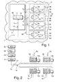
- Fig. 1 shows a transmit frontend 1 of a base station 2 for mobile radio communications being part of a radio network 3.
- the transmit frontend 1 may be adapted to perform radio transmissions according to one or more telecommunication standards, e.g. the UMTS (universal mobile telecommunications) or the LTE (long-term evolution) standard.
- UMTS universal mobile telecommunications
- LTE long-term evolution
- the transmit frontend 1 comprises a baseband part 4 which is connected (via cabling) to four active antenna elements 5a to 5d having identical construction. It will be understood that although four active antenna elements have been chosen in the present example, a higher or smaller number of active antenna elements may be used as well.
- Each active antenna element 5a to 5d comprises a signal processing device 6a to 6d for performing signal processing of a baseband signal 7a to 7d which is provided from the baseband part 4 to a respective one of the active antenna elements 5a to 5d.
- Each of the active antenna elements 5a to 5d also comprises an antenna 8a to 8d for radio transmission of an RF signal 7a' to 7d' which is generated by the signal processing device 6a to 6d by processing the baseband signal 7a to 7d.
- the array of four parallel antenna elements 5a to 5d may, for example, be used for supporting a MIMO scheme.
- the processing of the baseband signals 7a to 7d in the signal processing devices 6a to 6d will be exemplarily described for the first baseband signal 7a which is provided as a digital signal from the baseband part 4 to the first active antenna element 5a.
- the baseband signal 7a is D/A-converted and subsequently up-converted (shifted) to a carrier frequency in the GHz range.
- the up-converted signal is then provided as an input signal to a (power) amplifier 9a of the active antenna element 5a.
- the amplifier 9a may e.g. comprise a driver stage, a (transistor) switching stage and a reconstruction filter. As these amplifier components are known to those skilled in the art, no further explanation of their functionality will be given.
- the amplification of the up-converted baseband signals 7a to 7d in the amplifier units 9a to 9d leads to distortions of the amplified RF signals 7a' to 7d'.
- a linearization unit 11 is arranged in a digital signal processing unit 10 of the baseband part 4.
- the digital signal processing unit 10 further comprises a calibration unit 12 for calibrating the antenna elements 5a to 5d e.g. by adjusting timing delay differences between the different antenna elements 5a to 5d. The latter is particularly useful when MIMO transmissions are to be performed with the transmit antennas 8a to 8d.
- a feedback signal 13 is provided to the digital signal processing unit 10 via a feedback path 14, the generation of the feedback signal 13 being explained in the following with respect to Fig. 2 .
- each of the active antenna elements 5a to 5d has a measurement antenna element 15a to 15d associated therewith.
- the measurement antenna elements 15a to 15d are located close to the associated active antenna elements 5a to 5d for receiving only the RF signal 7a' to 7d' emitted by the associated antenna 8a to 8d. It will be understood that the measurement antennas 15a to 15d may be equipped with an (electrical) shielding for avoiding reception of RF signals emitted from adjacent antenna elements 5a to 5d.
- the feedback path 14 to the digital signal processing unit 10 also comprises a switch 16 allowing alternate connection of only one of the measurement antenna elements 15a to 15d to the feedback path 14.
- the feedback path 14 comprises a mixer 17 for down-conversion of the RF feedback signal from the measurement antenna elements 15a to 15d to an intermediate frequency or to the baseband.
- a filter 18 is provided for filtering unwanted frequency components of the feedback signal 13, the filter 18 being followed by an intermediate frequency (IF) or baseband amplifier 19.
- An analog-to-digital converter 20 then converts the amplified feedback signal 13 to the digital domain before it is provided to the digital signal processing unit 10.
- the digital signal processing unit 10 is adapted to provide the feedback signal 13 both to the linearization unit 11 and to the calibration unit 12. As has been explained above, although feedback from only one of the antenna elements 5a to 5d can be provided to the digital signal processing unit 10 at a time, this is sufficient for performing linearization of the amplification of the amplifiers 9a to 9d, resp., for performing delay adjustment of the antenna elements 5a to 5d. Thus, an effective way of providing feedback to the baseband part 4 can be provided.
- any block diagrams herein represent conceptual views of illustrative circuitry embodying the principles of the invention.
- any flow charts, flow diagrams, state transition diagrams, pseudo code, and the like represent various processes which may be substantially represented in computer readable medium and so executed by a computer or processor, whether or not such computer or processor is explicitly shown.
Landscapes
- Engineering & Computer Science (AREA)
- Computer Networks & Wireless Communication (AREA)
- Radio Transmission System (AREA)
Abstract
Description
- The invention relates to the field of telecommunications, and, more particularly, to transmit frontends for transmission of RF signals.
- This section introduces aspects that may be helpful in facilitating a better understanding of the invention. Accordingly, the statements of this section are to be read in this light and are not to be understood as admissions about what is in the prior art or what is not in the prior art.
- Base stations typically comprise a plurality of antenna elements for transmitting RF signals and a baseband part being connected to these antenna elements. The baseband part is adapted to generate so-called baseband signals (typically in the MHz range) and may also be adapted to perform up-conversion (mixing) of the baseband signals to generate RF signals at a carrier frequency, typically in the GHz range. Each RF signal is then provided to an amplifier before being fed to a respective transceiver antenna for RF transmission. The amplification (and possibly also the up-conversion) may be performed in so-called active antenna elements which are connected to the baseband part via cabling. The antenna elements together with the baseband part form a transmit frontend of the base station.
- Feedback about the amplified RF signals may be provided from the antenna elements back to the baseband part, thus allowing to perform (digital) pre-distortion of the baseband signals for linearization of the amplification and/or allowing to calibrate the antenna elements by adjusting time delay differences between the antenna elements. However, at present, no effective way of providing feedback to the baseband part is known.
- The present invention is directed to addressing the effects of one or more of the problems set forth above. The following presents a simplified summary of the invention in order to provide a basic understanding of some aspects of the invention. This summary is not an exhaustive overview of the invention. It is not intended to identify key or critical elements of the invention or to delineate the scope of the invention. Its sole purpose is to present some concepts in a simplified form as a prelude to the more detailed description that is discussed later.
- One aspect relates to a transmit frontend, in particular for a base station, comprising: a plurality of antenna elements being preferably devised as active antenna elements, each antenna element being adapted for transmitting an RF signal; a plurality of measurement antenna elements, each measurement antenna element being associated with one of the antenna elements for receiving a respective one of the RF signal; and a feedback path for providing a feedback signal from the measurement antenna elements to a baseband part of the transmit frontend.
- The inventors have found that using a single measurement antenna for a plurality of antenna elements of an antenna array / a base station does not produce a feedback signal which is accurate enough for adjusting the linearization / calibration of each amplifier / antenna element individually. Thus, the inventors propose to provide each antenna element with an associated measurement antenna element, the measurement antenna element being typically located close to the associated antenna element for avoiding interference with RF signals generated by other antenna elements of the base station. The feedback signal(s) thus generated is/are provided back to the baseband part, thus allowing an individual linearization / calibration of the different transceiver paths of the transmit fronted. The feedback path may comprise several parallel branches, each being devised for a feedback signal originating from a different antenna element.
- In a preferred embodiment, however, the transmit frontend further comprises a switching unit for alternate connection of the measurement antenna elements to the feedback path. In this case, the feedback signal is only available for a single antenna element at a time. However, this does not prevent efficient linearization / calibration of the individual amplifiers / antenna elements. As a feedback path typically requires a considerable amount of equipment for down-conversion of the RF signal (mixer, IF amplifier, etc.), using only a single feedback path for all antenna elements allows to provide feedback to the baseband part in a very cost-effective way.
- In a further embodiment, the baseband part comprises at least one calibration unit for calibrating at least one of the antenna elements based on the feedback signal from the associated measurement antenna element. The calibration performs adjusting timing delay differences between different antenna elements, the different antenna elements being preferably devised as an active antenna array. Two or more antennas of an antenna array may be used for performing MIMO transmissions, requiring an adequate adjustment of the timing of the different RF signals. Such an adjustment may be performed in the calibration unit based on the feedback signal.
- In a further embodiment, the baseband part comprises at least one linearization unit for linearization of an amplifier (unit) adapted for amplifying the RF signal to be transmitted by a respective antenna element, the linearization being based on the feedback signal from the associated measurement antenna element. Linearization of the amplification is typically performed by (digital) pre-distortion of the baseband signal, the pre-distortion being reciprocal to the distortion due to the amplifier. After Digital-to-Analogue- and up-conversion, a pre-distorted RF signal derived from the baseband signal is then provided as an input signal to the amplifier.
- In further embodiments, the transmit frontend comprises a mixing unit for down-conversion of the feedback signal and an A/D-converter for performing Analogue-to-Digital conversion of the feedback signal. A mixer may be used for converting the RF feedback signal received by the measurement antenna from its center frequency in the GHz range back to the baseband frequency range. However, the mixer can also be used for down-conversion of the RF feedback signal to an intermediate frequency (IF), the intermediate-frequency feedback signal being provided to the (digital) baseband part after A/D-conversion. It will be understood that filtering and/or amplification of the intermediate frequency feedback signal may be performed prior to A/D conversion.
- Further aspects relate to a base station and to a radio network comprising at least one transmit frontend as described above. Typically, the transmit frontend is implemented in a base station. However, it may also be possible to implement the transmit frontend in other wireless devices arranged in the radio network, e.g. in mobile phones or in PDAs.
- A further aspect relates to a method for providing a feedback signal to a baseband part of a transmit frontend which is devised e.g. in a base station, the method comprising: transmitting an RF signal from each of a plurality of antenna elements being preferably devised as active antenna elements; receiving the RF signal in one of a plurality of measurement antenna elements, each measurement antenna element being associated with a respective one of the antenna elements; and providing the feedback signal from the measurement antenna elements to the baseband part of the transmit frontend via a feedback path.
- In a preferred variant, only one of the measurement antenna elements is connected to the feedback path at a time. As in this case only a single feedback path is required, a cost-effective way of providing feedback to the baseband part can be realized.
- In a further variant, the method further comprises: using the feedback signal of the measurement antenna element for calibration of the associated antenna element. The calibration comprises the step of adjusting timing delay differences between different antenna elements which may be devised as an (active) antenna array. In such a way, synchronization of the different antennas of the antenna array can be performed, thus facilitating MIMO transmissions.
- In a further variant, the method further comprises: using the feedback signal of a measurement antenna element for linearization of an amplifier being adapted for amplifying the RF signal to be transmitted by the associated active antenna element. The linearization step preferably further comprises: performing digital pre-distortion of an input signal which is provided to the amplifier. Although digital pre-distortion has to be performed in a continuous way for allowing the linearization of the amplification in a respective amplifier, it is not necessary to continuously provide the feedback signal to the baseband part for performing the linearization, such that switching between the different measurement antennas may be performed.
- A further aspect of the invention relates to a computer program product adapted to perform all or at least some of the steps of the method described above. In particular, the computation of the digital pre-distortion of the baseband signal which is required for the linearization and/or the computation of the delay differences for the calibration may be performed in a digital signal processing unit arranged in the baseband part of the base station.
- Further features and advantages are stated in the following description of exemplary embodiments, with reference to the figures of the drawing, which shows significant details, and are defined by the claims. The individual features can be implemented individually by themselves, or several of them can be implemented in any desired combination.
- Exemplary embodiments are shown in the diagrammatic drawing and are explained in the description below. The following are shown:
- Fig. 1
- shows a schematic diagram of an embodiment of a transmit frontend according to the invention, and
- Fig. 2
- shows a detail of the transmit frontend of
Fig. 1 with a plurality of antenna elements and associated measurement antenna elements being alternately connected to a feedback path. - The functions of the various elements shown in the Figures, including any functional blocks labeled as 'processors', may be provided through the use of dedicated hardware as well as hardware capable of executing software in association with appropriate software. When provided by a processor, the functions may be provided by a single dedicated processor, by a single shared processor, or by a plurality of individual processors, some of which may be shared. Moreover, explicit use of the term 'processor' or 'controller' should not be construed to refer exclusively to hardware capable of executing software, and may implicitly include, without limitation, digital signal processor (DSP) hardware, network processor, application specific integrated circuit (ASIC), field programmable gate array (FPGA), read only memory (ROM) for storing software, random access memory (RAM), and non volatile storage. Other hardware, conventional and/or custom, may also be included. Similarly, any switches shown in the Figures are conceptual only. Their function may be carried out through the operation of program logic, through dedicated logic, through the interaction of program control and dedicated logic, or even manually, the particular technique being selectable by the implementer as more specifically understood from the context.
-
Fig. 1 shows a transmitfrontend 1 of abase station 2 for mobile radio communications being part of a radio network 3. The transmitfrontend 1 may be adapted to perform radio transmissions according to one or more telecommunication standards, e.g. the UMTS (universal mobile telecommunications) or the LTE (long-term evolution) standard. - The transmit
frontend 1 comprises abaseband part 4 which is connected (via cabling) to fouractive antenna elements 5a to 5d having identical construction. It will be understood that although four active antenna elements have been chosen in the present example, a higher or smaller number of active antenna elements may be used as well. Eachactive antenna element 5a to 5d comprises asignal processing device 6a to 6d for performing signal processing of abaseband signal 7a to 7d which is provided from thebaseband part 4 to a respective one of theactive antenna elements 5a to 5d. Each of theactive antenna elements 5a to 5d also comprises anantenna 8a to 8d for radio transmission of anRF signal 7a' to 7d' which is generated by thesignal processing device 6a to 6d by processing thebaseband signal 7a to 7d. The array of fourparallel antenna elements 5a to 5d may, for example, be used for supporting a MIMO scheme. - In the following, the processing of the baseband signals 7a to 7d in the
signal processing devices 6a to 6d will be exemplarily described for thefirst baseband signal 7a which is provided as a digital signal from thebaseband part 4 to the firstactive antenna element 5a. In thesignal processing device 6a, thebaseband signal 7a is D/A-converted and subsequently up-converted (shifted) to a carrier frequency in the GHz range. The up-converted signal is then provided as an input signal to a (power)amplifier 9a of theactive antenna element 5a. Theamplifier 9a may e.g. comprise a driver stage, a (transistor) switching stage and a reconstruction filter. As these amplifier components are known to those skilled in the art, no further explanation of their functionality will be given. - The person skilled in the art will appreciate that it is not necessary to perform the D/A-conversion, the mixing, and the amplification in the
antenna elements 5a to 5d, as it is also possible to perform part or the entire signal processing in thebaseband part 4. In the latter case, only thetransceiver antennas 8a to 8d are located remote from thebaseband part 4. - Typically, the amplification of the up-converted
baseband signals 7a to 7d in theamplifier units 9a to 9d leads to distortions of the amplifiedRF signals 7a' to 7d'. For providing linearization of the amplification by digital pre-distortion of the baseband signals 7a to 7d, alinearization unit 11 is arranged in a digitalsignal processing unit 10 of thebaseband part 4. The digitalsignal processing unit 10 further comprises acalibration unit 12 for calibrating theantenna elements 5a to 5d e.g. by adjusting timing delay differences between thedifferent antenna elements 5a to 5d. The latter is particularly useful when MIMO transmissions are to be performed with the transmitantennas 8a to 8d. - Both for the linearization of the
amplifiers 9a to 9d and for the calibration of theantenna elements 5a to 5d, afeedback signal 13 is provided to the digitalsignal processing unit 10 via afeedback path 14, the generation of thefeedback signal 13 being explained in the following with respect toFig. 2 . - As can be gathered from
Fig. 2 , each of theactive antenna elements 5a to 5d has ameasurement antenna element 15a to 15d associated therewith. Themeasurement antenna elements 15a to 15d are located close to the associatedactive antenna elements 5a to 5d for receiving only theRF signal 7a' to 7d' emitted by the associatedantenna 8a to 8d. It will be understood that themeasurement antennas 15a to 15d may be equipped with an (electrical) shielding for avoiding reception of RF signals emitted fromadjacent antenna elements 5a to 5d. - The
feedback path 14 to the digitalsignal processing unit 10 also comprises aswitch 16 allowing alternate connection of only one of themeasurement antenna elements 15a to 15d to thefeedback path 14. In the present example, thefeedback path 14 comprises amixer 17 for down-conversion of the RF feedback signal from themeasurement antenna elements 15a to 15d to an intermediate frequency or to the baseband. Following themixer 17, afilter 18 is provided for filtering unwanted frequency components of thefeedback signal 13, thefilter 18 being followed by an intermediate frequency (IF) orbaseband amplifier 19. An analog-to-digital converter 20 then converts the amplifiedfeedback signal 13 to the digital domain before it is provided to the digitalsignal processing unit 10. - The digital
signal processing unit 10 is adapted to provide thefeedback signal 13 both to thelinearization unit 11 and to thecalibration unit 12. As has been explained above, although feedback from only one of theantenna elements 5a to 5d can be provided to the digitalsignal processing unit 10 at a time, this is sufficient for performing linearization of the amplification of theamplifiers 9a to 9d, resp., for performing delay adjustment of theantenna elements 5a to 5d. Thus, an effective way of providing feedback to thebaseband part 4 can be provided. - It should be appreciated by those skilled in the art that any block diagrams herein represent conceptual views of illustrative circuitry embodying the principles of the invention. Similarly, it will be appreciated that any flow charts, flow diagrams, state transition diagrams, pseudo code, and the like represent various processes which may be substantially represented in computer readable medium and so executed by a computer or processor, whether or not such computer or processor is explicitly shown.
- Also, the description and drawings merely illustrate the principles of the invention. It will thus be appreciated that those skilled in the art will be able to devise various arrangements that, although not explicitly described or shown herein, embody the principles of the invention and are included within its scope. Furthermore, all examples recited herein are principally intended expressly to be only for pedagogical purposes to aid the reader in understanding the principles of the invention and the concepts contributed by the inventor(s) to furthering the art, and are to be construed as being without limitation to such specifically recited examples and conditions. Moreover, all statements herein reciting principles, aspects, and embodiments of the invention, as well as specific examples thereof, are intended to encompass equivalents thereof.
Claims (15)
- Transmit frontend (1), in particular for a base station (2), comprising:a plurality of antenna elements being preferably devised as active antenna elements (5a to 5d), each antenna element (5a to 5d) being adapted for transmitting an RF signal (7a' to 7d'),a plurality of measurement antenna elements (15a to 15d), each measurement antenna element (15a to 15d) being associated with one of the antenna elements (5a to 5d) for receiving a respective one of the RF signals (7a' to 7d'), anda feedback path (14) for providing a feedback signal (13) from the measurement antenna elements (15a to 15d) to a baseband part (4) of the transmit frontend (1).
- Transmit frontend according to claim 1, further comprising: a switching unit (16) for alternate connection of the measurement antenna elements (15a to 15d) to the feedback path (14).
- Transmit frontend according to claim 1 or 2, wherein the baseband part (4) comprises at least one calibration unit (11) for calibrating at least one of the antenna elements (5a to 5d) based on the feedback signal (13) from the associated measurement antenna element (15a to 15d).
- Transmit frontend according to claim 3, wherein the calibration unit (11) is adapted for adjusting timing delay differences between different antenna elements (5a to 5d), the different antenna elements (5a to 5d) being preferably devised as an antenna array.
- Transmit frontend according to any one of the preceding claims, wherein the baseband part (4) comprises at least one linearization unit (12) for linearization of an amplifier (9a to 9d) adapted for amplifying the RF signal (7a' to 7d') to be transmitted by a respective antenna element (5a to 5d), the linearization being based on the feedback signal (13) from the associated measurement antenna element (15a to 15d).
- Transmit frontend according to claim 5, wherein the linearization unit (12) is adapted for performing digital pre-distortion of an input signal (7a to 7d) to be provided to the amplifier (9a to 9d).
- Transmit frontend according to any one of the preceding claims, further comprising a mixing unit (17) for down-conversion of the feedback signal (13).
- Transmit frontend according to any one of the preceding claims, further comprising an analog-to-digital converter (20) for converting the analog feedback signal (13) into a digital feedback signal (13).
- Base station (2) comprising at least one transmit frontend (1) according to any one of the preceding claims.
- Radio network (3) comprising at least one base station (2) according to claim 9.
- Method for providing a feedback signal (13) to a baseband part (4) of a transmit frontend (1) of a base station (2), the method comprising:transmitting an RF signal (7a' to 7d') from each of a plurality of antenna elements which are preferably devised as active antenna elements (5a to 5d),receiving the RF signal (7a' to 7d') in one of a plurality of measurement antenna elements (15a to 15d), each measurement antenna element (15a to 15d) being associated with a respective one of the antenna elements (5a to 5d), andproviding the feedback signal (13) from the measurement antenna elements (15a to 15d) to the baseband part (4) of the transmit frontend (1) via a feedback path (14).
- Method according to claim 11, wherein only one of the measurement antenna elements (15a to 15d) at a time is connected to the feedback path (14).
- Method according to claim 11 or 12, further comprising: using the feedback signal (13) of the measurement antenna element (15a to 15d) for calibration of the associated antenna element (5a to 5d), the method preferably further comprising: adjusting timing delay differences between different antenna elements (5a to 5d), the different antenna elements (5a to 5d) being preferably devised as an antenna array.
- Method according to any one of claims 11 to 13, further comprising:using the feedback signal (13) of a measurement antenna element (15a to 15d) for linearization of an amplifier (9a to 9d) being adapted for amplifying the RF signal (7a' to 7d') to be transmitted by the associated active antenna element (5a to 5d), the linearization preferably further comprising: performing digital pre-distortion of an input signal (7a to 7d) which is provided to the amplifier (9a to 9d).
- Computer program product adapted to perform all the steps of the method according to any one of claims 11 to 14.
Priority Applications (1)
| Application Number | Priority Date | Filing Date | Title |
|---|---|---|---|
| EP20090290766 EP2309590A1 (en) | 2009-10-07 | 2009-10-07 | Transmit frontend with feedback for multiple antenna elements. |
Applications Claiming Priority (1)
| Application Number | Priority Date | Filing Date | Title |
|---|---|---|---|
| EP20090290766 EP2309590A1 (en) | 2009-10-07 | 2009-10-07 | Transmit frontend with feedback for multiple antenna elements. |
Publications (1)
| Publication Number | Publication Date |
|---|---|
| EP2309590A1 true EP2309590A1 (en) | 2011-04-13 |
Family
ID=41668466
Family Applications (1)
| Application Number | Title | Priority Date | Filing Date |
|---|---|---|---|
| EP20090290766 Withdrawn EP2309590A1 (en) | 2009-10-07 | 2009-10-07 | Transmit frontend with feedback for multiple antenna elements. |
Country Status (1)
| Country | Link |
|---|---|
| EP (1) | EP2309590A1 (en) |
Cited By (1)
| Publication number | Priority date | Publication date | Assignee | Title |
|---|---|---|---|---|
| WO2016034244A1 (en) * | 2014-09-05 | 2016-03-10 | Huawei Technologies Co.,Ltd | Base station controller for controlling a radio frequency emission of at least one antenna of a base station |
Citations (3)
| Publication number | Priority date | Publication date | Assignee | Title |
|---|---|---|---|---|
| WO2004025321A1 (en) * | 2002-09-11 | 2004-03-25 | Lockheed Martin Corporation | Cce calibration with an array of calibration probes interleaved with the array antenna |
| WO2004030147A1 (en) * | 2002-09-24 | 2004-04-08 | Nokia Corporation | Compensating for radiation pattern in radio system, and radio system |
| WO2004036691A1 (en) * | 2002-10-16 | 2004-04-29 | Electronics And Telecommunications Research Institute | Apparatus and method for linearizing adaptive array antenna system |
-
2009
- 2009-10-07 EP EP20090290766 patent/EP2309590A1/en not_active Withdrawn
Patent Citations (3)
| Publication number | Priority date | Publication date | Assignee | Title |
|---|---|---|---|---|
| WO2004025321A1 (en) * | 2002-09-11 | 2004-03-25 | Lockheed Martin Corporation | Cce calibration with an array of calibration probes interleaved with the array antenna |
| WO2004030147A1 (en) * | 2002-09-24 | 2004-04-08 | Nokia Corporation | Compensating for radiation pattern in radio system, and radio system |
| WO2004036691A1 (en) * | 2002-10-16 | 2004-04-29 | Electronics And Telecommunications Research Institute | Apparatus and method for linearizing adaptive array antenna system |
Cited By (2)
| Publication number | Priority date | Publication date | Assignee | Title |
|---|---|---|---|---|
| WO2016034244A1 (en) * | 2014-09-05 | 2016-03-10 | Huawei Technologies Co.,Ltd | Base station controller for controlling a radio frequency emission of at least one antenna of a base station |
| CN106664667A (en) * | 2014-09-05 | 2017-05-10 | 华为技术有限公司 | Base station controller for controlling a radio frequency emission of at least one antenna of a base station |
Similar Documents
| Publication | Publication Date | Title |
|---|---|---|
| EP3631979B1 (en) | Digital predistortion for advanced antenna system | |
| EP2987202B1 (en) | Antenna system calibration | |
| EP3285402B1 (en) | Phased array antenna device | |
| US10305183B2 (en) | Active antenna associated device and system, and transmitting and receiving calibration method | |
| EP3046260B1 (en) | Highly integrated radio frequency transceiver | |
| JP5051385B2 (en) | Wireless communication apparatus using array antenna, calibration method thereof, and wireless communication base station system | |
| KR101584372B1 (en) | Multi-dimensional Volterra series transmitter linearization | |
| JP5662669B2 (en) | Minimum feedback radio architecture with digitally configurable adaptive linearization | |
| CN103107966B (en) | Radiofrequency signal transmitting-receiving and the method processed, equipment and base station system | |
| US9859982B2 (en) | Distributed antenna system | |
| EP2845322B1 (en) | Radio communication apparatus and method | |
| US20110235734A1 (en) | Active antenna array having a single dpd lineariser and a method for predistortion of radio signals | |
| CN110999234A (en) | Method and apparatus for digital predistortion | |
| KR102298431B1 (en) | Predistortion processing method and apparatus | |
| US9236891B2 (en) | Radio communication transmitter apparatus and method | |
| KR20130103732A (en) | Apparatus and method for a multiband radio operating in a wireless network | |
| WO2015106802A1 (en) | Antenna calibration in communications | |
| KR102165072B1 (en) | Distributed antenna system and remote apparatus thereof | |
| KR20170018436A (en) | Transmitter and interference eliminating method | |
| KR102244582B1 (en) | Apparatus For Calibration of Active Array Antenna | |
| KR20090097295A (en) | TDD wireless communication system and method using digital predistortion method | |
| EP2309590A1 (en) | Transmit frontend with feedback for multiple antenna elements. | |
| EP3084972B1 (en) | Method and apparatus for common observation receiver for transmitter and receiver | |
| WO2013017965A1 (en) | Wireless long term evolution radio architecture system and method | |
| US9991994B1 (en) | Method and terminal device for reducing image distortion |
Legal Events
| Date | Code | Title | Description |
|---|---|---|---|
| PUAI | Public reference made under article 153(3) epc to a published international application that has entered the european phase |
Free format text: ORIGINAL CODE: 0009012 |
|
| 17P | Request for examination filed |
Effective date: 20100803 |
|
| AK | Designated contracting states |
Kind code of ref document: A1 Designated state(s): AT BE BG CH CY CZ DE DK EE ES FI FR GB GR HR HU IE IS IT LI LT LU LV MC MK MT NL NO PL PT RO SE SI SK SM TR |
|
| AX | Request for extension of the european patent |
Extension state: AL BA RS |
|
| RAP1 | Party data changed (applicant data changed or rights of an application transferred) |
Owner name: ALCATEL LUCENT |
|
| 111Z | Information provided on other rights and legal means of execution |
Free format text: AT BE BG CH CY CZ DE DK EE ES FI FR GB GR HR HU IE IS IT LI LT LU LV MC MK MT NL NO PL PT RO SE SI SK SM TR Effective date: 20130410 |
|
| RAP1 | Party data changed (applicant data changed or rights of an application transferred) |
Owner name: ALCATEL LUCENT |
|
| D11X | Information provided on other rights and legal means of execution (deleted) | ||
| STAA | Information on the status of an ep patent application or granted ep patent |
Free format text: STATUS: EXAMINATION IS IN PROGRESS |
|
| 17Q | First examination report despatched |
Effective date: 20170510 |
|
| STAA | Information on the status of an ep patent application or granted ep patent |
Free format text: STATUS: THE APPLICATION IS DEEMED TO BE WITHDRAWN |
|
| 18D | Application deemed to be withdrawn |
Effective date: 20170921 |