EP2309302A1 - Localization light emitting molecules of unknown orientation - Google Patents
Localization light emitting molecules of unknown orientation Download PDFInfo
- Publication number
- EP2309302A1 EP2309302A1 EP09172670A EP09172670A EP2309302A1 EP 2309302 A1 EP2309302 A1 EP 2309302A1 EP 09172670 A EP09172670 A EP 09172670A EP 09172670 A EP09172670 A EP 09172670A EP 2309302 A1 EP2309302 A1 EP 2309302A1
- Authority
- EP
- European Patent Office
- Prior art keywords
- marker
- light emitting
- entity
- focal plane
- images
- Prior art date
- Legal status (The legal status is an assumption and is not a legal conclusion. Google has not performed a legal analysis and makes no representation as to the accuracy of the status listed.)
- Withdrawn
Links
Images

Classifications
-
- G—PHYSICS
- G02—OPTICS
- G02B—OPTICAL ELEMENTS, SYSTEMS OR APPARATUS
- G02B21/00—Microscopes
- G02B21/0004—Microscopes specially adapted for specific applications
- G02B21/002—Scanning microscopes
- G02B21/0024—Confocal scanning microscopes (CSOMs) or confocal "macroscopes"; Accessories which are not restricted to use with CSOMs, e.g. sample holders
- G02B21/0052—Optical details of the image generation
- G02B21/0076—Optical details of the image generation arrangements using fluorescence or luminescence
-
- G—PHYSICS
- G01—MEASURING; TESTING
- G01N—INVESTIGATING OR ANALYSING MATERIALS BY DETERMINING THEIR CHEMICAL OR PHYSICAL PROPERTIES
- G01N21/00—Investigating or analysing materials by the use of optical means, i.e. using sub-millimetre waves, infrared, visible or ultraviolet light
- G01N21/62—Systems in which the material investigated is excited whereby it emits light or causes a change in wavelength of the incident light
- G01N21/63—Systems in which the material investigated is excited whereby it emits light or causes a change in wavelength of the incident light optically excited
- G01N21/64—Fluorescence; Phosphorescence
- G01N21/645—Specially adapted constructive features of fluorimeters
- G01N21/6456—Spatial resolved fluorescence measurements; Imaging
-
- G—PHYSICS
- G01—MEASURING; TESTING
- G01N—INVESTIGATING OR ANALYSING MATERIALS BY DETERMINING THEIR CHEMICAL OR PHYSICAL PROPERTIES
- G01N21/00—Investigating or analysing materials by the use of optical means, i.e. using sub-millimetre waves, infrared, visible or ultraviolet light
- G01N21/62—Systems in which the material investigated is excited whereby it emits light or causes a change in wavelength of the incident light
- G01N21/63—Systems in which the material investigated is excited whereby it emits light or causes a change in wavelength of the incident light optically excited
- G01N21/64—Fluorescence; Phosphorescence
- G01N21/645—Specially adapted constructive features of fluorimeters
- G01N2021/6463—Optics
Definitions
- the invention relates to a method of three-dimensionally localizing light emitting marker entities of unknown orientation in a sample, comprising the steps of the preamble of independent claim 1. Further, the invention relates to an apparatus for three-dimensionally localizing light emitting marker entities of unknown orientation, comprising the features of the preamble of claim 11. In an additional aspect the present invention relates to a method of localizing light emitting marker entities, comprising the steps of the preamble of independent claim 13.
- the light emitting marker entity may, for example, be a light emitting molecule or another small marker entity useable as a fluorescent dye, like, for example, a Quantum-dot.
- a method comprising the steps of the preamble of independent claim 1 and an apparatus comprising the features of the preamble of claim 11 are known from Manuel F. Juette et al.: "Three-dimensional sub-100 nm resolution fluorescence microscopy of thick samples" in Nature Methods, Vol. 5 No. 6, June 2008, p. 527-529 .
- This paper discloses a method named biplane (BP) FPALM which combines a double-plane detection scheme with fluorescence photoactivation localization microscopy (FPALM) enabling three-dimesional sub-diffraction resolution.
- BP biplane
- FPALM fluorescence photoactivation localization microscopy
- the z-position of the light emitting molecules is determined from the light intensity distributions over two detection planes onto which the light emitted by each single molecule is imaged and which correspond to two focal planes arranged at a known distance in z-direction.
- the emitted light intensity distributions over the different detection planes show different intensities and patterns allowing to determine the initially unknown z-position.
- the position of each single molecule is determined in a way generally known from methods including FPALM, PALM, Stochastic Optical Reconstruction Microscopy (STORM) and PALM with Independently Running Acquisition (PALMIRA).
- This way principally includes fitting a two-dimensional Gaussian intensity distribution to the detected intensity distributions over the detection plane and defining the centre of the Gaussian distribution as the position of the molecule in x- and y-directions.
- Manuel F. Juette et al. do not care for any effects due to dipole characteristics of the molecules in emitting light.
- DOPI allows for getting the centroid and the orientation of light emitting entities known to be located in a particular plane.
- the orientation of the marker entities is obtained from the emitted light intensity distribution of the defocused images of the marker entities; whereas their lateral position in the known plane is determined from the centre of the emitted light intensity distribution in the focussed image.
- the light emitting marker entities are either fluorophores, i.e. fluorescent molecules or quantum dots.
- the inventors Based on calculations and confirmed by actual measurements, the inventors have found that the dipole orientation of a light emitting marker entity in a sample which has an unknown axial position, i.e. an unknown z-position, may result in a centre of a two-dimensional Gaussian fit to the light intensity distribution of an image of the emitted light, which deviates by many 10 nm from the real lateral position, i.e. from the real x- and y-positions of the marker entity in the sample. This uncertainty is only present for defocused images of the marker entities. However, with an unknown z-position of the marker entities, a defocus of their images will be the norm.
- the uncertainties due to the unknown position in z-direction and the unknown orientation of the light emitting marker entities may result in totally wrong determinations of the distance between two marker entities with oppositely tilted dipole orientations.
- the uncertainty due to the unknown orientation of the marker entities is much higher than the spatial resolution in x- and y-directions claimed for standard methods of localizing light emitting marker entities in a sample like FPALM, PALM, STORM and PALMIRA. The inventors, however, found ways to resolve this uncertainty.
- the x- and y-positions of the marker entity determined from the emitted light intensity distribution over each image of the marker entity are only regarded as virtual x- and y-positions.
- These virtual x- and y-positions of the marker entity are separately determined from the emitted light intensity distribution over each single image of the marker entity, as these virtual x- and x-positions include valuable information on the real x-and y-positions of the marker entity in parallel to the focal plane.
- the real x- and y-positions of the marker entity in parallel to the focal plane can be determined based on its virtual x- and y-positions and on its z-position normal to the focal plane.
- This z-position may for example be determined according to the known BP FPALM-method in which each single marker entity is images onto at least two detection planes corresponding to at least two focal planes arranges at a known distance in the sample to provide the at least two images of each single marker entity.
- each single marker entity may be separately imaged via at least two different aperture regions of a same objective onto the same detection plane to provide for the at least two images.
- This alternative makes use of the fact that the difference between the virtual and the real x- and y-positions of a defocused marker entity depend on the N.A. of the objective used for imaging the marker entity.
- the real x- and y-positions of the marker entity in parallel to the focal plane may be extrapolated for its z-position normal to the focal plane from its virtual x- and y-positions.
- This extrapolation may simply be a linear one. Even such a simple linear extrapolation reduces the original uncertainty in the x- and y-positions of a light emitting marker entity of unknown orientation to just a small fraction of the original uncertainty.
- the virtual x- and y-positions determined from the emitted light intensity distribution over each image of the marker entity depend on the z-position of the marker entity, they include information on that z-position and may be accounted for in determining the z-position of the molecule normal to the focal plane.
- the main information on the z-position of the marker entities is included in the total or peak emitted light intensities in the images of the marker entities.
- these total or peak emitted light intensities are preferably accounted for in determining the z-position of the marker entity normal to the focal plane.
- both the absolute and the relative total or peak emitted light intensities include valuable information and may be evaluated.
- the absolute total or peak emitted light intensities may be compared with the absolute total or peak emitted light intensity of a light emitting marker intensity of a known defocus and orientation, particularly of a defocus of zero and a dipole orientation in the focal plane, and include information on the defocus and orientation of the actually imaged light emitting marker entity.
- the relative absolute total or peak emitted light intensities also include information on the defocus and orientation of the actually imaged light emitting marker entity, and point to the direction of the z-position of the light emitting marker entity with regard to the focal plane.
- both the real x- and y-positions and the z-position plus the dipole direction of the light emitting marker entity may be obtained from the images of the marker entity in that a function I(x,y,z, p ) is fitted to the emitted light intensity distributions in the images of the marker entity.
- the new method is particularly applicable in three-dimensionally localizing a plurality of light emitting marker entities of unknown orientation in the sample based on an overall emitted light intensity distributions over the at least one detection plane detected during one period of time.
- different pluralities of light emitting marker entities of unknown orientation in the sample which are selected by a statistical transfer process between a light emitting state and a no or other light emitting state of the marker entities, may be three-dimensionally localized based on several overall emitted light intensity distributions over the at least one detection plane detected during different periods of time.
- the new method may be integrated into any kind of FPALM, PALM, STORM and PALMIRA method.
- the alternative embodiment of the first new method indicated above requires a new apparatus comprising an objective imaging light emitted out of a sample onto a spatial light detector, which is characterized in that the light passing through at least two different aperture regions of the objective is focussed in at least two laterally offset points.
- the two images of each marker entity have a known basic offset in x- and/or y-direction.
- the deviations of the virtual x- and y-positions from the real x- and y-positions of the marker entity due to a defocus of the images, which also differ with the effective N.A. for the respective image, are superimposed with this basic offset.
- the new apparatus comprises an optical element dividing the aperture of the objective in a ring shaped outer region and a circular inner region and which causes a deflection of the light passing through one of these two regions with regard to the light passing through the other of the two regions.
- the second new method uses light emitting marker entities displaying no dipole characteristics in emitting light in localizing the light emitting marker entities with unknown orientation.
- these light emitting marker entities displaying no dipole characteristics in emitting light are selected from the group of light emitting marker entities transferable between a light emitting state and a no or other light emitting state to allow for imaging a structure marked by the marker entities according to the basic principles known from FPALM, PALM, STORM or PALMIRA.
- the light emitting marker entities may be selected from the group including nano diamond and Quantum-dot fluorescent dyes.
- Nano diamond fluorescent dyes display no dipole characteristic in emitting light
- quantum-dot fluorescent dyes are available in embodiments displaying no relevant dipole characteristics in emitting light.
- a Quantum-dot of symmetric construction in all spatial directions may, for example still have different emission properties in different spatial directions, but theses differences are only small and neglectible in localizing the Quantum-dot by the emitted light.
- Both nano diamond and Quantum-dot fluorescent dyes are known to have a long useable lifetime as compared to other fluorescent dyes, particularly as compared to other switchable fluorescent dyes.
- Fig. 1 consists of four pictures.
- the big one on the left hand side of Fig. 1 is a section in x- and z-direction through the emitted light intensity distribution of a dipole indicating the light intensities detectable at the different points in this x-z-plane having its origin in the centre of the dipole.
- the brighter a picture point of Fig. 1 the higher is the emitted light intensity which will be measured at that particular point.
- the light intensity distribution of Fig. 1 is for a dipole having a fixed orientation with a tilt angle of 45° with regard to the x-y-plane and for a fixed numerical aperture (N. A.) in measuring the light intensities.
- N. A. numerical aperture
- FIG. 1 depict three sections through the emitted light intensity distribution in x- and y-directions at three different levels in z-direction.
- the picture in the middle is a x-y-section through the centre of the dipole. It indicates the emitted light intensity distribution of a focused picture of the dipole.
- the centre of the light intensity distribution is the centre of the dipole in x- and y-direction.
- the upper and lower pictures on the right hand side of Fig. 1 correspond to defocused pictures of the dipole with a defocus of +200 nm and -200 nm, respectively.
- the centre of the emitted light intensity distribution is shifted by several 10 nm to the right and left, respectively.
- these centres of the emitted light intensity distribution may only be taken as virtual positions of the dipole in x- and y-directions and not as its real position.
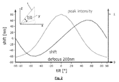
- Fig. 2 is a plot of the shift of the virtual position of the dipole in x- and y-direction with regard to its real position in images of the dipole at a fixed defocus of 200 nm versus the tilt angle of the dipole with regard to the x-y-plane between -90° and +90°.
- the maximum shift occurs at about +50° and -50° and amounts to 60 nm.
- the shift amounts to ⁇ 40 nm.
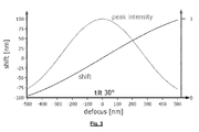
- the plot of Fig. 3 showing the shift of the virtual position of the imaged dipole in images of a varying defocus from -500 too +500 nm indicates that the shift about linearly varies with the defocus with a fixed tilt angle of the dipole with regard to the x-y-plane. This allows for a linear extrapolation of the virtual position of the dipole for a defocus of zero, where the shift is zero.
- the slope of the shift with regard to the defocus will be easily obtained from two images with a known difference in focus in axial- or z-direction.
- the real z-position of the dipole, at which the defocus would be zero may then be obtained from the absolute and relative peak emitted light intensities of the emitted light intensity distributions in the two images in combination with the slope of the shift.
- the real position of the dipole in x- and y-direction, the real position of the dipole in z-direction and the orientation of the dipole with regard to the x-y-plane and with regard to both the x- and y-direction may be obtained from the absolute and relative peak emitted light intensities of the emitted light intensity distributions in the two images in combination with the slope of the shift.
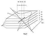
- Fig. 4 indicates five different focal planes 13 and the respective images 2 of the dipole, which is located in the middle focal plane 13, plus the peak emitted light intensity I(z) in the images 2 depending on the z-position of the focal plane 13.
- the virtual lateral positions of the images 2 of the dipole 1 are shifted by dx from focal plane 13 to focal plane 13 arranged at a distance dz.
- the peak emitted light intensity decreases from the middle plane toward the outer planes and the spot or image size increases.
- Evaluating all available data from at least two images in two of the focal planes indicated in Fig. 4 allows for determining the real z-position of the dipole and for extrapolating the x- and y-position of the dipole for this z-position. i.e. for determining the real x- and y-position of the dipole.
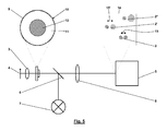
- Fig. 5 illustrates an apparatus comprising an objective 3 for imaging light emitted out of a sample 4 onto a spatial light detector 5, which may be a CCD-camera.
- the apparatus according to Fig. 5 further comprises a beam splitter 6 for coupling activation light from an activation light source 7 into the objective 3, and a tube lens 8.
- the most important part of the apparatus according to Fig. 5 is an optical element 9 defining two regions 11 and 12 of the numerical aperture 10 of the objective 3.
- the region 11 is a ring shaped outer zone of the aperture 10 having a higher effective N.A.
- the region 12 is a circular inner zone of the aperture 10 having a lower effective N.A.
- each light emitting object in the sample 4 imaged onto the spatial light detector 5 results in a double-image 2 with an offset 15 between its two partial images.
- An overall emitted light intensity distribution 14 detected with the spatial light detector 5 and depicted in Fig. 5 shows one double-image 2 of a light emitting dipole imaged in plane or in focus.
- the two partial images made up from the light passing through the different regions 11 und 12 of the aperture 13 display a basic offset 15 only due to the deflection, and, besides the offset 15, both partial images are essentially identical.
Landscapes
- Physics & Mathematics (AREA)
- Analytical Chemistry (AREA)
- General Physics & Mathematics (AREA)
- Health & Medical Sciences (AREA)
- Chemical & Material Sciences (AREA)
- Biochemistry (AREA)
- Life Sciences & Earth Sciences (AREA)
- General Health & Medical Sciences (AREA)
- Nuclear Medicine, Radiotherapy & Molecular Imaging (AREA)
- Immunology (AREA)
- Pathology (AREA)
- Optics & Photonics (AREA)
- Investigating, Analyzing Materials By Fluorescence Or Luminescence (AREA)
- Microscoopes, Condenser (AREA)
- Investigating Or Analysing Materials By Optical Means (AREA)
Abstract
To the end of three-dimensionally localizing light emitting marker entities of unknown orientation in a sample, the light emitted by each single marker entity is imaged in at least two different ways onto at least one detection plane which corresponds to a focal plane (13) in the sample resulting in at least two images of the marker entity. Virtual x- and y-positions of the marker entity in parallel to the focal plane (13) are separately determined from the emitted light intensity distribution over each image of the marker entity. Further, the z-position of the marker entity normal to the focal plane is determined from the emitted light intensity distributions over the images of the marker entity. The real x- and y-positions of the marker entity in parallel to the focal plane (13) are determined based on its virtual x- and y-positions and on its z-position normal to the focal plane.
Description
- The invention relates to a method of three-dimensionally localizing light emitting marker entities of unknown orientation in a sample, comprising the steps of the preamble of
independent claim 1. Further, the invention relates to an apparatus for three-dimensionally localizing light emitting marker entities of unknown orientation, comprising the features of the preamble ofclaim 11. In an additional aspect the present invention relates to a method of localizing light emitting marker entities, comprising the steps of the preamble ofindependent claim 13. - The light emitting marker entity may, for example, be a light emitting molecule or another small marker entity useable as a fluorescent dye, like, for example, a Quantum-dot.
- A method comprising the steps of the preamble of
independent claim 1 and an apparatus comprising the features of the preamble ofclaim 11 are known from Manuel F. Juette et al.: "Three-dimensional sub-100 nm resolution fluorescence microscopy of thick samples" in Nature Methods, Vol. 5 No. 6, June 2008, p. 527-529. This paper discloses a method named biplane (BP) FPALM which combines a double-plane detection scheme with fluorescence photoactivation localization microscopy (FPALM) enabling three-dimesional sub-diffraction resolution. The z-position of the light emitting molecules is determined from the light intensity distributions over two detection planes onto which the light emitted by each single molecule is imaged and which correspond to two focal planes arranged at a known distance in z-direction. Depending on the actual position of a particular single molecule in z-direction, the emitted light intensity distributions over the different detection planes show different intensities and patterns allowing to determine the initially unknown z-position. In x- and y-directions in parallel to the focal planes, the position of each single molecule is determined in a way generally known from methods including FPALM, PALM, Stochastic Optical Reconstruction Microscopy (STORM) and PALM with Independently Running Acquisition (PALMIRA). This way principally includes fitting a two-dimensional Gaussian intensity distribution to the detected intensity distributions over the detection plane and defining the centre of the Gaussian distribution as the position of the molecule in x- and y-directions. Manuel F. Juette et al. do not care for any effects due to dipole characteristics of the molecules in emitting light. - From Erdal Toprak et al.: "Defocused orientation and position imaging (DOPI) of myosin V" in PNAS, April 25, 2006, vol. 103 no. 17, p. 6495-6499, it is known that the centroid of a fluorophore can be determined within 1.5 nm accuracy from its focussed image through fluorescence imaging with one-nanometer accuracy (FIONA), and that, if, instead, the sample is moved away from the focus, the point-spread-function depends on both the position and three-dimensional orientation of the fluorophore, which can be calculated by defocused orientation and position imaging (DOPI). By switching back and forth between focussed and defocused imaging, DOPI allows for getting the centroid and the orientation of light emitting entities known to be located in a particular plane. The orientation of the marker entities is obtained from the emitted light intensity distribution of the defocused images of the marker entities; whereas their lateral position in the known plane is determined from the centre of the emitted light intensity distribution in the focussed image. The light emitting marker entities are either fluorophores, i.e. fluorescent molecules or quantum dots.
- From Jörg Enderlein et al.: "Polarization effect on position accuracy of fluorophore localization" in: OPTICS EXPRESS, Vol. 14, No. 18, September 2, 2006, p. 8111-8120, it is known that the intensity distribution of a light emitting molecule does not only depend on its position in space, but also on its three-dimensional orientation. Thus, the position determination usually done by fitting at two-dimensional Gaussian (x-y vs. photon number) to the emission intensity distribution may not result in the correct position of the light emitting molecule. In case of molecules placed in water on a glass surface, i.e. at a known z-position, the maximum shift of the centre position determined in this way using a 1.4 N.A. objective, however, was only 16 nm. With a smaller N.A. this position error should even be smaller as it is pointed out that the position accuracy for intermediate inclination angles of the dipole orientation of the light emitting molecules decreases with increasing N.A. Further, it is indicated that, if a dye is able to wobble around its attachment point during image exposure, thus emulating an isotropic emitter, the resulting image will be symmetric with respect to the actual position of the dye, and a 2-D Gaussian fitting will yield better FIONA accuracy than for any of the fixed dipole orientations. Jörg Enderlein et al. explicitly only regard conventional epi-fluoroscence microscopy and lateral positioning accuracy for molecules within the objective's focal plane. Studying the impact of molecule orientation on the position accuracy in other cases is told to be the topic of further studies.
- It is the problem of the invention to provide a method of three-dimensionally localizing light emitting marker entities of unknown orientation in a sample, comprising the steps of the preamble of
independent claim 1, an apparatus for three-dimensionally localizing light emitting molecules of unknown orientation in a sample, comprising the features of the preamble ofclaim 11, and a method of localizing light emitting marker entities in a sample, comprising the steps of the preamble ofindependent claim 13, which provide for accurate x- and y-positions of the marker entities in the sample independently of their actual orientation. - The problem of the invention is solved by a method comprising the steps of
claim 1, an apparatus comprising the features ofclaim 11, and a method comprising the steps ofclaim 13. - Based on calculations and confirmed by actual measurements, the inventors have found that the dipole orientation of a light emitting marker entity in a sample which has an unknown axial position, i.e. an unknown z-position, may result in a centre of a two-dimensional Gaussian fit to the light intensity distribution of an image of the emitted light, which deviates by many 10 nm from the real lateral position, i.e. from the real x- and y-positions of the marker entity in the sample. This uncertainty is only present for defocused images of the marker entities. However, with an unknown z-position of the marker entities, a defocus of their images will be the norm. Particularly, the uncertainties due to the unknown position in z-direction and the unknown orientation of the light emitting marker entities may result in totally wrong determinations of the distance between two marker entities with oppositely tilted dipole orientations. Particularly, the uncertainty due to the unknown orientation of the marker entities is much higher than the spatial resolution in x- and y-directions claimed for standard methods of localizing light emitting marker entities in a sample like FPALM, PALM, STORM and PALMIRA. The inventors, however, found ways to resolve this uncertainty.
- According to the first method of the present invention, the x- and y-positions of the marker entity determined from the emitted light intensity distribution over each image of the marker entity are only regarded as virtual x- and y-positions. These virtual x- and y-positions of the marker entity are separately determined from the emitted light intensity distribution over each single image of the marker entity, as these virtual x- and x-positions include valuable information on the real x-and y-positions of the marker entity in parallel to the focal plane. In fact, the real x- and y-positions of the marker entity in parallel to the focal plane can be determined based on its virtual x- and y-positions and on its z-position normal to the focal plane. This z-position may for example be determined according to the known BP FPALM-method in which each single marker entity is images onto at least two detection planes corresponding to at least two focal planes arranges at a known distance in the sample to provide the at least two images of each single marker entity.
- Alternatively, the light emitted by each single marker entity may be separately imaged via at least two different aperture regions of a same objective onto the same detection plane to provide for the at least two images. This alternative makes use of the fact that the difference between the virtual and the real x- and y-positions of a defocused marker entity depend on the N.A. of the objective used for imaging the marker entity.
- In both embodiments of the first new method, the real x- and y-positions of the marker entity in parallel to the focal plane may be extrapolated for its z-position normal to the focal plane from its virtual x- and y-positions. This extrapolation may simply be a linear one. Even such a simple linear extrapolation reduces the original uncertainty in the x- and y-positions of a light emitting marker entity of unknown orientation to just a small fraction of the original uncertainty.
- As the virtual x- and y-positions determined from the emitted light intensity distribution over each image of the marker entity depend on the z-position of the marker entity, they include information on that z-position and may be accounted for in determining the z-position of the molecule normal to the focal plane.
- The main information on the z-position of the marker entities, however, is included in the total or peak emitted light intensities in the images of the marker entities. Thus, these total or peak emitted light intensities are preferably accounted for in determining the z-position of the marker entity normal to the focal plane. Here, both the absolute and the relative total or peak emitted light intensities include valuable information and may be evaluated. The absolute total or peak emitted light intensities may be compared with the absolute total or peak emitted light intensity of a light emitting marker intensity of a known defocus and orientation, particularly of a defocus of zero and a dipole orientation in the focal plane, and include information on the defocus and orientation of the actually imaged light emitting marker entity. The relative absolute total or peak emitted light intensities also include information on the defocus and orientation of the actually imaged light emitting marker entity, and point to the direction of the z-position of the light emitting marker entity with regard to the focal plane.
- Further information on the z-position of the marker entities normal to the focal plane is included in emitted light intensity patterns in the images of the marker entities.
- Actually, both the real x- and y-positions and the z-position plus the dipole direction of the light emitting marker entity may be obtained from the images of the marker entity in that a function I(x,y,z, p ) is fitted to the emitted light intensity distributions in the images of the marker entity.
- The new method is particularly applicable in three-dimensionally localizing a plurality of light emitting marker entities of unknown orientation in the sample based on an overall emitted light intensity distributions over the at least one detection plane detected during one period of time. Even more particular, different pluralities of light emitting marker entities of unknown orientation in the sample, which are selected by a statistical transfer process between a light emitting state and a no or other light emitting state of the marker entities, may be three-dimensionally localized based on several overall emitted light intensity distributions over the at least one detection plane detected during different periods of time. I.e. the new method may be integrated into any kind of FPALM, PALM, STORM and PALMIRA method.
- Whereas an apparatus suitable for BP FPALM is also suitable for the embodiment of the first new method based on the known BP FPALM method, the alternative embodiment of the first new method indicated above requires a new apparatus comprising an objective imaging light emitted out of a sample onto a spatial light detector, which is characterized in that the light passing through at least two different aperture regions of the objective is focussed in at least two laterally offset points. Thus, the two images of each marker entity have a known basic offset in x- and/or y-direction. The deviations of the virtual x- and y-positions from the real x- and y-positions of the marker entity due to a defocus of the images, which also differ with the effective N.A. for the respective image, are superimposed with this basic offset.
- In a particular embodiment, the new apparatus comprises an optical element dividing the aperture of the objective in a ring shaped outer region and a circular inner region and which causes a deflection of the light passing through one of these two regions with regard to the light passing through the other of the two regions.
- The second new method uses light emitting marker entities displaying no dipole characteristics in emitting light in localizing the light emitting marker entities with unknown orientation. Particularly, these light emitting marker entities displaying no dipole characteristics in emitting light are selected from the group of light emitting marker entities transferable between a light emitting state and a no or other light emitting state to allow for imaging a structure marked by the marker entities according to the basic principles known from FPALM, PALM, STORM or PALMIRA.
- Even more particularly, the light emitting marker entities may be selected from the group including nano diamond and Quantum-dot fluorescent dyes. Nano diamond fluorescent dyes display no dipole characteristic in emitting light, and quantum-dot fluorescent dyes are available in embodiments displaying no relevant dipole characteristics in emitting light. A Quantum-dot of symmetric construction in all spatial directions, may, for example still have different emission properties in different spatial directions, but theses differences are only small and neglectible in localizing the Quantum-dot by the emitted light. Both nano diamond and Quantum-dot fluorescent dyes are known to have a long useable lifetime as compared to other fluorescent dyes, particularly as compared to other switchable fluorescent dyes.
- Advantageous developments of the invention result from the claims, the description and the drawings. The advantages of features and of combinations of a plurality of features mentioned at the beginning of the description only serve as examples and may be used alternatively or cumulatively without the necessity of embodiments according to the invention having to obtain these advantages. Further features may be taken from the drawings, in particular from the illustrated designs and the dimensions of a plurality of components with respect to one another as well as from their relative arrangement and their operative connection. The combination of features of different embodiments of the invention or of features of different claims independent of the chosen references of the claims is also possible, and it is motivated herewith. This also relates to features which are illustrated in separate drawings, or which are mentioned when describing them. These features may also be combined with features of different claims. Furthermore, it is possible that further embodiments of the invention do not have the features mentioned in the claims.
- In the following the invention as further described with reference to the accompanied drawings.
- Fig. 1
- is a section in x- and z-direction through an intensity distribution of light emitted by a dipole tilted by 45° with regard to the x-direction and running orthogonal to the y-direction which is normal to the drawing plane. Further,
Fig. 1 shows three different sections in x- and y-direction through the emitted light intensity distribution. These three sections correspond to images of the light emitted by the dipole and imaged on different detection planes corresponding to different focal planes arranged at distances in z-direction. - Fig. 2
- is a plot of the virtual shift of a dipole tilted with regard to the x-y-plane by different angles from -90° to 90° when imaged with a defocus of 200 nm. Further,
Fig. 2 indicates the peak intensity of the emitted light intensity distribution in the respective images of the dipole. - Fig. 3
- is a plot of the virtual shift of the position of the dipole at a fixed tilt of 30° with regard to the x-y-plane versus a defocus of the images of the dipole from -500 to +500 nm. Further,
Fig. 3 indicates the peak intensity of the emitted light intensity distribution in the respective images of the dipole. - Fig. 4
- indicates how multi focal plane imaging of a dipole allow for determining its real position in x- and y-direction based on the light intensity distributions detected in defocused images of the dipole; and
- Fig. 5
- indicates the new apparatus according to the invention and the embodiment of the new method executed with this apparatus in which different numerical apertures are used to visualize the virtual shift in position of an imaged dipole tilted at an angle with regard to the x-y-plane.
-
Fig. 1 consists of four pictures. The big one on the left hand side ofFig. 1 is a section in x- and z-direction through the emitted light intensity distribution of a dipole indicating the light intensities detectable at the different points in this x-z-plane having its origin in the centre of the dipole. The brighter a picture point ofFig. 1 , the higher is the emitted light intensity which will be measured at that particular point. The light intensity distribution ofFig. 1 is for a dipole having a fixed orientation with a tilt angle of 45° with regard to the x-y-plane and for a fixed numerical aperture (N. A.) in measuring the light intensities. The three smaller pictures at the right hand side ofFig. 1 depict three sections through the emitted light intensity distribution in x- and y-directions at three different levels in z-direction. The picture in the middle is a x-y-section through the centre of the dipole. It indicates the emitted light intensity distribution of a focused picture of the dipole. Here, the centre of the light intensity distribution is the centre of the dipole in x- and y-direction. The upper and lower pictures on the right hand side ofFig. 1 , however, correspond to defocused pictures of the dipole with a defocus of +200 nm and -200 nm, respectively. Here, the centre of the emitted light intensity distribution is shifted by several 10 nm to the right and left, respectively. Thus, these centres of the emitted light intensity distribution may only be taken as virtual positions of the dipole in x- and y-directions and not as its real position. -
Fig. 2 is a plot of the shift of the virtual position of the dipole in x- and y-direction with regard to its real position in images of the dipole at a fixed defocus of 200 nm versus the tilt angle of the dipole with regard to the x-y-plane between -90° and +90°. The maximum shift occurs at about +50° and -50° and amounts to 60 nm. One may argue that such large shifts only occur with images showing a low peak intensity also depicted inFig. 2 . However, even with peak intensities of ≥ 50 % of the maximum peak intensity, the shift amounts to ±40 nm. - The plot of
Fig. 3 showing the shift of the virtual position of the imaged dipole in images of a varying defocus from -500 too +500 nm indicates that the shift about linearly varies with the defocus with a fixed tilt angle of the dipole with regard to the x-y-plane. This allows for a linear extrapolation of the virtual position of the dipole for a defocus of zero, where the shift is zero. The slope of the shift with regard to the defocus will be easily obtained from two images with a known difference in focus in axial- or z-direction. The real z-position of the dipole, at which the defocus would be zero may then be obtained from the absolute and relative peak emitted light intensities of the emitted light intensity distributions in the two images in combination with the slope of the shift. As a result, one will obtain the real position of the dipole in x- and y-direction, the real position of the dipole in z-direction and the orientation of the dipole with regard to the x-y-plane and with regard to both the x- and y-direction. - This method of determining the real position of a tilted dipole from at least two
images 2 of thedipole 1 with twofocal planes 13 at a known distance in the space of thedipole 1 is also illustrated inFig. 4. Fig. 4 indicates five differentfocal planes 13 and therespective images 2 of the dipole, which is located in the middlefocal plane 13, plus the peak emitted light intensity I(z) in theimages 2 depending on the z-position of thefocal plane 13. The virtual lateral positions of theimages 2 of thedipole 1 are shifted by dx fromfocal plane 13 tofocal plane 13 arranged at a distance dz. At the same time the peak emitted light intensity decreases from the middle plane toward the outer planes and the spot or image size increases. Evaluating all available data from at least two images in two of the focal planes indicated inFig. 4 allows for determining the real z-position of the dipole and for extrapolating the x- and y-position of the dipole for this z-position. i.e. for determining the real x- and y-position of the dipole. -
Fig. 5 illustrates an apparatus comprising anobjective 3 for imaging light emitted out of a sample 4 onto a spatiallight detector 5, which may be a CCD-camera. The apparatus according toFig. 5 further comprises abeam splitter 6 for coupling activation light from anactivation light source 7 into theobjective 3, and atube lens 8. However, the most important part of the apparatus according toFig. 5 is an optical element 9 defining tworegions numerical aperture 10 of theobjective 3. Theregion 11 is a ring shaped outer zone of theaperture 10 having a higher effective N.A., and theregion 12 is a circular inner zone of theaperture 10 having a lower effective N.A. Theregions light detector 5 results in a double-image 2 with an offset 15 between its two partial images. An overall emittedlight intensity distribution 14 detected with the spatiallight detector 5 and depicted inFig. 5 shows one double-image 2 of a light emitting dipole imaged in plane or in focus. Here, the two partial images made up from the light passing through thedifferent regions 11 und 12 of theaperture 13 display a basic offset 15 only due to the deflection, and, besides the offset 15, both partial images are essentially identical.Further images 2' and 2", however, show increased offsets 15', and different partial images due to the different effective numerical apertures of theregions image 2 of each light emitting dipole, including an account for the relative and/or absolute total or peak emitted light intensities, allows for determining the real x-, y- and z-positions of the dipole plus its tilt angle. -
- 1
- dipole
- 2
- image
- 3
- objective
- 4
- sample
- 5
- spatial light detector
- 6
- beam splitter
- 7
- activation light source
- 8
- tube lens
- 9
- optical element
- 10
- aperture
- 11
- region
- 12
- region
- 13
- focal plane
- 14
- overall emitted light intensity distribution
- 15
- offset
Claims (15)
- Method of three-dimensionally localizing light emitting marker entities of unknown orientation in a sample (4), wherein the light emitted by each single marker entity is imaged in at least two different ways onto at least one detection plane which corresponds to a focal plane (13) in the sample (4) resulting in at least two images (2) of the marker entity, and wherein the x- and y-positions of the marker entity in parallel to the focal plane (13) and the z-position of the marker entity normal to the focal plane (13) are determined from the emitted light intensity distributions over the images (2) of the marker entity, characterized in that virtual x- and y-positions of the marker entity are separately determined from the emitted light intensity distribution over each image (2) of the marker entity, and that the real x- and y-positions of the marker entity in parallel to the focal plane (13) are determined based on its virtual x- and y-positions and on its z-position normal to the focal plane (13).
- Method of claim 1, characterized in that the real x- and y-positions of the marker entity in parallel to the focal plane (13) are extrapolated for its z-position normal to the focal plane from its virtual x- and y-positions.
- Method of claim 2, characterized in that the virtual x- and y-positions determined from the emitted light intensity distribution over the images (2) of the marker entity are accounted for in determining the z-position of the molecule normal to the focal plane (13).
- Method of any of the claims 1 to 3, characterized in that the absolute and/or relative total or peak emitted light intensities in the images (2) of the marker entity are accounted for in determining the z-position of the marker entity normal to the focal plane (13).
- Method of any of the claims 1 to 4, characterized in that emitted light intensity patterns in the images of the marker entity are accounted for in determining the z-position of the marker entity normal to the focal plane (13).
- Method of any of the claims 1 to 5, characterized in that a function I(x,y,z, p ) is fitted to the emitted light intensity distributions over the images (2) of the marker entity, wherein p is the dipole direction of the light emitting marker entity.
- Method of any of the claims 1 to 6, characterized in that a plurality of light emitting marker entities of unknown orientation in the sample (4) is three-dimensionally localized based on an overall emitted light intensity distribution over the at least one detection plane detected during one period of time.
- Method of claim 7, characterized in that different pluralities of light emitting marker entities of unknown orientation in the sample (4), which are selected by a statistical transfer process between a light emitting state and a no or other light emitting state of the marker entities, are localized based on several overall emitted light intensity distributions over the at least one detection plane detected during different periods of time.
- Method of any of the claims 1 to 8, characterized in that each single marker entity is imaged onto at least two detection planes corresponding to at least two focal planes (13) arranged at a known distance in the sample (4) to provide the at least two images (2).
- Method of any of the claims 1 to 8, characterized in that the light emitted by each single marker entity is separately imaged via at least two different aperture regions (11, 12) of a same objective (3) onto the at least one detection plane to provide for the at least two images (2).
- Apparatus for three-dimensionally localizing light emitting entities of unknown orientation in a sample (4) according to the method of claim 10, comprising an objective (3) imaging the light emitted out of the sample (4) on a spatial light detector (5), characterized in that the light passing through at least two different aperture regions (11, 12) of the objective (3) is focussed in at least two laterally offset images (2).
- Apparatus of claim 11, characterized in that an optical element (9) divides the aperture (10) of the objective (3) in a ring shaped outer region (11) and a circular inner region (12) and causes deflection of the light passing through one of these two regions (11, 12) with regard to the light passing through the other of these two regions (12, 11).
- Method of localizing light emitting marker entities of unknown orientation in a sample (4), wherein the light emitted by each single marker entity is imaged onto at least one detection plane corresponding to a focal plane (13) in the sample (4), and wherein the the x- and y-positions of the marker entity in parallel to the focal plane (13) are determined from the emitted light intensity distributions over the detection plane, characterized in that the light emitting marker entities are selected from the group of light emitting marker entities which display no dipole characteristics in emitting light.
- Method of claim 13, characterized in that the light emitting marker entities are selected from the group of light emitting marker entities transferable between a light emitting state and a no or other light emitting state.
- Method of claim 14, characterized in that the light emitting marker entities are selected from the group including nano diamond and Quantum-dot fluorescent dyes.
Priority Applications (4)
| Application Number | Priority Date | Filing Date | Title |
|---|---|---|---|
| EP09172670A EP2309302A1 (en) | 2009-10-09 | 2009-10-09 | Localization light emitting molecules of unknown orientation |
| PCT/EP2010/064989 WO2011042493A1 (en) | 2009-10-09 | 2010-10-07 | Three-dimensionally localizing light emitting molecules of unknown orientation and unknown z-position |
| EP10762678.0A EP2486438B1 (en) | 2009-10-09 | 2010-10-07 | Three-dimensionally localizing light emitting molecules of unknown orientation and unknown z-position |
| US13/441,043 US8559021B2 (en) | 2009-10-09 | 2012-04-06 | Three-dimensionally localizing light emitting molecules of unknown orientation and unknown Z-position |
Applications Claiming Priority (1)
| Application Number | Priority Date | Filing Date | Title |
|---|---|---|---|
| EP09172670A EP2309302A1 (en) | 2009-10-09 | 2009-10-09 | Localization light emitting molecules of unknown orientation |
Publications (1)
| Publication Number | Publication Date |
|---|---|
| EP2309302A1 true EP2309302A1 (en) | 2011-04-13 |
Family
ID=41611369
Family Applications (2)
| Application Number | Title | Priority Date | Filing Date |
|---|---|---|---|
| EP09172670A Withdrawn EP2309302A1 (en) | 2009-10-09 | 2009-10-09 | Localization light emitting molecules of unknown orientation |
| EP10762678.0A Not-in-force EP2486438B1 (en) | 2009-10-09 | 2010-10-07 | Three-dimensionally localizing light emitting molecules of unknown orientation and unknown z-position |
Family Applications After (1)
| Application Number | Title | Priority Date | Filing Date |
|---|---|---|---|
| EP10762678.0A Not-in-force EP2486438B1 (en) | 2009-10-09 | 2010-10-07 | Three-dimensionally localizing light emitting molecules of unknown orientation and unknown z-position |
Country Status (3)
| Country | Link |
|---|---|
| US (1) | US8559021B2 (en) |
| EP (2) | EP2309302A1 (en) |
| WO (1) | WO2011042493A1 (en) |
Cited By (1)
| Publication number | Priority date | Publication date | Assignee | Title |
|---|---|---|---|---|
| WO2021063865A1 (en) * | 2019-09-30 | 2021-04-08 | Universite D'aix-Marseille | Devices and methods for the characterization of the 3d orientation of light emitting dipoles |
Families Citing this family (3)
| Publication number | Priority date | Publication date | Assignee | Title |
|---|---|---|---|---|
| WO2015151812A1 (en) * | 2014-04-03 | 2015-10-08 | 株式会社日立ハイテクノロジーズ | Fluorometric analyzer |
| WO2019170757A2 (en) | 2018-03-07 | 2019-09-12 | LIFE TECHNOLOGIES GmbH | Imaging apparatuses, systems and methods |
| KR102592426B1 (en) * | 2019-01-02 | 2023-10-23 | 삼성디스플레이 주식회사 | Ink-jet printing apparatus, method of aligning dipoles and method of fabricating display device |
Family Cites Families (20)
| Publication number | Priority date | Publication date | Assignee | Title |
|---|---|---|---|---|
| US1957371A (en) * | 1933-12-05 | 1934-05-01 | William M Thomas | Lens structure with prisms |
| SU699470A1 (en) * | 1978-03-31 | 1979-11-25 | Предприятие П/Я В-8450 | Diaphragm for reflex objective lens |
| FR2532756A1 (en) * | 1982-09-03 | 1984-03-09 | France Henri De | SYSTEM FOR AUTOMATIC OBSERVATION AND QUANTIFICATION OF PHENOMENA THAT CAN BE DETECTED BY FLUORESCENCE |
| DE3406578C2 (en) * | 1983-02-24 | 1985-09-05 | Olympus Optical Co., Ltd., Tokio/Tokyo | Automatic focus detection device |
| US4916473A (en) * | 1985-08-14 | 1990-04-10 | Minolta Camera Kabushiki Kaisha | Focus detection apparatus |
| JPH07117645B2 (en) * | 1987-12-14 | 1995-12-18 | キヤノン株式会社 | Focus detection device |
| US5349592A (en) * | 1992-02-27 | 1994-09-20 | Kabushiki Kaisha Toshiba | Super-resolution optical element for use in image forming apparatus |
| US5861987A (en) * | 1994-08-30 | 1999-01-19 | Olympus Optical Co., Ltd. | Stereoscopic-vision endoscope offering a large angle of introversion and a necessary and sufficient sense of three-dimensionality |
| JPH10177738A (en) * | 1996-12-17 | 1998-06-30 | Sankyo Seiki Mfg Co Ltd | Optical pickup device |
| JP3566504B2 (en) * | 1997-07-18 | 2004-09-15 | 日本放送協会 | Optical device for 2-aperture bifocal light reproduction |
| TW368650B (en) * | 1998-02-19 | 1999-09-01 | Ind Tech Res Inst | Prism object lens of optical pickup head |
| US20020114077A1 (en) * | 2001-01-23 | 2002-08-22 | Bahram Javidi | Integral three-dimensional imaging with digital reconstruction |
| US7889905B2 (en) * | 2005-05-23 | 2011-02-15 | The Penn State Research Foundation | Fast 3D-2D image registration method with application to continuously guided endoscopy |
| WO2008079301A2 (en) * | 2006-12-21 | 2008-07-03 | Massachusetts Institute Of Technology | Methods and apparatus for 3d surface imaging using active wave-front sampling |
| US7872796B2 (en) * | 2007-01-25 | 2011-01-18 | Adobe Systems Incorporated | Light field microscope with lenslet array |
| US8227735B1 (en) * | 2007-07-24 | 2012-07-24 | Lockheed Martin Coherent Technologies, Inc. | Combined active and passive imaging system with radiation source unit and detector |
| WO2010141608A1 (en) * | 2009-06-02 | 2010-12-09 | Imflux Llc | Superresolution optical fluctuation imaging (sofi) |
| JP5495683B2 (en) * | 2009-09-10 | 2014-05-21 | キヤノン株式会社 | Imaging apparatus and distance measuring method |
| JP5178678B2 (en) * | 2009-09-30 | 2013-04-10 | キヤノン株式会社 | Imaging system and lens device |
| EP3136079B1 (en) * | 2009-10-20 | 2020-02-12 | The Regents of The University of California | Incoherent lensfree cell holography and microscopy on a chip |
-
2009
- 2009-10-09 EP EP09172670A patent/EP2309302A1/en not_active Withdrawn
-
2010
- 2010-10-07 EP EP10762678.0A patent/EP2486438B1/en not_active Not-in-force
- 2010-10-07 WO PCT/EP2010/064989 patent/WO2011042493A1/en not_active Ceased
-
2012
- 2012-04-06 US US13/441,043 patent/US8559021B2/en not_active Expired - Fee Related
Non-Patent Citations (10)
| Title |
|---|
| ALIPASHA VAZIRI: "Multilayer three-dimensional super resolution imaging of thick biological samples", PNAS, vol. 105, no. 51, 23 December 2008 (2008-12-23), pages 20221 - 20226, XP002568452 * |
| E. TOPRAK ET AL.: "Defocused orientation and position imaging (DOPI) of myosin V", PNAS, vol. 103, no. 17, 25 April 2006 (2006-04-25), pages 6495 - 6499, XP002568435 * |
| ERDAL TOPRAK ET AL.: "Defocused orientation and position imaging (DOPI) of myosin V", PNAS, vol. 103, no. 17, 25 April 2006 (2006-04-25), pages 6495 - 6499 |
| J. ENDERLEIN ET AL.: "Polarization effect on position accuracy of fluorophore localization", OPTICS EXPRESS, vol. 14, no. 18, 4 September 2006 (2006-09-04), pages 8111, XP002568449 * |
| JORG ENDERLEIN ET AL.: "Polarization effect on position accuracy of fluorophore localization", OPTICS EXPRESS, vol. 14, no. 18, 2 September 2006 (2006-09-02), pages 8111 - 8120 |
| JUETTE M F ET AL: "Three-dimensional sub-100 nm resolution fluorescence microscopy of thick samples", NATURE METHODS, NATURE PUBLISHING GROUP, GB, vol. 5, no. 6, 1 June 2008 (2008-06-01), pages 527 - 529, XP002523348, ISSN: 1548-7091, [retrieved on 20080511] * |
| MANUEL F. JUETTE ET AL.: "Three-dimensional sub-100 nm resolution fluorescence microscopy of thick samples", NATURE METHODS, vol. 5, no. 6, June 2008 (2008-06-01), pages 527 - 529 |
| MARTA FERNÁNDEZ-SUÁREZ AND ALICE Y. TING: "Fluorescent probes for super-resolution imaging in living cells", NATURE REVIEWS MOLECULAR CELL BIOLOGY, vol. 9, December 2008 (2008-12-01), pages 929 - 943, XP002582391, DOI: 10.1038/nrm2531 * |
| MICHAEL J. MLODZIANOSKI, MANUEL F. JUETTE, GLEN L. BEANE, AND JOERG BEWERSDORF: "Experimental characterization of 3D localization techniques for particle-tracking and super-resolution microscopy", OPTICS EXPRESS, vol. 17, no. 10, 11 May 2009 (2009-05-11), pages 8264 - 8277, XP002568448 * |
| SCOTT E. IRVINE, DR. , THORSTEN STAUDT , EVA RITTWEGER , JOHANN ENGELHARDT, DR. , STEFAN W. HELL, PROF. DR.: "Direct Light-Driven Modulation of Luminescence from Mn-Doped ZnSe Quantum Dots", ANGEWANDTE CHEMIE INTERNATIONAL EDITION, vol. 47, no. 14, 27 February 2008 (2008-02-27), pages 2685 - 2688, XP002582392, DOI: 10.1002/anie.200705111 * |
Cited By (2)
| Publication number | Priority date | Publication date | Assignee | Title |
|---|---|---|---|---|
| WO2021063865A1 (en) * | 2019-09-30 | 2021-04-08 | Universite D'aix-Marseille | Devices and methods for the characterization of the 3d orientation of light emitting dipoles |
| US11927737B2 (en) | 2019-09-30 | 2024-03-12 | Université D'aix-Marseille | Devices and methods for the characterization of the 3D orientation of light emitting dipoles |
Also Published As
| Publication number | Publication date |
|---|---|
| WO2011042493A1 (en) | 2011-04-14 |
| EP2486438B1 (en) | 2019-01-16 |
| US8559021B2 (en) | 2013-10-15 |
| US20120212750A1 (en) | 2012-08-23 |
| EP2486438A1 (en) | 2012-08-15 |
Similar Documents
| Publication | Publication Date | Title |
|---|---|---|
| US9179131B2 (en) | Microscopic device and method for three-dimensional localization of point-like objects in a specimen | |
| US9720221B2 (en) | Device and method for acquiring a microscopic image of a sample structure | |
| Scheckenbach et al. | DNA origami nanorulers and emerging reference structures | |
| US8345941B2 (en) | Biological imaging device | |
| US6424421B1 (en) | Method and devices for measuring distances between object structures | |
| US7342717B1 (en) | Wave field microscope with detection point spread function | |
| CN101821608B (en) | Method and system for imaging a sample | |
| EP2896061B1 (en) | Integrated optical and charged particle inspection apparatus | |
| US20220276125A1 (en) | Optical imaging performance test system and method | |
| US6798569B2 (en) | Microscope and method for operating a microscope | |
| CN109844503A (en) | Method for determining with high spatial resolution the location of isolated molecules excitable with excitation light to emit luminescence in a sample | |
| US10234672B2 (en) | Light-microscopic method of localization microscopy for localizing point objects | |
| EP3762758B1 (en) | Imaging apparatuses, systems and methods | |
| EP2831657B1 (en) | Improved confocal microscopy methods and devices | |
| US8559021B2 (en) | Three-dimensionally localizing light emitting molecules of unknown orientation and unknown Z-position | |
| CN105278090B (en) | The method that fluid for being adhered to microtiter plate fills the microscope imaging of the sample on the bottom of well | |
| Moosmayer et al. | MINFLUX fluorescence nanoscopy in biological tissue | |
| DE19830596B4 (en) | Wave field microscope, wave field microscopy method, also for DNA sequencing, and calibration method for wave field microscopy | |
| US7474393B2 (en) | Method and apparatus for determining a vertical intensity profile along an illuminating beam | |
| Erdélyi et al. | Origin and compensation of imaging artefacts in localization-based super-resolution microscopy | |
| JP6659531B2 (en) | Optical microscopy for localization of point objects | |
| Hibbs et al. | Practical confocal microscopy | |
| JP5385442B2 (en) | Microscope objective lens and fluorescence observation apparatus using the same | |
| DE102023118695B4 (en) | Method, localization microscope and computer program for localizing or tracking individual emitters in a sample | |
| Edelmann et al. | Correlation of chromatic shifts and focal depth in spectral precision distance microscopy measured by microaxial tomography |
Legal Events
| Date | Code | Title | Description |
|---|---|---|---|
| PUAI | Public reference made under article 153(3) epc to a published international application that has entered the european phase |
Free format text: ORIGINAL CODE: 0009012 |
|
| AK | Designated contracting states |
Kind code of ref document: A1 Designated state(s): AT BE BG CH CY CZ DE DK EE ES FI FR GB GR HR HU IE IS IT LI LT LU LV MC MK MT NL NO PL PT RO SE SI SK SM TR |
|
| AX | Request for extension of the european patent |
Extension state: AL BA RS |
|
| RTI1 | Title (correction) |
Free format text: LOCALIZING LIGHT EMITTING MOLECULES OF UNKNOWN ORIENTATION |
|
| STAA | Information on the status of an ep patent application or granted ep patent |
Free format text: STATUS: THE APPLICATION IS DEEMED TO BE WITHDRAWN |
|
| 18D | Application deemed to be withdrawn |
Effective date: 20111014 |