EP2309280B1 - Ground fault sensing device - Google Patents
Ground fault sensing device Download PDFInfo
- Publication number
- EP2309280B1 EP2309280B1 EP10174047.0A EP10174047A EP2309280B1 EP 2309280 B1 EP2309280 B1 EP 2309280B1 EP 10174047 A EP10174047 A EP 10174047A EP 2309280 B1 EP2309280 B1 EP 2309280B1
- Authority
- EP
- European Patent Office
- Prior art keywords
- ground fault
- circuit
- direct current
- electric motor
- sensing device
- Prior art date
- Legal status (The legal status is an assumption and is not a legal conclusion. Google has not performed a legal analysis and makes no representation as to the accuracy of the status listed.)
- Not-in-force
Links
Images


Classifications
-
- B—PERFORMING OPERATIONS; TRANSPORTING
- B60—VEHICLES IN GENERAL
- B60L—PROPULSION OF ELECTRICALLY-PROPELLED VEHICLES; SUPPLYING ELECTRIC POWER FOR AUXILIARY EQUIPMENT OF ELECTRICALLY-PROPELLED VEHICLES; ELECTRODYNAMIC BRAKE SYSTEMS FOR VEHICLES IN GENERAL; MAGNETIC SUSPENSION OR LEVITATION FOR VEHICLES; MONITORING OPERATING VARIABLES OF ELECTRICALLY-PROPELLED VEHICLES; ELECTRIC SAFETY DEVICES FOR ELECTRICALLY-PROPELLED VEHICLES
- B60L3/00—Electric devices on electrically-propelled vehicles for safety purposes; Monitoring operating variables, e.g. speed, deceleration or energy consumption
- B60L3/0023—Detecting, eliminating, remedying or compensating for drive train abnormalities, e.g. failures within the drive train
- B60L3/0061—Detecting, eliminating, remedying or compensating for drive train abnormalities, e.g. failures within the drive train relating to electrical machines
-
- B—PERFORMING OPERATIONS; TRANSPORTING
- B60—VEHICLES IN GENERAL
- B60L—PROPULSION OF ELECTRICALLY-PROPELLED VEHICLES; SUPPLYING ELECTRIC POWER FOR AUXILIARY EQUIPMENT OF ELECTRICALLY-PROPELLED VEHICLES; ELECTRODYNAMIC BRAKE SYSTEMS FOR VEHICLES IN GENERAL; MAGNETIC SUSPENSION OR LEVITATION FOR VEHICLES; MONITORING OPERATING VARIABLES OF ELECTRICALLY-PROPELLED VEHICLES; ELECTRIC SAFETY DEVICES FOR ELECTRICALLY-PROPELLED VEHICLES
- B60L3/00—Electric devices on electrically-propelled vehicles for safety purposes; Monitoring operating variables, e.g. speed, deceleration or energy consumption
- B60L3/12—Recording operating variables ; Monitoring of operating variables
-
- G—PHYSICS
- G01—MEASURING; TESTING
- G01R—MEASURING ELECTRIC VARIABLES; MEASURING MAGNETIC VARIABLES
- G01R31/00—Arrangements for testing electric properties; Arrangements for locating electric faults; Arrangements for electrical testing characterised by what is being tested not provided for elsewhere
- G01R31/50—Testing of electric apparatus, lines, cables or components for short-circuits, continuity, leakage current or incorrect line connections
- G01R31/52—Testing for short-circuits, leakage current or ground faults
-
- B—PERFORMING OPERATIONS; TRANSPORTING
- B60—VEHICLES IN GENERAL
- B60L—PROPULSION OF ELECTRICALLY-PROPELLED VEHICLES; SUPPLYING ELECTRIC POWER FOR AUXILIARY EQUIPMENT OF ELECTRICALLY-PROPELLED VEHICLES; ELECTRODYNAMIC BRAKE SYSTEMS FOR VEHICLES IN GENERAL; MAGNETIC SUSPENSION OR LEVITATION FOR VEHICLES; MONITORING OPERATING VARIABLES OF ELECTRICALLY-PROPELLED VEHICLES; ELECTRIC SAFETY DEVICES FOR ELECTRICALLY-PROPELLED VEHICLES
- B60L2240/00—Control parameters of input or output; Target parameters
- B60L2240/40—Drive Train control parameters
- B60L2240/42—Drive Train control parameters related to electric machines
- B60L2240/421—Speed
-
- G—PHYSICS
- G01—MEASURING; TESTING
- G01R—MEASURING ELECTRIC VARIABLES; MEASURING MAGNETIC VARIABLES
- G01R31/00—Arrangements for testing electric properties; Arrangements for locating electric faults; Arrangements for electrical testing characterised by what is being tested not provided for elsewhere
- G01R31/005—Testing of electric installations on transport means
- G01R31/006—Testing of electric installations on transport means on road vehicles, e.g. automobiles or trucks
- G01R31/007—Testing of electric installations on transport means on road vehicles, e.g. automobiles or trucks using microprocessors or computers
-
- Y—GENERAL TAGGING OF NEW TECHNOLOGICAL DEVELOPMENTS; GENERAL TAGGING OF CROSS-SECTIONAL TECHNOLOGIES SPANNING OVER SEVERAL SECTIONS OF THE IPC; TECHNICAL SUBJECTS COVERED BY FORMER USPC CROSS-REFERENCE ART COLLECTIONS [XRACs] AND DIGESTS
- Y02—TECHNOLOGIES OR APPLICATIONS FOR MITIGATION OR ADAPTATION AGAINST CLIMATE CHANGE
- Y02T—CLIMATE CHANGE MITIGATION TECHNOLOGIES RELATED TO TRANSPORTATION
- Y02T10/00—Road transport of goods or passengers
- Y02T10/60—Other road transportation technologies with climate change mitigation effect
- Y02T10/64—Electric machine technologies in electromobility
Definitions
- the present invention relates to a ground fault sensing device.
- a ground fault sensing device as described in the preamble portion of patent claim 1 has been known from JP H08 70503 A .
- a ground fault sensing signal is supplied to a direct current power supply circuit via a detection resistor and a coupling capacitor.
- the amplitude of the voltage at a ground fault sensing point which is the point of connection between the detection resistor and the coupling capacitor, is sampled at a sampling cycle that is 1/2 of the cycle of this periodic waveform (i.e. of the ground fault sensing signal), and determination of whether or not a ground fault is occurring is made by obtaining the difference between the voltage amplitude values detected during odd numbered sampling cycles and even numbered sampling cycles.
- JP H08 70503 A discloses a ground fault sensing device for a drive system that converts direct current electrical power from a direct current power supply into alternating current electrical power and drives an electric motor with that alternating current electrical power, comprising: an extraction circuit that is connected to a power supply line of the direct current power supply via a coupling capacitor, that detects an amplitude wave that is generated when an alternating current side including the electric motor is suffering a ground fault, and that extracts the envelope of the amplitude wave; and a ground fault evaluation circuit that makes a decision as to whether or not a ground fault has occurred on the alternating current side by comparing together the voltage level of the envelope measured by the extraction circuit and a ground fault decision value.
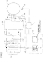
- Fig. 1 is a figure for explanation of a first embodiment of the ground fault sensing device of the present invention.
- a ground fault sensing device for a vehicle drive system in which an electric motor is driven by a battery via an inverter. It should be understood that ground fault sensing for the electric motor side (i.e. for the alternating current side) by this first embodiment will be explained.
- This drive system includes a main controller 1, a three-phase alternating current electric motor 10 (hereinafter termed the "electric motor"), an inverter 20, a battery 30 that serves as a direct current power supply, and a ground fault sensing device 40.
- the battery 30 is a battery group that provides a high voltage direct current power supply (the output voltage VB may, for example, be 340 V), and this battery is electrically insulated from the body of the vehicle (not shown in the figures).
- the battery 30 and the inverter 20 are connected by a positive side bus bar 61, which is a positive side direct current power supply line, and a negative side bus bar 62, which is a negative side direct current power supply line.
- the inverter 20 is an electrical power conversion device that converts direct current power into alternating current power. When direct current power is supplied from the battery 30 to the inverter 20, the inverter 20 converts this direct current power into alternating current power that is supplied to the electric motor 10.
- a capacitor 51 constitutes a smoothing circuit that suppresses fluctuations of the direct current voltage generated by the switching operation of the inverter 20).
- a line bypass capacitor (i.e. a Y-capacitor) 50 is provided to the positive and negative side bus bars 61 and 62 for eliminating noise superimposed upon the direct current power supply.
- the supply of alternating current power from the inverter 20 to the electric motor 10 is performed via cables for three phases: a U-phase cable 63, a V-phase cable 64, and a W-phase cable 65.
- the rotation speed of the electric motor 10 is detected by a rotation speed sensor 11, and the resulting detection signal is input to a main controller 1.
- the ground fault sensing device 40 is connected to the positive side bus bar 61. It should be understood that this ground fault sensing device 40 could also be connected to the negative side bus bar 62.
- the ground fault sensing device 40 includes a detection circuit 41 and a ground fault evaluation circuit 42.
- the detection circuit 41 is a circuit that extracts an envelope from an amplitude wave that is generated in the power supply line during a ground fault of the electric motor, and it is connected to the positive side bus bar 61 via a coupling capacitor 43.
- the direct current component in the positive side bus bar 61 is intercepted by this coupling capacitor 43.
- the ground fault evaluation circuit 42 monitors the voltage level of this envelope detected by the detection circuit 41, and determines that a ground fault has occurred on the electric motor side when this voltage level exceeds a threshold value.
- Fig. 2 is a figure for explanation of the situation when a ground fault has occurred on the alternating current side.
- a ground fault has occurred in the W-phase cable of the electric motor 10. Due to this ground fault, a ground fault resistance 70 is equivalently created between the W-phase cable and ground potential.
- the electric motor 10 may be considered as a source of voltage when it is rotating, since an inductive voltage is generated in the stator winding at this time. Because of this, if a ground fault has occurred on the alternating current side in which the load of the electric motor is imposed, then, due to the influence of this source of voltage, an amplitude wave, i.e. a voltage level fluctuation, is generated in the power supply line.
- this source of voltage consists of a two phase alternating current component generated by the other phases (i.e. the U-phase and the V-phase).
- the generated amplitude wave is input to the ground fault sensing device 40 along a path via the ground fault resistance 70, the grounded point of the Y-capacitor 50, and the coupling capacitor 43.
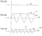
- Figs. 3A, 3B, and 3C are figures for explanation of amplitude waves generated during a ground fault of the electric motor; in these figures, the voltage level is shown along the vertical axis.
- Fig. 3A shows an example of the waveform when the electric motor 10 is not suffering any ground fault. Since no amplitude wave is generated in this case, the level V100 of the voltage on the side of the ground fault sensing device 40 that is connected via the coupling capacitor 43 is constant.
- the previously described amplitude wave is superimposed upon the voltage of the power supply line, so that an amplitude wave V101 or V102 is detected, as shown in Figs. 3B and 3C .
- the frequency of this amplitude wave V101 or V102 changes according to the characteristics of the electric motor 10 (its rotation speed, the number of its poles, and so on).
- Fig. 3B shows a case in which the rotation speed is low
- Fig. 3C shows a case in which the rotation speed is high.
- the value of its amplitude is smaller, the higher is the rotation speed N.
- the lines 111 and 112 are the respective envelopes of the amplitude waves V101 and V102.
- the voltage levels of these envelopes 111 and 112 are higher than the reference voltage level by ⁇ V1 and ⁇ V2.
- a plurality of threshold values may be stored as a table according to the rotation speed, and a threshold value may be selected according to the detected rotation speed and the table. If the ground fault decision is to be performed by the ground fault sensing device 40, then this table is stored within the ground fault sensing device 40; while, if the ground fault decision is to be performed by the main controller 1, then this table is stored within the main controller 1. Instead of such a table, it would also be acceptable to arrange to set the threshold value by substituting the rotation speed into a calculation equation.
- the detection circuit 41 is a circuit that extracts the envelope of the amplitude wave; in concrete terms, it has a structure as shown in Fig. 4 or Fig. 5 .
- a first example shown in Fig. 4 is a so-called envelope detection circuit that includes a time constant circuit in which a resistor R01 and a capacitor C01 are combined at a stage after diode wave detection (by a diode D01). It is possible to extract the envelope of the signal waveform by matching the time constant to the cycle of the signal that is to be detected.
- the amplitude wave that is input via the coupling capacitor 43 is rectified by the diode D01. And the high frequency component in the output is eliminated by the capacitor C01, while the low frequency component is smoothed by this capacitor C01.
- the time constant of the capacitor C01 and the resistor R01 is large, then the slope of the voltage drop of the discharge due to the capacitor C01 is less than the slope of the envelope of the amplitude wave, so that a normal output waveform is not obtained. Due to this, the time constant of the capacitor C01 and the resistor R01 is set appropriately by the detection circuit 41, so that the output waveform is close to the envelope of the input waveform. It is possible to keep the cost of the detection circuit 41 low, since the number of components is small and moreover the components themselves are cheap.
- the ground fault evaluation circuit 42 detects the voltage of the envelope obtained by the detection circuit 41. And ⁇ V1 or ⁇ V2 is obtained by taking the difference between this detected voltage and a reference voltage level. Thus, the ground fault evaluation circuit 42 makes its ground fault determination on the basis of ⁇ V1 or ⁇ V2: for example, it may determine that a ground fault is occurring if ⁇ V1 or ⁇ V2 is greater than a threshold value. In this case, the threshold value for the ground fault determination is set according to the rotation speed, since the fluctuation ⁇ V varies according to the rotation speed.
- the detection circuit 41 is built as a full wave rectification circuit that includes four diodes D02 through D05. It is arranged to perform full wave rectification upon the amplitude wave that is input with this diode bridge, and for the output thereof to be received by the parallel circuit of a resistor R02 and a capacitor C02.
- the detection circuit 41 by providing the detection circuit 41, it is arranged to extract the envelope of the amplitude wave generated due to a ground fault on the electric motor side, and to detect whether or not a ground fault has occurred on the electric motor side on the basis of fluctuation of the voltage level of this envelope. Due to this, it is possible simply and easily to detect the occurrence of a ground fault on the electric motor side. Moreover, while the voltage level of the envelope changes according to the rotation speed of the electric motor, it is possible to perform the ground fault determination even more reliably, since it is arranged to set the threshold value for this ground fault determination according to the rotation speed of the electric motor. Furthermore, the circuit that makes the decision as to the voltage level of the envelope can be built simply, and this implies a low cost of manufacture.
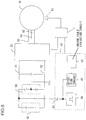
- Fig. 6 is a figure for explanation of a second embodiment of the ground fault sensing device of the present invention.
- This ground fault sensing device 40 includes a detection circuit 41, a ground fault evaluation circuit 42, a coupling capacitor 43, and a waveform output circuit 44. While in the first embodiment a ground fault sensing device was explained that detects the occurrence of a ground fault on the electric motor side, in this second embodiment, a structure is provided that is able to detect both the occurrence of a ground fault on the electric motor side (i.e. the alternating current side), and also the occurrence of a ground fault on the battery side (i.e. the direct current side). Due to this, this detection circuit includes both a circuit that handles the occurrence of a ground fault on the electric motor side, and also a circuit that handles the occurrence of a ground fault on the battery side.
- Fig. 7 is a figure showing an example of this detection circuit 41.
- a circuit 411 is a circuit that handles the occurrence of a ground fault on the electric motor side, and that extracts the envelope of the amplitude wave in a similar manner to the detection circuit 41 of the first embodiment. In concrete terms, it has a structure as shown in Fig. 4 or in Fig. 5 .
- a circuit 412 is a circuit that handles the occurrence of a ground fault on the battery side, and that includes a resistor R32, a capacitor C33, and a Zener diode D34.
- the combined structure of this circuit 412 and the waveform output circuit 44 constitutes a conventional ground fault sensing circuit of the alternating current voltage division type.
- the waveform output circuit 44 outputs a signal (hereinafter termed the "test signal") for ground fault testing, having a periodic waveform.
- the circuit 44 may output a square wave signal of duty ratio 50% and frequency 10Hz that has amplitude of 0 to 5 V.
- This test signal is superimposed upon the positive side bus bar 61, which is the subject circuit for evaluation.
- this test signal (alternating current signal) from the waveform output circuit 44 is applied via a detection resistor R31 and a coupling capacitor 43, and it is arranged to detect change of the insulation resistance from change of the amplitude of the response waveform at the point of connection A between the detection resistor R31 and the coupling capacitor 43.
- Fig. 8A is a figure showing an example of the test signal that is superimposed on the positive side bus bar 61 via the coupling capacitor 43.
- Figs. 8B and 8C are figures showing the response waveform at the point of connection A, when a square wave signal as shown in Fig. 8A is applied. It should be understood that the corruption of the waveform during its rise and its fall is due to delay and so on.
- the response waveform of Fig. 8B is one that represents the waveform during normal conditions, in which no ground fault is occurring on either the battery side or the electric motor side.
- the amplitude at this time is Vr1.
- the amplitude Vr2 of the response waveform shown in Fig. 8C becomes smaller than the amplitude Vr1 when no ground fault is occurring.
- the ground fault evaluation circuit 42 makes a decision as to whether or not a ground fault has occurred on the battery side by considering the change in the amplitude of this response waveform.
- an amplitude value that corresponds to the presence of a ground fault is set in advance as a threshold value, and it is determined that a ground fault has occurred on the direct current side if the value of the amplitude of the response waveform is smaller than this threshold value.
- Figs. 9A, 9B, 9C, and 9D are figures for explanation of the response waveforms when a ground fault has occurred on the electric motor side.
- Fig. 9A is a figure showing a detection signal (an output waveform) 200, and is the same as Fig. 8A .
- Fig. 9B is a figure showing the response waveform during normal conditions, and is the same as Fig. 8B .
- Fig. 9C is a figure showing the response waveform when a ground fault has occurred on the electric motor side. When a ground fault is occurring on the electric motor side, an amplitude wave of a frequency linked to the rotation speed of the electric motor 10 comes to be superimposed upon the waveform shown in Fig. 8B .
- Fig. 9D is a figure showing the waveform 201 when no ground fault is occurring, the waveform 202 in which an amplitude wave is superimposed upon the test signal, and the envelope 203, all mutually superimposed. If the voltage level of the waveform 201 when no ground fault is occurring is taken as being the reference level, then a fluctuation of ⁇ V with respect to this reference level is generated in the voltage level of the envelope 203 that is obtained from the amplitude wave. If this voltage level fluctuation ⁇ V is greater than the threshold value, then it is determined that a ground fault is occurring.
- Fig. 10 is a flow chart showing an example of ground fault sensing operation by the ground fault sensing device shown in Figs. 7 and 8 . While here this control is explained as being performed by the main control device, it would also be acceptable for it to be performed by the ground fault evaluation circuit 42.
- the processing shown in this flow chart starts when, for example, the main switch of the vehicle is turned to ON.
- a decision is made as to whether or not the electric motor 10 is in the stopped state or the operating state. In other words, if the rotation speed N of the electric motor is equal to zero, then it is decided that the motor is in the stopped state, and the flow of control proceeds to a step S110. On the other hand, if the rotation speed N is greater than zero, then it is decided that the motor is in the operating state, and the flow of control is transferred to a step S130.
- step S110 If the flow of control has reached the step S110, then no envelope can be obtained since the electric motor 10 is not rotating, even if, hypothetically, it is supposed that a ground fault has occurred on the electric motor side, since no amplitude wave is being generated. Accordingly it is necessary to prohibit the function of ground fault sensing by envelope detection, so a command is issued for prohibition of the envelope detection function. And in the next step S120 a command is issued to perform the direct current line ground fault sensing function. In other words, ground fault sensing upon the battery side is performed using the circuit 412 of Fig. 9 . That is, the amplitude value of the response waveform (Vr1 or Vr2 in Fig. 8 ) measured by the ground fault evaluation circuit 42 and the threshold value for ground fault decision are compared together.
- the threshold value for ground fault decision is a value that is obtained by converting the insulation resistance value into a voltage level.
- step S140 If in the step S140 it has been decided that a ground fault is occurring and the flow of control has proceeded to the step S150, then the drive system of the vehicle is stopped, and this sequence for ground fault sensing operation terminates. On the other hand, if it has been decided that no ground fault is occurring and the flow of control has been transferred to the step S160, then the operation of the drive system of the vehicle is continued, and the flow of control returns to the step S100.
- step S100 if in the step S100 it is decided that the rotation speed N of the electric motor 10 is greater than zero and the flow of control has been transferred to the step S130, then, in this step S130, ground fault sensing operation is performed using the detection circuit 412 that performs ground fault detection for the electric motor side.
- the ground fault evaluation circuit 42 measures the voltage level of the envelope obtained by the detection circuit 412, and compares together the fluctuation ⁇ V of the voltage level with respect to the reference level, and the threshold value. And, when the flow of control has been transferred from the step S130 to the step S140, then a decision is made from the result of the comparison in the step S130 as to whether or not a ground fault is occurring on the electric motor side. If it is decided that a ground fault is occurring, then the flow of control proceeds to the step S150, whereas if it is decided that no ground fault is occurring, then the flow of control is transferred to the step S160.
- the circuit 412 that obtains the envelope of the amplitude wave generated due to the occurrence of a ground fault on the electric motor side (i.e. on the alternating current side). And it is arranged reliably to perform ground fault detection upon the battery side without being influenced by the amplitude wave, by detecting the occurrence of a ground fault on the battery side in the state in which the electric motor 10 is not rotating.
- ground fault detection upon the electric motor side is performed in the state in which the electric motor 10 is rotating. And, if it is confirmed that the electric motor side is not suffering from the occurrence of a ground fault, then it may be considered that the reliability of the ground fault testing for the direct current side by the circuit 411 was sufficiently high. In other words, according to the structure of this second embodiment, it is possible reliably to detect the occurrence of a ground fault both upon the battery side and upon the electric motor side, so that enhancement of the safety may be anticipated.
Description
- The present invention relates to a ground fault sensing device. A ground fault sensing device as described in the preamble portion of
patent claim 1 has been known fromJP H08 70503 A - Since, in an electric vehicle or a hybrid electric vehicle, a high voltage battery is provided for operating devices such as an electric motor and an inverter, accordingly it is necessary to provide a ground fault sensing means for protecting the personnel riding in the vehicle from this high voltage. Due to this, technical standards have been determined for protecting the personnel riding in the vehicle from high voltage. For example, it has been made a requirement to install a device that monitors the insulation resistance between the active electrode and the electrical chassis, and that issues a warning to the driver when the value of this insulation resistance drops to 100 Ω per one volt of operating voltage.
- With a prior art ground fault sensing device, principally, what is detected is the occurrence of a ground fault on the direct current side of the high voltage battery (for example, refer to
US 2002 121902 A1 ). Thus, with the ground fault sensing method described inUS 2002 121902 A1 , a ground fault sensing signal is supplied to a direct current power supply circuit via a detection resistor and a coupling capacitor. And the amplitude of the voltage at a ground fault sensing point, which is the point of connection between the detection resistor and the coupling capacitor, is sampled at a sampling cycle that is 1/2 of the cycle of this periodic waveform (i.e. of the ground fault sensing signal), and determination of whether or not a ground fault is occurring is made by obtaining the difference between the voltage amplitude values detected during odd numbered sampling cycles and even numbered sampling cycles. - However since, with the method disclosed in
US 2002 121902 A1 , it is arranged to detect the occurrence of a ground fault on the battery side (i.e. the direct current side), accordingly it is difficult to detect the occurrence of a ground fault on the electric motor side (i.e. the alternating current side). Furthermore, sometimes it may happen that the ground fault determination described above becomes difficult if a ground fault has occurred upon the alternating current side, because an amplitude wave corresponding to the rotation speed of the electric motor is superimposed via the Y-capacitor upon the periodic waveform. -
JP H08 70503 A - The above-mentioned drawbacks are overcome with a ground fault sensing device having the features of
claim 1. Dependent claims are directed on features of preferred embodiments of the invention. - According to the present invention, it is possible to detect a ground fault on the alternating current side in a simple and easy manner.
-
-
Fig. 1 is a figure for explanation of a first embodiment of the ground fault sensing device of the present invention; -
Fig. 2 is a figure for explanation of the situation when a ground fault has occurred on the alternating current side; -
Figs. 3A, 3B, and 3C are figures for explanation of amplitude waves; -
Fig. 4 is a figure showing a first example of a detection circuit; -
Fig. 5 is a figure showing a second example of a detection circuit; -
Fig. 6 is a figure for explanation of a second embodiment of the ground fault sensing device of the present invention; -
Fig. 7 is a figure showing an example of a detection circuit in this second embodiment; -
Figs. 8A, 8B, and 8C are figures showing the waveform of a test signal and the response waveform, during ground fault testing on the battery side; -
Figs. 9A, 9B, 9C, and 9D are figures showing the waveform of a test signal, the response waveform, and the envelope, during ground fault testing on the electric motor side; -
Fig. 10 is a flow chart showing an example of ground fault sensing operation. - In the following, embodiments for implementation of the present invention will be explained with reference to the drawings.
-
Fig. 1 is a figure for explanation of a first embodiment of the ground fault sensing device of the present invention. Here, an example will be explained of a ground fault sensing device for a vehicle drive system in which an electric motor is driven by a battery via an inverter. It should be understood that ground fault sensing for the electric motor side (i.e. for the alternating current side) by this first embodiment will be explained. - This drive system includes a
main controller 1, a three-phase alternating current electric motor 10 (hereinafter termed the "electric motor"), aninverter 20, abattery 30 that serves as a direct current power supply, and a groundfault sensing device 40. Thebattery 30 is a battery group that provides a high voltage direct current power supply (the output voltage VB may, for example, be 340 V), and this battery is electrically insulated from the body of the vehicle (not shown in the figures). Thebattery 30 and theinverter 20 are connected by a positiveside bus bar 61, which is a positive side direct current power supply line, and a negativeside bus bar 62, which is a negative side direct current power supply line. Theinverter 20 is an electrical power conversion device that converts direct current power into alternating current power. When direct current power is supplied from thebattery 30 to theinverter 20, theinverter 20 converts this direct current power into alternating current power that is supplied to theelectric motor 10. - A
capacitor 51 constitutes a smoothing circuit that suppresses fluctuations of the direct current voltage generated by the switching operation of the inverter 20). Moreover, a line bypass capacitor (i.e. a Y-capacitor) 50 is provided to the positive and negativeside bus bars inverter 20 to theelectric motor 10 is performed via cables for three phases: aU-phase cable 63, a V-phase cable 64, and a W-phase cable 65. The rotation speed of theelectric motor 10 is detected by arotation speed sensor 11, and the resulting detection signal is input to amain controller 1. - The ground
fault sensing device 40 is connected to the positiveside bus bar 61. It should be understood that this groundfault sensing device 40 could also be connected to the negativeside bus bar 62. The groundfault sensing device 40 includes adetection circuit 41 and a groundfault evaluation circuit 42. Thedetection circuit 41 is a circuit that extracts an envelope from an amplitude wave that is generated in the power supply line during a ground fault of the electric motor, and it is connected to the positiveside bus bar 61 via acoupling capacitor 43. The direct current component in the positiveside bus bar 61 is intercepted by thiscoupling capacitor 43. And the groundfault evaluation circuit 42 monitors the voltage level of this envelope detected by thedetection circuit 41, and determines that a ground fault has occurred on the electric motor side when this voltage level exceeds a threshold value. -
Fig. 2 is a figure for explanation of the situation when a ground fault has occurred on the alternating current side. Here, a case is shown in which a ground fault has occurred in the W-phase cable of theelectric motor 10. Due to this ground fault, a ground fault resistance 70 is equivalently created between the W-phase cable and ground potential. Now, theelectric motor 10 may be considered as a source of voltage when it is rotating, since an inductive voltage is generated in the stator winding at this time. Because of this, if a ground fault has occurred on the alternating current side in which the load of the electric motor is imposed, then, due to the influence of this source of voltage, an amplitude wave, i.e. a voltage level fluctuation, is generated in the power supply line. - For example, when a ground fault has occurred in the W-phase of the electric motor 2 as shown in
Fig. 2 , then this source of voltage consists of a two phase alternating current component generated by the other phases (i.e. the U-phase and the V-phase). As shown by the arrow sign denoted by thesymbol 80 inFig. 2 , the generated amplitude wave is input to the groundfault sensing device 40 along a path via the ground fault resistance 70, the grounded point of the Y-capacitor 50, and thecoupling capacitor 43. -
Figs. 3A, 3B, and 3C are figures for explanation of amplitude waves generated during a ground fault of the electric motor; in these figures, the voltage level is shown along the vertical axis.Fig. 3A shows an example of the waveform when theelectric motor 10 is not suffering any ground fault. Since no amplitude wave is generated in this case, the level V100 of the voltage on the side of the groundfault sensing device 40 that is connected via thecoupling capacitor 43 is constant. On the other hand, when a ground fault is occurring in theelectric motor 10, the previously described amplitude wave is superimposed upon the voltage of the power supply line, so that an amplitude wave V101 or V102 is detected, as shown inFigs. 3B and 3C . - The frequency of this amplitude wave V101 or V102 changes according to the characteristics of the electric motor 10 (its rotation speed, the number of its poles, and so on). In concrete terms, the frequency of the amplitude wave is linked to a value calculated from the equation f=NP/120 (where N is the rotation speed and P is the number of poles).
Fig. 3B shows a case in which the rotation speed is low, whileFig. 3C shows a case in which the rotation speed is high. Moreover, along with the amplitude wave having a frequency that is linked to the rotation speed N, also the value of its amplitude is smaller, the higher is the rotation speed N. - In this embodiment, it is arranged to decide whether or not a ground fault is occurring by monitoring this type of fluctuation of the voltage level, in other words by monitoring fluctuation of the voltage level from the reference voltage level as shown by the
line 100 inFig. 3 . Thelines envelopes rotation speed sensor 11. - For example, a plurality of threshold values may be stored as a table according to the rotation speed, and a threshold value may be selected according to the detected rotation speed and the table. If the ground fault decision is to be performed by the ground
fault sensing device 40, then this table is stored within the groundfault sensing device 40; while, if the ground fault decision is to be performed by themain controller 1, then this table is stored within themain controller 1. Instead of such a table, it would also be acceptable to arrange to set the threshold value by substituting the rotation speed into a calculation equation. - As previously described, the
detection circuit 41 is a circuit that extracts the envelope of the amplitude wave; in concrete terms, it has a structure as shown inFig. 4 or Fig. 5 . A first example shown inFig. 4 is a so-called envelope detection circuit that includes a time constant circuit in which a resistor R01 and a capacitor C01 are combined at a stage after diode wave detection (by a diode D01). It is possible to extract the envelope of the signal waveform by matching the time constant to the cycle of the signal that is to be detected. The amplitude wave that is input via thecoupling capacitor 43 is rectified by the diode D01. And the high frequency component in the output is eliminated by the capacitor C01, while the low frequency component is smoothed by this capacitor C01. - It should be understood that, if the time constant of the capacitor C01 and the resistor R01 is large, then the slope of the voltage drop of the discharge due to the capacitor C01 is less than the slope of the envelope of the amplitude wave, so that a normal output waveform is not obtained. Due to this, the time constant of the capacitor C01 and the resistor R01 is set appropriately by the
detection circuit 41, so that the output waveform is close to the envelope of the input waveform. It is possible to keep the cost of thedetection circuit 41 low, since the number of components is small and moreover the components themselves are cheap. - The ground
fault evaluation circuit 42 detects the voltage of the envelope obtained by thedetection circuit 41. And ΔV1 or ΔV2 is obtained by taking the difference between this detected voltage and a reference voltage level. Thus, the groundfault evaluation circuit 42 makes its ground fault determination on the basis of ΔV1 or ΔV2: for example, it may determine that a ground fault is occurring if ΔV1 or ΔV2 is greater than a threshold value. In this case, the threshold value for the ground fault determination is set according to the rotation speed, since the fluctuation ΔV varies according to the rotation speed. - In a second example shown in
Fig. 5 , thedetection circuit 41 is built as a full wave rectification circuit that includes four diodes D02 through D05. It is arranged to perform full wave rectification upon the amplitude wave that is input with this diode bridge, and for the output thereof to be received by the parallel circuit of a resistor R02 and a capacitor C02. - In this way, in this first embodiment, by providing the
detection circuit 41, it is arranged to extract the envelope of the amplitude wave generated due to a ground fault on the electric motor side, and to detect whether or not a ground fault has occurred on the electric motor side on the basis of fluctuation of the voltage level of this envelope. Due to this, it is possible simply and easily to detect the occurrence of a ground fault on the electric motor side. Moreover, while the voltage level of the envelope changes according to the rotation speed of the electric motor, it is possible to perform the ground fault determination even more reliably, since it is arranged to set the threshold value for this ground fault determination according to the rotation speed of the electric motor. Furthermore, the circuit that makes the decision as to the voltage level of the envelope can be built simply, and this implies a low cost of manufacture. -
Fig. 6 is a figure for explanation of a second embodiment of the ground fault sensing device of the present invention. This groundfault sensing device 40 includes adetection circuit 41, a groundfault evaluation circuit 42, acoupling capacitor 43, and awaveform output circuit 44. While in the first embodiment a ground fault sensing device was explained that detects the occurrence of a ground fault on the electric motor side, in this second embodiment, a structure is provided that is able to detect both the occurrence of a ground fault on the electric motor side (i.e. the alternating current side), and also the occurrence of a ground fault on the battery side (i.e. the direct current side). Due to this, this detection circuit includes both a circuit that handles the occurrence of a ground fault on the electric motor side, and also a circuit that handles the occurrence of a ground fault on the battery side. -
Fig. 7 is a figure showing an example of thisdetection circuit 41. Acircuit 411 is a circuit that handles the occurrence of a ground fault on the electric motor side, and that extracts the envelope of the amplitude wave in a similar manner to thedetection circuit 41 of the first embodiment. In concrete terms, it has a structure as shown inFig. 4 or inFig. 5 . On the other hand, acircuit 412 is a circuit that handles the occurrence of a ground fault on the battery side, and that includes a resistor R32, a capacitor C33, and a Zener diode D34. The combined structure of thiscircuit 412 and thewaveform output circuit 44 constitutes a conventional ground fault sensing circuit of the alternating current voltage division type. - The
waveform output circuit 44 outputs a signal (hereinafter termed the "test signal") for ground fault testing, having a periodic waveform. For example, as this test signal, thecircuit 44 may output a square wave signal ofduty ratio 50% and frequency 10Hz that has amplitude of 0 to 5 V. This test signal is superimposed upon the positiveside bus bar 61, which is the subject circuit for evaluation. - In ground fault sensing of the alternating current voltage division type, this test signal (alternating current signal) from the
waveform output circuit 44 is applied via a detection resistor R31 and acoupling capacitor 43, and it is arranged to detect change of the insulation resistance from change of the amplitude of the response waveform at the point of connection A between the detection resistor R31 and thecoupling capacitor 43.Fig. 8A is a figure showing an example of the test signal that is superimposed on the positiveside bus bar 61 via thecoupling capacitor 43. AndFigs. 8B and 8C are figures showing the response waveform at the point of connection A, when a square wave signal as shown inFig. 8A is applied. It should be understood that the corruption of the waveform during its rise and its fall is due to delay and so on. - The response waveform of
Fig. 8B is one that represents the waveform during normal conditions, in which no ground fault is occurring on either the battery side or the electric motor side. The amplitude at this time is Vr1. On the other hand, since the ground fault resistance is added to the impedance on the vehicle side when a ground fault is occurring on the battery side, accordingly the amplitude Vr2 of the response waveform shown inFig. 8C becomes smaller than the amplitude Vr1 when no ground fault is occurring. The groundfault evaluation circuit 42 makes a decision as to whether or not a ground fault has occurred on the battery side by considering the change in the amplitude of this response waveform. Actually, an amplitude value that corresponds to the presence of a ground fault is set in advance as a threshold value, and it is determined that a ground fault has occurred on the direct current side if the value of the amplitude of the response waveform is smaller than this threshold value. -
Figs. 9A, 9B, 9C, and 9D are figures for explanation of the response waveforms when a ground fault has occurred on the electric motor side.Fig. 9A is a figure showing a detection signal (an output waveform) 200, and is the same asFig. 8A . AndFig. 9B is a figure showing the response waveform during normal conditions, and is the same asFig. 8B . Moreover,Fig. 9C is a figure showing the response waveform when a ground fault has occurred on the electric motor side. When a ground fault is occurring on the electric motor side, an amplitude wave of a frequency linked to the rotation speed of theelectric motor 10 comes to be superimposed upon the waveform shown inFig. 8B . - When the signal (the response wave) having the
waveform 202 as shown inFig. 9C is supplied to thecircuit 412 in which is a circuit that obtains the envelope of this amplitude wave, an envelope like that shown by thereference symbol 203 inFig. 9D is extracted.Fig. 9D is a figure showing thewaveform 201 when no ground fault is occurring, thewaveform 202 in which an amplitude wave is superimposed upon the test signal, and theenvelope 203, all mutually superimposed. If the voltage level of thewaveform 201 when no ground fault is occurring is taken as being the reference level, then a fluctuation of ΔV with respect to this reference level is generated in the voltage level of theenvelope 203 that is obtained from the amplitude wave. If this voltage level fluctuation ΔV is greater than the threshold value, then it is determined that a ground fault is occurring. -
Fig. 10 is a flow chart showing an example of ground fault sensing operation by the ground fault sensing device shown inFigs. 7 and8 . While here this control is explained as being performed by the main control device, it would also be acceptable for it to be performed by the groundfault evaluation circuit 42. The processing shown in this flow chart starts when, for example, the main switch of the vehicle is turned to ON. In a first step S100, a decision is made as to whether or not theelectric motor 10 is in the stopped state or the operating state. In other words, if the rotation speed N of the electric motor is equal to zero, then it is decided that the motor is in the stopped state, and the flow of control proceeds to a step S110. On the other hand, if the rotation speed N is greater than zero, then it is decided that the motor is in the operating state, and the flow of control is transferred to a step S130. - If the flow of control has reached the step S110, then no envelope can be obtained since the
electric motor 10 is not rotating, even if, hypothetically, it is supposed that a ground fault has occurred on the electric motor side, since no amplitude wave is being generated. Accordingly it is necessary to prohibit the function of ground fault sensing by envelope detection, so a command is issued for prohibition of the envelope detection function. And in the next step S120 a command is issued to perform the direct current line ground fault sensing function. In other words, ground fault sensing upon the battery side is performed using thecircuit 412 ofFig. 9 . That is, the amplitude value of the response waveform (Vr1 or Vr2 inFig. 8 ) measured by the groundfault evaluation circuit 42 and the threshold value for ground fault decision are compared together. The threshold value for ground fault decision is a value that is obtained by converting the insulation resistance value into a voltage level. - When the flow of control passes from the step S120 to the step S140, a decision is made as to whether or not a ground fault is occurring on the battery side. If the amplitude value is less than the threshold value, then it is decided that a ground fault has occurred, and the flow of control proceeds to a step S150. Conversely, if the amplitude value is greater than or equal to the threshold value, then it is decided that no ground fault has occurred, and the flow of control is transferred to a step S160.
- If in the step S140 it has been decided that a ground fault is occurring and the flow of control has proceeded to the step S150, then the drive system of the vehicle is stopped, and this sequence for ground fault sensing operation terminates. On the other hand, if it has been decided that no ground fault is occurring and the flow of control has been transferred to the step S160, then the operation of the drive system of the vehicle is continued, and the flow of control returns to the step S100.
- On the other hand, if in the step S100 it is decided that the rotation speed N of the
electric motor 10 is greater than zero and the flow of control has been transferred to the step S130, then, in this step S130, ground fault sensing operation is performed using thedetection circuit 412 that performs ground fault detection for the electric motor side. In other words, the groundfault evaluation circuit 42 measures the voltage level of the envelope obtained by thedetection circuit 412, and compares together the fluctuation ΔV of the voltage level with respect to the reference level, and the threshold value. And, when the flow of control has been transferred from the step S130 to the step S140, then a decision is made from the result of the comparison in the step S130 as to whether or not a ground fault is occurring on the electric motor side. If it is decided that a ground fault is occurring, then the flow of control proceeds to the step S150, whereas if it is decided that no ground fault is occurring, then the flow of control is transferred to the step S160. - As described above, in this second embodiment, in addition to a ground fault sensing device according to the prior art that detects the occurrence of a ground fault on the battery side (i.e. on the direct current side), there is also provided the
circuit 412 that obtains the envelope of the amplitude wave generated due to the occurrence of a ground fault on the electric motor side (i.e. on the alternating current side). And it is arranged reliably to perform ground fault detection upon the battery side without being influenced by the amplitude wave, by detecting the occurrence of a ground fault on the battery side in the state in which theelectric motor 10 is not rotating. If due to this detection it has been confirmed that no ground fault is occurring on the battery side, then ground fault detection upon the electric motor side is performed in the state in which theelectric motor 10 is rotating. And, if it is confirmed that the electric motor side is not suffering from the occurrence of a ground fault, then it may be considered that the reliability of the ground fault testing for the direct current side by thecircuit 411 was sufficiently high. In other words, according to the structure of this second embodiment, it is possible reliably to detect the occurrence of a ground fault both upon the battery side and upon the electric motor side, so that enhancement of the safety may be anticipated. - The embodiments described above may be employed individually, or in combination. This is because it is possible to obtain the advantageous effects of these various embodiments either singly, or in synergy. Moreover, the present invention is not to be considered as being limited by the details of the embodiments disclosed above, provided that its distinguishing features are maintained. For example, while in the embodiments described above a square wave pulse signal was applied as the test signal, it would also be possible to employ some other signal that changes cyclically, rather than a square wave signal.
- The above embodiments of the invention as well as the appended claims and figures show multiple characterizing features of the invention in specific combinations. The skilled person will easily be able to consider further combinations or sub-combinations of these features in order to adapt the invention as defined in the claims to his specific needs.
Claims (8)
- A ground fault sensing device (40) for a drive system that converts direct current electrical power from a direct current power supply (30) into alternating current electrical power and drives an electric motor (10) with that alternating current electrical power, comprising:an extraction circuit (41) that is connected to a power supply line (61) of the direct current power supply (30) via a coupling capacitor (43), that detects an amplitude wave (101, 102) that is generated when an alternating current side including the electric motor (10) is suffering a ground fault, and that extracts the envelope (111, 112) of the amplitude wave (101, 102); anda ground fault evaluation circuit (42) that makes a decision as to whether or not a ground fault has occurred on the alternating current side (63, 64, 65, 10) by comparing together the voltage level of the envelope (111, 112) measured by the extraction circuit (41) and a ground fault decision value,characterized in that the ground fault sensing device (40) further comprises a table adapted to store a plurality of threshold values according to the rotation speed of the electric motor (10), wherein the ground fault decision value is set as the threshold value of the table corresponding to the rotation speed of the electric motor (10) detected by a rotation speed sensor (11).
- A ground fault sensing device (40) according to Claim 1, wherein:
the ground fault evaluation circuit (42) compares the difference (ΔV1, ΔV2) between the voltage level of the envelope (111, 112) measured by the extraction circuit (41) and a reference voltage level set in advance with the ground fault decision value. - A ground fault sensing device (40) according to Claim 1 or 2, further comprising:a test signal output circuit (44) that applies a ground fault testing signal having a periodic waveform to the power supply line of the direct current power supply (30) via the coupling capacitor (43); anda direct current side ground fault sensing circuit (412) that detects the response waveform when the ground fault testing signal is applied, and that detects the occurrence of a ground fault on the direct current side including the direct current power supply (30), on the basis of change of the response waveform, wherein:
the extraction circuit (41) extracts the envelope of the amplitude wave superimposed upon the ground fault testing signal. - A ground fault sensing device (40) according to Claim 3, wherein:
the direct current side ground fault sensing circuit (412) determines that a ground fault has occurred on the direct current side, if the value of the amplitude of the response waveform having a periodic waveform is smaller than an amplitude value set in advance that corresponds to a ground fault. - A ground fault sensing device (40) according to Claim 3 or 4, further comprising:
a control means that performs control so that ground fault sensing for the direct current side is performed with the direct current side ground fault sensing circuit (412), when the electric motor (10) is stopped, and that performs control so that ground fault sensing for the alternating current side is performed by performing extraction with the extraction circuit (41), performing measurement with the extraction circuit (41), and performing ground fault evaluation with the ground fault evaluation circuit (42), when the electric motor (10) is operating. - A ground fault sensing device (40) according to Claim 5, wherein:
the control means outputs a command to stop the drive system, when a ground fault on at least one of the alternating current side and the direct current side is detected. - A ground fault sensing device according to one of the preceding claims, wherein:
the extraction circuit (41) is an envelope detection circuit. - A ground fault sensing device according to one of the preceding claims, wherein:
the extraction circuit (41) is a full wave rectification circuit.
Applications Claiming Priority (1)
| Application Number | Priority Date | Filing Date | Title |
|---|---|---|---|
| JP2009232283A JP5401250B2 (en) | 2009-10-06 | 2009-10-06 | Ground fault detection device |
Publications (2)
| Publication Number | Publication Date |
|---|---|
| EP2309280A1 EP2309280A1 (en) | 2011-04-13 |
| EP2309280B1 true EP2309280B1 (en) | 2019-04-10 |
Family
ID=43466632
Family Applications (1)
| Application Number | Title | Priority Date | Filing Date |
|---|---|---|---|
| EP10174047.0A Not-in-force EP2309280B1 (en) | 2009-10-06 | 2010-08-25 | Ground fault sensing device |
Country Status (4)
| Country | Link |
|---|---|
| US (1) | US8355226B2 (en) |
| EP (1) | EP2309280B1 (en) |
| JP (1) | JP5401250B2 (en) |
| CN (1) | CN102033186B (en) |
Families Citing this family (33)
| Publication number | Priority date | Publication date | Assignee | Title |
|---|---|---|---|---|
| US8133034B2 (en) * | 2004-04-09 | 2012-03-13 | Regal Beloit Epc Inc. | Controller for a motor and a method of controlling the motor |
| US8177520B2 (en) * | 2004-04-09 | 2012-05-15 | Regal Beloit Epc Inc. | Controller for a motor and a method of controlling the motor |
| EP2345124B1 (en) * | 2008-10-01 | 2018-12-19 | Regal Beloit America, Inc. | Controller for a motor and a method of controlling the motor |
| WO2012157036A1 (en) * | 2011-05-13 | 2012-11-22 | トヨタ自動車株式会社 | Vehicle power source system |
| JP5200175B1 (en) | 2012-02-29 | 2013-05-15 | パナソニック株式会社 | In-vehicle charger |
| US11329589B2 (en) * | 2012-03-28 | 2022-05-10 | Joy Global Underground Mining Llc | Ground fault detection methods on variable frequency drive systems |
| US9606163B2 (en) * | 2012-04-09 | 2017-03-28 | Toshiba Mitsubishi-Electric Industrial Systems Corporation | Ground fault detecting circuit and power converting device including the same |
| US9160161B2 (en) | 2012-05-04 | 2015-10-13 | Eaton Corporation | System and method for ground fault detection and protection in adjustable speed drives |
| CN102865909B (en) * | 2012-09-12 | 2014-07-16 | 安徽江淮汽车股份有限公司 | Detection circuit for motormeter |
| CN104049169B (en) * | 2013-03-15 | 2016-12-28 | 艾默生网络能源有限公司 | Ground detection device and method |
| US9093240B2 (en) | 2013-05-15 | 2015-07-28 | International Business Machines Corporation | Direct current ground fault interrupter |
| CN103399571B (en) * | 2013-07-31 | 2015-09-23 | 东方电气集团东风电机有限公司 | For pick-up unit and the method for electric vehicle motor controller high tension loop |
| CN103698703B (en) * | 2014-01-08 | 2016-03-23 | 中煤能源黑龙江煤化工有限公司 | Detector for armature fault of direct current motor |
| JP5788538B2 (en) * | 2014-01-08 | 2015-09-30 | ファナック株式会社 | Motor drive device with insulation deterioration detection function and motor insulation resistance detection method |
| DE102014207478A1 (en) * | 2014-04-17 | 2015-10-22 | Robert Bosch Gmbh | Method and device for determining an insulation resistance and high-voltage battery system with such a device |
| DE102014210290A1 (en) * | 2014-05-30 | 2015-12-03 | Bender Gmbh & Co. Kg | METHOD AND DEVICE FOR MONITORING A PROTECTIVE LADDER CONNECTION |
| CN104113263B (en) * | 2014-06-27 | 2017-02-15 | 联合汽车电子有限公司 | Electric drive system for new energy vehicle |
| DE102015218764A1 (en) * | 2014-12-30 | 2016-06-30 | Bender Gmbh & Co. Kg | Method and device for monitoring a protective conductor connection |
| US9599651B2 (en) * | 2015-02-19 | 2017-03-21 | Nec Energy Solutions, Inc. | Systems and methods of detecting ground faults in energy storage and/or generation systems that employ DC/AC power conversion systems |
| US10598715B2 (en) * | 2015-08-25 | 2020-03-24 | Eaton Intelligent Power Limited | System and method for automatic high resistance ground pulse activation and detection |
| US9859085B2 (en) | 2015-09-23 | 2018-01-02 | Hamilton Sundstrand Corporation | Fault protection devices and methods for power systems |
| DE102015223387A1 (en) * | 2015-11-26 | 2017-06-01 | Robert Bosch Gmbh | Method for detecting a state of a vehicle electrical system |
| CN105548798B (en) * | 2016-02-29 | 2018-12-07 | 珠海格力电器股份有限公司 | The ground detecting method and device of DC bus |
| CN110072737B (en) * | 2016-12-16 | 2022-06-10 | 日立安斯泰莫株式会社 | Vehicle-mounted control device |
| US11177647B2 (en) | 2017-07-18 | 2021-11-16 | Toshiba Mitsubishi-Electric Industrial Systems Corporation | Ground fault detector and power conditioner with input-side ground fault detection |
| CN108749579B (en) * | 2018-06-04 | 2020-07-24 | 北京新能源汽车股份有限公司 | Grounding self-inspection method and device for high-voltage system, high-voltage system and automobile |
| CN110967651B (en) * | 2018-09-30 | 2021-11-05 | 广东威灵汽车部件有限公司 | Electric automobile and short circuit to ground detection device thereof |
| WO2020170556A1 (en) * | 2019-02-19 | 2020-08-27 | 三洋電機株式会社 | Electrical fault detection device and vehicle power supply system |
| US20220011377A1 (en) * | 2019-02-19 | 2022-01-13 | Sanyo Electric Co., Ltd. | Electrical fault detection device and vehicle power supply system |
| EP3820031A1 (en) | 2019-11-05 | 2021-05-12 | Hamilton Sundstrand Corporation | Power device health monitoring utilising a bridge arrangement |
| CN112327207B (en) * | 2020-10-31 | 2022-09-16 | 贵州电网有限责任公司 | Portable direct current system ground fault judgment device and use method thereof |
| KR102395570B1 (en) * | 2020-11-25 | 2022-05-06 | 서울대학교 산학협력단 | Apparatus and method for determining fault of motor in variable driving environment |
| CN112526405B (en) * | 2020-12-03 | 2022-02-15 | 广东电网有限责任公司电力科学研究院 | Fault diagnosis method and related device for capacitor switching-out system |
Citations (2)
| Publication number | Priority date | Publication date | Assignee | Title |
|---|---|---|---|---|
| JPH0870503A (en) * | 1994-08-30 | 1996-03-12 | Nippondenso Co Ltd | Ground fault detector circuit for electric car |
| US20020121902A1 (en) * | 2001-01-11 | 2002-09-05 | Nissan Motor Co., Ltd. | Ground detection apparatus for electric vehicle |
Family Cites Families (16)
| Publication number | Priority date | Publication date | Assignee | Title |
|---|---|---|---|---|
| US4200897A (en) * | 1978-05-15 | 1980-04-29 | Dawley Robert E | Ground leakage current interrupter |
| US4868445A (en) * | 1988-06-20 | 1989-09-19 | Wand Saul N | Self tuned ultrasonic generator system having wide frequency range and high efficiency |
| JPH07128387A (en) * | 1993-10-29 | 1995-05-19 | Kawaju Bosai Kogyo Kk | Insulation monitor for line of isolated neutral wiring system |
| US5945802A (en) * | 1996-09-27 | 1999-08-31 | General Electric Company | Ground fault detection and protection method for a variable speed ac electric motor |
| JP2000013902A (en) * | 1998-06-26 | 2000-01-14 | Nissan Motor Co Ltd | Device for detecting ac side leak of electric vehicle |
| JP2003255012A (en) * | 2001-12-26 | 2003-09-10 | Toyota Motor Corp | Load driver, method for decoding impedance and computer-readable recording medium recording program for making computer execute impedance decision |
| JP3783633B2 (en) * | 2002-02-26 | 2006-06-07 | 日産自動車株式会社 | Ground fault detection device for vehicles |
| JP4098069B2 (en) * | 2002-12-04 | 2008-06-11 | 株式会社デンソー | Insulation failure detection circuit for motor circuit system |
| JP4133601B2 (en) * | 2003-06-06 | 2008-08-13 | 株式会社日本自動車部品総合研究所 | Motor drive device |
| JP4186887B2 (en) | 2004-07-07 | 2008-11-26 | 国産電機株式会社 | Earth leakage detector |
| CN101223681B (en) * | 2005-07-12 | 2012-05-16 | 株式会社小松制作所 | Leakage detector of vehicle-mounted power supply system and method |
| JPWO2007026603A1 (en) | 2005-08-29 | 2009-03-26 | トヨタ自動車株式会社 | Insulation resistance drop detector and self-abnormality diagnosis method for insulation resistance drop detector |
| JP5085206B2 (en) * | 2007-07-05 | 2012-11-28 | 株式会社東芝 | Variable magnetic flux drive system |
| WO2008016179A1 (en) | 2006-08-04 | 2008-02-07 | Toyota Jidosha Kabushiki Kaisha | Insulation resistance determining system, insulation resistance determining apparatus and insulation resistance determining method |
| JP2009017964A (en) * | 2007-07-10 | 2009-01-29 | Hoya Corp | Ultrasonic endoscope |
| JP5181579B2 (en) * | 2007-08-23 | 2013-04-10 | 日本精工株式会社 | Motor control device |
-
2009
- 2009-10-06 JP JP2009232283A patent/JP5401250B2/en not_active Expired - Fee Related
-
2010
- 2010-08-25 CN CN201010263197.XA patent/CN102033186B/en not_active Expired - Fee Related
- 2010-08-25 EP EP10174047.0A patent/EP2309280B1/en not_active Not-in-force
- 2010-08-25 US US12/868,260 patent/US8355226B2/en active Active
Patent Citations (2)
| Publication number | Priority date | Publication date | Assignee | Title |
|---|---|---|---|---|
| JPH0870503A (en) * | 1994-08-30 | 1996-03-12 | Nippondenso Co Ltd | Ground fault detector circuit for electric car |
| US20020121902A1 (en) * | 2001-01-11 | 2002-09-05 | Nissan Motor Co., Ltd. | Ground detection apparatus for electric vehicle |
Also Published As
| Publication number | Publication date |
|---|---|
| JP5401250B2 (en) | 2014-01-29 |
| US8355226B2 (en) | 2013-01-15 |
| CN102033186B (en) | 2014-06-25 |
| JP2011080823A (en) | 2011-04-21 |
| EP2309280A1 (en) | 2011-04-13 |
| US20110080676A1 (en) | 2011-04-07 |
| CN102033186A (en) | 2011-04-27 |
Similar Documents
| Publication | Publication Date | Title |
|---|---|---|
| EP2309280B1 (en) | Ground fault sensing device | |
| EP2905630B1 (en) | Fault detection in brushless exciters | |
| EP2856591B1 (en) | System and method for high resistance ground fault detection and protection in power distribution systems | |
| US7759888B2 (en) | AC motor controller | |
| US9625519B2 (en) | Drive failure protection | |
| US8649130B2 (en) | Motor driving apparatus having fault diagnostic function | |
| JP6831630B2 (en) | Alternator Rectifier Methods and Devices for Detecting Diode Short Circuit Failures | |
| US20080197855A1 (en) | Insulation Resistance Drop Detector and Failure Self-Diagnosis Method for Insulation Resistance Drop Detector | |
| EP2506408A2 (en) | Ground scheme identification method | |
| US20200287539A1 (en) | Phase loss detection device, compressor including the same, and phase loss detection method | |
| EP3029473A2 (en) | System and method for detecting ground fault in a dc system | |
| EP1818207A2 (en) | Electric rolling stock control apparatus | |
| EP1661233B1 (en) | Method and apparatus for detecting faults in ac to ac, or dc to ac power conversion equipments when the equipment is in a high impedance mode | |
| KR102466981B1 (en) | Apparatus and Method for detecting fault of switching device in inverter | |
| CN101009427A (en) | Power supply device | |
| US20090167314A1 (en) | Method and Device for Detecting Ground Faults in a Supply Cable | |
| EP2880457A1 (en) | Twelve-pulse autotransformer rectifier units | |
| US10703395B2 (en) | Method and device for monitoring an electric network in a rail vehicle and rail vehicle | |
| US20200052641A1 (en) | Method for detecting a motor phase fault of a motor arrangement and drive circuit for driving an electronically commutated motor | |
| JP2004361309A (en) | Motor drive unit | |
| GB2409905A (en) | Plausibility check of an electric three-phase system | |
| KR101531341B1 (en) | A detector for malfunction of 3-phase capacitor | |
| JPS6057295B2 (en) | Cycloconverter protection device |
Legal Events
| Date | Code | Title | Description |
|---|---|---|---|
| PUAI | Public reference made under article 153(3) epc to a published international application that has entered the european phase |
Free format text: ORIGINAL CODE: 0009012 |
|
| 17P | Request for examination filed |
Effective date: 20101216 |
|
| AK | Designated contracting states |
Kind code of ref document: A1 Designated state(s): AL AT BE BG CH CY CZ DE DK EE ES FI FR GB GR HR HU IE IS IT LI LT LU LV MC MK MT NL NO PL PT RO SE SI SK SM TR |
|
| AX | Request for extension of the european patent |
Extension state: BA ME RS |
|
| STAA | Information on the status of an ep patent application or granted ep patent |
Free format text: STATUS: EXAMINATION IS IN PROGRESS |
|
| 17Q | First examination report despatched |
Effective date: 20170606 |
|
| GRAP | Despatch of communication of intention to grant a patent |
Free format text: ORIGINAL CODE: EPIDOSNIGR1 |
|
| STAA | Information on the status of an ep patent application or granted ep patent |
Free format text: STATUS: GRANT OF PATENT IS INTENDED |
|
| RIC1 | Information provided on ipc code assigned before grant |
Ipc: B60L 3/00 20060101ALI20180920BHEP Ipc: G01R 31/02 20060101AFI20180920BHEP Ipc: G01R 31/00 20060101ALI20180920BHEP Ipc: B60L 3/12 20060101ALI20180920BHEP |
|
| INTG | Intention to grant announced |
Effective date: 20181019 |
|
| GRAS | Grant fee paid |
Free format text: ORIGINAL CODE: EPIDOSNIGR3 |
|
| GRAA | (expected) grant |
Free format text: ORIGINAL CODE: 0009210 |
|
| STAA | Information on the status of an ep patent application or granted ep patent |
Free format text: STATUS: THE PATENT HAS BEEN GRANTED |
|
| AK | Designated contracting states |
Kind code of ref document: B1 Designated state(s): AL AT BE BG CH CY CZ DE DK EE ES FI FR GB GR HR HU IE IS IT LI LT LU LV MC MK MT NL NO PL PT RO SE SI SK SM TR |
|
| REG | Reference to a national code |
Ref country code: GB Ref legal event code: FG4D |
|
| REG | Reference to a national code |
Ref country code: CH Ref legal event code: EP Ref country code: AT Ref legal event code: REF Ref document number: 1119443 Country of ref document: AT Kind code of ref document: T Effective date: 20190415 |
|
| REG | Reference to a national code |
Ref country code: IE Ref legal event code: FG4D |
|
| REG | Reference to a national code |
Ref country code: DE Ref legal event code: R096 Ref document number: 602010058117 Country of ref document: DE |
|
| REG | Reference to a national code |
Ref country code: NL Ref legal event code: MP Effective date: 20190410 |
|
| REG | Reference to a national code |
Ref country code: LT Ref legal event code: MG4D |
|
| REG | Reference to a national code |
Ref country code: AT Ref legal event code: MK05 Ref document number: 1119443 Country of ref document: AT Kind code of ref document: T Effective date: 20190410 |
|
| PG25 | Lapsed in a contracting state [announced via postgrant information from national office to epo] |
Ref country code: NL Free format text: LAPSE BECAUSE OF FAILURE TO SUBMIT A TRANSLATION OF THE DESCRIPTION OR TO PAY THE FEE WITHIN THE PRESCRIBED TIME-LIMIT Effective date: 20190410 |
|
| PG25 | Lapsed in a contracting state [announced via postgrant information from national office to epo] |
Ref country code: FI Free format text: LAPSE BECAUSE OF FAILURE TO SUBMIT A TRANSLATION OF THE DESCRIPTION OR TO PAY THE FEE WITHIN THE PRESCRIBED TIME-LIMIT Effective date: 20190410 Ref country code: LT Free format text: LAPSE BECAUSE OF FAILURE TO SUBMIT A TRANSLATION OF THE DESCRIPTION OR TO PAY THE FEE WITHIN THE PRESCRIBED TIME-LIMIT Effective date: 20190410 Ref country code: PT Free format text: LAPSE BECAUSE OF FAILURE TO SUBMIT A TRANSLATION OF THE DESCRIPTION OR TO PAY THE FEE WITHIN THE PRESCRIBED TIME-LIMIT Effective date: 20190910 Ref country code: NO Free format text: LAPSE BECAUSE OF FAILURE TO SUBMIT A TRANSLATION OF THE DESCRIPTION OR TO PAY THE FEE WITHIN THE PRESCRIBED TIME-LIMIT Effective date: 20190710 Ref country code: HR Free format text: LAPSE BECAUSE OF FAILURE TO SUBMIT A TRANSLATION OF THE DESCRIPTION OR TO PAY THE FEE WITHIN THE PRESCRIBED TIME-LIMIT Effective date: 20190410 Ref country code: SE Free format text: LAPSE BECAUSE OF FAILURE TO SUBMIT A TRANSLATION OF THE DESCRIPTION OR TO PAY THE FEE WITHIN THE PRESCRIBED TIME-LIMIT Effective date: 20190410 Ref country code: AL Free format text: LAPSE BECAUSE OF FAILURE TO SUBMIT A TRANSLATION OF THE DESCRIPTION OR TO PAY THE FEE WITHIN THE PRESCRIBED TIME-LIMIT Effective date: 20190410 Ref country code: ES Free format text: LAPSE BECAUSE OF FAILURE TO SUBMIT A TRANSLATION OF THE DESCRIPTION OR TO PAY THE FEE WITHIN THE PRESCRIBED TIME-LIMIT Effective date: 20190410 |
|
| REG | Reference to a national code |
Ref country code: DE Ref legal event code: R079 Ref document number: 602010058117 Country of ref document: DE Free format text: PREVIOUS MAIN CLASS: G01R0031020000 Ipc: G01R0031500000 |
|
| PG25 | Lapsed in a contracting state [announced via postgrant information from national office to epo] |
Ref country code: LV Free format text: LAPSE BECAUSE OF FAILURE TO SUBMIT A TRANSLATION OF THE DESCRIPTION OR TO PAY THE FEE WITHIN THE PRESCRIBED TIME-LIMIT Effective date: 20190410 Ref country code: BG Free format text: LAPSE BECAUSE OF FAILURE TO SUBMIT A TRANSLATION OF THE DESCRIPTION OR TO PAY THE FEE WITHIN THE PRESCRIBED TIME-LIMIT Effective date: 20190710 Ref country code: PL Free format text: LAPSE BECAUSE OF FAILURE TO SUBMIT A TRANSLATION OF THE DESCRIPTION OR TO PAY THE FEE WITHIN THE PRESCRIBED TIME-LIMIT Effective date: 20190410 Ref country code: GR Free format text: LAPSE BECAUSE OF FAILURE TO SUBMIT A TRANSLATION OF THE DESCRIPTION OR TO PAY THE FEE WITHIN THE PRESCRIBED TIME-LIMIT Effective date: 20190711 |
|
| PG25 | Lapsed in a contracting state [announced via postgrant information from national office to epo] |
Ref country code: IS Free format text: LAPSE BECAUSE OF FAILURE TO SUBMIT A TRANSLATION OF THE DESCRIPTION OR TO PAY THE FEE WITHIN THE PRESCRIBED TIME-LIMIT Effective date: 20190810 Ref country code: AT Free format text: LAPSE BECAUSE OF FAILURE TO SUBMIT A TRANSLATION OF THE DESCRIPTION OR TO PAY THE FEE WITHIN THE PRESCRIBED TIME-LIMIT Effective date: 20190410 |
|
| REG | Reference to a national code |
Ref country code: DE Ref legal event code: R097 Ref document number: 602010058117 Country of ref document: DE |
|
| PG25 | Lapsed in a contracting state [announced via postgrant information from national office to epo] |
Ref country code: RO Free format text: LAPSE BECAUSE OF FAILURE TO SUBMIT A TRANSLATION OF THE DESCRIPTION OR TO PAY THE FEE WITHIN THE PRESCRIBED TIME-LIMIT Effective date: 20190410 Ref country code: SK Free format text: LAPSE BECAUSE OF FAILURE TO SUBMIT A TRANSLATION OF THE DESCRIPTION OR TO PAY THE FEE WITHIN THE PRESCRIBED TIME-LIMIT Effective date: 20190410 Ref country code: DK Free format text: LAPSE BECAUSE OF FAILURE TO SUBMIT A TRANSLATION OF THE DESCRIPTION OR TO PAY THE FEE WITHIN THE PRESCRIBED TIME-LIMIT Effective date: 20190410 Ref country code: EE Free format text: LAPSE BECAUSE OF FAILURE TO SUBMIT A TRANSLATION OF THE DESCRIPTION OR TO PAY THE FEE WITHIN THE PRESCRIBED TIME-LIMIT Effective date: 20190410 Ref country code: CZ Free format text: LAPSE BECAUSE OF FAILURE TO SUBMIT A TRANSLATION OF THE DESCRIPTION OR TO PAY THE FEE WITHIN THE PRESCRIBED TIME-LIMIT Effective date: 20190410 |
|
| PLBE | No opposition filed within time limit |
Free format text: ORIGINAL CODE: 0009261 |
|
| STAA | Information on the status of an ep patent application or granted ep patent |
Free format text: STATUS: NO OPPOSITION FILED WITHIN TIME LIMIT |
|
| PG25 | Lapsed in a contracting state [announced via postgrant information from national office to epo] |
Ref country code: IT Free format text: LAPSE BECAUSE OF FAILURE TO SUBMIT A TRANSLATION OF THE DESCRIPTION OR TO PAY THE FEE WITHIN THE PRESCRIBED TIME-LIMIT Effective date: 20190410 Ref country code: SM Free format text: LAPSE BECAUSE OF FAILURE TO SUBMIT A TRANSLATION OF THE DESCRIPTION OR TO PAY THE FEE WITHIN THE PRESCRIBED TIME-LIMIT Effective date: 20190410 |
|
| 26N | No opposition filed |
Effective date: 20200113 |
|
| PG25 | Lapsed in a contracting state [announced via postgrant information from national office to epo] |
Ref country code: TR Free format text: LAPSE BECAUSE OF FAILURE TO SUBMIT A TRANSLATION OF THE DESCRIPTION OR TO PAY THE FEE WITHIN THE PRESCRIBED TIME-LIMIT Effective date: 20190410 |
|
| GBPC | Gb: european patent ceased through non-payment of renewal fee |
Effective date: 20190825 |
|
| PG25 | Lapsed in a contracting state [announced via postgrant information from national office to epo] |
Ref country code: LU Free format text: LAPSE BECAUSE OF NON-PAYMENT OF DUE FEES Effective date: 20190825 Ref country code: LI Free format text: LAPSE BECAUSE OF NON-PAYMENT OF DUE FEES Effective date: 20190831 Ref country code: SI Free format text: LAPSE BECAUSE OF FAILURE TO SUBMIT A TRANSLATION OF THE DESCRIPTION OR TO PAY THE FEE WITHIN THE PRESCRIBED TIME-LIMIT Effective date: 20190410 Ref country code: CH Free format text: LAPSE BECAUSE OF NON-PAYMENT OF DUE FEES Effective date: 20190831 Ref country code: MC Free format text: LAPSE BECAUSE OF FAILURE TO SUBMIT A TRANSLATION OF THE DESCRIPTION OR TO PAY THE FEE WITHIN THE PRESCRIBED TIME-LIMIT Effective date: 20190410 |
|
| REG | Reference to a national code |
Ref country code: BE Ref legal event code: MM Effective date: 20190831 |
|
| PG25 | Lapsed in a contracting state [announced via postgrant information from national office to epo] |
Ref country code: IE Free format text: LAPSE BECAUSE OF NON-PAYMENT OF DUE FEES Effective date: 20190825 |
|
| PG25 | Lapsed in a contracting state [announced via postgrant information from national office to epo] |
Ref country code: GB Free format text: LAPSE BECAUSE OF NON-PAYMENT OF DUE FEES Effective date: 20190825 Ref country code: BE Free format text: LAPSE BECAUSE OF NON-PAYMENT OF DUE FEES Effective date: 20190831 |
|
| PGFP | Annual fee paid to national office [announced via postgrant information from national office to epo] |
Ref country code: DE Payment date: 20200812 Year of fee payment: 11 Ref country code: FR Payment date: 20200715 Year of fee payment: 11 |
|
| REG | Reference to a national code |
Ref country code: DE Ref legal event code: R082 Ref document number: 602010058117 Country of ref document: DE Representative=s name: MANITZ FINSTERWALD PATENT- UND RECHTSANWALTSPA, DE Ref country code: DE Ref legal event code: R081 Ref document number: 602010058117 Country of ref document: DE Owner name: HITACHI ASTEMO, LTD., HITACHINAKA-SHI, JP Free format text: FORMER OWNER: HITACHI AUTOMOTIVE SYSTEMS, LTD., HITACHINAKA-SHI, IBARAKI, JP |
|
| PG25 | Lapsed in a contracting state [announced via postgrant information from national office to epo] |
Ref country code: CY Free format text: LAPSE BECAUSE OF FAILURE TO SUBMIT A TRANSLATION OF THE DESCRIPTION OR TO PAY THE FEE WITHIN THE PRESCRIBED TIME-LIMIT Effective date: 20190410 |
|
| PG25 | Lapsed in a contracting state [announced via postgrant information from national office to epo] |
Ref country code: MT Free format text: LAPSE BECAUSE OF FAILURE TO SUBMIT A TRANSLATION OF THE DESCRIPTION OR TO PAY THE FEE WITHIN THE PRESCRIBED TIME-LIMIT Effective date: 20190410 Ref country code: HU Free format text: LAPSE BECAUSE OF FAILURE TO SUBMIT A TRANSLATION OF THE DESCRIPTION OR TO PAY THE FEE WITHIN THE PRESCRIBED TIME-LIMIT; INVALID AB INITIO Effective date: 20100825 |
|
| REG | Reference to a national code |
Ref country code: DE Ref legal event code: R119 Ref document number: 602010058117 Country of ref document: DE |
|
| PG25 | Lapsed in a contracting state [announced via postgrant information from national office to epo] |
Ref country code: MK Free format text: LAPSE BECAUSE OF FAILURE TO SUBMIT A TRANSLATION OF THE DESCRIPTION OR TO PAY THE FEE WITHIN THE PRESCRIBED TIME-LIMIT Effective date: 20190410 |
|
| PG25 | Lapsed in a contracting state [announced via postgrant information from national office to epo] |
Ref country code: FR Free format text: LAPSE BECAUSE OF NON-PAYMENT OF DUE FEES Effective date: 20210831 Ref country code: DE Free format text: LAPSE BECAUSE OF NON-PAYMENT OF DUE FEES Effective date: 20220301 |