EP2309225A1 - Position measurement method, position measurement device, and program - Google Patents
Position measurement method, position measurement device, and program Download PDFInfo
- Publication number
- EP2309225A1 EP2309225A1 EP09773518A EP09773518A EP2309225A1 EP 2309225 A1 EP2309225 A1 EP 2309225A1 EP 09773518 A EP09773518 A EP 09773518A EP 09773518 A EP09773518 A EP 09773518A EP 2309225 A1 EP2309225 A1 EP 2309225A1
- Authority
- EP
- European Patent Office
- Prior art keywords
- exterior orientation
- characteristic points
- photographing
- image
- orientation parameters
- Prior art date
- Legal status (The legal status is an assumption and is not a legal conclusion. Google has not performed a legal analysis and makes no representation as to the accuracy of the status listed.)
- Withdrawn
Links
Images


Classifications
-
- G—PHYSICS
- G01—MEASURING; TESTING
- G01C—MEASURING DISTANCES, LEVELS OR BEARINGS; SURVEYING; NAVIGATION; GYROSCOPIC INSTRUMENTS; PHOTOGRAMMETRY OR VIDEOGRAMMETRY
- G01C11/00—Photogrammetry or videogrammetry, e.g. stereogrammetry; Photographic surveying
- G01C11/04—Interpretation of pictures
- G01C11/06—Interpretation of pictures by comparison of two or more pictures of the same area
- G01C11/08—Interpretation of pictures by comparison of two or more pictures of the same area the pictures not being supported in the same relative position as when they were taken
- G01C11/10—Interpretation of pictures by comparison of two or more pictures of the same area the pictures not being supported in the same relative position as when they were taken using computers to control the position of the pictures
-
- G—PHYSICS
- G01—MEASURING; TESTING
- G01C—MEASURING DISTANCES, LEVELS OR BEARINGS; SURVEYING; NAVIGATION; GYROSCOPIC INSTRUMENTS; PHOTOGRAMMETRY OR VIDEOGRAMMETRY
- G01C11/00—Photogrammetry or videogrammetry, e.g. stereogrammetry; Photographic surveying
- G01C11/04—Interpretation of pictures
- G01C11/06—Interpretation of pictures by comparison of two or more pictures of the same area
-
- G—PHYSICS
- G06—COMPUTING OR CALCULATING; COUNTING
- G06T—IMAGE DATA PROCESSING OR GENERATION, IN GENERAL
- G06T7/00—Image analysis
- G06T7/70—Determining position or orientation of objects or cameras
- G06T7/73—Determining position or orientation of objects or cameras using feature-based methods
- G06T7/74—Determining position or orientation of objects or cameras using feature-based methods involving reference images or patches
-
- G—PHYSICS
- G06—COMPUTING OR CALCULATING; COUNTING
- G06T—IMAGE DATA PROCESSING OR GENERATION, IN GENERAL
- G06T2207/00—Indexing scheme for image analysis or image enhancement
- G06T2207/10—Image acquisition modality
- G06T2207/10004—Still image; Photographic image
- G06T2207/10012—Stereo images
-
- G—PHYSICS
- G06—COMPUTING OR CALCULATING; COUNTING
- G06T—IMAGE DATA PROCESSING OR GENERATION, IN GENERAL
- G06T2207/00—Indexing scheme for image analysis or image enhancement
- G06T2207/30—Subject of image; Context of image processing
- G06T2207/30244—Camera pose
Definitions
- the present invention relates to a position measuring technique which measures photographing positions, photographing postures, and three-dimensional positions of objects based on moving images, and in particular, relates to a position measuring technique which reduces errors.
- the invention described in Japanese Unexamined Patent Application Publication No. 2007-171048 is directed to a method in which position of a camera is measured by a backward intersection method and position of an object is measured by a forward intersection method, when positions cannot be measured by a GPS (Global Positioning System). According to this aspect, the position measurement is not interrupted.
- GPS Global Positioning System
- the invention described in Japanese Unexamined Patent Application Publication No. 2006-250917 is directed to a method in which camera vector (CV) data showing the position of the camera and three-dimensional rotational position of the object based on video images, and position measured data of a moving object, are synchronized in time by reference time and are compared on the same time axis, and they are complementarily corrected.
- CV camera vector
- the present invention was completed in consideration of the above problems, and objects thereof are to provide a position measuring technique that measures photographing positions, photographing postures, and three-dimensional positions of objects based on moving images and which reduces errors.
- a position measurement method includes: an initial value calculating step for calculating initial values of exterior orientation parameters, which are a photographing position and a photographing posture, based on known points in an initial image or a photographing position and/or a photographing posture measured outside; an exterior orientation parameter-calculating step for calculating exterior orientation parameters, based on known points in a moving image which follows the initial image used in the initial value calculating step, or characteristic points in which three-dimensional coordinates are already calculated; an exterior orientation parameter correcting step for correcting the exterior orientation parameters calculated in the exterior orientation parameter-calculating step, based on a difference between photographing timing of the image and obtaining timing of the photographing position and/or the photographing posture measured outside; a bundle-adjusting step for simultaneously adjusting a bundle of the exterior orientation parameters of one or more images and the three-dimensional coordinates of the characteristic points, based on the exterior orientation parameters corrected in the exterior orientation parameter correcting step; a three-dimensional coordinate calculating step for calculating three-dimensional coordinates of characteristic
- the exterior orientation parameters are suitably corrected, even when the photographing timing of the image and the obtaining timing of the photographing position and/or the photographing posture measured outside are not synchronized, and therefore, the errors are decreased.
- the present invention according to Claim 2 is characterized in that in the invention according to Claim 1, the exterior orientation parameter correcting step corrects the exterior orientation parameters, based on the difference between the photographing timing of the image and the obtaining timing of the photographing position and/or the photographing posture measured outside, and based on accuracy of the photographing position and/or the photographing posture measured outside.
- the exterior orientation parameters calculated from the image are corrected in consideration of specific accuracy of the photographing position and/or the photographing posture measured outside.
- the present invention according to Claim 3 is characterized in that in the invention according to Claim 2, the accuracy of the photographing position measured outside is positioning accuracy of each positioning mode of a RTK-GPS (Real Time Kinematic Global Positioning System), and threshold value for correcting the exterior orientation parameters is changed based on the positioning mode.
- RTK-GPS Real Time Kinematic Global Positioning System
- the RTK-GPS changes the positioning mode in real time, based on position of a GPS satellite, multipath affected by surrounding conditions, correction information from a control station, and the like, which may affect the accuracy. Therefore, the exterior orientation parameters are suitably corrected by changing the threshold for correcting the exterior orientation parameters based on the positioning mode.
- the present invention according to Claim 4 is characterized in that in the invention according to Claim 2, the accuracy of the photographing posture measured outside is accuracy based on measuring time of the photographing posture.
- the photographing posture measured outside tends to accumulate error by measuring time in a measurement principle. Therefore, the exterior orientation parameters are suitably corrected by considering the accuracy based on the measuring time of the photographing posture.
- the present invention according to Claim 5 is characterized in that in the invention according to Claim 1, the bundle-adjusting step bundle-adjusts the photographing position and/or the photographing posture measured outside and the exterior orientation parameters and the three-dimensional coordinates of the characteristic points by calculating weights thereof and by weighting each data.
- the photographing position and/or the photographing posture measured outside is simultaneously bundle-adjusted also in addition to the exterior orientation parameters and the three-dimensional coordinates of the characteristic points.
- data having low accuracy are lightly processed and data having high accuracy are heavily processed, since the data are weighted to bundle-adjust.
- the errors of the exterior orientation parameters and the three-dimensional coordinates of the characteristic points are decreased.
- the present invention according to Claim 6 is characterized in that in the invention according to Claim 5, the weight of the photographing position and/or the photographing posture measured outside is calculated, based on the difference between the photographing timing of the image and the obtaining timing of the photographing position and/or the photographing posture measured outside.
- the errors of the exterior orientation parameters and the three-dimensional coordinates of the characteristic points are decreased, even when the photographing timing of the image and the obtaining timing of the photographing position and/or the photographing posture measured outside are not synchronized.
- the present invention according to Claim 7 is characterized in that in the invention according to Claim 5, the weights of the exterior orientation parameters and the three-dimensional coordinates of the characteristic points are calculated, based on residual between image coordinates of corresponding points calculated by tracking the characteristic points and image coordinates which project three-dimensional coordinates of the corresponding points on the image.
- the accuracy of the exterior orientation parameters and the three-dimensional coordinates of the characteristic points calculated from the images remarkably tends to depend on the tracking accuracy of the characteristic points.
- the residual according to Claim 7 represents the tracking accuracy. Therefore, the errors of the exterior orientation parameters and the three-dimensional coordinates of the characteristic points are decreased by changing the residual to the weights of the exterior orientation parameters and the three-dimensional coordinates of the characteristic points.
- the present invention according to Claim 8 is characterized in that in the invention according to Claim 5, the bundle-adjusting step is performed before calculation of the three-dimensional coordinates of the characteristic points subsequently detected or after calculation of the three-dimensional coordinates of the characteristic points subsequently detected.
- the bundle-adjusting step when the bundle-adjusting step is performed before the calculation of the three-dimensional coordinates of the characteristic points subsequently detected, the calculation accuracy of the three-dimensional coordinates of the characteristic points subsequently detected is improved.
- the bundle-adjusting step is performed after the calculation of the three-dimensional coordinates of the characteristic points subsequently detected, the three-dimensional coordinates of the characteristic points subsequently detected are calculated based on the corrected exterior orientation parameters, and as a result, a similar effect is obtained.
- the present invention according to Claim 9 is characterized in that the invention according to Claim 1 further includes a miscorresponding point removing step for removing miscorresponding points, based on residual between the image coordinates of the corresponding points calculated by tracking the characteristic points and the image coordinates which project the three-dimensional coordinates of the corresponding points on the image.
- the errors of the exterior orientation parameters and the characteristic points of the three-dimensional coordinates are reduced, since the miscorresponding points are removed even when the miscorresponding points are included in a tracked result of the characteristic points.
- the present invention according to Claim 10 is characterized in that the invention according to Claim 1 further includes a miscorresponding point removing step for projecting three-dimensional coordinates of corresponding points in prior and subsequent images on a stereo image and for removing miscorresponding points based on difference of coordinate values in a direction intersecting a baseline direction of prior and subsequent stereo images at right angle.
- the errors of the exterior orientation parameters and the characteristic points of the three-dimensional coordinates are reduced, since the miscorresponding points are removed even when the miscorresponding points are included in a tracked result of the characteristic points.
- the present invention according to Claim 11 is characterized in that in the invention according to Claim 9 or 10, the miscorresponding point removing step is performed after the bundle-adjusting step or before the exterior orientation parameter-calculating step.
- the miscorresponding point removing step when the miscorresponding point removing step is performed after the bundle-adjusting step, the calculation accuracy of the exterior orientation parameters of subsequent images is improved.
- the miscorresponding point removing step is performed before the exterior orientation parameter-calculating step, the errors of the exterior orientation parameters are decreased, since the exterior orientation parameters are not calculated based on the miscorresponding points.
- the present invention according to Claim 12 is characterized in that in the invention according to Claim 9 or 10, the miscorresponding point removing step according to Claim 9 or 10 is selected based on change in photographing conditions.
- the exterior orientation parameters and the three-dimensional coordinates of the characteristic points can be calculated without depending on the change of the photographing conditions.
- the present invention according to Claim 13 is characterized in that in the invention according to Claim 9 or 10, the miscorresponding point removing step estimates a threshold value by an LMedS estimation method.
- the LMedS estimation method can robustly estimate outliers, even when the data includes numerous outliers. Therefore, the errors of the exterior orientation parameters and the three-dimensional coordinates of the characteristic points are decreased.
- a position measurement program runs the following steps includes: an initial value calculating step for calculating initial values of exterior orientation parameters, which are a photographing position and a photographing posture, based on known points in an initial image or a photographing position and/or a photographing posture measured outside; an exterior orientation parameter-calculating step for calculating exterior orientation parameters, based on known points in a moving image which follows the initial image used in the initial value calculating step, or characteristic points in which three-dimensional coordinates are already calculated; an exterior orientation parameter correcting step for correcting the exterior orientation parameters calculated in the exterior orientation parameter-calculating step, based on difference between photographing timing of the image and obtaining timing of the photographing position and/or the photographing posture measured outside; a bundle-adjusting step for simultaneously adjusting a bundle of the exterior orientation parameters of one or more images and the three-dimensional coordinates of the characteristic points, based on the exterior orientation parameters corrected in the exterior orientation parameter correcting step; a three-dimensional coordinate calculating step for calculating three-dimensional coordinates
- the exterior orientation parameters are suitably corrected, even when the photographing timing of the image and the obtaining timing of the photographing position and/or the photographing posture measured outside are not synchronized, and therefore, the errors are decreased.
- a position measurement device includes: a moving image obtaining unit for obtaining a moving image that is photographed by relatively shifting a photographing section and a photographed object incrementally; a characteristic point detecting and tracking unit for sequentially inputting the images obtained by the moving image obtaining unit and for detecting and tracking characteristic points from the images; a position measuring unit for measuring photographing position of the moving image obtaining unit from the outside; a posture measuring unit for measuring photographing posture of the moving image obtaining unit from the outside; and a computer processing unit for inputting the moving image obtained by the moving image obtaining unit, the characteristic points detected and tracked by the characteristic point detecting and tracking unit, the photographing position measured by the position measuring unit, and the photographing posture measured by the posture measuring unit, and for calculating exterior orientation parameters, which are the photographing position and the photographing posture of the moving image, and three-dimensional coordinates of the characteristic points.
- the computer processing unit includes: an initial value calculating section for calculating initial values of the exterior orientation parameters, which are a photographing position and a photographing posture, based on known points in an initial image or the photographing position measured by the position measuring unit and the photographing posture measured by the posture measuring unit; an exterior orientation parameter calculating section for calculating exterior orientation parameters based on known points in a moving image which follows the initial image used in the initial value calculating section, or characteristic points in which three-dimensional coordinates are already calculated; an exterior orientation parameter correcting section for correcting the exterior orientation parameters calculated by the exterior orientation parameter calculating section, based on difference between photographing timing of the image and obtaining timing of the photographing position measured by the position measuring unit and/or the photographing posture measured by the posture measuring unit; a bundle adjusting section for simultaneously adjusting a bundle of the exterior orientation parameters of one or more images and the three-dimensional coordinates of the characteristic points, based on the exterior orientation parameters corrected by the exterior orientation parameter correcting section; and a three-dimensional coordinate calculating section for calculating three-dimensional coordinates
- the exterior orientation parameters are suitably corrected even when the photographing timing of the image and the obtaining timing of the photographing position and/or the photographing posture measured outside are not synchronized, and therefore, the errors are decreased.
- a position measurement method includes: an initial value calculating step for calculating initial values of exterior orientation parameters, which are a photographing position and a photographing posture, based on known points in an initial image or a photographing position and/or a photographing posture measured outside; an exterior orientation parameter-calculating step for calculating exterior orientation parameters, based on known points in a moving image which follows the initial image used in the initial value calculating step, or characteristic points in which three-dimensional coordinates are already calculated; an exterior orientation parameter evaluating step for evaluating the exterior orientation parameters calculated in the exterior orientation parameter-calculating step, based on at least one selected from the group consisting of track directions of the characteristic points, track distances of the characteristic points, a distribution rate of the characteristic points, an overlapping rate of the characteristic points, and a vertical parallax; a bundle-adjusting step for simultaneously adjusting a bundle of the exterior orientation parameters of one or more images and the three-dimensional coordinates of the characteristic points, based on the exterior orientation parameters corrected in the exterior orientation parameter
- change of photographing scenes or shift of photographing unit can be evaluated based on at least one selected from the group consisting of the track directions of the characteristic points, the track distances of the characteristic points, the distribution rate of the characteristic points, the overlapping rate of the characteristic points, and the vertical parallax.
- the change of photographing scenes and the shift of photographing unit make difficult to track the characteristic points, and decrease the accuracy of the exterior orientation parameters calculated from the images. Therefore, when the change of photographing scenes or the shift of photographing unit is relatively large, the exterior orientation parameters calculated from the images are evaluated to have low reliability, and in contrast, when the change of photographing scenes or the shift of photographing unit is relatively small, the exterior orientation parameters calculated from the images are evaluated to have high reliability.
- the photographing position and the photographing posture measured outside are used, and the exterior orientation parameters calculated from the images are not used. According to this aspect, the errors due to the change of photographing scenes and the shift of photographing unit can be decreased.
- the present invention according to Claim 17 is characterized in that in the invention according to Claim 16, the track directions of the characteristic points and the track distances of the characteristic points are calculated based on difference between tracks of corresponding points which correspond to the characteristic points in a prior image and tracks of the characteristic points subsequently detected in an image to be processed.
- the change of the photographing scenes and the shift of the photographing unit can be easily detected.
- the corresponding points which correspond to the characteristic points in the prior image and the characteristic points subsequently detected.
- the track direction and the track distance of the corresponding points are different from those of the subsequently detected characteristic points.
- the present invention according to Claim 18 is characterized in that in the invention according to Claim 16, the distribution rate of the characteristic points and the overlapping rate of the characteristic points are calculated by using total value of X coordinates and/or Y coordinates of the characteristic points when an origin is set at the center of the image.
- the change of photographing scenes or the shift of the photographing unit can be easily detected.
- the present invention according to Claim 19 is characterized in that in the invention according to Claim 16, the exterior orientation parameter evaluating step evaluates the exterior orientation parameters based on a value obtained by multiplying more than one value selected from the group consisting of the track directions of the characteristic points, the track distances of the characteristic points, the distribution rate of the characteristic points, the overlapping rate of the characteristic points, and the vertical parallax.
- the change of photographing scenes or the shift of the photographing unit can be detected by one parameter.
- the present invention according to Claim 20 is characterized in that in the invention according to Claim 16, the bundle-adjusting step bundle-adjusts the photographing position and/or the photographing posture measured outside and the exterior orientation parameters and the three-dimensional coordinates of the characteristic points by calculating weights thereof and by weighting each data.
- the photographing position and/or the photographing posture measured outside is simultaneously bundle-adjusted also in addition to the exterior orientation parameters and the three-dimensional coordinates of the characteristic points.
- data having low accuracy are lightly processed and data having high accuracy are heavily processed, since the data are weighted to bundle-adjust.
- the errors of the exterior orientation parameters and the three-dimensional coordinates of the characteristic points are decreased.
- the present invention according to Claim 21 is characterized in that in the invention according to Claim 20, the weight of the photographing position and/or the photographing posture measured outside is calculated based on difference between photographing timing of the image and obtaining timing of the photographing position and/or the photographing posture measured outside.
- the errors of the exterior orientation parameters and the three-dimensional coordinates of the characteristic points are decreased even when the photographing timing of the image and the obtaining timing of the photographing position and/or the photographing posture measured outside are not synchronized.
- the present invention according to Claim 22 is characterized in that in the invention according to Claim 20, the weights of the exterior orientation parameters and the three-dimensional coordinates of the characteristic points are calculated based on at least one selected from the group consisting of the track directions of the characteristic points, the track distances of the characteristic points, the distribution rate of the characteristic points, the overlapping rate of the characteristic points, and the vertical parallax.
- the errors of the exterior orientation parameters and the three-dimensional coordinates of the characteristic points are decreased.
- the present invention according to Claim 23 is characterized in that in the invention according to Claim 20, the bundle-adjusting step is performed before the calculation of the three-dimensional coordinates of the characteristic points subsequently detected or after the calculation of the three-dimensional coordinates of the characteristic points subsequently detected.
- the bundle-adjusting step when the bundle-adjusting step is performed before the three-dimensional coordinates of the characteristic points subsequently detected is calculated, the calculation accuracy of the three-dimensional coordinates of the characteristic points subsequently detected is improved.
- the bundle-adjusting step is performed after the three-dimensional coordinates of the characteristic points subsequently detected is calculated, the three-dimensional coordinates of the characteristic points subsequently detected is calculated based on the evaluated exterior orientation parameters, and as a result, a similar effect is obtained.
- the present invention according to Claim 24 is characterized in that the invention according to Claim 16 further includes a miscorresponding point removing step for removing miscorresponding points based on residual between image coordinates of corresponding points calculated by tracking the characteristic points and image coordinates which project three-dimensional coordinates of the corresponding points on the image.
- the errors of the exterior orientation parameters and the characteristic points of the three-dimensional coordinates are reduced, since the miscorresponding points are removed even when the miscorresponding points are included in a tracked result of the characteristic points.
- the present invention according to Claim 25 is characterized in that the invention according to Claim 16 further includes a miscorresponding point removing step for projecting three-dimensional coordinates of corresponding points in prior and subsequent images on a stereo image and for removing miscorresponding points based on difference of coordinate values in a direction intersecting a baseline direction of prior and subsequent stereo images at right angle.
- the errors of the exterior orientation parameters and the characteristic points of the three-dimensional coordinates are reduced, since the miscorresponding points are removed even when the miscorresponding points are included in a tracked result of the characteristic points.
- the present invention according to Claim 26 is characterized in that in the invention according to Claim 24 or 25, the miscorresponding point removing step is performed after the bundle-adjusting step or before the exterior orientation parameter-calculating step.
- the miscorresponding point removing step when the miscorresponding point removing step is performed after the bundle-adjusting step, the calculation accuracy of the exterior orientation parameters of subsequent images is improved.
- the miscorresponding point removing step is performed before the exterior orientation parameter-calculating step, the errors of the exterior orientation parameters are decreased, since the exterior orientation parameters are not calculated based on the miscorresponding points.
- the present invention according to Claim 27 is characterized in that in the invention according to Claim 24 or 25, the miscorresponding point removing step according to Claim 24 or 25 is selected based on change in photographing conditions.
- the exterior orientation parameters and the three-dimensional coordinates of the characteristic points can be calculated without depending on the change of the photographing conditions.
- the present invention according to Claim 28 is characterized in that in the invention according to Claim 24 or 25, the miscorresponding point removing step estimates threshold value by an LMedS estimation method.
- the LMedS estimation method can robustly estimate outliers even when the data includes numerous outliers. Therefore, the errors of the exterior orientation parameters and the three-dimensional coordinates of the characteristic points are decreased.
- the present invention according to Claim 29 is characterized in that a position measurement program runs the following steps including: an initial value calculating step for calculating initial values of exterior orientation parameters, which are a photographing position and a photographing posture, based on known points in an initial image or a photographing position and/or a photographing posture measured outside; an exterior orientation parameter-calculating step for calculating exterior orientation parameters based on known points in a moving image which follows the initial image used in the initial value calculating step, or characteristic points in which three-dimensional coordinates are already calculated; an exterior orientation parameter evaluating step for evaluating the exterior orientation parameters calculated in the exterior orientation parameter-calculating step based on at least one selected from the group consisting of track directions of the characteristic points, track distances of the characteristic points, a distribution rate of the characteristic points, an overlapping rate of the characteristic points, and a vertical parallax; a bundle-adjusting step for simultaneously adjusting a bundle of the exterior orientation parameters of one or more images and the three-dimensional coordinates of the characteristic points, based on the exterior orientation parameters corrected in the
- change of photographing scenes or shift of photographing unit can be evaluated, based on at least one selected from the group consisting of the track directions of the characteristic points, the track distances of the characteristic points, the distribution rate of the characteristic points, the overlapping rate of the characteristic points, and the vertical parallax. Therefore, the errors due to the change of photographing scenes or the shift of photographing unit can be decreased.
- a position measurement device includes a moving image obtaining unit for obtaining a moving image that is photographed by relatively shifting a photographing section and a photographed object incrementally; a characteristic point detecting and tracking unit for sequentially inputting images obtained by the moving image obtaining unit and for detecting and tracking the characteristic points from the images; a position measuring unit for measuring photographing position of the moving image obtaining unit from the outside; a posture measuring unit for measuring photographing posture of the moving image obtaining unit from the outside; and a computer processing unit for inputting the moving image obtained by the moving image obtaining unit, the characteristic points detected and tracked by the characteristic point detecting and tracking unit, the photographing position measured by the position measuring unit, and the photographing posture measured by the posture measuring unit, and for calculating exterior orientation parameters, which are the photographing position and the photographing posture of the moving image, and three-dimensional coordinates of the characteristic points.
- the computer processing unit includes an initial value calculating section for calculating initial values of the exterior orientation parameters, which are a photographing position and a photographing posture, based on known points in an initial image or the photographing position measured by the position measuring unit and the photographing posture measured by the posture measuring unit; an exterior orientation parameter calculating section for calculating exterior orientation parameters, based on known points in a moving image which follows the initial image used in the initial value calculating section, or characteristic points in which three-dimensional coordinates are already calculated; exterior orientation parameters evaluating section for evaluating the exterior orientation parameters calculated by the exterior orientation parameter calculating section, based on at least one selected from the group consisting of track directions of the characteristic points, track distances of the characteristic points, a distribution rate of the characteristic points, an overlapping rate of the characteristic points, and a vertical parallax; a bundle adjusting section for simultaneously adjusting a bundle of the exterior orientation parameters of one or more images and the three-dimensional coordinates of the characteristic points, based on the exterior orientation parameters corrected by the exterior orientation parameters evaluating section; and a three
- change of photographing scenes or shift of photographing unit can be evaluated, based on at least one selected from the group consisting of the track directions of the characteristic points, the track distances of the characteristic points, the distribution rate of the characteristic points, the overlapping rate of the characteristic points, and the vertical parallax. Therefore, the errors due to the change of photographing scenes or the shift of photographing unit can be decreased.
- the errors can be reduced.
- 1 denotes a position measurement device
- 2 denotes a moving image obtaining unit
- 3 denotes a characteristic point detecting and tracking unit
- 4 denotes a position measuring unit
- 5 denotes a posture measuring unit
- 6 denotes a reference clock
- 7 denotes a computer processing unit
- 8 denotes a characteristic point detecting section
- 9 denotes a characteristic point tracking section
- 10 denotes a controlling and calculating unit
- 11 denotes a memory unit
- 12 denotes an initial value calculating section
- 13 denotes an exterior orientation parameter calculating section
- 14 denotes an exterior orientation parameter correcting section
- 15 denotes a bundle adjusting section
- 16 denotes a three-dimensional coordinate calculating section
- 17 denotes a miscorresponding point removing section
- 18 denotes a detail measuring section
- 19 denotes an exterior orientation parameter and three-dimensional coordinate outputting section
- 20 denotes an image analyzing section
- 21 denotes an
- FIG. 1 is an overview of a position measurement device
- Fig. 2 is a functional block diagram of a position measurement device.
- a position measurement device 1 includes a moving image obtaining unit 2, a characteristic point detecting and tracking unit 3, a position measuring unit 4, a posture measuring unit 5, a reference clock 6, and a computer processing unit 7.
- the moving image obtaining unit 2 includes a camera for taking moving images, such as a video camera, a CCD camera (Charge Coupled Device Camera) for industrial measurement, and a CMOS camera (Complementary Metal Oxide Semiconductor Camera).
- the moving image obtaining unit 2 may include a camera for taking still images. In this case, an object is photographed while the object and the camera are relatively shifted incrementally, and plural still images are obtained.
- the characteristic point detecting and tracking unit 3 is made of a characteristic point detecting section 8 and a characteristic point tracking section 9.
- the characteristic point detecting section 8 detects characteristic points from a moving image obtained by the moving image obtaining unit 2.
- the characteristic point tracking section 9 tracks corresponding points, which correspond to the characteristic points detected by the characteristic point detecting section 8, in another image.
- the characteristic point detecting section 8 and the characteristic point tracking section 9 are mounted in the form of firmware such as ASIC (Application Specific Integrated Circuit) and FPGA (Field Programmable Gate Array).
- the characteristic point detecting section 8 and the characteristic point tracking section 9 may be made of software which is executed on a general-purpose computer.
- the position measuring unit 4 is made of a GPS (Global Positioning System) receiver, an IMU (Inertial Measurement Unit), and the like.
- the position measuring unit 4 is used for measuring a position of a camera (projection center). By combining the GPS and the IMU based on photographing conditions, exterior orientation parameters calculated from an image are appropriately corrected. The offset between the mounting position of the position measuring unit 4 and the mounting position of the camera is preliminarily set.
- the posture measuring unit 5 is made of a posture sensor such as a gyroscope, an IMU, an acceleration meter, an angular rate meter, an angular accelerometer, and combinations thereof. By combining these measuring parts based on photographing conditions, the exterior orientation parameters calculated from an image are appropriately corrected.
- the posture measuring unit 5 is used for measuring posture of the camera.
- the reference clock 6 is made of a crystal oscillator, a rubidium oscillator, a radio-controlled clock, or the like.
- the reference clock 6 converts the time of the moving image obtaining unit 2, the time of the position measuring unit 4, and the time of the posture measuring unit 5, to have the same time axis.
- the computer processing unit 7 is made of a PC (Personal Computer).
- the computer processing unit 7 includes a controlling and calculating unit 10 and a memory unit 11.
- the controlling and calculating unit 10 is made of a CPU (Central Processing Unit), and the memory unit 11 is made of a semiconductor memory device such as a RAM (Random Access Memory) and a ROM (Read Only Memory), a magnetic-storage device, or the like.
- the memory unit 11 stores operating systems and position measurement programs, and the controlling and calculating unit 10 reads and executes the programs.
- the position measurement program is made of an initial value calculating section 12, an exterior orientation parameter calculating section 13, an exterior orientation parameter correcting section 14, a bundle adjusting section 15, a three-dimensional coordinate calculating section 16, a miscorresponding point removing section 17, a detail measuring section 18, and an exterior orientation parameter and three-dimensional coordinate outputting section 19.
- the position measurement program can be provided by recording media such as a CD-ROM.
- the initial value calculating section 12 calculates initial values of interior orientation parameters of the camera (focal point distance, principal point position (misalignment of center of optical axis), lens distortion coefficient) and exterior orientation parameters (position and posture of the camera). This calculation is based on three-dimensional coordinates of a reference point measured by a total station or a GPS, and is also based on image coordinates of the reference point in an image in which the reference point is photographed.
- the exterior orientation parameter calculating section 13 calculates exterior orientation parameters based on a backward intersection method or a relative orientation method.
- a backward intersection method directions from an unknown point to at least three known points are observed, and the position of the unknown point is fixed as an intersection point of these directional lines.
- a single photo orientation or a DLT method may be used as the backward intersection method.
- the exterior orientation parameter correcting section 14 corrects the exterior orientation parameters calculated from the image, according to the difference of the photographing timing of the image and the obtaining timing of the positional data and the postural data.
- the positional data is obtained by the position measuring unit 4 and the postural data is obtained by the posture measuring unit 5.
- the bundle adjusting section 15 adjusts the corrected exterior orientation parameters and the three-dimensional coordinates of the characteristic points in one or more images, or all images, at the same time.
- the three-dimensional coordinate calculating section 16 calculates three-dimensional coordinates of subsequently detected characteristic points based on a forward intersection method.
- a forward intersection method directions from at least two known points to an unknown point are observed, and the position of the unknown point is fixed as an intersection point of these directional lines.
- the bundle adjustment is performed before or after the calculation of the three-dimensional coordinates of the subsequently detected characteristic points.
- the miscorresponding point removing section 17 removes points having relatively large error among tracked corresponding points by a backward projection or by using vertical parallaxes calculated from a relative orientation.
- error points are removed according to residual values of image coordinates, which are calculated from the three-dimensional coordinates of the characteristic points based on the backward intersection method, and image coordinates of the tracked corresponding points.
- exterior orientation parameters are calculated by using at least six corresponding points in right and left images.
- the vertical parallax is a difference of y-coordinates of corresponding points in two images that are stereographed, that is, a difference of coordinate values in a direction intersecting a baseline direction of the stereo images at a right angle.
- the stereo images are a pair of images and are made of two images photographed by cameras in a condition in which the optical axes are parallel, and directions intersecting a baseline direction at a right angle are parallel.
- the detail measuring section 18 executes three-dimensional modeling.
- the three-dimensional modeling is used for forming a three-dimensional object of a photographed object.
- the detail measuring section 18 calculates contours and surfaces from the three-dimensional coordinates of the characteristic points and thereby forming a wire-frame model and a surface model.
- the surface model has surfaces to which two-dimensional images are texture-mapped.
- the detail measuring section 18 performs texture analysis based on the mapped texture and calculates three-dimensional coordinates of characteristic portions of the texture.
- the three-dimensional coordinates of the characteristic portions of the texture are bundle adjusted and are corrected to be optimum value.
- the exterior orientation parameter and three-dimensional coordinate outputting section 19 outputs data of the exterior orientation parameters and data of the three-dimensional coordinates of the characteristic points or the characteristic portions of the texture.
- FIGs. 3 and 4 are flow charts showing operation of a position measurement device.
- the moving image obtaining unit 2 obtains moving images (step S1).
- the moving images are plural continuous images photographed by relatively shifting the moving image obtaining unit 2 and an object incrementally.
- the plural continuous images are sequentially input to the characteristic point detecting and tracking unit 3.
- the characteristic point detecting section 8 detects characteristic points in the image input to the characteristic point detecting and tracking unit 3 (step S2).
- a filter such as a Moravec filter, a Laplacian filter, and a Sobel filter
- the characteristic point tracking section 9 tracks corresponding points, which correspond to the characteristic points, in a subsequent image (step S3).
- template matching is used.
- a SSDA method Sequential Similarity Detection Algorithm
- a cross-correlation coefficient method may be used.
- the characteristic point detecting section 8 detects more characteristic points in an area in which the density of the characteristic points is decreased.
- the step S2 for detecting characteristic points and the step S3 for tracking the characteristic points are repeated in the continuous images.
- the information related to the characteristic points is embedded in each image.
- the image embedded with the information related to the characteristic points is sequentially output to the computer processing unit 7.
- the details of the processes of the step S2 and the step S3 are disclosed in Japanese Patent Application Laid-Open No. 2007-147457 and Japanese Patent Application Laid-Open No. 2007-183256 .
- initial values of interior orientation parameters and exterior orientation parameters of the camera are calculated from an image photographed with a reference point (step S4).
- an operator needs to set a reference point in an objective space and photograph the reference point.
- the operator needs to measure three-dimensional coordinates of the reference point in a real space by a total station or a GPS.
- the operator calculates initial values of interior orientation parameters and exterior orientation parameters of the camera by the backward intersection method based on the three-dimensional coordinates and the image coordinates of the reference point.
- the initial values of the exterior orientation parameters may be calculated from stereo images photographed at plural positions, by using the total station or the GPS for providing three-dimensional coordinate values of the plural positions instead of the three-dimensional coordinate values of the characteristic points.
- the operator may photograph plural images by moving a reference plate, in which plural reference points are drawn, without using the total station and the GPS.
- the distances between the reference points drawn in the reference plate are known values.
- image coordinates of the reference points are calculated from the plural images, which are photographed with the reference points, and the initial values of the position and the posture of the camera are obtained by using relative orientation. It should be noted that the coordinates are in a local coordinate system.
- exterior orientation parameters, and three-dimensional coordinates of the subsequently detected characteristic points are calculated in each of the images that were input (step S5).
- the backward intersection method or the relative orientation method is used.
- the forward intersection method is used. This process is performed on all of the images. The detail of this process will be described later.
- a detail measurement is performed (step S8).
- a formation of a wire-frame model, a formation of a surface model, a texture mapping, and a texture analysis are performed.
- a texture analysis three-dimensional coordinates of characteristic portions of a texture are calculated.
- the three-dimensional coordinates of the characteristic portions of the texture, and also the exterior orientation parameters and the three-dimensional coordinates of the characteristic points, which are calculated in the step S5, are bundle adjusted and are corrected to be optimum values.
- the data of the exterior orientation parameters and the three-dimensional coordinates are output (step S7).
- the process of calculating the three-dimensional coordinates and the exterior orientation parameters in the step S5 includes a step of calculation of exterior orientation parameters (step S10), a step of correction of the calculated exterior orientation parameters (step S11), a step of bundle adjustment of the corrected orientation parameters and the three-dimensional coordinates of known points and the characteristic points (step S12), and a step of calculation of three-dimensional coordinates of subsequently detected characteristic points (step S13).
- the bundle adjustment (step S12) may be performed before the calculation of the three-dimensional coordinates of the subsequently detected characteristic points ( Fig. 3 ) or after the calculation of the three-dimensional coordinates of the subsequently detected characteristic points ( Fig. 4 ).
- the calculation accuracy of the three-dimensional coordinates of the subsequently detected characteristic points is improved.
- the function is the same as the function in the case shown in Fig. 3 .
- step S10 Calculation of the exterior orientation parameters
- Fig. 5 is an explanatory diagram for explaining a backward intersection method.
- the backward intersection method directions from an unknown point O to at least three known points P 1 , P 2 , P 3 are observed, and the position of the unknown point O is fixed as the intersection point of these directional lines.
- Exterior orientation parameters (X 0 , Y 0 , Z 0 , ⁇ , f , ⁇ ) are calculated by the backward intersection method based on three-dimensional coordinates of reference points P 1 , P 2 , P 3 , which are set as initial values (or three-dimensional coordinates calculated in a prior frame).
- a single photo orientation and a DLT method are used as the backward intersection method and will be described hereinafter.
- a position O (X 0 , Y 0 , Z 0 ) and a posture ( ⁇ , f , ⁇ ) of a camera, which is used for taking a photograph, are calculated by using a collinearity condition formed on a reference point in the photograph.
- the collinearity condition is a condition in which a projection center, a photographic image, and objective points (Op 1 P 1 , O P2 P 2 , O P3 P 3 ) on the ground are on one straight line.
- the position O (X 0 , Y 0 , Z 0 ) of the camera and the posture ( ⁇ , f , ⁇ ) of the camera are exterior orientation parameters.
- the camera coordinate system is assumed to be (x, y, z)
- the photographic coordinate system is assumed to be (x, y)
- the ground coordinate system is assumed to be (X, Y, Z). It is assumed that photographs are taken by turning the camera to left by ⁇ , f , ⁇ with respect to the positive direction in each coordinate axis in series.
- three-dimensional coordinates of reference points corresponding to 4 image coordinates are substituted for a second degree perspective projection formula which is represented by a first formula.
- observation equations are made, and thereby parameters b1 to b8 are calculated.
- exterior orientation parameters are calculated from the following second formula.
- a 1 1 + tan 2 ⁇
- a 2 B 1 + B 2 ⁇ tan ⁇ / sin ⁇
- a 3 B 4 + B 5 ⁇ tan ⁇ / sin ⁇
- a 4 tan ⁇ / (cos ⁇ tan ⁇ )
- Zm Average elevation of four reference points (here, four reference points are coordinates on the same plane, so the elevation is assumed to be fixed.)
- the DLT method approximates a relationship between image coordinates and three-dimensional coordinates of an objective space by using a third degree perspective projection formula.
- the basic formula of the DLT method is the following third formula.
- the detail of the DLT method may be found in "Shunji Murai: Analytical Photogrammetry, pages 46 to 51 and pages 149 to 155".
- a linear formula of a fourth formula is derived.
- the fourth formula is converted into the following fifth formula.
- X Y Z 1 0 0 0 0 0 - xX - xY - xZ 0 0 0 0 X Y Z 1 - yX - yY - yZ ⁇ L 1 L 2 L 3 L 4 L 5 L 6 L 7 L 8 L 9 L 10 L 11 x y
- the L 1 to L 11 include the exterior orientation parameters.
- Fig. 6 is an explanatory diagram for explaining a relative orientation.
- exterior orientation parameters are calculated by using at least six corresponding points in right and left images.
- a coplanar condition such that two light rays connect projection centers O 1 , O 2 and a reference point P must be in the same plane, is used.
- the coplanar conditional formula is represented in the following sixth formula.
- X 01 Y 01 Z 01 1 X 02 Y 02 Z 02 1 X 1 Y 1 Z 1 1 X 2 Y 2 Z 2 1 0 X 01' Y 01' Z 01 : Coordinates of projected center of the left image X 02' Y 02' Z 02 : Coordinates of projected center of the right image X 1' , Y 1' Z 1 : Left image coordinates X 2' Y 2' Z 2 : Right image coordinates
- an origin point of a model coordinate system is assumed to be a projection center O 1 on the left image, and a line connecting to a projection center O 2 on the right image is assumed to be an X-axis.
- the length of the baseline is assumed to be a part length.
- five parameters are obtained: a rotary angle ⁇ 1 of the Z-axis and a rotary angle f 1 of the Y-axis of the left camera, a rotary angle ⁇ 2 the Z-axis, a rotary angle f 2 the Y-axis, and a rotary angle ⁇ 2 the X-axis of the right camera.
- X 2 Y 2 Z 2 1 0 0 0 cos ⁇ 2 - sin ⁇ 2 0 sin ⁇ 2 cos ⁇ 1 ⁇ cos ⁇ 2 0 sin ⁇ 2 0 1 0 - sin ⁇ 2 0 cos ⁇ 2 ⁇ cos ⁇ 2 - sin ⁇ 2 0 sin ⁇ 2 cos ⁇ 2 cos ⁇ 2 - sin ⁇ 2 0 sin ⁇ 2 cos ⁇ 2 0 0 0 1 ⁇ x 2 y 2 - c + 1 0 0 0
- the positional data of the position measuring unit 4 and the postural data of the posture measuring unit 5 include the difference between the photographing timing of the image and the obtaining timings of the positional data of the position measuring unit 4 or the postural data of the posture measuring unit 5.
- the exterior orientation parameters are corrected after this positional data of the position measuring unit 4 and this postural data of the posture measuring unit 5 are evaluated.
- the method for correcting the exterior orientation parameters will be described hereinafter.
- the positional data obtained from the position measuring unit 4 have specific accuracy according to each device. For example, when the accuracy is represented as ⁇ , 2 ⁇ , 3 ⁇ , or the like is used for evaluation values (threshold values) of the positional data of the GPS and the IMU.
- the positional data of the GPS and the IMU include the error based on the difference between the photographing timing of the image and the obtaining timing of the positional data of the GPS and the IMU. If the positional data of the GPS and the IMU are out of the range of the threshold value, the position of the camera calculated from the image is selected.
- the positional data of the GPS and the IMU are selected.
- the offset between the mounting position of the camera and the mounting position of the GPS or the IMU is preliminary corrected.
- the time of the GPS is not synchronized with the time of the camera. This is because synchronization of the time of the GPS and the time of the camera requires a large investment and therefore is practically difficult to realize. Therefore, in the present invention, the obtaining time of the positional data of the GPS and the photographing time of the image are converted to a reference time output from the reference clock 6. The converted time compensates transmission delay of the positional data and transmission delay of the image data.
- the frame rate of the moving image do not coincide with the obtaining rate of the positional data of the GPS, whereby the photographing timing of the image do not synchronize with the obtaining timing of the positional data of the GPS. Therefore, the error in the positional data of the GPS includes the error based on the difference between the photographing timing of the image and the obtaining timing of the positional data of the GPS.
- Fig. 7A is a timing chart in a case in which a photographing timing of an image is not synchronized with obtaining timing of positional data of a GPS
- Fig. 7B is a timing chart in a case in which a photographing timing of an image is synchronized with obtaining timing of positional data of a GPS.
- the value of ⁇ t in the tenth formula is usually unknown.
- the frame rate of the moving image is set to be 30 fps
- the obtaining rate of the positional data of the GPS is set to be 1 fps
- the value of ⁇ t is plus or minus 1/30 seconds at most as shown in Fig. 7B .
- the position measurement device may be structured to change the value of ⁇ t.
- the photographing time of the image and the obtaining time of the positional data of the GPS are represented by the same time axis according to the reference clock 6. Therefore, the time difference between the obtaining time of the positional data of the GPS and the photographing time of an image, which is photographed at a time nearest to the obtaining time, is represented as ⁇ t.
- the value of ⁇ t shown in Fig. 7A is obtained by calculating a difference of the photographing time of the image and the obtaining time of the positional data of the GPS.
- the rate v is calculated from a moving distance of the characteristic point in the moving image and the frame rate of the moving image.
- the following eleventh formula is a formula for computation of the rate v.
- v X i - X i - 1 ⁇ fps
- X i Position coordinate of the characteristic point in i frame
- X i -1 Position coordinate of the characteristic point in i -1 frame
- fps Frame rate (frame/sec)
- the positioning accuracy of the GPS varies depending on values of a satellite position (DOP: Dilution of Precision), multipath, link quality (LQ), convergence estimation of positioning calculation, and the like.
- DOP Dilution of Precision
- LQ link quality
- a positioning mode is changed in real time according to a position of a GPS satellite, effects of multipath affected by surrounding environment, correction information from a control station, and the like.
- Table 1 schematically shows positioning accuracy in each positioning mode.
- a total error ST ALL in the positional data of the GPS including the difference of the photographing timing of the image and the obtaining timing of the positional data of the GPS is represented by a twelfth formula.
- Et 0.1 m
- GPS rtke 0.03 m in the RTK-fix positioning mode
- ET ALL 0.13 m
- the exterior orientation parameters (position of the camera) calculated from the image is used instead of the positional data of the GPS.
- Et ALL Et + GPS rtke
- Whether the exterior orientation parameters (position of the camera) will be corrected or not may be selected depending on which positioning mode is used for measuring the positional data of the GPS, among the positioning mode shown in the Table 1. For example, only the RTK-fix positioning mode is selected to be used. In this case, the exterior orientation parameters calculated from the image are selected.
- the positional data of the GPS which includes the difference between the photographing timing of the image and the obtaining timing of the positional data of the GPS.
- Fig. 8A shows a case in which positional data of a GPS is in the range of a predetermined threshold value
- Fig. SB shows a case in which positional data of a GPS is out of the range of a predetermined threshold value.
- the positional data of the GPS includes a difference between a photographing timing of an image and obtaining timing of the positional data of the GPS.
- the positional data Et ALL of the GPS is in the range of the predetermined threshold value
- the positional data of the GPS is selected.
- the exterior orientation parameters position of the camera
- the postural data obtained from the posture measuring unit 5 is evaluated by using 2 ⁇ or 3 ⁇ of an assumable accuracy ⁇ as an evaluation value (threshold value).
- the postural data includes an error based on the difference between the photographing timing of the image and the obtaining timing of the postural data of the posture sensor and the IMU. That is, if this postural data is out of the range of the threshold value, the posture of the camera calculated from the image is selected. On the other hand, if this postural data is in the range of the threshold value, the postural data of the posture measuring unit 5 is selected.
- the postural data of the posture measuring unit 5 is made of three rotary angles ( ⁇ , ⁇ , ⁇ ) of camera coordinate axes, and one of the rotary angles may be evaluated, or two or all three of the rotary angles may be evaluated. In this case, whether the rotary angles are used or not is set depending on the accuracy of the posture sensor and the IMU.
- Fig. 9A shows a relationship between a measuring time of postural data of a posture sensor and an accumulated error.
- a measuring time from setting of an initial value or from resetting of the hardware is represented as t, and an accumulated error is approximated to an exponential function of 1.05 t -1.
- the time of the posture sensor is not synchronized with the time of the camera
- the obtaining time of the postural data and the photographing time of the image are converted to the reference time output from the reference clock 6.
- the converted time compensates the transmission delay of the postural data of the posture sensor and the transmission delay of the image data.
- the frame rate of the moving image does not coincide with the obtaining rate of the postural data of the posture sensor, whereby the photographing timing of the image does not synchronized with the obtaining timing of the postural data of the posture sensor. Therefore, the error in the postural data of the posture sensor includes the error based on the difference between the photographing timing of the image and the obtaining timing of the postural data of the posture sensor.
- Fig. 9B is a timing chart in a case in which a photographing timing of an image is not synchronized with obtaining timing of postural data of a posture sensor.
- Fig. 9B it is assumed that the difference of the photographing timing of the image and the obtaining timing of the postural data of the posture sensor is represented as ⁇ t, and the posture of the camera is changed at angle rates v x , v y , v z at that time.
- the errors Ext, Eyt, Ezt of the postural data of the posture sensor are represented by the following fourteenth formula.
- the photographing time of the image and the obtaining time of the postural data of the posture sensor are represented by the same time axis according to the reference clock 6. Therefore, time difference between the obtaining time of the postural data of the posture sensor and the photographing time of an image, which is photographed at a time nearest to the obtaining time, is represented as ⁇ t.
- the value of ⁇ t shown in Fig. 9B is obtained by calculating a difference of the photographing time of the image and the obtaining time of the postural data of the posture sensor.
- values obtained from the posture sensor and the IMU are used.
- a bundle adjustment is performed on the exterior orientation parameters and the three-dimensional coordinates of the characteristic points in one or more images, or all images at the same time.
- the bundle adjustment method uses a collinearity condition such that light fluxes (bundles) connecting a point in the objective space, a point in the image, and the projection center, must be on the same straight line.
- an observation equation is formed for each of the light flux in each image based on the collinearity condition, and simultaneous adjustment is performed by the least-squares method.
- the collinearity conditional formula is represented as the following sixteenth formula.
- the symbols ⁇ x and ⁇ y represent correction terms of the internal orientation parameters (focal point distance, principal point position, lens distortion coefficient).
- the following eighteenth formula represents a compensatory model of internal orientation parameters in a case in which a lens has distortion in a radiation direction.
- the internal orientation parameters are adjusted at the same time by using the eighteenth formula. That is, the bundle adjustment includes self calibration.
- three-dimensional coordinates of subsequently detected characteristic points are calculated. These characteristic points were detected in an area in which the density of the characteristic points was decreased.
- the forward intersection method or the DLT method may be used.
- the calculation of the three-dimensional coordinates in the step S13 may be performed before the bundle adjustment (step S12).
- Fig. 10 is an explanatory diagram for explaining a forward intersection method.
- the forward intersection method directions from at least two of known points (O 1 , O 2 ) to an unknown point P are observed, and the position of the unknown point P is fixed as an intersection point of these directional lines.
- a coordinate system of an objective space is assumed to be O-XYZ. Coordinates (X 01 , Y 01 , Z 01 ) of a projection center O 1 of a camera and tilts( ⁇ 1 , f 1 , ⁇ 1 ) of camera coordinate axes in a prior frame image, and coordinates (X 02 , Y 02 , Z 02 ) of a projection center O 2 the camera and tilts (posture) ( ⁇ 2 , f 2 , ⁇ 2 ) of camera coordinate axes in a current frame image, are known values. In addition, internal orientation parameters (focal point distance, principal point position, lens distortion coefficient) are also known valuers.
- an unknown point P (X, Y, Z) in the objective space is fixed as an intersection point of a light ray (O 1 p 1 ) and a light ray (O 2 p 2 ).
- the two light rays do not intersect because there are essentially errors, and therefore, the intersection position is obtained by the least-squares method.
- a collinearity conditional formula for the two light rays is formed, and the exterior orientation parameters, the internal orientation parameters, and the image coordinates of the corresponding point, all of which are known values, are substituted for the sixteenth formula.
- approximate values including correction amounts of the unknown point P are substituted for the collinearity conditional formula.
- the approximate values of the unknown point P are represented as (X', Y', Z')
- the approximate values including the correction amounts are represented as (X' + ⁇ X, Y' + ⁇ Y, Z' + ⁇ Z).
- the sixteenth formula is expanded by using Taylor's formula about the approximate value and is linearized.
- the correction amounts are calculated by the least-squares method.
- the approximate values are corrected according to the calculated correction amounts, and the above calculations are repeated in the same manner, whereby convergence results are obtained.
- the three-dimensional coordinates P (X, Y, Z) of the characteristic point is calculated.
- the difference between the photographing timing of the image and the obtaining timing of the positional data of the position measuring unit 4 or the postural data of the posture measuring unit 5, is used as an error of the positional data of the position measuring unit 4 or the postural data of the posture measuring unit 5.
- the positional data of the position measuring unit 4 and the postural data of the posture measuring unit 5 include this difference.
- the exterior orientation parameters are corrected depending on whether this positional data and this postural data are in the range of predetermined threshold values or not. Even when the photographing timing of the image do not synchronize with the obtaining timing of the positional data of the position measuring unit 4 and the postural data of the posture measuring unit 5, the exterior orientation parameters are appropriately corrected. Therefore, the errors are decreased.
- the positioning mode is changed in real time based on a position of a GPS satellite, multipath affected by surrounding environment, correction information from a control station, and the like, which may affect the accuracy. Accordingly, by changing the threshold value for correcting the exterior orientation parameters based on the positioning mode, the exterior orientation parameters are appropriately corrected.
- RTK-GPS Real Time Kinematic GPS
- the error tends to accumulate due to the function of the measurement and the measuring time t. Therefore, by including the accuracy based on the measuring time t of the postural data, the exterior orientation parameters are appropriately corrected.
- change of photographing scenes and shift of a photographing unit are evaluated based on at least one selected from the group consisting of directions and distances of tracks of the characteristic points, a distribution rate of the characteristic points, an overlapping rate, and a vertical parallax.
- Fig. 11 is a functional block diagram of a position measurement device.
- the position measurement program further includes an image analyzing section 20 compared to the position measurement program shown in Fig. 2 .
- the position measurement program includes an exterior orientation parameter evaluating section 21 instead of the exterior orientation parameter correcting section 14 in Fig. 2 .
- change of photographing scenes and shift of a photographing unit are analyzed based on track directions of the characteristic points, moved distances of the characteristic points, a distribution rate of the characteristic points, an overlapping rate, and a vertical parallax.
- the exterior orientation parameters calculated from the image are evaluated based on the analyzed result of the image analyzing section 20.
- the exterior orientation parameters are corrected by using the positional data obtained from the position measuring unit 4 and the postural data obtained from the posture measuring unit 5.
- the exterior orientation parameters calculated from the image is selected.
- FIGs. 12 and 13 are flow charts showing operations of the position measurement device.
- the process of calculating the three-dimensional coordinates and the exterior orientation parameters in the step S5 includes a step of calculation of the exterior orientation parameters (step S10), a step of evaluation of the calculated exterior orientation parameters (step S16), a step of bundle adjustment of the evaluated exterior orientation parameters and the three-dimensional coordinates of known points (step S12), and a step of calculation of three-dimensional coordinates of subsequently detected characteristic points (step S13).
- the bundle adjustment (step S12) may be performed before the calculation of the three-dimensional coordinates of the subsequently detected characteristic points ( Fig. 12 ) or after the calculation of the three-dimensional coordinates of the subsequently detected characteristic points ( Fig. 13 ).
- the calculation accuracy of the three-dimensional coordinates of the subsequently detected characteristic points is improved.
- the function is the same as the function in the case shown in Fig. 12 .
- the calculation of the exterior orientation parameters is based on the three-dimensional coordinates of the reference point or the characteristic points in which the three-dimensional coordinates are previously calculated, and is also based on the image coordinates obtained by tracking the characteristic points. Therefore, the accuracy of the exterior orientation parameters depends on the tracking accuracy of the characteristic points.
- the tracking accuracy of the characteristic points depends on remarkable change of the photographing scenes and shift of the photographing unit. Therefore, depending on change of the photographing scenes and shift of the photographing unit, errors may occur or calculations may not be performable.
- the amount of the change of the photographing scenes and the amount of the shift of the photographing unit are evaluated based on directions and distances of tracks of the characteristic points, a distribution rate of the characteristic points, an overlapping rate, and a vertical parallax. This evaluation is performed by the image analyzing section 20. A method for evaluating the change of the photographing scenes will be described hereinafter. Evaluation according to directions and distances of tracks of the characteristic points
- Fig. 14A shows an image in which track directions of characteristic points in a prior frame and track directions of subsequently detected characteristic points are different
- Fig. 14B shows an image in which track distances of characteristic points in a prior frame and track distances of subsequently detected characteristic points are different.
- Fig. 14A when a camera is shifted to the right direction, characteristic points are subsequently detected and are increased in an area in which the density of the characteristic points is decreased.
- the photographing scene is evaluated to be changed, or the photographing unit is evaluated to be shifted.
- the exterior orientation parameters calculated from the image are evaluated to have low reliability. Then, the exterior orientation parameters are corrected by using the positional data obtained from the position measuring section 4 and the postural data obtained from the posture measuring unit 5.
- the change of the track direction of the characteristic point is defined as an angle ⁇ between a track vector "a" of a characteristic point in a prior frame and a track vector "b" of a subsequently detected characteristic point.
- the photographing scene is evaluated to be changed.
- the exterior orientation parameters calculated from the image are evaluated to have low reliability. Then, the exterior orientation parameters are corrected by using the positional data obtained from the position measuring unit 4 and the postural data obtained from the posture measuring unit 5.
- Fig. 15A shows an image in which a distribution rate of the characteristic points is zero
- Fig. 15B shows an image in which a distribution rate of the characteristic points is negative
- Fig. 15C shows an image in which a distribution rate of the characteristic points is positive.
- a distribution rate of the characteristic points in the horizontal direction is calculated as a total value of X coordinates of the characteristic points.
- the center of the image is assumed to be origin (0, 0).
- the total value of the X coordinates comes to zero.
- the total value of the X coordinates comes to negative.
- the total value of the X coordinates comes to positive.
- the distribution rate of the characteristic points in the vertical direction is calculated as a total value of Y coordinates of the characteristic points.
- the center of the image is assumed to be origin (0, 0). Therefore, the distribution rate of the characteristic points in the vertical direction may be calculated from the total value of the Y coordinates of the characteristic points.
- Fig. 16A shows an image in which characteristic points overlapping in prior and subsequent frames are partially distributed
- Fig. 16B shows an image in which characteristic points overlapping in prior and subsequent frames are not partially distributed.
- the exterior orientation parameters calculated from the image are evaluated to have low reliability. In this case, the exterior orientation parameters are corrected by using the positional data obtained from the position measuring unit 4 and the postural data obtained from the position measuring unit 5.
- the exterior orientation parameters calculated from the image are evaluated to have high reliability. In this case, the exterior orientation parameters calculated from the image are used.
- the distribution condition (overlapping rate) of the overlapping characteristic points is evaluated by the method for calculating the distribution rate of the characteristic points. Threshold values for the distribution rate of the characteristic points and the overlapping rate are adjustable.
- the vertical parallax is a difference between y coordinates of corresponding points in two images that are stereographed. That is, the vertical parallax is a difference of coordinate values in a direction intersecting the baseline direction of the stereo images at a right angle.
- the stereo images are a pair of images and are made of two images photographed by cameras in a condition in which the optical axes are parallel, and directions intersecting a baseline direction at a right angle are parallel. Therefore, the y coordinates of the corresponding points in the two images are equal, whereby the vertical parallax in the stereo images is usually zero pixel.
- the vertical parallax does not come to zero pixel. Therefore, when there is not less than 1 pixel of the vertical parallax, the exterior orientation parameters calculated from the image are not used, and the positional data obtained from the position measuring unit 4 and the postural data obtained from the posture measuring unit 5 are used.
- the vertical parallax is obtained by calculating the difference between the y coordinate of the characteristic point in a prior frame and the y coordinate of the characteristic point in a current frame.
- a threshold value for the vertical parallax is adjustable.
- the change of the photographing scene and the shift of the photographing unit may be evaluated based on the value obtained by multiplying more than one or all of the parameters selected from the group consisting of the directions and the distances of the tracks of the characteristic points, the distribution rate of the characteristic points, the overlapping rate, and the vertical parallax.
- the change of the photographing scene and the shift of the photographing unit are evaluated based on at least one selected from the group consisting of the directions and the distances of the tracks of the characteristic points, the distribution rate of the characteristic points, the overlapping rate, and the vertical parallax.
- the change of the photographing scene and the shift of the photographing unit cause difficulty in tracking of the characteristic points and cause decrease in the accuracy of the exterior orientation parameters calculated from the images. Therefore, when the change of the photographing scene and the shift of the photographing unit are relatively great, the exterior orientation parameters calculated from the images are evaluated to have low reliability. On the other hand, when the change of the photographing scene and the shift of the photographing unit are relatively small, the exterior orientation parameters calculated from the images are evaluated to have high reliability.
- the positional data obtained from the position measuring unit 4 and the postural data obtained from the posture measuring unit 5 are used whereas the exterior orientation parameters calculated from the images are not used. According to this embodiment, errors due to the change of the photographing scene and the shift of the photographing unit are decreased.
- Fig. 17A is a schematic view showing a bundle adjustment related to the first and the second embodiments.
- the exterior orientation parameters calculated from the camera are corrected based on the error caused by the time difference ⁇ t of the positional data of the GPS or the postural data of the posture sensor.
- the exterior orientation parameters calculated from the camera are evaluated based on at least one selected from the group consisting of the directions and the distances of the tracks of the characteristic points, the distribution rate of the characteristic points, the overlapping rate, and the vertical parallax.
- best data are selected from the group consisting of the positional data of the GPS, the postural data of the posture sensor, and the exterior orientation parameters calculated from the camera, for the exterior orientation parameters to be bundle adjusted.
- the bundle adjustment is performed based on these selected exterior orientation parameters. Therefore, the bundle adjustment is performed based on the data shown in a dotted frame area in Fig. 17A .
- the exterior orientation parameters are not corrected by using best data, but the positional data of the GPS, the postural data of the posture sensor, and the exterior orientation parameters calculated from the camera, are weighted and are bundle adjusted.
- Fig. 17B is a schematic view showing a weighted bundle adjustment related to the third embodiment. As shown in Fig. 17B , weights of data having low accuracy are decreased, and weights of data having high accuracy are increased. As a result, the exterior orientation parameters and the three-dimensional coordinates of the characteristic points are bundle adjusted so as to be in the area of the solid lined frame shown in Fig. 17B .
- the accuracy of the positional data of the GPS and the postural data of the posture sensor are based on an error caused by the difference between the photographing timing of the image and the obtaining timing of the positional data of the GPS or the postural data of the posture sensor, and are also based on specific accuracy of the positional data of the GPS and the postural data of the posture sensor.
- the times of the GPS and the posture sensor are not synchronized with the time of the camera. Therefore, in the present invention, the obtaining time of the positional data of the GPS and the photographing time of the image are converted to the reference time outputted from the reference clock 6.
- the converted times include the transmission delay of the positional data and the postural data and the transmission delay of the image data.
- the frame rate of the moving image do not coincide with the obtaining rate of the GPS and the posture sensor, whereby the photographing timing of the image do not synchronize with the obtaining timing of the positional data of the GPS and the postural data of the posture sensor. Therefore, the accuracy of the GPS and the posture sensor include an error based on the difference between the photographing timing of the image and the obtaining timing of the positional data of the GPS or the postural data of the posture sensor.
- the photographing time of the image and the obtaining time of the positional data of the GPS and the postural data of the posture sensor are represented by the same time axis according to the reference clock 6. Therefore, time difference between the obtaining time of the positional data of the GPS and the postural data of the posture sensor and the photographing time of an image, which is photographed at a time nearest to the obtaining time, is represented as ⁇ t.
- the rate v is calculated from a moving distance of the characteristic point in the moving image and the frame rate of the moving image.
- values obtained from the posture sensor and the IMU are used.
- ⁇ X i - X i - 1 ⁇ fps
- X i Position coordinate of the characteristic point in i frame
- X i -1 Position coordinate of the characteristic point in i -1 frame
- fps Frame rate (frame/sec)
- the positioning accuracy of the GPS varies depending on values of the satellite position (DOP: Dilution of Precision), the multipath, the link quality (LQ), the convergence estimation of positioning calculation, and the like.
- DOP Dilution of Precision
- LQ link quality
- the positioning mode is changed in real time as shown in the Table 1, according to the position of the GPS satellite, the effects of multipath affected by surrounding environment, the correction information from a control station, etc.
- a total error Et ALL of the positional data of the GPS is represented as a twenty-fifth formula.
- Et ALL Et + GPS rtke
- the posture sensor since acceleration may be integrated or be double integrated essentially, error accumulates as time passes. It is assumed that the measuring time from setting of the initial value or from resetting of the hardware is represented as t, and the accumulated error is approximated to an exponential function of 1.05 t -1. In this case, the accuracy of the posture sensor is represented by a twenty-sixth formula. Moreover, if the specific accuracy IMUe of the posture sensor is included in the twenty-sixth formula, the total values Ext ALL , Eyt ALL , Ezt ALL of the accuracy of the posture sensor are represented by a twenty-seventh formula.
- the accuracy of the exterior orientation parameters and the three-dimensional coordinates of the characteristic points are obtained based on at least one selected from the group consisting of the directions and the distances of the tracks of the characteristic points, the distribution rate of the characteristic points, the overlapping rate, and the vertical parallax, in the second embodiment.
- the change of the track direction of the characteristic point is represented as an angle ⁇ between a vector "a" and a vector "b" (tenth formula), and the change of the track distance of the characteristic point is represented as a difference la - bl of the vector "a” and the vector "b” (eleventh formula). Therefore, the accuracy ⁇ is represented as ⁇ or
- the distribution rate of the characteristic points and the overlapping rate are the total values of the X coordinates and the Y coordinates of the characteristic points which have an origin at the center of the image. Therefore, the accuracy ⁇ is represented by an absolute value of the distribution rate or the overlapping rate. Since the vertical parallax is the difference between the y coordinates of the characteristic points in the stereo images, the accuracy ⁇ is represented by an absolute value of the difference between the y coordinates of the characteristic points.
- the accuracy ⁇ of the exterior orientation parameters and the three-dimensional coordinates of the characteristic points may be represented by a value obtained by multiplying more than one or all of the parameters selected from the group consisting of the directions and the distances of the tracks of the characteristic points, the distribution rate of the characteristic points, the overlapping rate, and the vertical parallax.
- Each correction amount in the weighted bundle adjustment is calculated as a value for minimizing the following function G
- the symbol "w 2 " represents a weight of the three-dimensional coordinates obtained by the camera
- the symbols "w 3 " and “w 4 " represent weights of the exterior orientation parameters.
- G w 1 ⁇ ⁇ ⁇ x i 2 + ⁇ ⁇ y i 2 + w 2 ⁇ ⁇ ⁇ X i 2 + ⁇ ⁇ Y i 2 + ⁇ ⁇ Z i 2 + w 3 ⁇ ⁇ ⁇ ⁇ i 2 + ⁇ ⁇ ⁇ i 2 + ⁇ ⁇ ⁇ i 2 + w 4 ⁇ ⁇ ⁇ X 0 2 + ⁇ ⁇ Y 0 2 + ⁇ ⁇ Z 0 2 [ ]: Summation symbol of Gauss w 1 : Weight of measured values of image coordinates w 2 : Weight of coordinates of a reference point w 3 Weight of measured values of angles w 4 : Weight of coordinates of a photographing point
- the symbol “w 5 " represents a weight of the positional data of the GPS
- the symbol “w 6 " represents a weight of the positional data of the IMU
- the symbol “w 7 " represents a weight of the postural data of the posture sensor.
- the exterior orientation parameters and the three-dimensional coordinates of the characteristic points, and also the positional data of the position measuring unit 4 and the postural data of the posture measuring unit 5, are bundle adjusted at the same time.
- each data is weighted and is bundle adjusted, whereby the weights of data having low accuracy are decreased, and the weights of data having high accuracy are increased. Accordingly, the errors of the exterior orientation parameters and the three-dimensional coordinates of the characteristic points are decreased.
- the weights of the positional data of the position measuring unit 4 and the postural data of the posture measuring unit 5 are calculated based on the difference between the photographing timing of the image and the obtaining timing of the positional data of the position measuring unit 4 or the postural data of the posture measuring unit 5. Therefore, even when the photographing timing of the image do not synchronize with the obtaining timing of the positional data of the position measuring unit 4 and the postural data of the posture measuring unit 5, the errors of the exterior orientation parameters and the three-dimensional coordinates of the characteristic points are decreased.
- the weights of the exterior orientation parameters and the three-dimensional coordinates of the characteristic points are calculated based on at least one selected from the group consisting of the directions and the distances of the tracks of the characteristic points, the distribution rate of the characteristic points, the overlapping rate, and the vertical parallax.
- the accuracy of the exterior orientation parameters and the three-dimensional coordinates of the characteristic points calculated from the image have strong tendency to depend on the change of the photographing scene and the shift of the photographing unit.
- the directions and the distances of the tracks of the characteristic points, the distribution rate of the characteristic points, the overlapping rate, and the vertical parallax, are reference for evaluating the change of the photographing scene and the shift of the photographing unit. Therefore, by using these parameters for the weights of exterior orientation parameters and the three-dimensional coordinates of the characteristic points, the errors of the exterior orientation parameters and the three-dimensional coordinates of the characteristic points are decreased.
- Figs. 18 to 20 are flow charts including a step of removing miscorresponding points.
- the step of removing miscorresponding points is performed after the bundle adjustment ( Figs. 18 and 19 ) or before the calculation of the exterior orientation parameters ( Fig. 20 ).
- the calculation accuracy of the exterior orientation parameters of the subsequent frames is improved.
- the calculation process becomes more efficient.
- the calculation accuracy of the exterior orientation parameters of the current frame is improved.
- the backward projection or the vertical parallax calculated by the relative orientation is used. These removal methods may be used separately or may be used together depending on the photographing conditions. For example, the removing of the miscorresponding points by the backward projection using a single photo orientation is used when the change of the scene is large because the miscorresponding points are removed based on one image. On the other hand, the removing of the miscorresponding points by the relative orientation is used when the change of the scene is small because the miscorresponding points are removed based on plural images.
- a robust estimation may be used.
- a LMedS estimation Least Median of Squares estimation
- a RANSAC estimation Random SAmple Consensus estimation
- an M estimation may be used.
- the LMedS estimation is superior in robustness, and the miscorresponding points are automatically removed even when the error range is unknown.
- the threshold value for evaluating the errors may be set to be a fixed threshold value which is adjustable, instead of using the robust estimation. According to this embodiment, the calculation process is simple, whereby the processing speed is improved.
- Fig. 21A is a flow chart for removing the miscorresponding points by the backward projection
- Fig. 21B is a flow chart for removing the miscorresponding points by using the vertical parallax.
- corresponding points which are tracked are randomly sampled (step S20). Then, image coordinates (x', y') of a corresponding point with respect to each of the sampled point are calculated based on the exterior orientation parameters calculated by the backward intersection method (single photo orientation or DLT method) and the three-dimensional coordinates of the tracked corresponding point. For example, in a case of the single photo orientation, by substituting the exterior orientation parameters (X 0 , Y 0 , Z 0 , ⁇ , f , ⁇ ) and the three-dimensional coordinates (X, Y, Z) of the corresponding point for the collinearity conditional formula of the sixth formula, the image coordinates (x', y') are inversely calculated (step S21).
- a square of a residual value between the image coordinates (x', y') obtained by the backward intersection method and the image coordinates (x, y) of the tracked corresponding point is calculated, and a central value of the squares of the residual values is calculated (step S22). Then, the steps S20 to S22 are repeated, and the minimum value (LMedS) of the central value is calculated (step S23).
- LMedS min med ⁇ i 2 i : Data number ⁇ : Error between the image coordinates of the tracked corresponding point and the image coordinates calculated by the backward intersection method med () : Center value min () : Minimum value
- step S24 points having large errors are removed by using the value of the LMedS calculated in the step S23 as a threshold value.
- corresponding points in the prior and the subsequent images are randomly sampled (step S30). Then, as shown in Fig. 6 , the sampled corresponding points (P 1 , P 2 ) have a point P in the real space, and three-dimensional coordinates of the point P are reprojected on a stereo image shown by the dotted lines according to the coplanar conditional formula (sixth formula) of the relative orientation (step S31).
- the vertical parallax is calculated as the difference between the y coordinates of the two corresponding points that are reprojected.
- the vertical parallax is a difference of y-coordinates of corresponding points in two images that are stereographed, that is, a difference of coordinate values in a direction intersecting a baseline direction of the stereo images at a right angle.
- the stereo images are a pair of images and are made of two images photographed by cameras in a condition in which the optical axes are parallel, and directions intersecting a baseline direction at a right angle are parallel.
- a square of the vertical parallax is calculated, and the central value of the squares of the vertical parallaxes is calculated (step S32).
- the steps S30 to S32 are repeated, and the minimum value (LMdeS) of the central value is obtained (step S33).
- the standard of the LMedS is represented by the thirtieth formula.
- the tracking results of the characteristic points include numerous miscorresponding points. Therefore, the exterior orientation parameters and the three-dimensional coordinates of the characteristic points calculated based on the miscorresponding points are inferior in the accuracy. However, by removing the miscorresponding points, the calculation accuracy of the exterior orientation parameters and the three-dimensional coordinates of the characteristic points are improved, and the errors are decreased.
- the method for removing the miscorresponding points is selected based on the change of the photographing conditions. Therefore, the exterior orientation parameters and the three-dimensional coordinates of the characteristic points are calculated regardless of the change of the photographing conditions.
- the outliers are robustly estimated. Accordingly, the errors of the exterior orientation parameters and the three-dimensional coordinates of the characteristic points are decreased.
- the present invention can be utilized in a position measurement method, a position measurement device, and programs therefor.
- the position measurement method, the position measurement device, and the programs therefor may be used for measuring a position and a posture, at which photograph is performed, and a three-dimensional position of an object, based on moving images.
Landscapes
- Engineering & Computer Science (AREA)
- Physics & Mathematics (AREA)
- General Physics & Mathematics (AREA)
- Multimedia (AREA)
- Radar, Positioning & Navigation (AREA)
- Remote Sensing (AREA)
- Computer Vision & Pattern Recognition (AREA)
- Theoretical Computer Science (AREA)
- Image Processing (AREA)
- Length Measuring Devices By Optical Means (AREA)
- Image Analysis (AREA)
Abstract
Description
- The present invention relates to a position measuring technique which measures photographing positions, photographing postures, and three-dimensional positions of objects based on moving images, and in particular, relates to a position measuring technique which reduces errors.
- The theory of photogrammetry has been researched for a long time. In recent years, a position measuring technique that measures photographing positions and photographing postures of a camera and three-dimensional positions of objects based on moving images, using the theory of photogrammetry, has been proposed (see Japanese Unexamined Patent Application Publication No.
2007-171048 - The invention described in Japanese Unexamined Patent Application Publication No.
2007-171048 - However, the method in which the position of the camera and the position of the object are measured based on the images tends to generate errors. For example, a technique for overcoming this problem has been proposed in Journal of Information Processing Society of Japan Vol. 0, No. 13, Hirotsugu Yokoji, .
- The invention described in Journal of Information Processing Society of Japan Vol. 0, No. 13, Hirotsugu Yokoji, is directed to a method which simultaneously minimizes an error (reprojection error) between coordinates, in which an estimated three-dimensional position is projected on the image, and coordinates detected on the image, and a position error defined by GPS positioned values.
- In addition, the invention described in Japanese Unexamined Patent Application Publication No.
2006-250917 - The present invention was completed in consideration of the above problems, and objects thereof are to provide a position measuring technique that measures photographing positions, photographing postures, and three-dimensional positions of objects based on moving images and which reduces errors.
- The present invention according to
Claim 1 is characterized in that a position measurement method includes: an initial value calculating step for calculating initial values of exterior orientation parameters, which are a photographing position and a photographing posture, based on known points in an initial image or a photographing position and/or a photographing posture measured outside; an exterior orientation parameter-calculating step for calculating exterior orientation parameters, based on known points in a moving image which follows the initial image used in the initial value calculating step, or characteristic points in which three-dimensional coordinates are already calculated; an exterior orientation parameter correcting step for correcting the exterior orientation parameters calculated in the exterior orientation parameter-calculating step, based on a difference between photographing timing of the image and obtaining timing of the photographing position and/or the photographing posture measured outside; a bundle-adjusting step for simultaneously adjusting a bundle of the exterior orientation parameters of one or more images and the three-dimensional coordinates of the characteristic points, based on the exterior orientation parameters corrected in the exterior orientation parameter correcting step; a three-dimensional coordinate calculating step for calculating three-dimensional coordinates of characteristic points which are subsequently detected in an area in which the density of the characteristic points is decreased, based on the exterior orientation parameters adjusted bundle thereof; and a repeating step for repeating processing from the exterior orientation parameter-calculating step to the three-dimensional coordinate calculating step until the image becomes a final image. - According to the invention according to
Claim 1, the exterior orientation parameters are suitably corrected, even when the photographing timing of the image and the obtaining timing of the photographing position and/or the photographing posture measured outside are not synchronized, and therefore, the errors are decreased. - The present invention according to
Claim 2 is characterized in that in the invention according toClaim 1, the exterior orientation parameter correcting step corrects the exterior orientation parameters, based on the difference between the photographing timing of the image and the obtaining timing of the photographing position and/or the photographing posture measured outside, and based on accuracy of the photographing position and/or the photographing posture measured outside. - According to the invention according to
Claim 2, the exterior orientation parameters calculated from the image are corrected in consideration of specific accuracy of the photographing position and/or the photographing posture measured outside. - The present invention according to
Claim 3 is characterized in that in the invention according toClaim 2, the accuracy of the photographing position measured outside is positioning accuracy of each positioning mode of a RTK-GPS (Real Time Kinematic Global Positioning System), and threshold value for correcting the exterior orientation parameters is changed based on the positioning mode. - In the invention according to
Claim 3, the RTK-GPS changes the positioning mode in real time, based on position of a GPS satellite, multipath affected by surrounding conditions, correction information from a control station, and the like, which may affect the accuracy. Therefore, the exterior orientation parameters are suitably corrected by changing the threshold for correcting the exterior orientation parameters based on the positioning mode. - The present invention according to
Claim 4 is characterized in that in the invention according toClaim 2, the accuracy of the photographing posture measured outside is accuracy based on measuring time of the photographing posture. - In the invention according to
Claim 4, the photographing posture measured outside tends to accumulate error by measuring time in a measurement principle. Therefore, the exterior orientation parameters are suitably corrected by considering the accuracy based on the measuring time of the photographing posture. - The present invention according to
Claim 5 is characterized in that in the invention according toClaim 1, the bundle-adjusting step bundle-adjusts the photographing position and/or the photographing posture measured outside and the exterior orientation parameters and the three-dimensional coordinates of the characteristic points by calculating weights thereof and by weighting each data. - According to the invention according to
Claim 5, the photographing position and/or the photographing posture measured outside is simultaneously bundle-adjusted also in addition to the exterior orientation parameters and the three-dimensional coordinates of the characteristic points. In this case, data having low accuracy are lightly processed and data having high accuracy are heavily processed, since the data are weighted to bundle-adjust. As a result, the errors of the exterior orientation parameters and the three-dimensional coordinates of the characteristic points are decreased. - The present invention according to
Claim 6 is characterized in that in the invention according toClaim 5, the weight of the photographing position and/or the photographing posture measured outside is calculated, based on the difference between the photographing timing of the image and the obtaining timing of the photographing position and/or the photographing posture measured outside. - According to the invention according to
Claim 6, the errors of the exterior orientation parameters and the three-dimensional coordinates of the characteristic points are decreased, even when the photographing timing of the image and the obtaining timing of the photographing position and/or the photographing posture measured outside are not synchronized. - The present invention according to
Claim 7 is characterized in that in the invention according toClaim 5, the weights of the exterior orientation parameters and the three-dimensional coordinates of the characteristic points are calculated, based on residual between image coordinates of corresponding points calculated by tracking the characteristic points and image coordinates which project three-dimensional coordinates of the corresponding points on the image. - In the invention according to
Claim 7, the accuracy of the exterior orientation parameters and the three-dimensional coordinates of the characteristic points calculated from the images remarkably tends to depend on the tracking accuracy of the characteristic points. The residual according toClaim 7 represents the tracking accuracy. Therefore, the errors of the exterior orientation parameters and the three-dimensional coordinates of the characteristic points are decreased by changing the residual to the weights of the exterior orientation parameters and the three-dimensional coordinates of the characteristic points. - The present invention according to
Claim 8 is characterized in that in the invention according toClaim 5, the bundle-adjusting step is performed before calculation of the three-dimensional coordinates of the characteristic points subsequently detected or after calculation of the three-dimensional coordinates of the characteristic points subsequently detected. - According to the invention according to
Claim 8, when the bundle-adjusting step is performed before the calculation of the three-dimensional coordinates of the characteristic points subsequently detected, the calculation accuracy of the three-dimensional coordinates of the characteristic points subsequently detected is improved. On the other hand, when the bundle-adjusting step is performed after the calculation of the three-dimensional coordinates of the characteristic points subsequently detected, the three-dimensional coordinates of the characteristic points subsequently detected are calculated based on the corrected exterior orientation parameters, and as a result, a similar effect is obtained. - The present invention according to Claim 9 is characterized in that the invention according to
Claim 1 further includes a miscorresponding point removing step for removing miscorresponding points, based on residual between the image coordinates of the corresponding points calculated by tracking the characteristic points and the image coordinates which project the three-dimensional coordinates of the corresponding points on the image. - According to the invention according to Claim 9, the errors of the exterior orientation parameters and the characteristic points of the three-dimensional coordinates are reduced, since the miscorresponding points are removed even when the miscorresponding points are included in a tracked result of the characteristic points.
- The present invention according to
Claim 10 is characterized in that the invention according toClaim 1 further includes a miscorresponding point removing step for projecting three-dimensional coordinates of corresponding points in prior and subsequent images on a stereo image and for removing miscorresponding points based on difference of coordinate values in a direction intersecting a baseline direction of prior and subsequent stereo images at right angle. - According to the invention according to
Claim 10, the errors of the exterior orientation parameters and the characteristic points of the three-dimensional coordinates are reduced, since the miscorresponding points are removed even when the miscorresponding points are included in a tracked result of the characteristic points. - The present invention according to
Claim 11 is characterized in that in the invention according toClaim 9 or 10, the miscorresponding point removing step is performed after the bundle-adjusting step or before the exterior orientation parameter-calculating step. - According to the invention according to
Claim 11, when the miscorresponding point removing step is performed after the bundle-adjusting step, the calculation accuracy of the exterior orientation parameters of subsequent images is improved. On the other hand, when the miscorresponding point removing step is performed before the exterior orientation parameter-calculating step, the errors of the exterior orientation parameters are decreased, since the exterior orientation parameters are not calculated based on the miscorresponding points. - The present invention according to
Claim 12 is characterized in that in the invention according toClaim 9 or 10, the miscorresponding point removing step according toClaim 9 or 10 is selected based on change in photographing conditions. - According to the invention according to
Claim 12, the exterior orientation parameters and the three-dimensional coordinates of the characteristic points can be calculated without depending on the change of the photographing conditions. - The present invention according to
Claim 13 is characterized in that in the invention according toClaim 9 or 10, the miscorresponding point removing step estimates a threshold value by an LMedS estimation method. - According to the invention according to
Claim 13, compared to a least-squares method, the LMedS estimation method can robustly estimate outliers, even when the data includes numerous outliers. Therefore, the errors of the exterior orientation parameters and the three-dimensional coordinates of the characteristic points are decreased. - The present invention according to
Claim 14 is characterized in that a position measurement program runs the following steps includes: an initial value calculating step for calculating initial values of exterior orientation parameters, which are a photographing position and a photographing posture, based on known points in an initial image or a photographing position and/or a photographing posture measured outside; an exterior orientation parameter-calculating step for calculating exterior orientation parameters, based on known points in a moving image which follows the initial image used in the initial value calculating step, or characteristic points in which three-dimensional coordinates are already calculated; an exterior orientation parameter correcting step for correcting the exterior orientation parameters calculated in the exterior orientation parameter-calculating step, based on difference between photographing timing of the image and obtaining timing of the photographing position and/or the photographing posture measured outside; a bundle-adjusting step for simultaneously adjusting a bundle of the exterior orientation parameters of one or more images and the three-dimensional coordinates of the characteristic points, based on the exterior orientation parameters corrected in the exterior orientation parameter correcting step; a three-dimensional coordinate calculating step for calculating three-dimensional coordinates of characteristic points subsequently detected in an area in which the density of the characteristic points is decreased, based on the exterior orientation parameters adjusted bundle thereof; and a repeating step for repeating processing from the exterior orientation parameter-calculating step to the three-dimensional coordinate calculating step until the image becomes a final image. - According to the invention according to
Claim 14, the exterior orientation parameters are suitably corrected, even when the photographing timing of the image and the obtaining timing of the photographing position and/or the photographing posture measured outside are not synchronized, and therefore, the errors are decreased. - The present invention according to
Claim 15 is characterized in that a position measurement device includes: a moving image obtaining unit for obtaining a moving image that is photographed by relatively shifting a photographing section and a photographed object incrementally; a characteristic point detecting and tracking unit for sequentially inputting the images obtained by the moving image obtaining unit and for detecting and tracking characteristic points from the images; a position measuring unit for measuring photographing position of the moving image obtaining unit from the outside; a posture measuring unit for measuring photographing posture of the moving image obtaining unit from the outside; and a computer processing unit for inputting the moving image obtained by the moving image obtaining unit, the characteristic points detected and tracked by the characteristic point detecting and tracking unit, the photographing position measured by the position measuring unit, and the photographing posture measured by the posture measuring unit, and for calculating exterior orientation parameters, which are the photographing position and the photographing posture of the moving image, and three-dimensional coordinates of the characteristic points. The computer processing unit includes: an initial value calculating section for calculating initial values of the exterior orientation parameters, which are a photographing position and a photographing posture, based on known points in an initial image or the photographing position measured by the position measuring unit and the photographing posture measured by the posture measuring unit; an exterior orientation parameter calculating section for calculating exterior orientation parameters based on known points in a moving image which follows the initial image used in the initial value calculating section, or characteristic points in which three-dimensional coordinates are already calculated; an exterior orientation parameter correcting section for correcting the exterior orientation parameters calculated by the exterior orientation parameter calculating section, based on difference between photographing timing of the image and obtaining timing of the photographing position measured by the position measuring unit and/or the photographing posture measured by the posture measuring unit; a bundle adjusting section for simultaneously adjusting a bundle of the exterior orientation parameters of one or more images and the three-dimensional coordinates of the characteristic points, based on the exterior orientation parameters corrected by the exterior orientation parameter correcting section; and a three-dimensional coordinate calculating section for calculating three-dimensional coordinates of characteristic points subsequently detected in an area in which the density of the characteristic points is decreased, based on the exterior orientation parameters adjusted bundle thereof. The process from the exterior orientation parameter calculating section to the three-dimensional coordinate calculating section is repeated until the image becomes a final image. - According to the invention according to
Claim 15, the exterior orientation parameters are suitably corrected even when the photographing timing of the image and the obtaining timing of the photographing position and/or the photographing posture measured outside are not synchronized, and therefore, the errors are decreased. - The present invention according to
Claim 16 is characterized in that a position measurement method includes: an initial value calculating step for calculating initial values of exterior orientation parameters, which are a photographing position and a photographing posture, based on known points in an initial image or a photographing position and/or a photographing posture measured outside; an exterior orientation parameter-calculating step for calculating exterior orientation parameters, based on known points in a moving image which follows the initial image used in the initial value calculating step, or characteristic points in which three-dimensional coordinates are already calculated; an exterior orientation parameter evaluating step for evaluating the exterior orientation parameters calculated in the exterior orientation parameter-calculating step, based on at least one selected from the group consisting of track directions of the characteristic points, track distances of the characteristic points, a distribution rate of the characteristic points, an overlapping rate of the characteristic points, and a vertical parallax; a bundle-adjusting step for simultaneously adjusting a bundle of the exterior orientation parameters of one or more images and the three-dimensional coordinates of the characteristic points, based on the exterior orientation parameters corrected in the exterior orientation parameter evaluating step; a three-dimensional coordinate calculating step for calculating three-dimensional coordinates of characteristic points subsequently detected in an area in which the density of the characteristic points is decreased, based on the exterior orientation parameters adjusted bundle thereof; and a repeating step for repeating processing from the exterior orientation parameter-calculating step to the three-dimensional coordinate calculating step until the image becomes a final image. - According to the invention according to
Claim 16, change of photographing scenes or shift of photographing unit can be evaluated based on at least one selected from the group consisting of the track directions of the characteristic points, the track distances of the characteristic points, the distribution rate of the characteristic points, the overlapping rate of the characteristic points, and the vertical parallax. The change of photographing scenes and the shift of photographing unit make difficult to track the characteristic points, and decrease the accuracy of the exterior orientation parameters calculated from the images. Therefore, when the change of photographing scenes or the shift of photographing unit is relatively large, the exterior orientation parameters calculated from the images are evaluated to have low reliability, and in contrast, when the change of photographing scenes or the shift of photographing unit is relatively small, the exterior orientation parameters calculated from the images are evaluated to have high reliability. - In the case in which the exterior orientation parameters calculated from the images are evaluated to have low reliability, the photographing position and the photographing posture measured outside are used, and the exterior orientation parameters calculated from the images are not used. According to this aspect, the errors due to the change of photographing scenes and the shift of photographing unit can be decreased.
- The present invention according to
Claim 17 is characterized in that in the invention according toClaim 16, the track directions of the characteristic points and the track distances of the characteristic points are calculated based on difference between tracks of corresponding points which correspond to the characteristic points in a prior image and tracks of the characteristic points subsequently detected in an image to be processed. - According to the invention according to
Claim 17, the change of the photographing scenes and the shift of the photographing unit can be easily detected. In the current image to be processed, there are the corresponding points which correspond to the characteristic points in the prior image and the characteristic points subsequently detected. In the case in which the photographing scene changes or the photographing unit shifts, the track direction and the track distance of the corresponding points are different from those of the subsequently detected characteristic points. - The present invention according to
Claim 18 is characterized in that in the invention according toClaim 16, the distribution rate of the characteristic points and the overlapping rate of the characteristic points are calculated by using total value of X coordinates and/or Y coordinates of the characteristic points when an origin is set at the center of the image. - According to the invention according to
Claim 18, the change of photographing scenes or the shift of the photographing unit can be easily detected. - The present invention according to
Claim 19 is characterized in that in the invention according toClaim 16, the exterior orientation parameter evaluating step evaluates the exterior orientation parameters based on a value obtained by multiplying more than one value selected from the group consisting of the track directions of the characteristic points, the track distances of the characteristic points, the distribution rate of the characteristic points, the overlapping rate of the characteristic points, and the vertical parallax. - According to the invention according to
Claim 19, the change of photographing scenes or the shift of the photographing unit can be detected by one parameter. - The present invention according to
Claim 20 is characterized in that in the invention according toClaim 16, the bundle-adjusting step bundle-adjusts the photographing position and/or the photographing posture measured outside and the exterior orientation parameters and the three-dimensional coordinates of the characteristic points by calculating weights thereof and by weighting each data. - According to the invention according to
Claim 20, the photographing position and/or the photographing posture measured outside is simultaneously bundle-adjusted also in addition to the exterior orientation parameters and the three-dimensional coordinates of the characteristic points. In this case, data having low accuracy are lightly processed and data having high accuracy are heavily processed, since the data are weighted to bundle-adjust. As a result, the errors of the exterior orientation parameters and the three-dimensional coordinates of the characteristic points are decreased. - The present invention according to
Claim 21 is characterized in that in the invention according toClaim 20, the weight of the photographing position and/or the photographing posture measured outside is calculated based on difference between photographing timing of the image and obtaining timing of the photographing position and/or the photographing posture measured outside. - According to the invention according to
Claim 21, the errors of the exterior orientation parameters and the three-dimensional coordinates of the characteristic points are decreased even when the photographing timing of the image and the obtaining timing of the photographing position and/or the photographing posture measured outside are not synchronized. - The present invention according to Claim 22 is characterized in that in the invention according to
Claim 20, the weights of the exterior orientation parameters and the three-dimensional coordinates of the characteristic points are calculated based on at least one selected from the group consisting of the track directions of the characteristic points, the track distances of the characteristic points, the distribution rate of the characteristic points, the overlapping rate of the characteristic points, and the vertical parallax. - According to the invention according to Claim 22, the errors of the exterior orientation parameters and the three-dimensional coordinates of the characteristic points are decreased.
- The present invention according to Claim 23 is characterized in that in the invention according to
Claim 20, the bundle-adjusting step is performed before the calculation of the three-dimensional coordinates of the characteristic points subsequently detected or after the calculation of the three-dimensional coordinates of the characteristic points subsequently detected. - According to the invention according to Claim 23, when the bundle-adjusting step is performed before the three-dimensional coordinates of the characteristic points subsequently detected is calculated, the calculation accuracy of the three-dimensional coordinates of the characteristic points subsequently detected is improved. On the other hand, when the bundle-adjusting step is performed after the three-dimensional coordinates of the characteristic points subsequently detected is calculated, the three-dimensional coordinates of the characteristic points subsequently detected is calculated based on the evaluated exterior orientation parameters, and as a result, a similar effect is obtained.
- The present invention according to Claim 24 is characterized in that the invention according to
Claim 16 further includes a miscorresponding point removing step for removing miscorresponding points based on residual between image coordinates of corresponding points calculated by tracking the characteristic points and image coordinates which project three-dimensional coordinates of the corresponding points on the image. - According to the invention according to Claim 24, the errors of the exterior orientation parameters and the characteristic points of the three-dimensional coordinates are reduced, since the miscorresponding points are removed even when the miscorresponding points are included in a tracked result of the characteristic points.
- The present invention according to Claim 25 is characterized in that the invention according to
Claim 16 further includes a miscorresponding point removing step for projecting three-dimensional coordinates of corresponding points in prior and subsequent images on a stereo image and for removing miscorresponding points based on difference of coordinate values in a direction intersecting a baseline direction of prior and subsequent stereo images at right angle. - According to the invention according to Claim 25, the errors of the exterior orientation parameters and the characteristic points of the three-dimensional coordinates are reduced, since the miscorresponding points are removed even when the miscorresponding points are included in a tracked result of the characteristic points.
- The present invention according to Claim 26 is characterized in that in the invention according to Claim 24 or 25, the miscorresponding point removing step is performed after the bundle-adjusting step or before the exterior orientation parameter-calculating step.
- According to the invention according to Claim 26, when the miscorresponding point removing step is performed after the bundle-adjusting step, the calculation accuracy of the exterior orientation parameters of subsequent images is improved. On the other hand, when the miscorresponding point removing step is performed before the exterior orientation parameter-calculating step, the errors of the exterior orientation parameters are decreased, since the exterior orientation parameters are not calculated based on the miscorresponding points.
- The present invention according to Claim 27 is characterized in that in the invention according to Claim 24 or 25, the miscorresponding point removing step according to Claim 24 or 25 is selected based on change in photographing conditions.
- According to the invention according to Claim 27, the exterior orientation parameters and the three-dimensional coordinates of the characteristic points can be calculated without depending on the change of the photographing conditions.
- The present invention according to Claim 28 is characterized in that in the invention according to Claim 24 or 25, the miscorresponding point removing step estimates threshold value by an LMedS estimation method.
- According to the invention according to Claim 28, compared to a least-squares method, the LMedS estimation method can robustly estimate outliers even when the data includes numerous outliers. Therefore, the errors of the exterior orientation parameters and the three-dimensional coordinates of the characteristic points are decreased.
- The present invention according to Claim 29 is characterized in that a position measurement program runs the following steps including: an initial value calculating step for calculating initial values of exterior orientation parameters, which are a photographing position and a photographing posture, based on known points in an initial image or a photographing position and/or a photographing posture measured outside; an exterior orientation parameter-calculating step for calculating exterior orientation parameters based on known points in a moving image which follows the initial image used in the initial value calculating step, or characteristic points in which three-dimensional coordinates are already calculated; an exterior orientation parameter evaluating step for evaluating the exterior orientation parameters calculated in the exterior orientation parameter-calculating step based on at least one selected from the group consisting of track directions of the characteristic points, track distances of the characteristic points, a distribution rate of the characteristic points, an overlapping rate of the characteristic points, and a vertical parallax; a bundle-adjusting step for simultaneously adjusting a bundle of the exterior orientation parameters of one or more images and the three-dimensional coordinates of the characteristic points, based on the exterior orientation parameters corrected in the exterior orientation parameter evaluating step; a three-dimensional coordinate calculating step for calculating three-dimensional coordinates of characteristic points subsequently detected in an area in which the density of the characteristic points is decreased, based on the exterior orientation parameters adjusted bundle thereof; and a repeating step for repeating processing from the exterior orientation parameter-calculating step to the three-dimensional coordinate calculating step until the image becomes a final image.
- According to the invention according to Claim 29, change of photographing scenes or shift of photographing unit can be evaluated, based on at least one selected from the group consisting of the track directions of the characteristic points, the track distances of the characteristic points, the distribution rate of the characteristic points, the overlapping rate of the characteristic points, and the vertical parallax. Therefore, the errors due to the change of photographing scenes or the shift of photographing unit can be decreased.
- The present invention according to Claim 30 is characterized in that a position measurement device includes a moving image obtaining unit for obtaining a moving image that is photographed by relatively shifting a photographing section and a photographed object incrementally; a characteristic point detecting and tracking unit for sequentially inputting images obtained by the moving image obtaining unit and for detecting and tracking the characteristic points from the images; a position measuring unit for measuring photographing position of the moving image obtaining unit from the outside; a posture measuring unit for measuring photographing posture of the moving image obtaining unit from the outside; and a computer processing unit for inputting the moving image obtained by the moving image obtaining unit, the characteristic points detected and tracked by the characteristic point detecting and tracking unit, the photographing position measured by the position measuring unit, and the photographing posture measured by the posture measuring unit, and for calculating exterior orientation parameters, which are the photographing position and the photographing posture of the moving image, and three-dimensional coordinates of the characteristic points. The computer processing unit includes an initial value calculating section for calculating initial values of the exterior orientation parameters, which are a photographing position and a photographing posture, based on known points in an initial image or the photographing position measured by the position measuring unit and the photographing posture measured by the posture measuring unit; an exterior orientation parameter calculating section for calculating exterior orientation parameters, based on known points in a moving image which follows the initial image used in the initial value calculating section, or characteristic points in which three-dimensional coordinates are already calculated; exterior orientation parameters evaluating section for evaluating the exterior orientation parameters calculated by the exterior orientation parameter calculating section, based on at least one selected from the group consisting of track directions of the characteristic points, track distances of the characteristic points, a distribution rate of the characteristic points, an overlapping rate of the characteristic points, and a vertical parallax; a bundle adjusting section for simultaneously adjusting a bundle of the exterior orientation parameters of one or more images and the three-dimensional coordinates of the characteristic points, based on the exterior orientation parameters corrected by the exterior orientation parameters evaluating section; and a three-dimensional coordinate calculating section for calculating three-dimensional coordinates of characteristic points subsequently detected in an area in which the density of the characteristic points is decreased, based on the exterior orientation parameters adjusted bundle thereof. The process from the exterior orientation parameter calculating section to the three-dimensional coordinate calculating section is repeated until the image becomes a final image.
- According to the invention according to Claim 30, change of photographing scenes or shift of photographing unit can be evaluated, based on at least one selected from the group consisting of the track directions of the characteristic points, the track distances of the characteristic points, the distribution rate of the characteristic points, the overlapping rate of the characteristic points, and the vertical parallax. Therefore, the errors due to the change of photographing scenes or the shift of photographing unit can be decreased.
- According to the present invention, in the position measuring technique which measures photographing positions, photographing postures, and three-dimensional positions of objects based on moving images, the errors can be reduced.
-
-
Fig. 1 is an overview of a position measurement device. -
Fig. 2 is a functional block diagram of a position measurement device. -
Fig. 3 is a flow chart showing a process of a position measurement device. -
Fig. 4 is a flow chart showing a process of a position measurement device. -
Fig. 5 is an explanatory diagram for explaining a backward intersection method. -
Fig. 6 is an explanatory diagram for explaining a relative orientation. -
Fig. 7A is a timing chart in a case in which a photographing timing of an image is not synchronized with obtaining timing of positional data of a GPS, andFig. 7B is a timing chart in a case in which a photographing timing of an image is synchronized with obtaining timing of positional data of a GPS. -
Fig. 8A shows a case in which positional data of a GPS is in the range of a predetermined threshold value, andFig. 8B shows a case in which positional data of a GPS is out of the range of a predetermined threshold value. The positional data of the GPS includes a difference between a photographing timing of an image and obtaining timing of the positional data of the GPS. -
Fig. 9A shows a relationship between a measuring time of postural data of a posture measuring unit and an accumulated error, andFig. 9B is a timing chart in a case in which a photographing timing of an image is not synchronized with obtaining timing of postural data of a posture measuring unit. -
Fig. 10 is a schematic view for showing a forward intersection method. -
Fig. 11 is a functional block diagram of a position measurement device. -
Fig. 12 is a flow chart showing a process of a position measurement device. -
Fig. 13 is a flow chart showing a process of a position measurement device. -
Fig. 14A shows an image in which track directions of characteristic points in a prior frame and track directions of subsequently detected characteristic points are different, andFig. 14B shows an image in which track distances of characteristic points in a prior frame and track distances of subsequently detected characteristic points are different. -
Fig. 15A shows an image in which a distribution rate of characteristic points is zero,Fig. 15B shows an image in which a distribution rate of characteristic points is negative, andFig. 15C shows an image in which a distribution rate of characteristic points is positive. -
Fig. 16A shows an image in which characteristic points overlapping in a prior frame and a subsequent frame are partially distributed, andFig. 16B shows an image in which characteristic points overlapping in a prior frame and a subsequent frame are not partially distributed. -
Fig. 17A is a schematic view showing a bundle adjustment related to the first and the second embodiments, andFig. 17B is a schematic view showing a weighted bundle adjustment related to the third embodiment. -
Fig. 18 is a flow chart including a step of removing miscorresponding points. -
Fig. 19 is a flow chart including a step of removing miscorresponding points. -
Fig. 20 is a flow chart including a step of removing miscorresponding points. -
Fig. 21A is a flow chart for removing miscorresponding points by using a backward projection, andFig. 21B is a flow chart for removing miscorresponding points by using a vertical parallax. - 1 denotes a position measurement device, 2 denotes a moving image obtaining unit, 3 denotes a characteristic point detecting and tracking unit, 4 denotes a position measuring unit, 5 denotes a posture measuring unit, 6 denotes a reference clock, 7 denotes a computer processing unit, 8 denotes a characteristic point detecting section, 9 denotes a characteristic point tracking section, 10 denotes a controlling and calculating unit, 11 denotes a memory unit, 12 denotes an initial value calculating section, 13 denotes an exterior orientation parameter calculating section, 14 denotes an exterior orientation parameter correcting section, 15 denotes a bundle adjusting section, 16 denotes a three-dimensional coordinate calculating section, 17 denotes a miscorresponding point removing section, 18 denotes a detail measuring section, 19 denotes an exterior orientation parameter and three-dimensional coordinate outputting section, 20 denotes an image analyzing section, and 21 denotes an exterior orientation parameter evaluating section.
- An example of a position measurement method, a position measurement device, and a program therefor will be described with reference to the drawings hereinafter.
-
Fig. 1 is an overview of a position measurement device, andFig. 2 is a functional block diagram of a position measurement device. Aposition measurement device 1 includes a movingimage obtaining unit 2, a characteristic point detecting andtracking unit 3, aposition measuring unit 4, aposture measuring unit 5, areference clock 6, and acomputer processing unit 7. - The moving
image obtaining unit 2 includes a camera for taking moving images, such as a video camera, a CCD camera (Charge Coupled Device Camera) for industrial measurement, and a CMOS camera (Complementary Metal Oxide Semiconductor Camera). The movingimage obtaining unit 2 may include a camera for taking still images. In this case, an object is photographed while the object and the camera are relatively shifted incrementally, and plural still images are obtained. - The characteristic point detecting and
tracking unit 3 is made of a characteristicpoint detecting section 8 and a characteristic point tracking section 9. The characteristicpoint detecting section 8 detects characteristic points from a moving image obtained by the movingimage obtaining unit 2. The characteristic point tracking section 9 tracks corresponding points, which correspond to the characteristic points detected by the characteristicpoint detecting section 8, in another image. The characteristicpoint detecting section 8 and the characteristic point tracking section 9 are mounted in the form of firmware such as ASIC (Application Specific Integrated Circuit) and FPGA (Field Programmable Gate Array). The characteristicpoint detecting section 8 and the characteristic point tracking section 9 may be made of software which is executed on a general-purpose computer. - The
position measuring unit 4 is made of a GPS (Global Positioning System) receiver, an IMU (Inertial Measurement Unit), and the like. Theposition measuring unit 4 is used for measuring a position of a camera (projection center). By combining the GPS and the IMU based on photographing conditions, exterior orientation parameters calculated from an image are appropriately corrected. The offset between the mounting position of theposition measuring unit 4 and the mounting position of the camera is preliminarily set. - The
posture measuring unit 5 is made of a posture sensor such as a gyroscope, an IMU, an acceleration meter, an angular rate meter, an angular accelerometer, and combinations thereof. By combining these measuring parts based on photographing conditions, the exterior orientation parameters calculated from an image are appropriately corrected. Theposture measuring unit 5 is used for measuring posture of the camera. - The
reference clock 6 is made of a crystal oscillator, a rubidium oscillator, a radio-controlled clock, or the like. Thereference clock 6 converts the time of the movingimage obtaining unit 2, the time of theposition measuring unit 4, and the time of theposture measuring unit 5, to have the same time axis. - The
computer processing unit 7 is made of a PC (Personal Computer). Thecomputer processing unit 7 includes a controlling and calculatingunit 10 and amemory unit 11. The controlling and calculatingunit 10 is made of a CPU (Central Processing Unit), and thememory unit 11 is made of a semiconductor memory device such as a RAM (Random Access Memory) and a ROM (Read Only Memory), a magnetic-storage device, or the like. Thememory unit 11 stores operating systems and position measurement programs, and the controlling and calculatingunit 10 reads and executes the programs. - The position measurement program is made of an initial
value calculating section 12, an exterior orientationparameter calculating section 13, an exterior orientationparameter correcting section 14, abundle adjusting section 15, a three-dimensional coordinate calculatingsection 16, a miscorrespondingpoint removing section 17, adetail measuring section 18, and an exterior orientation parameter and three-dimensional coordinate outputtingsection 19. The position measurement program can be provided by recording media such as a CD-ROM. - The initial
value calculating section 12 calculates initial values of interior orientation parameters of the camera (focal point distance, principal point position (misalignment of center of optical axis), lens distortion coefficient) and exterior orientation parameters (position and posture of the camera). This calculation is based on three-dimensional coordinates of a reference point measured by a total station or a GPS, and is also based on image coordinates of the reference point in an image in which the reference point is photographed. - The exterior orientation
parameter calculating section 13 calculates exterior orientation parameters based on a backward intersection method or a relative orientation method. In the backward intersection method, directions from an unknown point to at least three known points are observed, and the position of the unknown point is fixed as an intersection point of these directional lines. As the backward intersection method, a single photo orientation or a DLT method (Direct Linear Transformation Method) may be used. - The exterior orientation
parameter correcting section 14 corrects the exterior orientation parameters calculated from the image, according to the difference of the photographing timing of the image and the obtaining timing of the positional data and the postural data. The positional data is obtained by theposition measuring unit 4 and the postural data is obtained by theposture measuring unit 5. - The
bundle adjusting section 15 adjusts the corrected exterior orientation parameters and the three-dimensional coordinates of the characteristic points in one or more images, or all images, at the same time. - The three-dimensional coordinate calculating
section 16 calculates three-dimensional coordinates of subsequently detected characteristic points based on a forward intersection method. In the forward intersection method, directions from at least two known points to an unknown point are observed, and the position of the unknown point is fixed as an intersection point of these directional lines. The bundle adjustment is performed before or after the calculation of the three-dimensional coordinates of the subsequently detected characteristic points. - The miscorresponding
point removing section 17 removes points having relatively large error among tracked corresponding points by a backward projection or by using vertical parallaxes calculated from a relative orientation. In the backward projection, error points are removed according to residual values of image coordinates, which are calculated from the three-dimensional coordinates of the characteristic points based on the backward intersection method, and image coordinates of the tracked corresponding points. In the relative orientation, exterior orientation parameters are calculated by using at least six corresponding points in right and left images. The vertical parallax is a difference of y-coordinates of corresponding points in two images that are stereographed, that is, a difference of coordinate values in a direction intersecting a baseline direction of the stereo images at a right angle. The stereo images are a pair of images and are made of two images photographed by cameras in a condition in which the optical axes are parallel, and directions intersecting a baseline direction at a right angle are parallel. - The
detail measuring section 18 executes three-dimensional modeling. The three-dimensional modeling is used for forming a three-dimensional object of a photographed object. Thedetail measuring section 18 calculates contours and surfaces from the three-dimensional coordinates of the characteristic points and thereby forming a wire-frame model and a surface model. The surface model has surfaces to which two-dimensional images are texture-mapped. Moreover, thedetail measuring section 18 performs texture analysis based on the mapped texture and calculates three-dimensional coordinates of characteristic portions of the texture. The three-dimensional coordinates of the characteristic portions of the texture are bundle adjusted and are corrected to be optimum value. - The exterior orientation parameter and three-dimensional coordinate outputting
section 19 outputs data of the exterior orientation parameters and data of the three-dimensional coordinates of the characteristic points or the characteristic portions of the texture. - Next, overall operation of a position measurement device will be described.
Figs. 3 and4 are flow charts showing operation of a position measurement device. - First, the moving
image obtaining unit 2 obtains moving images (step S1). The moving images are plural continuous images photographed by relatively shifting the movingimage obtaining unit 2 and an object incrementally. The plural continuous images are sequentially input to the characteristic point detecting andtracking unit 3. - The characteristic
point detecting section 8 detects characteristic points in the image input to the characteristic point detecting and tracking unit 3 (step S2). In the detection of the characteristic points, a filter such as a Moravec filter, a Laplacian filter, and a Sobel filter, is used. Then, the characteristic point tracking section 9 tracks corresponding points, which correspond to the characteristic points, in a subsequent image (step S3). In the tracking of the characteristic points, template matching is used. As the template matching, a SSDA method (Sequential Similarity Detection Algorithm) or a cross-correlation coefficient method may be used. - In the image in which the characteristic points are tracked, the characteristic
point detecting section 8 detects more characteristic points in an area in which the density of the characteristic points is decreased. The step S2 for detecting characteristic points and the step S3 for tracking the characteristic points are repeated in the continuous images. The information related to the characteristic points is embedded in each image. The image embedded with the information related to the characteristic points is sequentially output to thecomputer processing unit 7. The details of the processes of the step S2 and the step S3 are disclosed in Japanese Patent Application Laid-Open No.2007-147457 2007-183256 - Then, in the
computer processing unit 7, initial values of interior orientation parameters and exterior orientation parameters of the camera are calculated from an image photographed with a reference point (step S4). Before the step S4, an operator needs to set a reference point in an objective space and photograph the reference point. In addition, the operator needs to measure three-dimensional coordinates of the reference point in a real space by a total station or a GPS. In the calculation of the initial values in the step S4, the operator calculates initial values of interior orientation parameters and exterior orientation parameters of the camera by the backward intersection method based on the three-dimensional coordinates and the image coordinates of the reference point. Alternatively, the initial values of the exterior orientation parameters may be calculated from stereo images photographed at plural positions, by using the total station or the GPS for providing three-dimensional coordinate values of the plural positions instead of the three-dimensional coordinate values of the characteristic points. - Alternatively, the operator may photograph plural images by moving a reference plate, in which plural reference points are drawn, without using the total station and the GPS. The distances between the reference points drawn in the reference plate are known values. In this case, in the calculation of the initial values in the step S4, image coordinates of the reference points are calculated from the plural images, which are photographed with the reference points, and the initial values of the position and the posture of the camera are obtained by using relative orientation. It should be noted that the coordinates are in a local coordinate system.
- Next, exterior orientation parameters, and three-dimensional coordinates of the subsequently detected characteristic points, are calculated in each of the images that were input (step S5). In the calculation of the exterior orientation parameters, the backward intersection method or the relative orientation method is used. In the calculation of the three-dimensional coordinates of the subsequently detected characteristic points, the forward intersection method is used. This process is performed on all of the images. The detail of this process will be described later.
- In order to measure more detail (step S6), a detail measurement is performed (step S8). In the detail measurement, a formation of a wire-frame model, a formation of a surface model, a texture mapping, and a texture analysis are performed. In the texture analysis, three-dimensional coordinates of characteristic portions of a texture are calculated. The three-dimensional coordinates of the characteristic portions of the texture, and also the exterior orientation parameters and the three-dimensional coordinates of the characteristic points, which are calculated in the step S5, are bundle adjusted and are corrected to be optimum values. After this calculation, the data of the exterior orientation parameters and the three-dimensional coordinates are output (step S7).
- The process of calculating the three-dimensional coordinates and the exterior orientation parameters in the step S5 relating to the present invention will be described in detail hereinafter. As shown in
Fig. 3 , the process of calculating the three-dimensional coordinates and the exterior orientation parameters in the step S5 includes a step of calculation of exterior orientation parameters (step S10), a step of correction of the calculated exterior orientation parameters (step S11), a step of bundle adjustment of the corrected orientation parameters and the three-dimensional coordinates of known points and the characteristic points (step S12), and a step of calculation of three-dimensional coordinates of subsequently detected characteristic points (step S13). - The bundle adjustment (step S12) may be performed before the calculation of the three-dimensional coordinates of the subsequently detected characteristic points (
Fig. 3 ) or after the calculation of the three-dimensional coordinates of the subsequently detected characteristic points (Fig. 4 ). In the case shown inFig. 3 , the calculation accuracy of the three-dimensional coordinates of the subsequently detected characteristic points is improved. In the case shown inFig. 4 , since the three-dimensional coordinates of the subsequently detected characteristic points are calculated based on the corrected exterior orientation parameters, the function is the same as the function in the case shown inFig. 3 . -
Fig. 5 is an explanatory diagram for explaining a backward intersection method. In the backward intersection method, directions from an unknown point O to at least three known points P1, P2, P3 are observed, and the position of the unknown point O is fixed as the intersection point of these directional lines. Exterior orientation parameters (X0, Y0, Z0, ω, f , κ) are calculated by the backward intersection method based on three-dimensional coordinates of reference points P1, P2, P3, which are set as initial values (or three-dimensional coordinates calculated in a prior frame). A single photo orientation and a DLT method are used as the backward intersection method and will be described hereinafter. - In the single photo orientation, a position O (X0, Y0, Z0) and a posture (ω, f , κ) of a camera, which is used for taking a photograph, are calculated by using a collinearity condition formed on a reference point in the photograph. The collinearity condition is a condition in which a projection center, a photographic image, and objective points (Op1P1, OP2P2, OP3P3) on the ground are on one straight line. The position O (X0, Y0, Z0) of the camera and the posture (ω, f , κ) of the camera are exterior orientation parameters.
- First, the camera coordinate system is assumed to be (x, y, z), the photographic coordinate system is assumed to be (x, y), and the ground coordinate system is assumed to be (X, Y, Z). It is assumed that photographs are taken by turning the camera to left by ω, f , κ with respect to the positive direction in each coordinate axis in series. Next, three-dimensional coordinates of reference points corresponding to 4 image coordinates (only 3 points are shown in
Fig. 5 ) are substituted for a second degree perspective projection formula which is represented by a first formula. Then, observation equations are made, and thereby parameters b1 to b8 are calculated.

X,Y: Coordinates of reference point x,y : Photographic coordinates - By using the parameters b1 to b8 in the first formula, exterior orientation parameters are calculated from the following second formula.


- Here, A1=1 + tan2 φ
A2=B1 + B2· tanφ / sin ω
A3=B4 + B5· tanφ / sin ω
A4 =tanφ/ (cosφ·tan ω)
Zm: Average elevation of four reference points (here, four reference points are coordinates on the same plane, so the elevation is assumed to be fixed.)
C: Focal length - The DLT method approximates a relationship between image coordinates and three-dimensional coordinates of an objective space by using a third degree perspective projection formula. The basic formula of the DLT method is the following third formula. The detail of the DLT method may be found in "Shunji Murai: Analytical Photogrammetry, pages 46 to 51 and pages 149 to 155".
-


x,y : Image coordinates of the reference points or unknown points
X, Y,Z : Ground coordinates of the reference points or unknown points
L 1 to L 11 : Unknown parameters in the DLT method - By deleting the denominator in the third formula, a linear formula of a fourth formula is derived.


- Moreover, the fourth formula is converted into the following fifth formula.

- By substituting three-dimensional coordinates of at least six the reference points for the fifth formula and by solving with the least-squares method, 11 of unknown variables from L1 to L11 that determine the relationship between the photographic coordinates and the object coordinates are obtained. The L1 to L11 include the exterior orientation parameters.
- Next, a calculation of exterior orientation parameters using a relative orientation method will be described. In the relative orientation, relative exterior orientation parameters are obtained even without known points. If there are known points, absolute coordinates are obtained by performing an absolute orientation.
-
Fig. 6 is an explanatory diagram for explaining a relative orientation. In the relative orientation, exterior orientation parameters are calculated by using at least six corresponding points in right and left images. In the relative orientation, a coplanar condition such that two light rays connect projection centers O1, O2 and a reference point P must be in the same plane, is used. The coplanar conditional formula is represented in the following sixth formula.
X01' Y01' Z01: Coordinates of projected center of the left image
X02' Y02' Z02: Coordinates of projected center of the right image
X1', Y1' Z1 : Left image coordinates
X2' Y2' Z2 : Right image coordinates - As shown in
Fig. 6 , an origin point of a model coordinate system is assumed to be a projection center O1 on the left image, and a line connecting to a projection center O2 on the right image is assumed to be an X-axis. In scale, the length of the baseline is assumed to be a part length. In this case, five parameters are obtained: a rotary angle κ1 of the Z-axis and a rotary angle f 1 of the Y-axis of the left camera, a rotary angle κ2 the Z-axis, a rotary angle f 2 the Y-axis, and a rotary angle ω2 the X-axis of the right camera. Since the rotary angle ω1 of the X-axis of the left camera is zero, it need not be taken into consideration. Under these conditions, the coplanar conditional formula of the sixth formula is converted into the seventh formula, and respective parameters are calculated by solving this seventh formula.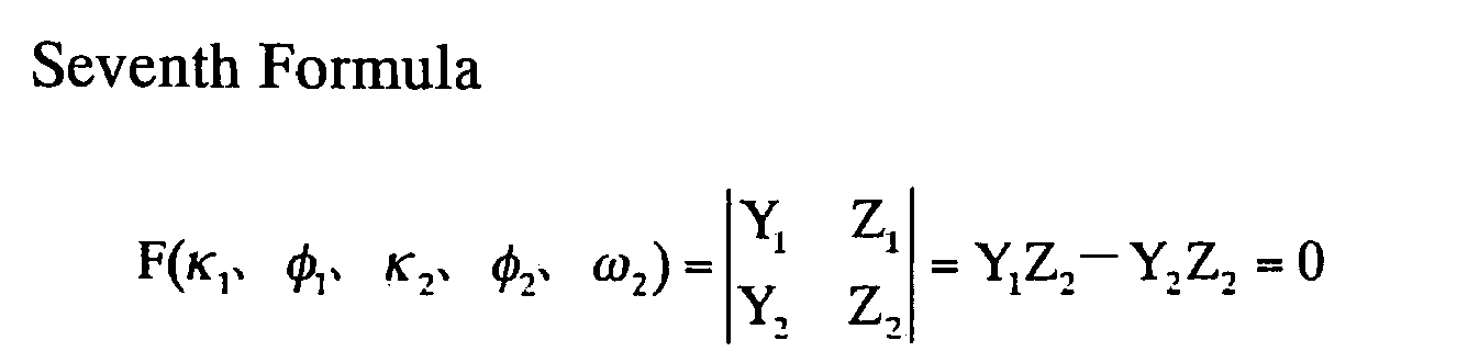
κ1 : Left camera's rotary angle about Z-axis
φ 1 : Left camera's rotary angle about Y-axis
κ2 : Right camera's rotary angle about Z-axis
φ 2 : Right camera's rotary angle about Y-axis
ω2: Right camera's rotary angle about X-axis - Here, the following relationship for converting coordinates is formed between the model coordinate system XYZ and the camera coordinate system xyz.


- Unknown parameters (exterior orientation parameters) are calculated by using the above-described formula according to the steps described below.
- (1) Assume initial approximate values of the unknown parameters (κ1 f 1, κ2, f 2, ω2) to be zero as a rule.
- (2) Expand the coplanar conditional formula of the seventh formula using Taylor's formula about the approximate values, and make it linear. Calculate the differential coefficients from the eighths formula, and make observation formulas.
- (3) Calculate correction amount for the approximate values by the least-squares method.
- (4) Correct the approximate values.
- (5) Use the corrected approximate values, and repeat the steps (1) to (4) until the result converges.
- When the relative orientation is converged, a successive orientation is then performed. In the successive orientation, the tilt and the scale between each model are unified so as to be in the same coordinate system. When this process is performed, successive differences shown in the following ninth formula are calculated. As a result, if the successive differences ΔZj and ΔDj are not more than predetermined values (for example, 0.0005 (1/2000)), it is evaluated that the successive orientation is completed normally.


(Xj l' Yj l' Zj l) : The j-th left model in the unified coordinate system
(Xj r' Yj r' Zj r) : The j-th right model in the unified coordinate system - Next, the exterior orientation parameters are corrected. The positional data of the
position measuring unit 4 and the postural data of theposture measuring unit 5 include the difference between the photographing timing of the image and the obtaining timings of the positional data of theposition measuring unit 4 or the postural data of theposture measuring unit 5. The exterior orientation parameters are corrected after this positional data of theposition measuring unit 4 and this postural data of theposture measuring unit 5 are evaluated. The method for correcting the exterior orientation parameters (position and posture of the camera) will be described hereinafter. - The positional data obtained from the position measuring unit 4 (a GPS or an IMU) have specific accuracy according to each device. For example, when the accuracy is represented as σ, 2σ, 3σ, or the like is used for evaluation values (threshold values) of the positional data of the GPS and the IMU. The positional data of the GPS and the IMU include the error based on the difference between the photographing timing of the image and the obtaining timing of the positional data of the GPS and the IMU. If the positional data of the GPS and the IMU are out of the range of the threshold value, the position of the camera calculated from the image is selected. On the other hand, if these positional data of the GPS and the IMU are in the range of the threshold value, the positional data of the GPS and the IMU are selected. The offset between the mounting position of the camera and the mounting position of the GPS or the IMU is preliminary corrected.
- A method for calculating an error in the positional data of the GPS will be described hereinafter. Generally, the time of the GPS is not synchronized with the time of the camera. This is because synchronization of the time of the GPS and the time of the camera requires a large investment and therefore is practically difficult to realize. Therefore, in the present invention, the obtaining time of the positional data of the GPS and the photographing time of the image are converted to a reference time output from the
reference clock 6. The converted time compensates transmission delay of the positional data and transmission delay of the image data. - The frame rate of the moving image do not coincide with the obtaining rate of the positional data of the GPS, whereby the photographing timing of the image do not synchronize with the obtaining timing of the positional data of the GPS. Therefore, the error in the positional data of the GPS includes the error based on the difference between the photographing timing of the image and the obtaining timing of the positional data of the GPS.
-
Fig. 7A is a timing chart in a case in which a photographing timing of an image is not synchronized with obtaining timing of positional data of a GPS, andFig. 7B is a timing chart in a case in which a photographing timing of an image is synchronized with obtaining timing of positional data of a GPS. - As shown in
Fig. 7A , it is assumed that the difference of the photographing timing of the image and the obtaining timing of the positional data of the GPS is represented as Δt. When the camera moves at a rate v, an error Et in the positional data of the GPS is represented as the following tenth formula.
- When the
reference clock 6 is not used, the value of Δt in the tenth formula is usually unknown. In this case, if the frame rate of the moving image is set to be 30 fps, and the obtaining rate of the positional data of the GPS is set to be 1 fps, it can be assumed that the value of Δt is plus orminus 1/30 seconds at most as shown inFig. 7B . The position measurement device may be structured to change the value of Δt. - When the
reference clock 6 is used, the photographing time of the image and the obtaining time of the positional data of the GPS are represented by the same time axis according to thereference clock 6. Therefore, the time difference between the obtaining time of the positional data of the GPS and the photographing time of an image, which is photographed at a time nearest to the obtaining time, is represented as Δt. The value of Δt shown inFig. 7A is obtained by calculating a difference of the photographing time of the image and the obtaining time of the positional data of the GPS. - The rate v is calculated from a moving distance of the characteristic point in the moving image and the frame rate of the moving image. The following eleventh formula is a formula for computation of the rate v. For example, when (Xi - Xi-1) = 0.1 m, and the frame rate is 30 fps, v = 3 m/seconds. Accordingly, the error Et in the positional data of the GPS comes to 3 × (1/30) = 0.1 m.
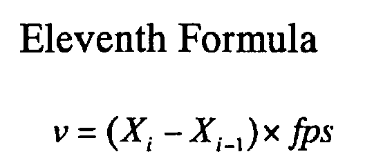
Xi : Position coordinate of the characteristic point in i frame
X i-1: Position coordinate of the characteristic point in i-1 frame
fps : Frame rate (frame/sec) - Moreover, positioning accuracy specific for the GPS is evaluated. The positioning accuracy of the GPS varies depending on values of a satellite position (DOP: Dilution of Precision), multipath, link quality (LQ), convergence estimation of positioning calculation, and the like. For example, in a case of a RTK-GPS (Real Time Kinematic GPS) system, a positioning mode is changed in real time according to a position of a GPS satellite, effects of multipath affected by surrounding environment, correction information from a control station, and the like. The following Table 1 schematically shows positioning accuracy in each positioning mode.
Table 1 Stand-alone positioning mode Positioning accuracy 3 to 10 m C/A code RTK positioning mode Positioning accuracy 1 to 3 m RTK-float posiitoning mode Positioning accuracy 0.6 to 1 m RTK-fix positioning mode Positioning accuracy 0.01 to 0.03 m - Therefore, if the positioning accuracy of the GPS is represented as GPSrtke, a total error STALL in the positional data of the GPS including the difference of the photographing timing of the image and the obtaining timing of the positional data of the GPS is represented by a twelfth formula. For example, when Et = 0.1 m, and GPSrtke = 0.03 m in the RTK-fix positioning mode, the total error in the positional data of the GPS comes to ETALL = 0.13 m. When a threshold is set to be 3σ in the RTK-fix positioning mode, the threshold value comes to 0.03 × 3 = 0.09 m. In this case, since the value of EtALL is greater than the threshold value, the exterior orientation parameters (position of the camera) calculated from the image is used instead of the positional data of the GPS.

- Whether the exterior orientation parameters (position of the camera) will be corrected or not may be selected depending on which positioning mode is used for measuring the positional data of the GPS, among the positioning mode shown in the Table 1. For example, only the RTK-fix positioning mode is selected to be used. In this case, the exterior orientation parameters calculated from the image are selected.
- After the error in the positional data of the GPS is calculated, the positional data of the GPS, which includes the difference between the photographing timing of the image and the obtaining timing of the positional data of the GPS, is evaluated.
Fig. 8A shows a case in which positional data of a GPS is in the range of a predetermined threshold value, and Fig. SB shows a case in which positional data of a GPS is out of the range of a predetermined threshold value. In this case, the positional data of the GPS includes a difference between a photographing timing of an image and obtaining timing of the positional data of the GPS. As shown inFig. 8A , if the positional data EtALL of the GPS is in the range of the predetermined threshold value, the positional data of the GPS is selected. On the other hand, as shown inFig. 8B , if the positional data EtALL of the GPS is out of the range of the predetermined threshold value, the exterior orientation parameters (position of the camera) calculated from the image is selected. - The postural data obtained from the posture measuring unit 5 (an posture sensor or an IMU) is evaluated by using 2σ or 3σ of an assumable accuracy σ as an evaluation value (threshold value). The postural data includes an error based on the difference between the photographing timing of the image and the obtaining timing of the postural data of the posture sensor and the IMU. That is, if this postural data is out of the range of the threshold value, the posture of the camera calculated from the image is selected. On the other hand, if this postural data is in the range of the threshold value, the postural data of the
posture measuring unit 5 is selected. - The postural data of the
posture measuring unit 5 is made of three rotary angles (ω, ϕ, κ) of camera coordinate axes, and one of the rotary angles may be evaluated, or two or all three of the rotary angles may be evaluated. In this case, whether the rotary angles are used or not is set depending on the accuracy of the posture sensor and the IMU. - A method for calculating an error in the posture sensor will be described hereinafter.
Fig. 9A shows a relationship between a measuring time of postural data of a posture sensor and an accumulated error. Generally, in the postural data of the posture sensor, since acceleration may be integrated or double integrated essentially, error accumulates as time passes. It is assumed that a measuring time from setting of an initial value or from resetting of the hardware is represented as t, and an accumulated error is approximated to an exponential function of 1.05t-1. In this case, errors Ext, Eyt, and Ezt of the postural data of the posture sensor are represented by the following thirteenth formula. For example, when t = 10 seconds, Ext, Eyt, Ezt = 0.63°. The accumulated error differs from the posture sensor, the IMU, and the measuring axis, and therefore, the approximate formula is formed respectively.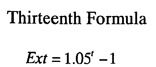


- In the present invention, although the time of the posture sensor is not synchronized with the time of the camera, the obtaining time of the postural data and the photographing time of the image are converted to the reference time output from the
reference clock 6. The converted time compensates the transmission delay of the postural data of the posture sensor and the transmission delay of the image data. - The frame rate of the moving image does not coincide with the obtaining rate of the postural data of the posture sensor, whereby the photographing timing of the image does not synchronized with the obtaining timing of the postural data of the posture sensor. Therefore, the error in the postural data of the posture sensor includes the error based on the difference between the photographing timing of the image and the obtaining timing of the postural data of the posture sensor.
-
Fig. 9B is a timing chart in a case in which a photographing timing of an image is not synchronized with obtaining timing of postural data of a posture sensor. As shown inFig. 9B , it is assumed that the difference of the photographing timing of the image and the obtaining timing of the postural data of the posture sensor is represented as Δt, and the posture of the camera is changed at angle rates vx, vy, vz at that time. The errors Ext, Eyt, Ezt of the postural data of the posture sensor are represented by the following fourteenth formula.


- When the
reference clock 6 is used, the photographing time of the image and the obtaining time of the postural data of the posture sensor are represented by the same time axis according to thereference clock 6. Therefore, time difference between the obtaining time of the postural data of the posture sensor and the photographing time of an image, which is photographed at a time nearest to the obtaining time, is represented as Δt. The value of Δt shown inFig. 9B is obtained by calculating a difference of the photographing time of the image and the obtaining time of the postural data of the posture sensor. For the angle rates vx, vy, vz, values obtained from the posture sensor and the IMU are used. For example, when Vx = 1.25°/seconds, vy = 3.86°/seconds, vz =10.12°/seconds, and Δt = 1/120 seconds, Ext = 0.64°, Eyt = 0.66°, and Ezt =0.71°. - Moreover, if a specific accuracy IMUe of the posture sensor is included, total errors ExtALL, EytALL, EztALL of the postural data of the posture sensor are represented by the following fifteenth formula.


- If the total errors ExtALL, EytALL, EztALL of the postural data of the posture sensor are out of the range of the predetermined threshold values, exterior orientation parameters (posture of the camera) calculated from the image are selected. If the total errors ExtALL, EytALL, EztALL of the postural data of the posture sensor are in the range of the predetermined threshold values, the postural data of the posture sensor is selected.
- After the exterior orientation parameters are corrected, a bundle adjustment is performed on the exterior orientation parameters and the three-dimensional coordinates of the characteristic points in one or more images, or all images at the same time. The bundle adjustment method uses a collinearity condition such that light fluxes (bundles) connecting a point in the objective space, a point in the image, and the projection center, must be on the same straight line. In the bundle adjustment, an observation equation is formed for each of the light flux in each image based on the collinearity condition, and simultaneous adjustment is performed by the least-squares method. The collinearity conditional formula is represented as the following sixteenth formula.


- In the bundle adjustment, a successive approximation method is used. Specifically, approximate values of the three-dimensional coordinates of the reference point and the characteristic points, and approximate values of the exterior orientation parameters, are represented as (X', Y', Z') and (X0', Y0', Z0, ω', f ', κ'), respectively. Then, correction amounts are added to the approximate values, whereby (X' + ΔX, Y' + ΔY, Z' + ΔZ) and (X0' + ΔX0, Y0' + ΔY0, Z0' + ΔZ0, ω'+ Δω, f ' + Δf, κ' + Δκ) are obtained. These approximate values including the correction amounts are used as true values of the three-dimensional coordinates of the reference point and the characteristic points and the exterior orientation parameters. Measured values of the image coordinates corresponding to the reference point and the characteristic points are represented as (x', y'). Then, errors are added to the measured values, whereby (x' + dx, y' + dy) are obtained and are used as true values of the image coordinates corresponding to the reference point and the characteristic points. The approximate values including the correction amounts and the measured values including the errors are substituted for the collinearity conditional formula (sixteenth formula) of one or more images. The sixteenth formula is expanded by using Taylor's formula about the approximate value and is linearized. Then, correction amounts are calculated by the least-squares method. The approximate values are corrected according to the calculated correction amounts, and the above calculations are repeated in the same manner, whereby convergence results are obtained.
- In this case, the symbols Δx and Δy represent correction terms of the internal orientation parameters (focal point distance, principal point position, lens distortion coefficient). The following eighteenth formula represents a compensatory model of internal orientation parameters in a case in which a lens has distortion in a radiation direction. The internal orientation parameters are adjusted at the same time by using the eighteenth formula. That is, the bundle adjustment includes self calibration.


c : Focal point distance x,y,z : Image coordinates
X,Y,Z :Objective space coodinates (reference point, unknown point)
X 0,Y 0,Z 0: Projection centers (photographing position of a camera)
a 11∼a 33: Posture of a camera (parameters of 3 × 3 rotation matrix)
Δx, Δy : Correction terms of internal orientation of a camera
ω,φ,κ : Posture of a camera (angles of x,y,z axes rotated from X, Y,Z axes)
k 1 ,k 2 :Lens distortion coefficients in radiation direction - Based on the exterior orientation parameters which are bundle adjusted, three-dimensional coordinates of subsequently detected characteristic points are calculated. These characteristic points were detected in an area in which the density of the characteristic points was decreased. In this calculation, the forward intersection method or the DLT method may be used. As shown in
Fig. 4 , the calculation of the three-dimensional coordinates in the step S13 may be performed before the bundle adjustment (step S12). -
Fig. 10 is an explanatory diagram for explaining a forward intersection method. In the forward intersection method, directions from at least two of known points (O1, O2) to an unknown point P are observed, and the position of the unknown point P is fixed as an intersection point of these directional lines. - As shown in
Fig. 10 , a coordinate system of an objective space is assumed to be O-XYZ. Coordinates (X01, Y01, Z01) of a projection center O1 of a camera and tilts(ω1, f 1, κ1) of camera coordinate axes in a prior frame image, and coordinates (X02, Y02, Z02) of a projection center O2 the camera and tilts (posture) (ω2, f 2, κ2) of camera coordinate axes in a current frame image, are known values. In addition, internal orientation parameters (focal point distance, principal point position, lens distortion coefficient) are also known valuers. If a point p1 (x1, y1) in the prior frame image and a point p2 (x2, y2) corresponding to the point p1 in the current frame image are known, an unknown point P (X, Y, Z) in the objective space is fixed as an intersection point of a light ray (O1p1) and a light ray (O2p2). In this case, the two light rays do not intersect because there are essentially errors, and therefore, the intersection position is obtained by the least-squares method. - Specifically, a collinearity conditional formula (sixteenth formula) for the two light rays is formed, and the exterior orientation parameters, the internal orientation parameters, and the image coordinates of the corresponding point, all of which are known values, are substituted for the sixteenth formula. Moreover, approximate values including correction amounts of the unknown point P are substituted for the collinearity conditional formula. In this case, the approximate values of the unknown point P are represented as (X', Y', Z'), and the approximate values including the correction amounts are represented as (X' + ΔX, Y' + ΔY, Z' + ΔZ). The sixteenth formula is expanded by using Taylor's formula about the approximate value and is linearized. Then, the correction amounts are calculated by the least-squares method. The approximate values are corrected according to the calculated correction amounts, and the above calculations are repeated in the same manner, whereby convergence results are obtained. According to this step, the three-dimensional coordinates P (X, Y, Z) of the characteristic point is calculated.
- After the three-dimensional coordinates of the subsequently detected characteristic points are calculated, whether the image which is currently processed is the final image or not is evaluated. When the image which is currently processed is not the final image, exterior orientation parameters of a following image are calculated by returning to the step S10. Then, the steps S10 to S14 are repeated until the image is evaluated as the final image. When the image which is currently processed is the final image, the process is finished.
- According to the first embodiment, the difference between the photographing timing of the image and the obtaining timing of the positional data of the
position measuring unit 4 or the postural data of theposture measuring unit 5, is used as an error of the positional data of theposition measuring unit 4 or the postural data of theposture measuring unit 5. The positional data of theposition measuring unit 4 and the postural data of theposture measuring unit 5 include this difference. The exterior orientation parameters are corrected depending on whether this positional data and this postural data are in the range of predetermined threshold values or not. Even when the photographing timing of the image do not synchronize with the obtaining timing of the positional data of theposition measuring unit 4 and the postural data of theposture measuring unit 5, the exterior orientation parameters are appropriately corrected. Therefore, the errors are decreased. - In the errors of the positional data of the
position measuring unit 4 and the postural data of theposture measuring unit 5, specific accuracy in the positional data and the postural data is added to the error based on the time difference Δt. Therefore, the exterior orientation parameters calculated from the image are appropriately corrected. - Specifically, in the case of RTK-GPS (Real Time Kinematic GPS), the positioning mode is changed in real time based on a position of a GPS satellite, multipath affected by surrounding environment, correction information from a control station, and the like, which may affect the accuracy. Accordingly, by changing the threshold value for correcting the exterior orientation parameters based on the positioning mode, the exterior orientation parameters are appropriately corrected.
- On the other hand, in the postural data of the
posture measuring unit 5, the error tends to accumulate due to the function of the measurement and the measuring time t. Therefore, by including the accuracy based on the measuring time t of the postural data, the exterior orientation parameters are appropriately corrected. - A modification of the first embodiment will be described hereinafter. In the second embodiment, change of photographing scenes and shift of a photographing unit are evaluated based on at least one selected from the group consisting of directions and distances of tracks of the characteristic points, a distribution rate of the characteristic points, an overlapping rate, and a vertical parallax.
-
Fig. 11 is a functional block diagram of a position measurement device. The position measurement program further includes animage analyzing section 20 compared to the position measurement program shown inFig. 2 . Moreover, the position measurement program includes an exterior orientationparameter evaluating section 21 instead of the exterior orientationparameter correcting section 14 inFig. 2 . - In the
image analyzing section 20, change of photographing scenes and shift of a photographing unit are analyzed based on track directions of the characteristic points, moved distances of the characteristic points, a distribution rate of the characteristic points, an overlapping rate, and a vertical parallax. - In the exterior orientation
parameter evaluating section 21, the exterior orientation parameters calculated from the image are evaluated based on the analyzed result of theimage analyzing section 20. When the change of the photographing scenes is evaluated to be relatively great, the exterior orientation parameters are corrected by using the positional data obtained from theposition measuring unit 4 and the postural data obtained from theposture measuring unit 5. When the change of the photographing scenes is evaluated to be relatively small, the exterior orientation parameters calculated from the image is selected. - Next, overall operation of the position measurement device will be described.
Figs. 12 and13 are flow charts showing operations of the position measurement device. - A process of calculating three-dimensional coordinates and exterior orientation parameters in the step S5 related to the second embodiment will be described in detail hereinafter. As shown in
Fig. 12 , the process of calculating the three-dimensional coordinates and the exterior orientation parameters in the step S5 includes a step of calculation of the exterior orientation parameters (step S10), a step of evaluation of the calculated exterior orientation parameters (step S16), a step of bundle adjustment of the evaluated exterior orientation parameters and the three-dimensional coordinates of known points (step S12), and a step of calculation of three-dimensional coordinates of subsequently detected characteristic points (step S13). - The bundle adjustment (step S12) may be performed before the calculation of the three-dimensional coordinates of the subsequently detected characteristic points (
Fig. 12 ) or after the calculation of the three-dimensional coordinates of the subsequently detected characteristic points (Fig. 13 ). In the case shown inFig. 12 , the calculation accuracy of the three-dimensional coordinates of the subsequently detected characteristic points is improved. In the case shown inFig. 13 , since the three-dimensional coordinates of the subsequently detected characteristic points are calculated based on the evaluated exterior orientation parameters, the function is the same as the function in the case shown inFig. 12 . - The calculation of the exterior orientation parameters is based on the three-dimensional coordinates of the reference point or the characteristic points in which the three-dimensional coordinates are previously calculated, and is also based on the image coordinates obtained by tracking the characteristic points. Therefore, the accuracy of the exterior orientation parameters depends on the tracking accuracy of the characteristic points. The tracking accuracy of the characteristic points depends on remarkable change of the photographing scenes and shift of the photographing unit. Therefore, depending on change of the photographing scenes and shift of the photographing unit, errors may occur or calculations may not be performable.
- Accordingly, when change of the photographing scenes and shift of the photographing unit are great, and the exterior orientation parameters calculated from the image are not reliable, positional data obtained from the
position measuring unit 4 and postural data obtained from theposture measuring unit 5 are used. In this case, the exterior orientation parameters calculated from the image are not used. - The amount of the change of the photographing scenes and the amount of the shift of the photographing unit are evaluated based on directions and distances of tracks of the characteristic points, a distribution rate of the characteristic points, an overlapping rate, and a vertical parallax. This evaluation is performed by the
image analyzing section 20. A method for evaluating the change of the photographing scenes will be described hereinafter. Evaluation according to directions and distances of tracks of the characteristic points -
Fig. 14A shows an image in which track directions of characteristic points in a prior frame and track directions of subsequently detected characteristic points are different, andFig. 14B shows an image in which track distances of characteristic points in a prior frame and track distances of subsequently detected characteristic points are different. - For example, as shown in
Fig. 14A , when a camera is shifted to the right direction, characteristic points are subsequently detected and are increased in an area in which the density of the characteristic points is decreased. When the track directions of the subsequently detected characteristic points are greatly changed by 90 degrees, 180 degrees, and so on, with respect to the track directions of the prior characteristic points, the photographing scene is evaluated to be changed, or the photographing unit is evaluated to be shifted. In this case, the exterior orientation parameters calculated from the image are evaluated to have low reliability. Then, the exterior orientation parameters are corrected by using the positional data obtained from theposition measuring section 4 and the postural data obtained from theposture measuring unit 5. - The change of the track direction of the characteristic point is defined as an angle θ between a track vector "a" of a characteristic point in a prior frame and a track vector "b" of a subsequently detected characteristic point. This angle is calculated from a definition of the inner product represented by a nineteenth formula

- Furthermore, for example, as shown in
Fig. 14B , when tracking distances of the subsequently detected characteristic points are greatly changed by double, quadruple, etc., with respect to the prior tracking distances, the photographing scene is evaluated to be changed. In this case, the exterior orientation parameters calculated from the image are evaluated to have low reliability. Then, the exterior orientation parameters are corrected by using the positional data obtained from theposition measuring unit 4 and the postural data obtained from theposture measuring unit 5. - The change of the tracking distance is the difference between the length of the track vector "a" of the characteristic point in the prior frame and the length of the track vector "b" of the subsequently detected characteristic point. This difference is calculated from the following twentieth formula. Threshold values for directions and distances of the tracks of the characteristic points are adjustable.

- When the change of the photographing scene and the shift of the photographing unit are great, there may be cases in which the characteristic points cannot be tracked, and the points are partially distributed in an image.
Fig. 15A shows an image in which a distribution rate of the characteristic points is zero,Fig. 15B shows an image in which a distribution rate of the characteristic points is negative, andFig. 15C shows an image in which a distribution rate of the characteristic points is positive. - When the camera is shifted in a horizontal direction, a distribution rate of the characteristic points in the horizontal direction is calculated as a total value of X coordinates of the characteristic points. In this case, the center of the image is assumed to be origin (0, 0). For example, in the case shown in
Fig. 15A , since the characteristic points are uniformly distributed in the overall image, the total value of the X coordinates comes to zero. In the case shown inFig. 15B , since the characteristic points are distributed on the left side of the image, the total value of the X coordinates comes to negative. In the case shown inFig. 15C , since the characteristic points are distributed on the right side of the image, the total value of the X coordinates comes to positive. - When the camera is shifted in a vertical direction, the distribution rate of the characteristic points in the vertical direction is calculated as a total value of Y coordinates of the characteristic points. In this case, the center of the image is assumed to be origin (0, 0). Therefore, the distribution rate of the characteristic points in the vertical direction may be calculated from the total value of the Y coordinates of the characteristic points.
- When the change of the photographing scene and the shift of the photographing unit are great, there may be cases in which characteristic points overlapping in the prior and the subsequent frames are partially distributed. These overlapping characteristic points are points obtained by tracking the characteristic points.
Fig. 16A shows an image in which characteristic points overlapping in prior and subsequent frames are partially distributed, andFig. 16B shows an image in which characteristic points overlapping in prior and subsequent frames are not partially distributed. - As shown in
Fig. 16A , when the overlapping characteristic points are partially distributed, the exterior orientation parameters calculated from the image are evaluated to have low reliability. In this case, the exterior orientation parameters are corrected by using the positional data obtained from theposition measuring unit 4 and the postural data obtained from theposition measuring unit 5. As shown inFig. 16B , when the overlapping characteristic points are not partially distributed, the exterior orientation parameters calculated from the image are evaluated to have high reliability. In this case, the exterior orientation parameters calculated from the image are used. - The distribution condition (overlapping rate) of the overlapping characteristic points is evaluated by the method for calculating the distribution rate of the characteristic points. Threshold values for the distribution rate of the characteristic points and the overlapping rate are adjustable.
- The vertical parallax is a difference between y coordinates of corresponding points in two images that are stereographed. That is, the vertical parallax is a difference of coordinate values in a direction intersecting the baseline direction of the stereo images at a right angle. The stereo images are a pair of images and are made of two images photographed by cameras in a condition in which the optical axes are parallel, and directions intersecting a baseline direction at a right angle are parallel. Therefore, the y coordinates of the corresponding points in the two images are equal, whereby the vertical parallax in the stereo images is usually zero pixel.
- If the photographing unit is shifted, the vertical parallax does not come to zero pixel. Therefore, when there is not less than 1 pixel of the vertical parallax, the exterior orientation parameters calculated from the image are not used, and the positional data obtained from the
position measuring unit 4 and the postural data obtained from theposture measuring unit 5 are used. - The vertical parallax is obtained by calculating the difference between the y coordinate of the characteristic point in a prior frame and the y coordinate of the characteristic point in a current frame. A threshold value for the vertical parallax is adjustable.
- The change of the photographing scene and the shift of the photographing unit may be evaluated based on the value obtained by multiplying more than one or all of the parameters selected from the group consisting of the directions and the distances of the tracks of the characteristic points, the distribution rate of the characteristic points, the overlapping rate, and the vertical parallax.
- According to the second embodiment, the change of the photographing scene and the shift of the photographing unit are evaluated based on at least one selected from the group consisting of the directions and the distances of the tracks of the characteristic points, the distribution rate of the characteristic points, the overlapping rate, and the vertical parallax. The change of the photographing scene and the shift of the photographing unit cause difficulty in tracking of the characteristic points and cause decrease in the accuracy of the exterior orientation parameters calculated from the images. Therefore, when the change of the photographing scene and the shift of the photographing unit are relatively great, the exterior orientation parameters calculated from the images are evaluated to have low reliability. On the other hand, when the change of the photographing scene and the shift of the photographing unit are relatively small, the exterior orientation parameters calculated from the images are evaluated to have high reliability.
- When the exterior orientation parameters calculated from the images are evaluated to have low reliability, the positional data obtained from the
position measuring unit 4 and the postural data obtained from theposture measuring unit 5 are used whereas the exterior orientation parameters calculated from the images are not used. According to this embodiment, errors due to the change of the photographing scene and the shift of the photographing unit are decreased. - A modification of the first and the second embodiments will be described hereinafter. In the third embodiment, a weighted bundle adjustment is performed.
-
Fig. 17A is a schematic view showing a bundle adjustment related to the first and the second embodiments. As shown inFig. 17A , in the first embodiment, the exterior orientation parameters calculated from the camera are corrected based on the error caused by the time difference Δt of the positional data of the GPS or the postural data of the posture sensor. In the second embodiment, the exterior orientation parameters calculated from the camera are evaluated based on at least one selected from the group consisting of the directions and the distances of the tracks of the characteristic points, the distribution rate of the characteristic points, the overlapping rate, and the vertical parallax. Then, best data are selected from the group consisting of the positional data of the GPS, the postural data of the posture sensor, and the exterior orientation parameters calculated from the camera, for the exterior orientation parameters to be bundle adjusted. The bundle adjustment is performed based on these selected exterior orientation parameters. Therefore, the bundle adjustment is performed based on the data shown in a dotted frame area inFig. 17A . - On the other hand, in the third embodiment, the exterior orientation parameters are not corrected by using best data, but the positional data of the GPS, the postural data of the posture sensor, and the exterior orientation parameters calculated from the camera, are weighted and are bundle adjusted.
Fig. 17B is a schematic view showing a weighted bundle adjustment related to the third embodiment. As shown inFig. 17B , weights of data having low accuracy are decreased, and weights of data having high accuracy are increased. As a result, the exterior orientation parameters and the three-dimensional coordinates of the characteristic points are bundle adjusted so as to be in the area of the solid lined frame shown inFig. 17B . - The weight is calculated based on the accuracy of each data. If the accuracy of each data is represented as σ, the weight w is calculated from a twenty-first formula. The accuracy of each data will be described hereinafter.

- The accuracy of the positional data of the GPS and the postural data of the posture sensor are based on an error caused by the difference between the photographing timing of the image and the obtaining timing of the positional data of the GPS or the postural data of the posture sensor, and are also based on specific accuracy of the positional data of the GPS and the postural data of the posture sensor.
- Generally, the times of the GPS and the posture sensor are not synchronized with the time of the camera. Therefore, in the present invention, the obtaining time of the positional data of the GPS and the photographing time of the image are converted to the reference time outputted from the
reference clock 6. The converted times include the transmission delay of the positional data and the postural data and the transmission delay of the image data. - The frame rate of the moving image do not coincide with the obtaining rate of the GPS and the posture sensor, whereby the photographing timing of the image do not synchronize with the obtaining timing of the positional data of the GPS and the postural data of the posture sensor. Therefore, the accuracy of the GPS and the posture sensor include an error based on the difference between the photographing timing of the image and the obtaining timing of the positional data of the GPS or the postural data of the posture sensor.
- It is assumed that the difference of the photographing timing of the image and the obtaining timing of the positional data of the GPS or the postural data of the posture sensor is represented as Δt. When the camera moves at a rate v (angle rate vx, vy, vz), an error Et of the positional data of the GPS is represented as a twenty-second formula, and errors Ext, Eyt, Ezt of the postural data of the posture sensor are represented as a twenty-third formula.


- The photographing time of the image and the obtaining time of the positional data of the GPS and the postural data of the posture sensor are represented by the same time axis according to the
reference clock 6. Therefore, time difference between the obtaining time of the positional data of the GPS and the postural data of the posture sensor and the photographing time of an image, which is photographed at a time nearest to the obtaining time, is represented as Δt. - The rate v is calculated from a moving distance of the characteristic point in the moving image and the frame rate of the moving image. For the angle rate vx, vy, vz, values obtained from the posture sensor and the IMU are used.
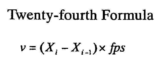
Xi : Position coordinate of the characteristic point in i frame
X i-1: Position coordinate of the characteristic point in i-1 frame
fps : Frame rate (frame/sec) - Next, specific accuracy of the GPS and the posture sensor will be described. The positioning accuracy of the GPS varies depending on values of the satellite position (DOP: Dilution of Precision), the multipath, the link quality (LQ), the convergence estimation of positioning calculation, and the like. For example, in the case of the RTK-GPS (Real Time Kinematic GPS) system, the positioning mode is changed in real time as shown in the Table 1, according to the position of the GPS satellite, the effects of multipath affected by surrounding environment, the correction information from a control station, etc.
- If the positioning accuracy of the GPS is represented as GPSrtke, a total error EtALL of the positional data of the GPS is represented as a twenty-fifth formula.

- In the posture sensor, since acceleration may be integrated or be double integrated essentially, error accumulates as time passes. It is assumed that the measuring time from setting of the initial value or from resetting of the hardware is represented as t, and the accumulated error is approximated to an exponential function of 1.05t-1. In this case, the accuracy of the posture sensor is represented by a twenty-sixth formula. Moreover, if the specific accuracy IMUe of the posture sensor is included in the twenty-sixth formula, the total values ExtALL, EytALL, EztALL of the accuracy of the posture sensor are represented by a twenty-seventh formula.




- The accuracy of the exterior orientation parameters and the three-dimensional coordinates of the characteristic points are obtained based on at least one selected from the group consisting of the directions and the distances of the tracks of the characteristic points, the distribution rate of the characteristic points, the overlapping rate, and the vertical parallax, in the second embodiment. The change of the track direction of the characteristic point is represented as an angle θ between a vector "a" and a vector "b" (tenth formula), and the change of the track distance of the characteristic point is represented as a difference la - bl of the vector "a" and the vector "b" (eleventh formula). Therefore, the accuracy σ is represented as θ or |a - b|.
- The distribution rate of the characteristic points and the overlapping rate are the total values of the X coordinates and the Y coordinates of the characteristic points which have an origin at the center of the image. Therefore, the accuracy σ is represented by an absolute value of the distribution rate or the overlapping rate. Since the vertical parallax is the difference between the y coordinates of the characteristic points in the stereo images, the accuracy σ is represented by an absolute value of the difference between the y coordinates of the characteristic points.
- The accuracy σ of the exterior orientation parameters and the three-dimensional coordinates of the characteristic points may be represented by a value obtained by multiplying more than one or all of the parameters selected from the group consisting of the directions and the distances of the tracks of the characteristic points, the distribution rate of the characteristic points, the overlapping rate, and the vertical parallax.
- Each correction amount in the weighted bundle adjustment is calculated as a value for minimizing the following function G For example, the symbol "w2" represents a weight of the three-dimensional coordinates obtained by the camera, and the symbols "w3" and "w4" represent weights of the exterior orientation parameters.

[ ]: Summation symbol of Gauss
w 1 : Weight of measured values of image coordinates
w 2 : Weight of coordinates of a reference point
w 3 Weight of measured values of angles
w 4 : Weight of coordinates of a photographing point - When the positional data of the GPS and the IMU and the postural data of the posture sensor are included, the following twenty-ninth formula is used and is minimized. For example, the symbol "w5" represents a weight of the positional data of the GPS, the symbol "w6" represents a weight of the positional data of the IMU, and the symbol "w7" represents a weight of the postural data of the posture sensor.

- According to the third embodiment, the exterior orientation parameters and the three-dimensional coordinates of the characteristic points, and also the positional data of the
position measuring unit 4 and the postural data of theposture measuring unit 5, are bundle adjusted at the same time. In this case, each data is weighted and is bundle adjusted, whereby the weights of data having low accuracy are decreased, and the weights of data having high accuracy are increased. Accordingly, the errors of the exterior orientation parameters and the three-dimensional coordinates of the characteristic points are decreased. - The weights of the positional data of the
position measuring unit 4 and the postural data of theposture measuring unit 5 are calculated based on the difference between the photographing timing of the image and the obtaining timing of the positional data of theposition measuring unit 4 or the postural data of theposture measuring unit 5. Therefore, even when the photographing timing of the image do not synchronize with the obtaining timing of the positional data of theposition measuring unit 4 and the postural data of theposture measuring unit 5, the errors of the exterior orientation parameters and the three-dimensional coordinates of the characteristic points are decreased. - The weights of the exterior orientation parameters and the three-dimensional coordinates of the characteristic points are calculated based on at least one selected from the group consisting of the directions and the distances of the tracks of the characteristic points, the distribution rate of the characteristic points, the overlapping rate, and the vertical parallax. The accuracy of the exterior orientation parameters and the three-dimensional coordinates of the characteristic points calculated from the image have strong tendency to depend on the change of the photographing scene and the shift of the photographing unit. The directions and the distances of the tracks of the characteristic points, the distribution rate of the characteristic points, the overlapping rate, and the vertical parallax, are reference for evaluating the change of the photographing scene and the shift of the photographing unit. Therefore, by using these parameters for the weights of exterior orientation parameters and the three-dimensional coordinates of the characteristic points, the errors of the exterior orientation parameters and the three-dimensional coordinates of the characteristic points are decreased.
- A modification of the first to the third embodiments will be described hereinafter. In the fourth embodiment, by removing points having relatively large errors (miscorresponding points) from the corresponding points which are tracked, calculation accuracy of the exterior orientation parameters and the three-dimensional coordinates of the characteristic points are improved.
-
Figs. 18 to 20 are flow charts including a step of removing miscorresponding points. The step of removing miscorresponding points is performed after the bundle adjustment (Figs. 18 and19 ) or before the calculation of the exterior orientation parameters (Fig. 20 ). In the case shown inFig. 18 , the calculation accuracy of the exterior orientation parameters of the subsequent frames is improved. In the case shown inFig. 19 , since the three-dimensional coordinates of the miscorresponding points which are removed are not calculated, the calculation process becomes more efficient. In the case shown inFig. 20 , the calculation accuracy of the exterior orientation parameters of the current frame is improved. - In the method for removing the miscorresponding points, the backward projection or the vertical parallax calculated by the relative orientation is used. These removal methods may be used separately or may be used together depending on the photographing conditions. For example, the removing of the miscorresponding points by the backward projection using a single photo orientation is used when the change of the scene is large because the miscorresponding points are removed based on one image. On the other hand, the removing of the miscorresponding points by the relative orientation is used when the change of the scene is small because the miscorresponding points are removed based on plural images.
- In order to estimate a threshold value for evaluating the errors, a robust estimation may be used. For example, a LMedS estimation (Least Median of Squares estimation), a RANSAC estimation (RANdom SAmple Consensus estimation), and an M estimation may be used. Specifically, the LMedS estimation is superior in robustness, and the miscorresponding points are automatically removed even when the error range is unknown.
- The threshold value for evaluating the errors may be set to be a fixed threshold value which is adjustable, instead of using the robust estimation. According to this embodiment, the calculation process is simple, whereby the processing speed is improved.
- The fourth embodiment of the present invention will be described according to a flow chart shown in
Fig. 21 hereinafter.Fig. 21A is a flow chart for removing the miscorresponding points by the backward projection, andFig. 21B is a flow chart for removing the miscorresponding points by using the vertical parallax. - First, corresponding points which are tracked are randomly sampled (step S20). Then, image coordinates (x', y') of a corresponding point with respect to each of the sampled point are calculated based on the exterior orientation parameters calculated by the backward intersection method (single photo orientation or DLT method) and the three-dimensional coordinates of the tracked corresponding point. For example, in a case of the single photo orientation, by substituting the exterior orientation parameters (X0, Y0, Z0, ω, f , κ) and the three-dimensional coordinates (X, Y, Z) of the corresponding point for the collinearity conditional formula of the sixth formula, the image coordinates (x', y') are inversely calculated (step S21).
- In each of the sampled points, a square of a residual value between the image coordinates (x', y') obtained by the backward intersection method and the image coordinates (x, y) of the tracked corresponding point is calculated, and a central value of the squares of the residual values is calculated (step S22). Then, the steps S20 to S22 are repeated, and the minimum value (LMedS) of the central value is calculated (step S23). A standard of the LMedS is shown in the following thirtieth formula.

i : Data number
ε : Error between the image coordinates of the tracked corresponding point and the image coordinates calculated by the backward intersection method
med () : Center value
min () : Minimum value - The number of times required to repeat the steps S20 to S22 is defined by using probability in which an exception value is not included at least one time in q times of the random sampling. For example, if the rate of the exception value in the whole data is represented as "c", the probability P is represented by the following thirty-first formula. For example, when c = 0.3 and n = 3, q = 11 in order to obtain P = 0.01.

n : Number of data
c : Rate of outliers in the overall data
q : Times required to repeat
P : Rate in which an exception value is not included at least one time in q times of the random sampling - Then, points having large errors are removed by using the value of the LMedS calculated in the step S23 as a threshold value (step S24).
- First, corresponding points in the prior and the subsequent images are randomly sampled (step S30). Then, as shown in
Fig. 6 , the sampled corresponding points (P1, P2) have a point P in the real space, and three-dimensional coordinates of the point P are reprojected on a stereo image shown by the dotted lines according to the coplanar conditional formula (sixth formula) of the relative orientation (step S31). - The vertical parallax is calculated as the difference between the y coordinates of the two corresponding points that are reprojected. The vertical parallax is a difference of y-coordinates of corresponding points in two images that are stereographed, that is, a difference of coordinate values in a direction intersecting a baseline direction of the stereo images at a right angle. The stereo images are a pair of images and are made of two images photographed by cameras in a condition in which the optical axes are parallel, and directions intersecting a baseline direction at a right angle are parallel. Then, a square of the vertical parallax is calculated, and the central value of the squares of the vertical parallaxes is calculated (step S32). The steps S30 to S32 are repeated, and the minimum value (LMdeS) of the central value is obtained (step S33). The standard of the LMedS is represented by the thirtieth formula.
- Then, points having large errors are removed by using the value of the LMedS calculated in the step S33 as a threshold value (step S34). Advantages of the fourth embodiment
- The tracking results of the characteristic points include numerous miscorresponding points. Therefore, the exterior orientation parameters and the three-dimensional coordinates of the characteristic points calculated based on the miscorresponding points are inferior in the accuracy. However, by removing the miscorresponding points, the calculation accuracy of the exterior orientation parameters and the three-dimensional coordinates of the characteristic points are improved, and the errors are decreased.
- Moreover, the method for removing the miscorresponding points (residual value calculated by the backward projection or the vertical parallax calculated by the relative orientation) is selected based on the change of the photographing conditions. Therefore, the exterior orientation parameters and the three-dimensional coordinates of the characteristic points are calculated regardless of the change of the photographing conditions.
- In the LMedS method, compared to the least-squares method, even when numerous outliers are included in the data, the outliers are robustly estimated. Accordingly, the errors of the exterior orientation parameters and the three-dimensional coordinates of the characteristic points are decreased.
- The present invention can be utilized in a position measurement method, a position measurement device, and programs therefor. In this case, the position measurement method, the position measurement device, and the programs therefor may be used for measuring a position and a posture, at which photograph is performed, and a three-dimensional position of an object, based on moving images.
Claims (30)
- A position measurement method comprising:an initial value calculating step for calculating initial values of exterior orientation parameters, which are a photographing position and a photographing posture, based on known points in an initial image or a photographing position and/or a photographing posture measured outside;an exterior orientation parameter-calculating step for calculating exterior orientation parameters, based on known points in a moving image which follows the initial image used in the initial value calculating step, or characteristic points in which three-dimensional coordinates are already calculated;an exterior orientation parameter correcting step for correcting the exterior orientation parameters calculated in the exterior orientation parameter-calculating step, based on difference between photographing timing of the image and obtaining timing of the photographing position and/or the photographing posture measured outside;a bundle-adjusting step for simultaneously adjusting a bundle of the exterior orientation parameters of one or more images and the three-dimensional coordinates of the characteristic points, based on the exterior orientation parameters corrected by the exterior orientation parameter correcting step;a three-dimensional coordinate calculating step for calculating three-dimensional coordinates of characteristic points subsequently detected in an area in which the density of the characteristic points is decreased, based on the exterior orientation parameters adjusted bundle thereof; anda repeating step for repeating processing from the exterior orientation parameter-calculating step to the three-dimensional coordinate calculating step until the image becomes a final image.
- The position measurement method according to Claim 1, wherein the exterior orientation parameter correcting step corrects the exterior orientation parameters, based on the difference between the photographing timing of the image and the obtaining timing of the photographing position and/or the photographing posture measured outside, and also based on accuracy of the photographing position and/or the photographing posture measured outside.
- The position measurement method according to Claim 2, wherein the accuracy of the photographing position measured outside is positioning accuracy of each positioning mode of a Real Time Kinematic Global Positioning System, and threshold value for correcting the exterior orientation parameters is changed based on the positioning mode.
- The position measurement method according to Claim 2, wherein the accuracy of the photographing posture measured outside is accuracy based on measuring time of the photographing posture.
- The position measurement method according to Claim 1, wherein the bundle-adjusting step bundle-adjusts by calculating weight of the photographing position and/or the photographing posture measured outside and weights of the exterior orientation parameters and the three-dimensional coordinates of the characteristic points, and by weighting each data.
- The position measurement method according to Claim 5, wherein the weight of the photographing position and/or the photographing posture measured outside is calculated, based on differences between the photographing timing of the image and the obtaining timing of the photographing position and/or the photographing posture measured outside.
- The position measurement method according to Claim 5, wherein the weights of the exterior orientation parameters and the three-dimensional coordinates of the characteristic points are calculated, based on residual between image coordinates of corresponding points calculated by tracking the characteristic points and image coordinates which project three-dimensional coordinates of the corresponding points on the image.
- The position measurement method according to Claim 5, wherein the bundle-adjusting step is performed before the calculation of the three-dimensional coordinates of the characteristic points subsequently detected or after the calculation of the three-dimensional coordinates of the characteristic points subsequently detected.
- The position measurement method according to Claim 1 further comprising a miscorresponding point removing step for removing miscorresponding points, based on residual between image coordinates of corresponding points calculated by tracking the characteristic points and image coordinates which project three-dimensional coordinates of the corresponding points on the image.
- The position measurement method according to Claim 1 further comprising a miscorresponding point removing step for projecting three-dimensional coordinates of corresponding points in prior and subsequent images on a stereo image and for removing miscorresponding points based on difference of coordinate values in a direction intersecting a baseline of prior and subsequent stereo images at right angle.
- The position measurement method according to Claim 9 or 10, wherein the miscorresponding point removing step is performed after the bundle-adjusting step or before the exterior orientation parameter-calculating step.
- The position measurement method according to Claim 9 or 10, wherein the miscorresponding point removing step is selected based on change in photographing conditions.
- The position measurement method according to Claim 9 or 10, wherein the miscorresponding point removing step estimates threshold value by an LMedS estimation method.
- A position measurement program for running the following steps comprising:an initial value calculating step for calculating initial values of exterior orientation parameters, which are a photographing position and a photographing posture, based on known points in an initial image or a photographing position and/or a photographing posture measured outside;an exterior orientation parameter-calculating step for calculating exterior orientation parameters, based on known points in a moving image which follows the initial image used in the initial value calculating step, or characteristic points in which three-dimensional coordinates are already calculated;an exterior orientation parameter correcting step for correcting the exterior orientation parameters calculated in the exterior orientation parameter-calculating step, based on difference between photographing timing of the image and obtaining timing of the photographing position and/or the photographing posture measured outside;a bundle-adjusting step for simultaneously adjusting a bundle of the exterior orientation parameters of one or more images and the three-dimensional coordinates of the characteristic points, based on the exterior orientation parameters corrected by the exterior orientation parameter correcting step;a three-dimensional coordinate calculating step for calculating three-dimensional coordinates of characteristic points subsequently detected in an area in which the density of the characteristic points is decreased, based on the exterior orientation parameters adjusted bundle thereof; anda repeating step for repeating processing from the exterior orientation parameter-calculating step to the three-dimensional coordinate calculating step until the image becomes a final image.
- A position measurement device comprising:a moving image obtaining unit for obtaining a moving image that is photographed by relatively shifting a photographing section and a photographed object incrementally;a characteristic point detecting and tracking unit for sequentially inputting the images obtained by the moving image obtaining unit and for detecting and tracking characteristic points from the images;a position measuring unit for measuring photographing position of the moving image obtaining unit from the outside;a posture measuring unit for measuring photographing posture of the moving image obtaining unit from the outside; anda computer processing unit for inputting the moving image obtained by the moving image obtaining unit, the characteristic points detected and tracked by the characteristic point detecting and tracking unit, the photographing position measured by the position measuring unit, and the photographing posture measured by the posture measuring unit, and for calculating exterior orientation parameters, which are the photographing position and the photographing posture of the moving image, and three-dimensional coordinates of the characteristic points,wherein the computer processing unit comprises:an initial value calculating section for calculating initial values of the exterior orientation parameters, which are a photographing position and a photographing posture, based on known points in an initial image or the photographing position measured by the position measuring unit and the photographing posture measured by the posture measuring unit;an exterior orientation parameter calculating section for calculating exterior orientation parameters, based on known points in a moving image which follows the initial image used in the initial value calculating section, or characteristic points in which three-dimensional coordinates are already calculated;an exterior orientation parameter correcting section for correcting the exterior orientation parameters calculated by the exterior orientation parameter calculating section, based on difference between photographing timing of the image and obtaining timing of the photographing position measured by the position measuring unit and/or the photographing posture measured by the posture measuring unit;a bundle adjusting section for simultaneously adjusting a bundle of the exterior orientation parameters of one or more images and the three-dimensional coordinates of the characteristic points, based on the exterior orientation parameters corrected by the exterior orientation parameter correcting section; anda three-dimensional coordinate calculating section for calculating three-dimensional coordinates of characteristic points subsequently detected in an area in which the density of the characteristic points is decreased, based on the exterior orientation parameters adjusted bundle thereof; andwherein the process from the exterior orientation parameter calculating section to the three-dimensional coordinate calculating section is repeated until the image becomes a final image.
- A position measurement method comprising:an initial value calculating step for calculating initial values of exterior orientation parameters, which are a photographing position and a photographing posture, based on known points in an initial image or a photographing position and/or a photographing posture measured outside;an exterior orientation parameter-calculating step for calculating exterior orientation parameters, based on known points in a moving image which follows the initial image used in the initial value calculating step, or characteristic points in which three-dimensional coordinates are already calculated;an exterior orientation parameter evaluating step for evaluating the exterior orientation parameters calculated in the exterior orientation parameter-calculating step, based on at least one selected from the group consisting of track directions of the characteristic points, track distances of the characteristic points, a distribution rate of the characteristic points, an overlapping rate of the characteristic points, and a vertical parallax;a bundle-adjusting step for simultaneously adjusting a bundle of the exterior orientation parameters of one or more images and the three-dimensional coordinates of the characteristic points, based on the exterior orientation parameters corrected in the exterior orientation parameter evaluating step;a three-dimensional coordinate calculating step for calculating three-dimensional coordinates of characteristic points subsequently detected in an area in which the density of the characteristic points is decreased, based on the exterior orientation parameters adjusted bundle thereof; anda repeating step for repeating processing from the exterior orientation parameter-calculating step to the three-dimensional coordinate calculating step until the image becomes a final image.
- The position measurement method according to Claim 16, wherein the track directions of the characteristic points or the track distances of the characteristic points are calculated based on difference between tracks of corresponding points in a current image to be processed, which correspond to characteristic points in a prior image, and tracks of characteristic points subsequently detected in the current image.
- The position measurement method according to Claim 16, wherein the distribution rate of the characteristic points and the overlapping rate of the characteristic points are calculated by total value of X coordinates and/or Y coordinates of the characteristic points when an origin is set at the center of the image.
- The position measurement method according to Claim 16, wherein the exterior orientation parameter evaluating step evaluates the exterior orientation parameters, based on a value obtained by multiplying more than one value selected from the group consisting of the track directions of the characteristic points, the track distances of the characteristic points, the distribution rate of the characteristic points, the overlapping rate of the characteristic points, and the vertical parallax.
- The position measurement method according to Claim 16, wherein the bundle-adjusting step bundle-adjusts the photographing position and/or the photographing posture measured outside and the exterior orientation parameters and the three-dimensional coordinates of the characteristic points by calculating weights thereof and by weighting each data.
- The position measurement method according to Claim 20, wherein the weight of the photographing position and/or the photographing posture measured outside is calculated, based on difference between photographing timing of the image and obtaining timing of the photographing position and/or the photographing posture measured outside.
- The position measurement method according to Claim 20, wherein the weights of the exterior orientation parameters and the three-dimensional coordinates of the characteristic points are calculated, based on at least one selected from the group consisting of track directions of the characteristic points, track distances of the characteristic points, a distribution rate of the characteristic points, an overlapping rate of the characteristic points, and a vertical parallax.
- The position measurement method according to Claim 20, wherein the bundle-adjusting step is performed before the calculation of the three-dimensional coordinates of the characteristic points subsequently detected or after the calculation of the three-dimensional coordinates of the characteristic points subsequently detected.
- The position measurement method according to Claim 16 further comprising a miscorresponding point removing step for removing miscorresponding points, based on residual between image coordinates of corresponding points calculated by tracking the characteristic points and image coordinates which project three-dimensional coordinates of the corresponding points on the image.
- The position measurement method according to Claim 16 further comprising a miscorresponding point removing step for projecting three-dimensional coordinates of corresponding points in prior and subsequent images on a stereo image and for removing miscorresponding points based on difference of coordinate values in a direction intersecting a baseline direction of prior and subsequent stereo images at right angle.
- The position measurement method according to Claim 24 or 25, wherein the miscorresponding point removing step is performed after the bundle-adjusting step or before the exterior orientation parameter-calculating step.
- The position measurement method according to Claim 24 or 25, wherein the miscorresponding point removing step is selected based on change in photographing conditions.
- The position measurement method according to Claim 24 or 25, wherein the miscorresponding point removing step estimates threshold value by an LMedS estimation method.
- A position measurement program for running the following steps comprising:an initial value calculating step for calculating initial values of exterior orientation parameters, which are a photographing position and a photographing posture, based on known points in an initial image or a photographing position and/or a photographing posture measured outside;an exterior orientation parameter-calculating step for calculating exterior orientation parameters, based on known points in a moving image which follows the initial image used in the initial value calculating step, or characteristic points in which three-dimensional coordinates are already calculated;an exterior orientation parameter evaluating step for evaluating the exterior orientation parameters calculated in the exterior orientation parameter-calculating step, based on at least one selected from the group consisting of track directions of the characteristic points, track distances of the characteristic points, a distribution rate of the characteristic points, an overlapping rate of the characteristic points, and a vertical parallax;a bundle-adjusting step for simultaneously adjusting a bundle of the exterior orientation parameters of one or more images and the three-dimensional coordinates of the characteristic points, based on the exterior orientation parameters corrected in the exterior orientation parameter evaluating step;a three-dimensional coordinate calculating step for calculating three-dimensional coordinates of characteristic points subsequently detected in an area in which the density of the characteristic points is decreased, based on the exterior orientation parameters adjusted bundle thereof; anda repeating step for repeating processing from the exterior orientation parameter-calculating step to the three-dimensional coordinate calculating step until the image becomes a final image.
- A position measurement device comprising:a moving image obtaining unit for obtaining a moving image that is photographed by relatively shifting a photographing section and a photographed object incrementally;a characteristic point detecting and tracking unit for sequentially inputting images obtained by the moving image obtaining unit and for detecting and tracking the characteristic points from the images;a position measuring unit for measuring photographing position of the moving image obtaining unit from the outside;a posture measuring unit for measuring photographing posture of the moving image obtaining unit from the outside; anda computer processing unit for inputting the moving image obtained by the moving image obtaining unit, the characteristic points detected and tracked by the characteristic point detecting and tracking unit, the photographing position measured by the position measuring unit, and the photographing posture measured by the posture measuring unit, and for calculating exterior orientation parameters, which are the photographing position and the photographing posture of the moving image, and three-dimensional coordinates of the characteristic points,wherein the computer processing unit comprises:an initial value calculating section for calculating initial values of the exterior orientation parameters, which are a photographing position and a photographing posture, based on known points in an initial image or the photographing position measured by the position measuring unit and the photographing posture measured by the posture measuring unit;an exterior orientation parameter calculating section for calculating exterior orientation parameters, based on known points in a moving image which follows the initial image used in the initial value calculating section, or characteristic points in which three-dimensional coordinates are already calculated;exterior orientation parameters evaluating section for evaluating the exterior orientation parameters calculated by the exterior orientation parameter calculating section, based on at least one selected from the group consisting of track directions of the characteristic points, track distances of the characteristic points, a distribution rate of the characteristic points, an overlapping rate of the characteristic points, and a vertical parallax;a bundle adjusting section for simultaneously adjusting a bundle of the exterior orientation parameters of one or more images and the three-dimensional coordinates of the characteristic points, based on the exterior orientation parameters corrected by the exterior orientation parameters evaluating section; anda three-dimensional coordinate calculating section for calculating three-dimensional coordinates of characteristic points subsequently detected in an area in which the density of the characteristic points is decreased, based on the exterior orientation parameters adjusted bundle thereof; andwherein the process from the exterior orientation parameter calculating section to the three-dimensional coordinate calculating section is repeated until the image becomes a final image.
Applications Claiming Priority (3)
| Application Number | Priority Date | Filing Date | Title |
|---|---|---|---|
| JP2008172665A JP5027746B2 (en) | 2008-07-01 | 2008-07-01 | POSITION MEASUREMENT METHOD, POSITION MEASUREMENT DEVICE, AND PROGRAM |
| JP2008172737A JP5027747B2 (en) | 2008-07-01 | 2008-07-01 | POSITION MEASUREMENT METHOD, POSITION MEASUREMENT DEVICE, AND PROGRAM |
| PCT/JP2009/062067 WO2010001940A1 (en) | 2008-07-01 | 2009-07-01 | Position measurement method, position measurement device, and program |
Publications (2)
| Publication Number | Publication Date |
|---|---|
| EP2309225A1 true EP2309225A1 (en) | 2011-04-13 |
| EP2309225A4 EP2309225A4 (en) | 2014-10-15 |
Family
ID=41466032
Family Applications (1)
| Application Number | Title | Priority Date | Filing Date |
|---|---|---|---|
| EP09773518.7A Withdrawn EP2309225A4 (en) | 2008-07-01 | 2009-07-01 | POSITION MEASURING METHOD, POSITION MEASURING DEVICE AND PROGRAM THEREOF |
Country Status (3)
| Country | Link |
|---|---|
| US (1) | US8811718B2 (en) |
| EP (1) | EP2309225A4 (en) |
| WO (1) | WO2010001940A1 (en) |
Cited By (9)
| Publication number | Priority date | Publication date | Assignee | Title |
|---|---|---|---|---|
| CN102607535A (en) * | 2012-02-07 | 2012-07-25 | 湖州师范学院 | High-precision real-time stereoscopic visual positioning method utilizing parallax space bundle adjustment |
| EP2696168A1 (en) * | 2012-08-09 | 2014-02-12 | Trimble Navigation Limited | Using gravity measurements within a photogrammetric adjustment |
| CN104243833A (en) * | 2014-09-30 | 2014-12-24 | 安科智慧城市技术(中国)有限公司 | Camera posture adjusting method and device |
| EP2960859A1 (en) * | 2014-06-19 | 2015-12-30 | Tata Consultancy Services Limited | Constructing a 3d structure |
| EP3051493A1 (en) * | 2015-01-27 | 2016-08-03 | Kabushiki Kaisha Topcon | Survey data processing device, survey data processing method, and program therefor |
| CN106840137A (en) * | 2016-12-28 | 2017-06-13 | 中国煤炭科工集团太原研究院有限公司 | A kind of four-point development machine is automatically positioned orientation method |
| CN111637837A (en) * | 2020-06-03 | 2020-09-08 | 龙永南 | Method and system for measuring size and distance of object by monocular camera |
| US10803600B2 (en) | 2015-09-30 | 2020-10-13 | Sony Corporation | Information processing device, information processing method, and program |
| CN116433756A (en) * | 2023-06-15 | 2023-07-14 | 浪潮智慧科技有限公司 | Surface object space analysis method, device and medium of monocular camera |
Families Citing this family (35)
| Publication number | Priority date | Publication date | Assignee | Title |
|---|---|---|---|---|
| TWI389558B (en) * | 2009-05-14 | 2013-03-11 | 國立中央大學 | Method of determining the orientation and azimuth parameters of the remote control camera |
| JP4560128B1 (en) * | 2009-08-13 | 2010-10-13 | 株式会社パスコ | Map image integrated database generation system and map image integrated database generation program |
| FR2953940B1 (en) * | 2009-12-16 | 2012-02-03 | Thales Sa | METHOD FOR GEO-REFERENCING AN IMAGE AREA |
| US20130016186A1 (en) * | 2011-07-13 | 2013-01-17 | Qualcomm Incorporated | Method and apparatus for calibrating an imaging device |
| US20130106990A1 (en) | 2011-11-01 | 2013-05-02 | Microsoft Corporation | Planar panorama imagery generation |
| JP5768684B2 (en) * | 2011-11-29 | 2015-08-26 | 富士通株式会社 | Stereo image generation apparatus, stereo image generation method, and computer program for stereo image generation |
| US10008021B2 (en) | 2011-12-14 | 2018-06-26 | Microsoft Technology Licensing, Llc | Parallax compensation |
| US9406153B2 (en) | 2011-12-14 | 2016-08-02 | Microsoft Technology Licensing, Llc | Point of interest (POI) data positioning in image |
| US9324184B2 (en) | 2011-12-14 | 2016-04-26 | Microsoft Technology Licensing, Llc | Image three-dimensional (3D) modeling |
| JP5728399B2 (en) * | 2012-01-19 | 2015-06-03 | 株式会社東芝 | Measuring device, method and program |
| JP5832341B2 (en) | 2012-03-09 | 2015-12-16 | 株式会社トプコン | Movie processing apparatus, movie processing method, and movie processing program |
| US9590728B2 (en) * | 2012-09-29 | 2017-03-07 | Intel Corporation | Integrated photogrammetric light communications positioning and inertial navigation system positioning |
| CN105190226B (en) * | 2013-03-12 | 2017-09-19 | 富士胶片株式会社 | Image judgment device, camera device, three-dimentional measurement device and image determinant method |
| US9747680B2 (en) | 2013-11-27 | 2017-08-29 | Industrial Technology Research Institute | Inspection apparatus, method, and computer program product for machine vision inspection |
| JP6493885B2 (en) * | 2016-03-15 | 2019-04-03 | 富士フイルム株式会社 | Image alignment apparatus, method of operating image alignment apparatus, and image alignment program |
| CN105627995B (en) * | 2016-03-31 | 2018-03-23 | 京东方科技集团股份有限公司 | Camera device, tumbler, range unit, range-measurement system and distance-finding method |
| JP6702543B2 (en) * | 2016-05-31 | 2020-06-03 | 株式会社東芝 | Information processing apparatus, method and program |
| US10012517B2 (en) * | 2016-08-01 | 2018-07-03 | Infinity Augmented Reality Israel Ltd. | Method and system for calibrating components of an inertial measurement unit (IMU) using scene-captured data |
| US20200158517A1 (en) * | 2017-01-19 | 2020-05-21 | Mindmaze Holding Sa | System, methods, device and apparatuses for preforming simultaneous localization and mapping |
| JP6739367B2 (en) * | 2017-01-27 | 2020-08-12 | 日立オートモティブシステムズ株式会社 | Camera device |
| CN109029383B (en) * | 2018-05-03 | 2020-07-28 | 山东省科学院海洋仪器仪表研究所 | Ocean buoy station layout rationality evaluation method based on space analysis |
| JP7156896B2 (en) | 2018-10-09 | 2022-10-19 | 株式会社日立ビルシステム | Hoistway measurement system |
| CN111383282B (en) * | 2018-12-29 | 2023-12-01 | 杭州海康威视数字技术股份有限公司 | Position information determination method and device |
| WO2020174588A1 (en) * | 2019-02-26 | 2020-09-03 | 株式会社ソシオネクスト | Information processing device and information processing method |
| CN111724472B (en) * | 2019-03-19 | 2024-07-02 | 北京四维图新科技股份有限公司 | Method and device for determining spatial position of map elements |
| TWI720869B (en) * | 2020-04-15 | 2021-03-01 | 致伸科技股份有限公司 | Alignment method of camera module |
| CN113746963B (en) * | 2021-08-30 | 2023-11-21 | 苏州灵猴机器人有限公司 | Component mounting method, device, equipment and storage medium |
| CN113932793B (en) * | 2021-09-24 | 2024-03-22 | 江门职业技术学院 | Three-dimensional coordinate positioning method, three-dimensional coordinate positioning device, electronic equipment and storage medium |
| CN114565680B (en) * | 2022-02-22 | 2024-05-14 | 山西支点科技有限公司 | Multi-view target calibration method based on spatial position evaluation and greedy strategy |
| CN114910933B (en) * | 2022-03-10 | 2024-03-19 | 苏州天硕导航科技有限责任公司 | RTK receiver system, board and measurement method with visual measurement function |
| CN114925333B (en) * | 2022-06-13 | 2024-05-31 | 千寻位置网络有限公司 | Coordinate transformation method and system |
| JP2024145734A (en) * | 2023-03-31 | 2024-10-15 | 株式会社トプコン | Surveying method, surveying system and program |
| JP2024145771A (en) * | 2023-03-31 | 2024-10-15 | 株式会社トプコン | Method, system and program for acquiring information on heavy machinery |
| JPWO2024214215A1 (en) * | 2023-04-12 | 2024-10-17 | ||
| CN120428292B (en) * | 2025-07-10 | 2025-09-12 | 红石恒信(成都)科技有限公司 | Slope positioning method for geological mapping |
Family Cites Families (13)
| Publication number | Priority date | Publication date | Assignee | Title |
|---|---|---|---|---|
| EP1890263A2 (en) * | 2000-03-07 | 2008-02-20 | Sarnoff Corporation | Method of pose estimation adn model refinement for video representation of a three dimensional scene |
| US7746377B2 (en) * | 2003-11-28 | 2010-06-29 | Topcon Corporation | Three-dimensional image display apparatus and method |
| JP4767578B2 (en) | 2005-02-14 | 2011-09-07 | 株式会社岩根研究所 | High-precision CV calculation device, CV-type three-dimensional map generation device and CV-type navigation device equipped with this high-precision CV calculation device |
| JP4012225B2 (en) * | 2005-08-29 | 2007-11-21 | 有三 大西 | Displacement measuring method and displacement measuring apparatus |
| JP4979928B2 (en) | 2005-11-28 | 2012-07-18 | 株式会社トプコン | Three-dimensional shape calculation device and three-dimensional shape calculation method |
| JP2007147522A (en) * | 2005-11-29 | 2007-06-14 | Gazo Keisoku Kenkyusho:Kk | Photogrammetry and photogrammetry program |
| JP5087264B2 (en) | 2005-12-08 | 2012-12-05 | 株式会社トプコン | Image processing apparatus and method |
| JP4966542B2 (en) | 2005-12-22 | 2012-07-04 | 株式会社トプコン | Position data interpolation method and position measuring apparatus |
| JP5362189B2 (en) * | 2006-05-10 | 2013-12-11 | 株式会社トプコン | Image processing apparatus and processing method thereof |
| JP5134784B2 (en) * | 2006-05-30 | 2013-01-30 | 株式会社パスコ | Aerial photogrammetry |
| JP4976756B2 (en) * | 2006-06-23 | 2012-07-18 | キヤノン株式会社 | Information processing method and apparatus |
| JP4800163B2 (en) * | 2006-09-29 | 2011-10-26 | 株式会社トプコン | Position measuring apparatus and method |
| US20080306708A1 (en) * | 2007-06-05 | 2008-12-11 | Raydon Corporation | System and method for orientation and location calibration for image sensors |
-
2009
- 2009-07-01 EP EP09773518.7A patent/EP2309225A4/en not_active Withdrawn
- 2009-07-01 WO PCT/JP2009/062067 patent/WO2010001940A1/en not_active Ceased
-
2010
- 2010-12-29 US US12/980,839 patent/US8811718B2/en active Active
Cited By (16)
| Publication number | Priority date | Publication date | Assignee | Title |
|---|---|---|---|---|
| CN102607535B (en) * | 2012-02-07 | 2014-01-22 | 湖州师范学院 | High-precision real-time stereoscopic visual positioning method utilizing parallax space bundle adjustment |
| CN102607535A (en) * | 2012-02-07 | 2012-07-25 | 湖州师范学院 | High-precision real-time stereoscopic visual positioning method utilizing parallax space bundle adjustment |
| EP2696168A1 (en) * | 2012-08-09 | 2014-02-12 | Trimble Navigation Limited | Using gravity measurements within a photogrammetric adjustment |
| US8903163B2 (en) | 2012-08-09 | 2014-12-02 | Trimble Navigation Limited | Using gravity measurements within a photogrammetric adjustment |
| EP2960859A1 (en) * | 2014-06-19 | 2015-12-30 | Tata Consultancy Services Limited | Constructing a 3d structure |
| CN104243833B (en) * | 2014-09-30 | 2017-12-08 | 精宸智云(武汉)科技有限公司 | Camera posture adjusting method and device |
| CN104243833A (en) * | 2014-09-30 | 2014-12-24 | 安科智慧城市技术(中国)有限公司 | Camera posture adjusting method and device |
| EP3051493A1 (en) * | 2015-01-27 | 2016-08-03 | Kabushiki Kaisha Topcon | Survey data processing device, survey data processing method, and program therefor |
| US9911038B2 (en) | 2015-01-27 | 2018-03-06 | Kabushiki Kaisha Topcon | Survey data processing device, survey data processing method, and program therefor |
| US10803600B2 (en) | 2015-09-30 | 2020-10-13 | Sony Corporation | Information processing device, information processing method, and program |
| CN106840137A (en) * | 2016-12-28 | 2017-06-13 | 中国煤炭科工集团太原研究院有限公司 | A kind of four-point development machine is automatically positioned orientation method |
| CN106840137B (en) * | 2016-12-28 | 2022-12-27 | 中国煤炭科工集团太原研究院有限公司 | Automatic positioning and orienting method of four-point type heading machine |
| CN111637837A (en) * | 2020-06-03 | 2020-09-08 | 龙永南 | Method and system for measuring size and distance of object by monocular camera |
| CN111637837B (en) * | 2020-06-03 | 2022-04-08 | 龙永南 | Method and system for measuring size and distance of object by monocular camera |
| CN116433756A (en) * | 2023-06-15 | 2023-07-14 | 浪潮智慧科技有限公司 | Surface object space analysis method, device and medium of monocular camera |
| CN116433756B (en) * | 2023-06-15 | 2023-08-18 | 浪潮智慧科技有限公司 | Surface object space analysis method, device and medium of monocular camera |
Also Published As
| Publication number | Publication date |
|---|---|
| WO2010001940A1 (en) | 2010-01-07 |
| US8811718B2 (en) | 2014-08-19 |
| EP2309225A4 (en) | 2014-10-15 |
| US20110096957A1 (en) | 2011-04-28 |
Similar Documents
| Publication | Publication Date | Title |
|---|---|---|
| US8811718B2 (en) | Position measurement method, position measurement device, and program | |
| JP5027746B2 (en) | POSITION MEASUREMENT METHOD, POSITION MEASUREMENT DEVICE, AND PROGRAM | |
| JP5027747B2 (en) | POSITION MEASUREMENT METHOD, POSITION MEASUREMENT DEVICE, AND PROGRAM | |
| CN113551665B (en) | A highly dynamic motion state perception system and perception method for motion carriers | |
| US9171225B2 (en) | Device, method, and recording medium for detecting and removing mistracked points in visual odometry systems | |
| Kelly et al. | A general framework for temporal calibration of multiple proprioceptive and exteroceptive sensors | |
| Qiu et al. | Real-time temporal and rotational calibration of heterogeneous sensors using motion correlation analysis | |
| EP1843292B1 (en) | Image processing device and method | |
| EP1855247B1 (en) | Three-dimensional reconstruction from an image sequence with outlier removal | |
| US10109104B2 (en) | Generation of 3D models of an environment | |
| US9967463B2 (en) | Method for camera motion estimation and correction | |
| JP5992184B2 (en) | Image data processing apparatus, image data processing method, and image data processing program | |
| Saurer et al. | A minimal solution to the rolling shutter pose estimation problem | |
| US9916659B2 (en) | Operating device, operating method, and program therefor | |
| CN103020952A (en) | Information processing apparatus and information processing method | |
| JP6291519B2 (en) | Method of assigning actual dimensions to 3D point cloud data and position measurement of pipes etc. using it | |
| CN104864853A (en) | Method for detecting posture flutter of high resolution three linear array satellites along rail direction | |
| CN115930948A (en) | A Fusion Positioning Method for Orchard Robot | |
| US20240257396A1 (en) | Learning device, learning method, non-transitory computer readable recording medium storing learning program, camera parameter calculating device, camera parameter calculating method, and non-transitory computer readable recording medium storing camera parameter calculating program | |
| Hol | Pose estimation and calibration algorithms for vision and inertial sensors | |
| US20210174527A1 (en) | Signal processing apparatus, signal processing method, and imaging apparatus | |
| Cavegn et al. | Evaluation of Matching Strategies for Image-Based Mobile Mapping | |
| CN113628279A (en) | Panoramic vision SLAM mapping method | |
| Sheikhpour et al. | An enhanced visual-inertial navigation system based on multi-state constraint Kalman filter | |
| Lv et al. | Targetless Intrinsics and Extrinsic Calibration of Multiple LiDARs and Cameras with IMU using Continuous-Time Estimation |
Legal Events
| Date | Code | Title | Description |
|---|---|---|---|
| PUAI | Public reference made under article 153(3) epc to a published international application that has entered the european phase |
Free format text: ORIGINAL CODE: 0009012 |
|
| 17P | Request for examination filed |
Effective date: 20110201 |
|
| AK | Designated contracting states |
Kind code of ref document: A1 Designated state(s): AT BE BG CH CY CZ DE DK EE ES FI FR GB GR HR HU IE IS IT LI LT LU LV MC MK MT NL NO PL PT RO SE SI SK TR |
|
| AX | Request for extension of the european patent |
Extension state: AL BA RS |
|
| DAX | Request for extension of the european patent (deleted) | ||
| A4 | Supplementary search report drawn up and despatched |
Effective date: 20140915 |
|
| RIC1 | Information provided on ipc code assigned before grant |
Ipc: G06T 7/00 20060101ALI20140909BHEP Ipc: G01C 11/06 20060101AFI20140909BHEP |
|
| STAA | Information on the status of an ep patent application or granted ep patent |
Free format text: STATUS: THE APPLICATION IS DEEMED TO BE WITHDRAWN |
|
| 18D | Application deemed to be withdrawn |
Effective date: 20170201 |