EP2309171A2 - Luminaire assemblies and applications thereof - Google Patents
Luminaire assemblies and applications thereof Download PDFInfo
- Publication number
- EP2309171A2 EP2309171A2 EP10251752A EP10251752A EP2309171A2 EP 2309171 A2 EP2309171 A2 EP 2309171A2 EP 10251752 A EP10251752 A EP 10251752A EP 10251752 A EP10251752 A EP 10251752A EP 2309171 A2 EP2309171 A2 EP 2309171A2
- Authority
- EP
- European Patent Office
- Prior art keywords
- luminaire
- light source
- source assembly
- led
- leds
- Prior art date
- Legal status (The legal status is an assumption and is not a legal conclusion. Google has not performed a legal analysis and makes no representation as to the accuracy of the status listed.)
- Granted
Links
Images








Classifications
-
- F—MECHANICAL ENGINEERING; LIGHTING; HEATING; WEAPONS; BLASTING
- F21—LIGHTING
- F21V—FUNCTIONAL FEATURES OR DETAILS OF LIGHTING DEVICES OR SYSTEMS THEREOF; STRUCTURAL COMBINATIONS OF LIGHTING DEVICES WITH OTHER ARTICLES, NOT OTHERWISE PROVIDED FOR
- F21V33/00—Structural combinations of lighting devices with other articles, not otherwise provided for
- F21V33/006—General building constructions or finishing work for buildings, e.g. roofs, gutters, stairs or floors; Garden equipment; Sunshades or parasols
-
- F—MECHANICAL ENGINEERING; LIGHTING; HEATING; WEAPONS; BLASTING
- F21—LIGHTING
- F21S—NON-PORTABLE LIGHTING DEVICES; SYSTEMS THEREOF; VEHICLE LIGHTING DEVICES SPECIALLY ADAPTED FOR VEHICLE EXTERIORS
- F21S8/00—Lighting devices intended for fixed installation
- F21S8/03—Lighting devices intended for fixed installation of surface-mounted type
-
- F—MECHANICAL ENGINEERING; LIGHTING; HEATING; WEAPONS; BLASTING
- F21—LIGHTING
- F21W—INDEXING SCHEME ASSOCIATED WITH SUBCLASSES F21K, F21L, F21S and F21V, RELATING TO USES OR APPLICATIONS OF LIGHTING DEVICES OR SYSTEMS
- F21W2131/00—Use or application of lighting devices or systems not provided for in codes F21W2102/00-F21W2121/00
- F21W2131/10—Outdoor lighting
- F21W2131/101—Outdoor lighting of tunnels or the like, e.g. under bridges
-
- F—MECHANICAL ENGINEERING; LIGHTING; HEATING; WEAPONS; BLASTING
- F21—LIGHTING
- F21Y—INDEXING SCHEME ASSOCIATED WITH SUBCLASSES F21K, F21L, F21S and F21V, RELATING TO THE FORM OR THE KIND OF THE LIGHT SOURCES OR OF THE COLOUR OF THE LIGHT EMITTED
- F21Y2115/00—Light-generating elements of semiconductor light sources
- F21Y2115/10—Light-emitting diodes [LED]
-
- Y—GENERAL TAGGING OF NEW TECHNOLOGICAL DEVELOPMENTS; GENERAL TAGGING OF CROSS-SECTIONAL TECHNOLOGIES SPANNING OVER SEVERAL SECTIONS OF THE IPC; TECHNICAL SUBJECTS COVERED BY FORMER USPC CROSS-REFERENCE ART COLLECTIONS [XRACs] AND DIGESTS
- Y10—TECHNICAL SUBJECTS COVERED BY FORMER USPC
- Y10T—TECHNICAL SUBJECTS COVERED BY FORMER US CLASSIFICATION
- Y10T29/00—Metal working
- Y10T29/49—Method of mechanical manufacture
- Y10T29/49002—Electrical device making
Definitions
- the present invention relates to luminaire assemblies and, in particular, to luminaire assemblies operable to interface with existing luminaire infrastructure.
- Luminaires for providing general illumination to an area are well known and often used in outdoor lighting applications including roadway and sidewalk lighting, parking lot lighting, and residential area lighting. Luminaires also find use in underground applications, such as in the lighting of tunnels, shafts and platforms.
- LEDs light emitting diodes
- Incandescent light sources are highly inefficient due to significant amounts of energy dissipated as heat.
- fluorescent lamps can suffer shorter lifetimes depending on operating environment factors.
- LED light sources offer several advantages including high lighting efficiency, long lifetimes, typically between 10,000 and 60,000 hours of operation, resistance to physical or mechanical shock and rapid lighting response time. Long lifetimes are an attractive property of LEDs for underground lighting applications.
- replacement of luminaire light sources is costly as replacement procedures often require closing of underground passageways. Closing passageways of underground transportation systems can potentially result in disruption of services and loss of revenue. As a result, long lifetime luminaire light sources are generally desirable.
- LEDs exhibit several disadvantages which challenge their use in luminaire constructions, including luminaires used for underground lighting applications.
- the performance of an LED is largely dependent on the temperature of the operating environment. Operating an LED in high ambient temperatures can lead to overheating and device failure.
- LEDs generally project a narrow field of light in comparison with other light sources. As a result it can be difficult to achieve sufficient illumination over a wide area with LED sources.
- narrow field light projection can lead to glare capable of interfering with the sight of personnel operating machinery in an underground passageway and can climinate the stroboscopic effect associated with other light sources/control gear.
- the present invention provides luminaires and luminaire light source assemblies incorporating LEDs.
- luminaires and luminaire light source assemblies described herein can overcome disadvantages that have limited or precluded the use of LEDs in underground lighting applications.
- luminaires and luminaire light source assemblies of the invention are operable to interface with existing luminaire infrastructure and serve as replacement assemblies for less efficient, damaged or broken luminaires currently in use in underground lighting applications.
- the ability of luminaire light source assemblies described herein, for example to interface with existing luminaire infrastructure permits the in-situ replacement of light sources of less efficient, damaged or broken luminaires currently in use in underground lighting applications with higher efficiency and longer lifetime LEDs.
- the present invention provides a luminaire light source assembly comprising a gear tray, a plurality of light emitting diodes (LEDs) coupled to one or more surfaces of the gear tray and a plurality of LED optics, wherein the light source assembly provides a standard horizontal illuminance of at least 5 lux from the luminaire in which it is positioned.
- a luminaire light source assembly provides a standard horizontal illuminance of at least 10 lux from the luminaire.
- a luminaire light source assembly provides a standard horizontal illuminance of at least 20 lux from the luminaire.
- a luminaire light source assembly described herein comprising a plurality of LEDs and a plurality of LED optics can replace existing light sources of luminaires used in underground applications, including compact fluorescent light sources.
- a luminaire light source assembly further comprises one or more outer optics operable to work in conjunction with the plurality of LED optics to provide a standard horizontal illuminance of at least 10 lux from a luminaire.
- the one or more outer optics is provided by the luminaire receiving the light source assembly.
- a luminaire light source assembly comprises one or more outer optics independent of the luminaire receiving the assembly.
- the present invention provides a luminaire comprising a gear tray, a plurality of LEDs coupled to one or more surfaces of the gear tray, a plurality of inner LED optics and an outer optic, wherein the luminaire has a standard horizontal illuminance of at least 5 lux. In some embodiments, the luminaire has a standard horizontal luminance of at least 10 lux. In some embodiments, the luminaire has a standard horizontal luminance of at least 20 lux.
- a method of replacing a light source of a luminaire comprises removing the light source from the luminaire architecture and interfacing a light source assembly with the luminaire architecture, the light source assembly comprising a gear tray, a plurality of LEDs coupled to one or more surfaces of the gear tray and a plurality of LED optics, wherein the light source assembly provides a standard horizontal illuminance of at least 5 lux from the luminaire.
- the luminaire is part of an underground lighting system, such as in underground transportation systems.
- the ability of a luminaire light source assembly described herein to interface with a pre-existing luminaire architecture permits the in-situ replacement of light sources of luminaires used in underground lighting applications.
- less efficient, broken or damaged luminaire light sources can be replaced or retrofit with LED light sources without having to remove the luminiare from its installed position in the underground application.
- the present invention provides luminaires and luminaire light source assemblies incorporating LEDs for use in various underground lighting applications.
- luminaires and luminaire light source assemblies described herein can overcome disadvantages that have limited or precluded the use of LEDs in underground lighting applications.
- luminaires and luminaire light source assemblies of the invention are operable to interface with existing luminaire infrastructure and serve as replacement assemblies for less efficient, damaged or broken luminaires currently in use in underground lighting applications.
- the ability of luminaire light source assemblies described herein, for example, to interface with existing luminaire infrastructure permits the in-situ replacement of light sources of less efficient, damaged or broken luminaires currently in use in underground lighting applications with higher efficiency and longer lifetime LEDs.
- the present invention provides a luminaire light source assembly comprising a gear tray, a plurality of LED coupled to one or more surfaces of the gear tray and a plurality of LED optics, wherein the light source assembly provides a standard horizontal illuminance of at least 5 lux from the luminaire.
- a luminaire light source assembly provides a standard horizontal illuminance of at least 10 lux from the luminaire.
- a luminaire light source assembly provides a standard horizontal illuminance of at least 20 lux from the luminaire.
- a luminaire light source assembly provides a standard horizontal illuminance from the luminaire ranging from 10 lux to 50 lux or from 20 lux to about 40 lux.
- a luminaire light source assembly provides a standard horizontal illuminance from the luminaire ranging from 15 lux to 30 lux.
- Standard horizontal illuminance refers to the luminous flux incident on a horizontal surface 1.4 to 1.8 meters below the luminaire and 1.0 to 1.5 meters in front of the luminaire as determined according to Lighting of London Underground Assets No. 2-01105-002, Issue No. A1, Issue date - April 2005.
- a luminaire light source assembly in some embodiments, can have any desired number of LEDs to achieve the illuminance values recited herein.
- a luminaire light source assembly comprises at least 5 LEDs.
- a luminaire light source assembly comprises at least 7 LEDs.
- a luminaire light source assembly in some embodiments, comprises at least 10 LEDs. In some embodiments, a luminaire light source assembly comprises 5 to 15 LEDs or 10 to 20 LEDs.
- LEDs of a luminaire light source assembly are coupled to one or more surfaces of the gear tray.
- a luminaire light source assembly can have any arrangement of LEDs operable to provide a luminaire the standard horizontal illuminance values recited herein.
- the plurality of LEDs are arranged in one or more arrays on the gear tray. In one embodiment, for example, the plurality of LEDs of a luminaire light source assembly are arranged on the gear tray in two linear arrays, each linear array comprising at least 5 LEDs. In another embodiment, the plurality of LEDs are arranged on the gear tray in two linear arrays, each linear array comprising at least 7 LEDs.
- the plurality of LEDs are arranged into one or more shapes on the gear tray including, but not limited to, circular, elliptical, triangular, square or rectangular or polygonal. In some embodiments, the plurality of LEDs demonstrate a random arrangement on the gear tray.
- Figure 1 illustrates an elevational view of a luminaire light source assembly according to one embodiment of the present invention.
- the gear tray (100) comprises two bracket mounting surfaces (102, 104) for receiving a plurality of LEDs (103) in a linear array format.
- the two bracket mounting surfaces (102. 104) are parallel or substantially parallel to a horizontal surface (not shown) to be illuminated by the luminaire light source assembly.
- the plurality of LEDs (103) coupled to the bracket mounting surfaces (102, 104) face the horizontal surfaces to be illuminated. Having the LEDs face one or more horizontal surfaces to be illuminated, such as floors of train running tunnels and platforms, can assist in reducing glare generated from the LEDs.
- luminaires comprising light source assemblies described herein are compliant with the provisions of EN 1838, Emergency Lighting.
- the gear tray (100) further comprises heat sinks (106, 108) adjacent to the bracket mounting surfaces (102, 104).
- Heat sinks (105, 108) comprise a plurality of fins (110) that assist in maintaining the LEDs at an acceptabte operating temperature by dissipating heat generated by the LEDs.
- a gear tray can have any desired number of fins (110) for assisting in the dissipation or heat generated by operation of the LEDs.
- the fins (110) can have any desired shape or construction. In some embodiments, the this (110) are tapered. In some embodiments, the fins (110) are planar. In some embodiments, the fins (110) are curved. Moreover, in some embodiments, at least two of the fins (110) have unequal heights. In some embodiments, the fins (110) have the same or substantially the same height.
- the gear tray (100) is coupled to LED driver circuitry (112) for operation of the LFDs coupled to the bracket mounting surfaces (102, 104).
- LED driver circuitry Any LED driver circuitry not inconsistent with the objectives of the present invention can be used.
- the LED driver circuitry is compliant with one or more electromagnetic compatibility (EMC) requirements of an underground transportation system, including the EMC requirements of the London Underground.
- EMC electromagnetic compatibility
- suitable LED driver circuitry is commercially available from Harvard Engineering PLC of Leeds, England.
- the LED is disposed in a metal casing- Additionally, in some embodiments, the LED driver circuitry provides an output current of about 450 mA.
- the LED driver circuitry in some embodiments, comprises architecture resistant to various voltage surges.
- Figure 2 illustrates a perspective view of the gear tray (100) of Figure 1 .
- the plurality of fins (110) of heat sinks (106, 108) are commensurate with the width of the gear tray to maximize surface area for heat dissipation. In other embodiments, however, fins of heat sinks or other structures do not span the width of the gear tray.
- an inclined plane (116) is disposed between LED bracket mounting surfaces (102, 104), the bracket mounting surfaces (102, 104) each comprising a one-dimensional array oF LEDs (103).
- the inclined plane (116) assists in accommodating the fins (110) of heat sink (108) while maintaining the monolithic structure of the gear tray (100).
- the inclined plane in some embodiments, does not affect or substantially affect the light distribution of the luminaire light source assembly. In some embodiments, the inclined plane can assist in altering the light distribution form the luminaire light source assembly.
- Figure 10 illustrates a plan view of the back of the luminaire light source assembly of Figure 1 .
- the gear tray (100) of the luminaire light assembly comprises plug circuitry (105) for interfacing with existing luminaire power infrastructure.
- the gear tray (100) can plug into circuitry of a power source used by a light source being replaced.
- the gear tray (100) is coupled to LED driver circuitry (112) for operation of the LEDs.
- a gear tray of a luminaire light source assembly can be constructed of any material not inconsistent with the objectives of the present invention.
- a gear tray is constructed of a polymeric material.
- a gear tray is constructed of a fiber reinforced polymeric material, including glass fiber reinforced polymeric materials.
- Luminaire light source assemblies and luminaires of the present invention are compliant with the provisions of the United Kingdom Fire Precautions (Sub-surface Railway Station) Regulations of 1989 introduced under Section 12 of the Fire Precautions Act of 1971.
- a luminaire light source assembly also comprises a plurality LED optics.
- the plurality of LED optics work in conjunction with one or more optics of an existing luminaire to provide a standard horizontal illuminance described herein from the luminaire.
- the plurality of LED optics work in conjunction with a single outer optic of an existing luminaire to provide a standard horizontal illuminance of at least 10 lux from the luminaire.
- Existing luminaires in some embodiments, comprise luminaires already installed and/or in use in underground lighting applications.
- an individual LED optic is associated with each of the plurality of LEDs coupled to one or more surfaces of the gear tray.
- a LED optic is disposed over each LED of the gear tray.
- a LED optic is coupled to the gear tray over a LED.
- a LED optic can be snapped into place over a LED or coupled to the gear tray by some other form of mechanical engagement.
- a LED optic is chemically adhered or bonded to the gear tray over a LED.
- LED optics in some embodiments, can increase the horizontal or substantially horizontal distribution of light emitted from a LED.
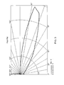
- Figure 3 provides a polar plot illustrating the light distribution of a LED in conjunction with a LED optic according to one embodiment of the present invention. As illustrated in Figure 3 , the light distribution is substantially horizontal having a maximum intensity at a vertical angle of 77.5 degrees.
- a LED in conjunction with a LED optic has a light distribution having a maximum intensity at a vertical angle up to 80 degrees or up to 75 degrees.
- a LED in conjunction with a LED optic has a light distribution having a maximum intensity at a vertical angle up to 70 degrees.
- the ability of an LED optic to increase the horizontal or substantially horizontal distribution of light emitted from a LED contributes to the ability of the luminaire light source assembly to provide a standard horizontal illuminance of at least 10 lux from the luminaire.
- Figure 4 illustrates an elevational view of an LED optic according to one embodiment of the present invention.
- the LED optic (400) comprises a base (402) and an optical structure (404).
- the base (402) of the LED optic (400) can couple to a surface of the gear tray or other structure when the LED optic (400) is disposed over a LED.
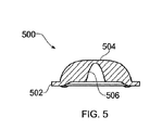
- Figure 5 illustrates a cross-sectional view of LED optic according to one embodiment of the present invention.
- the LED optic (500) comprises a base (502) and an optical structure (504).
- the optical structure (504) in the embodiment illustrated in Figure 5 demonstrates a variable thickness.
- the variable thickness of the optical structure (504) provides a cavity (506).
- LEDs and LED optics suitable for use in luminaire light source assemblies described herein are commercially available from Phillips Lumileds Lighting Company of San Jose, California under the LUXEON® Rebel product designation.
- LEDs suitable for use in luminaire light source assemblies of the present invention have a lifetime ofup to 50,000 hours, thereby reducing the frequency of underground luminaire maintenance resulting from expired light sources.
- LED optics of a luminaire light source assembly work in conjunction with one or more optics of an existing luminaire to provide a standard horizontal illuminance value recited herein.
- Figure 6 illustrates a cut away view of a luminaire light source assembly of the present invention interfaced with an existing luminaire (600) having an outer optic (602).
- an existing luminaire can comprise luminaires already installed and/or in use in underground lighting applications.
- the gear tray (100) provided in Figures 1 and 2 herein is disposed in the existing luminaire (600) and plugs into the power circuitry (not shown) of the luminaire for operation of the LEDs.
- the outer optic (602) in some embodiments, can work in conjunction with one or a plurality of LED optics of the light source assembly to provide a standard horizontal illuminance of at least 10 lux from the luminaire.
- At least one LED optic of a light source assembly and at least one optic, of a luminaire receiving the assembly work in conjunction to provide a LED light distribution from the luminaire having a maximum intensity at a vertical angle of up to about 80 degrees. In some embodiments, at least one LED optic of a light source assembly and at least one optic of a luminaire receiving the assembly work in conjunction to provide a LED light distribution from the luminaire having a maximum intensity at a vertical angle of up to about 75 degrees or up to about 70 degrees. In some embodiments, at least one LED optic and at least one optic of an existing luminaire work in conjunction to provide a LED light distribution from the luminaire having a maximum intensity at a vertical angle ranging from about 60 degrees to about 80 degrees.
- Figure 7 provides a polar plot illustrating the light distribution of a luminaire comprising a light source assembly according to one embodiment of the present invention.
- the plurality of LED optics of the light source assembly and the outer optic of the luminaire work together to provide a LED light distribution from the luminaire having a maximum intensity at a vertical angle ranging from about 60 degrees to about 80 degrees.
- the light distribution provided by the plurality of LED optics working in conjunction with one or more outer optics assist in achieving a standard horizontal illuminance of at least 10 lux from the luminaire.
- any design and/or configuration of a luminaire light source assembly comprising a gear tray, a plurality of LEDs and LED optics in conjunction with one or more optics of a luminaire operable to provide a standard horizontal illuminance value described herein are contemplated by the present invention.
- one or more outer optics of a luminaire comprise prismatic structures.
- LEDs and LED optics commercially available under the LUXEON® Rebel product designation are coupled to a gear tray in a linear array format as illustrated in Figures 1 and 2 herein.
- the gear tray is disposed in an existing METROLUXTM luminaire commercially available from Holophane Europe Limited of Buckinghamshire, England.
- the LED optics work in conjunction with the outer optic of the METROLUXTM luminaire to provide a standard horizontal illuminance value recited herein from the luminaire.
- the LED optics work in conjunction with the with the outer optic of the METROLUXTM luminaire to provide a standard horizontal illuminance of at least 5 lux or at least 10 lux from the luminaire.
- LEDs and LED optics commercially available under the LUXEON® Rebel product designation are coupled to a gear tray in a linear array format as illustrated in Figures 1 and 2 herein.
- the gear tray is disposed in an existing WIDERLIGHTTM luminaire commercially available from Holophane Europe Limited of Buckinghamshire, England.
- the LED optics work in conjunction with the outer optic of the WIDERLIGHTTM luminaire to provide a standard horizontal illuminance value recited herein from the luminaire.
- the LED optics work in conjunction with the with the outer optic of the WIDERLIGHTTM luminaire to provide a standard horizontal illuminance of at least 5 lux or at least 10 lux from the luminaire.
- the present invention provides a luminaire comprising a gear tray, a plurality of LEDs coupled to one or more surfaces of the gear tray, a plurality of inner LED optics and an outer optic, wherein the luminaire has a standard horizontal illuminance of at least 5 lux. In some embodiments, the luminaire has a standard horizontal illuminance of at least 10 lux. In some embodiments, the luminaire has a standard horizontal illuminance of at least 20 lux.
- the gear tray, LEDs and LED optics of the luminaire are consistent with any of the same described herein for the luminaire light source assembly.
- the outer optic of the luminaire comprises any design and/or configuration operable to work in conjunction with one or more LED optics to achieve a standard horizontal illuminance described herein.
- an outer optic comprises a plurality of prismatic surface structures.
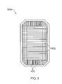
- Figure 8 illustrates a bottom plan view of an outer optic according to one embodiment of the present invention.
- the outer optic (800) of Figure 8 comprises surfaces comprising prismatic structures (802).
- an outer optic is commercially available from Holophane Europe Limited under the METROLUXTM and WIDERLlGHTTM product designations.
- an outer optic is constructed of any material not inconsistent with the objectives of the present invention.
- an outer optic of a luminaire is constructed of glass.
- glass comprises pressed borosilicate glass.
- the outer optic is constructed of a polymeric material.
- Figure 9 illustrates a luminaire according to one embodiment of the present invention.
- the luminaire (900) of Figure 9 comprises a gear tray comprising two bracket mounting surfaces (902, 904) for receiving a plurality of LEDs and LED optics (906) in a linear array format.
- the outer optic (908) of the luminaire works in conjunction with LED optics (906) to provide the luminaire a standard horizontal illuminance value described herein.
- luminaires of the present invention are suitable for use in underground lighting applications.
- luminaires are used in the lighting of underground transportation tunnels, including running tunnels, crossover and junction tunnels.
- Luminaires described herein can additionally find application in cable shafts, ventilation shafts, lift pits and shafts.
- a method of replacing a light source of luminaire in an underground lighting application comprises removing the light source from the luminaire architecture and interfacing a light source assembly with the luminaire architecture, the light source assembly comprising a gear tray, a plurality of LEDs coupled to one or more surfaces of the gear tray and a plurality of LED optics, wherein the light source assembly provides a standard horizontal illuminance of at least 5 lux from the luminaire.
- the light source assembly provides a standard horizontal illuminance of at least 10 lux from the luminaire.
- the light source assembly provides a standard horizontal illuminance of at least 20 lux from the luminaire.
- a luminaire light source replaced according to methods described herein comprises a incandescent light source or a fluorescent light source.
- the ability of a luminaire light source assembly to interface with an existing luminaire architecture permits the in-situ replacemant of light sources of luminaires used in underground lighting applications. As a result, less efficient, broken or damaged luminaire light sources can be replaced with LED light sources without having to remove the luminiare from its installed position in the underground application.
- the outer optic of a luminaire can be removed or opened to expose the light source to be replaced.
- the light source can be removed from the luminaire architecture, and a luminaire light source assembly comprising a gear tray, a plurality of LEDs and LED optics can be coupled to the luminaire architecture without any modifications of the luminaire architecture and/or conversion apparatus.
Landscapes
- Engineering & Computer Science (AREA)
- General Engineering & Computer Science (AREA)
- Architecture (AREA)
- Civil Engineering (AREA)
- Structural Engineering (AREA)
- Non-Portable Lighting Devices Or Systems Thereof (AREA)
- Arrangement Of Elements, Cooling, Sealing, Or The Like Of Lighting Devices (AREA)
- Fastening Of Light Sources Or Lamp Holders (AREA)
Abstract
Description
- The present application claims priority pursuant to 35 U.S.C. § 119(e) to United States Provisional Patent Application Serial No.
61/248,950. filed October 6, 2010 - The present invention relates to luminaire assemblies and, in particular, to luminaire assemblies operable to interface with existing luminaire infrastructure.
- Luminaires for providing general illumination to an area are well known and often used in outdoor lighting applications including roadway and sidewalk lighting, parking lot lighting, and residential area lighting. Luminaires also find use in underground applications, such as in the lighting of tunnels, shafts and platforms.
- Currently available luminaires incorporate various light sources including incandescent, fluorescent, halogen, high intensity discharge and light emitting diodes (LEDs). Incandescent light sources are highly inefficient due to significant amounts of energy dissipated as heat. Moreover, although more efficient than incandescent light sources, fluorescent lamps can suffer shorter lifetimes depending on operating environment factors.
- Comparatively, LED light sources offer several advantages including high lighting efficiency, long lifetimes, typically between 10,000 and 60,000 hours of operation, resistance to physical or mechanical shock and rapid lighting response time. Long lifetimes are an attractive property of LEDs for underground lighting applications. In underground transportation systems such as subways and train tunnels, for example, replacement of luminaire light sources is costly as replacement procedures often require closing of underground passageways. Closing passageways of underground transportation systems can potentially result in disruption of services and loss of revenue. As a result, long lifetime luminaire light sources are generally desirable.
- Nevertheless, LEDs exhibit several disadvantages which challenge their use in luminaire constructions, including luminaires used for underground lighting applications. The performance of an LED, for example, is largely dependent on the temperature of the operating environment. Operating an LED in high ambient temperatures can lead to overheating and device failure. Moreover, LEDs generally project a narrow field of light in comparison with other light sources. As a result it can be difficult to achieve sufficient illumination over a wide area with LED sources Furthermore, narrow field light projection can lead to glare capable of interfering with the sight of personnel operating machinery in an underground passageway and can climinate the stroboscopic effect associated with other light sources/control gear.
- In view of the foregoing, the present invention provides luminaires and luminaire light source assemblies incorporating LEDs. In some embodiments, luminaires and luminaire light source assemblies described herein can overcome disadvantages that have limited or precluded the use of LEDs in underground lighting applications.
- Moreover, in some embodiments, luminaires and luminaire light source assemblies of the invention are operable to interface with existing luminaire infrastructure and serve as replacement assemblies for less efficient, damaged or broken luminaires currently in use in underground lighting applications. The ability of luminaire light source assemblies described herein, for example to interface with existing luminaire infrastructure, in some embodiments, permits the in-situ replacement of light sources of less efficient, damaged or broken luminaires currently in use in underground lighting applications with higher efficiency and longer lifetime LEDs.
- In one embodiment, the present invention provides a luminaire light source assembly comprising a gear tray, a plurality of light emitting diodes (LEDs) coupled to one or more surfaces of the gear tray and a plurality of LED optics, wherein the light source assembly provides a standard horizontal illuminance of at least 5 lux from the luminaire in which it is positioned. In some embodiments, a luminaire light source assembly provides a standard horizontal illuminance of at least 10 lux from the luminaire. In some embodiments, a luminaire light source assembly provides a standard horizontal illuminance of at least 20 lux from the luminaire.
- In some embodiments, a luminaire light source assembly described herein comprising a plurality of LEDs and a plurality of LED optics can replace existing light sources of luminaires used in underground applications, including compact fluorescent light sources.
- Moreover, in some embodiments, a luminaire light source assembly further comprises one or more outer optics operable to work in conjunction with the plurality of LED optics to provide a standard horizontal illuminance of at least 10 lux from a luminaire. In some embodiments, the one or more outer optics is provided by the luminaire receiving the light source assembly. In other embodiments, a luminaire light source assembly comprises one or more outer optics independent of the luminaire receiving the assembly.
- In another aspect, the present invention provides a luminaire comprising a gear tray, a plurality of LEDs coupled to one or more surfaces of the gear tray, a plurality of inner LED optics and an outer optic, wherein the luminaire has a standard horizontal illuminance of at least 5 lux. In some embodiments, the luminaire has a standard horizontal luminance of at least 10 lux. In some embodiments, the luminaire has a standard horizontal luminance of at least 20 lux.
- The present invention, in another aspect, provides methods of replacing a light source of a luminaire. In one embodiment, a method of replacing a light source of a luminaire comprises removing the light source from the luminaire architecture and interfacing a light source assembly with the luminaire architecture, the light source assembly comprising a gear tray, a plurality of LEDs coupled to one or more surfaces of the gear tray and a plurality of LED optics, wherein the light source assembly provides a standard horizontal illuminance of at least 5 lux from the luminaire. In some embodiments, the luminaire is part of an underground lighting system, such as in underground transportation systems.
- In some embodiments, the ability of a luminaire light source assembly described herein to interface with a pre-existing luminaire architecture permits the in-situ replacement of light sources of luminaires used in underground lighting applications. As a result, less efficient, broken or damaged luminaire light sources can be replaced or retrofit with LED light sources without having to remove the luminiare from its installed position in the underground application.
-
-
Figure 1 illustrates an elevational view of a luminaire light source assembly according to one embodiment of the present invention. -
Figure 2 illustrates a perspective view of a luminaire light source assembly according to one embodiment of the present invention. -
Figure 3 provides a polar plot illustrating the light distribution of a LED in conjunction with a LED optic according to one embodiment of the present invention. -
Figure 4 illustrates an elevational view of a LED optic according to one embodiment of the present invention. -
Figure 5 illustrates a cross-sectional view of a LED optic according to one embodiment of the present invention. -
Figure 6 illustrates a cut away view of a luminaire according to one embodiment of the present invention. -
Figure 7 provides a polar plot illustrating the light distribution from a luminaire according to one embodiment of the present invention. -
Figure 8 illustrates a bottom plan view of an outer optic of a luminaire according to one embodiment of the present invention. -
Figure 9 illustrates an elevational view of a luminaire according to one embodiment of the present invention. -
Figure 10 illustrates a plan view of the back of a luminaire light source assembly according to one embodiment of the present invention. - the present invention can be understood more readily by reference to the following detailed description and drawings and their previous and following descriptions. Elements. apparatus and methods of the present invention, however, are not limited to the specific embodiments presented in the detailed description and drawings. It should be recognized that these embodiments are merely illustrative of the principles of the present invention. Numerous modifications and adaptations will be readily apparent to those of skill in the art without departing from the spirit and scope of the invention.
- The present invention provides luminaires and luminaire light source assemblies incorporating LEDs for use in various underground lighting applications. In some embodiments, luminaires and luminaire light source assemblies described herein can overcome disadvantages that have limited or precluded the use of LEDs in underground lighting applications.
- Moreover, in some embodiments, luminaires and luminaire light source assemblies of the invention are operable to interface with existing luminaire infrastructure and serve as replacement assemblies for less efficient, damaged or broken luminaires currently in use in underground lighting applications. The ability of luminaire light source assemblies described herein, for example, to interface with existing luminaire infrastructure, in some embodiments, permits the in-situ replacement of light sources of less efficient, damaged or broken luminaires currently in use in underground lighting applications with higher efficiency and longer lifetime LEDs.
- In one embodiment, the present invention provides a luminaire light source assembly comprising a gear tray, a plurality of LED coupled to one or more surfaces of the gear tray and a plurality of LED optics, wherein the light source assembly provides a standard horizontal illuminance of at least 5 lux from the luminaire. In some embodiments, a luminaire light source assembly provides a standard horizontal illuminance of at least 10 lux from the luminaire. In some embodiments, a luminaire light source assembly provides a standard horizontal illuminance of at least 20 lux from the luminaire. In some embodiments, a luminaire light source assembly provides a standard horizontal illuminance from the luminaire ranging from 10 lux to 50 lux or from 20 lux to about 40 lux. In some embodiments, a luminaire light source assembly provides a standard horizontal illuminance from the luminaire ranging from 15 lux to 30 lux.
- Standard horizontal illuminance, as used herein, refers to the luminous flux incident on a horizontal surface 1.4 to 1.8 meters below the luminaire and 1.0 to 1.5 meters in front of the luminaire as determined according to Lighting of London Underground Assets No. 2-01105-002, Issue No. A1, Issue date - April 2005.
- A luminaire light source assembly, in some embodiments, can have any desired number of LEDs to achieve the illuminance values recited herein. In some embodiments, a luminaire light source assembly comprises at least 5 LEDs. In some embodiments, a luminaire light source assembly comprises at least 7 LEDs. A luminaire light source assembly, in some embodiments, comprises at least 10 LEDs. In some embodiments, a luminaire light source assembly comprises 5 to 15 LEDs or 10 to 20 LEDs.
- In some embodiments, LEDs of a luminaire light source assembly are coupled to one or more surfaces of the gear tray. A luminaire light source assembly can have any arrangement of LEDs operable to provide a luminaire the standard horizontal illuminance values recited herein. In some embodiments, the plurality of LEDs are arranged in one or more arrays on the gear tray. In one embodiment, for example, the plurality of LEDs of a luminaire light source assembly are arranged on the gear tray in two linear arrays, each linear array comprising at least 5 LEDs. In another embodiment, the plurality of LEDs are arranged on the gear tray in two linear arrays, each linear array comprising at least 7 LEDs.
- Moreover, in some embodiments, the plurality of LEDs are arranged into one or more shapes on the gear tray including, but not limited to, circular, elliptical, triangular, square or rectangular or polygonal. In some embodiments, the plurality of LEDs demonstrate a random arrangement on the gear tray.
-
Figure 1 illustrates an elevational view of a luminaire light source assembly according to one embodiment of the present invention. As illustrated inFigure 1 , the gear tray (100) comprises two bracket mounting surfaces (102, 104) for receiving a plurality of LEDs (103) in a linear array format. In the embodiment illustrated inFigure 1 . the two bracket mounting surfaces (102. 104) are parallel or substantially parallel to a horizontal surface (not shown) to be illuminated by the luminaire light source assembly. As a result, the plurality of LEDs (103) coupled to the bracket mounting surfaces (102, 104) face the horizontal surfaces to be illuminated. Having the LEDs face one or more horizontal surfaces to be illuminated, such as floors of train running tunnels and platforms, can assist in reducing glare generated from the LEDs. In some embodiments, for example, luminaires comprising light source assemblies described herein are compliant with the provisions of EN 1838, Emergency Lighting. - The gear tray (100) further comprises heat sinks (106, 108) adjacent to the bracket mounting surfaces (102, 104). Heat sinks (105, 108) comprise a plurality of fins (110) that assist in maintaining the LEDs at an acceptabte operating temperature by dissipating heat generated by the LEDs. A gear tray can have any desired number of fins (110) for assisting in the dissipation or heat generated by operation of the LEDs. The fins (110) can have any desired shape or construction. In some embodiments, the this (110) are tapered. In some embodiments, the fins (110) are planar. In some embodiments, the fins (110) are curved. Moreover, in some embodiments, at least two of the fins (110) have unequal heights. In some embodiments, the fins (110) have the same or substantially the same height.
- The gear tray (100) additionally comprises plug circuitry (105) for interfacing with existing luminaire power infrastructure. In some embodiments, for example, the gear tray (100) can simply plug into circuitry of a power source used by a light source being replaced.
- Moreover, the gear tray (100) is coupled to LED driver circuitry (112) for operation of the LFDs coupled to the bracket mounting surfaces (102, 104). Any LED driver circuitry not inconsistent with the objectives of the present invention can be used. In some embodiments, for example, the LED driver circuitry is compliant with one or more electromagnetic compatibility (EMC) requirements of an underground transportation system, including the EMC requirements of the London Underground. In some embodiments, suitable LED driver circuitry is commercially available from Harvard Engineering PLC of Leeds, England.
- In some embodiments, the LED is disposed in a metal casing- Additionally, in some embodiments, the LED driver circuitry provides an output current of about 450 mA. The LED driver circuitry, in some embodiments, comprises architecture resistant to various voltage surges.
-
Figure 2 illustrates a perspective view of the gear tray (100) ofFigure 1 . In the embodiment displayed inFigure 2 , the plurality of fins (110) of heat sinks (106, 108) are commensurate with the width of the gear tray to maximize surface area for heat dissipation. In other embodiments, however, fins of heat sinks or other structures do not span the width of the gear tray. Additionally, an inclined plane (116) is disposed between LED bracket mounting surfaces (102, 104), the bracket mounting surfaces (102, 104) each comprising a one-dimensional array oF LEDs (103). The inclined plane (116) assists in accommodating the fins (110) of heat sink (108) while maintaining the monolithic structure of the gear tray (100). The inclined plane, in some embodiments, does not affect or substantially affect the light distribution of the luminaire light source assembly. In some embodiments, the inclined plane can assist in altering the light distribution form the luminaire light source assembly. -
Figure 10 illustrates a plan view of the back of the luminaire light source assembly ofFigure 1 . As illustrated inFigure 10 , the gear tray (100) of the luminaire light assembly comprises plug circuitry (105) for interfacing with existing luminaire power infrastructure. In some embodiments, for example, the gear tray (100) can plug into circuitry of a power source used by a light source being replaced. Moreover, the gear tray (100) is coupled to LED driver circuitry (112) for operation of the LEDs. - A gear tray of a luminaire light source assembly can be constructed of any material not inconsistent with the objectives of the present invention. In some embodiment, a gear tray is constructed of a polymeric material. In some embodiments, a gear tray is constructed of a fiber reinforced polymeric material, including glass fiber reinforced polymeric materials. Luminaire light source assemblies and luminaires of the present invention, in some embodiments, are compliant with the provisions of the United Kingdom Fire Precautions (Sub-surface Railway Station) Regulations of 1989 introduced under
Section 12 of the Fire Precautions Act of 1971. - As provided herein, a luminaire light source assembly also comprises a plurality LED optics. In some embodiments, the plurality of LED optics work in conjunction with one or more optics of an existing luminaire to provide a standard horizontal illuminance described herein from the luminaire. In one embodiment, for example, the plurality of LED optics work in conjunction with a single outer optic of an existing luminaire to provide a standard horizontal illuminance of at least 10 lux from the luminaire. Existing luminaires, in some embodiments, comprise luminaires already installed and/or in use in underground lighting applications.
- In some embodiments, an individual LED optic is associated with each of the plurality of LEDs coupled to one or more surfaces of the gear tray. In one embodiment, for example, a LED optic is disposed over each LED of the gear tray. In some embodiments, a LED optic is coupled to the gear tray over a LED. A LED optic can be snapped into place over a LED or coupled to the gear tray by some other form of mechanical engagement. In other embodiments, a LED optic is chemically adhered or bonded to the gear tray over a LED.
- LED optics, in some embodiments, can increase the horizontal or substantially horizontal distribution of light emitted from a LED.
Figure 3 provides a polar plot illustrating the light distribution of a LED in conjunction with a LED optic according to one embodiment of the present invention. As illustrated inFigure 3 , the light distribution is substantially horizontal having a maximum intensity at a vertical angle of 77.5 degrees. In some embodiments, a LED in conjunction with a LED optic has a light distribution having a maximum intensity at a vertical angle up to 80 degrees or up to 75 degrees. In some embodiments, a LED in conjunction with a LED optic has a light distribution having a maximum intensity at a vertical angle up to 70 degrees. - The ability of an LED optic to increase the horizontal or substantially horizontal distribution of light emitted from a LED, in some embodiments, contributes to the ability of the luminaire light source assembly to provide a standard horizontal illuminance of at least 10 lux from the luminaire.
-
Figure 4 illustrates an elevational view of an LED optic according to one embodiment of the present invention. The LED optic (400) comprises a base (402) and an optical structure (404). The base (402) of the LED optic (400) can couple to a surface of the gear tray or other structure when the LED optic (400) is disposed over a LED. Moreover,Figure 5 illustrates a cross-sectional view of LED optic according to one embodiment of the present invention. The LED optic (500) comprises a base (502) and an optical structure (504). The optical structure (504) in the embodiment illustrated inFigure 5 demonstrates a variable thickness. The variable thickness of the optical structure (504) provides a cavity (506). - LEDs and LED optics suitable for use in luminaire light source assemblies described herein, in some embodiments, are commercially available from Phillips Lumileds Lighting Company of San Jose, California under the LUXEON® Rebel product designation. In some embodiments, LEDs suitable for use in luminaire light source assemblies of the present invention have a lifetime ofup to 50,000 hours, thereby reducing the frequency of underground luminaire maintenance resulting from expired light sources.
- As provided herein, LED optics of a luminaire light source assembly, in some embodiments, work in conjunction with one or more optics of an existing luminaire to provide a standard horizontal illuminance value recited herein.
-
Figure 6 illustrates a cut away view of a luminaire light source assembly of the present invention interfaced with an existing luminaire (600) having an outer optic (602). As described herein, an existing luminaire can comprise luminaires already installed and/or in use in underground lighting applications. The gear tray (100) provided inFigures 1 and2 herein is disposed in the existing luminaire (600) and plugs into the power circuitry (not shown) of the luminaire for operation of the LEDs. The outer optic (602), in some embodiments, can work in conjunction with one or a plurality of LED optics of the light source assembly to provide a standard horizontal illuminance of at least 10 lux from the luminaire. - In some embodiments, at least one LED optic of a light source assembly and at least one optic, of a luminaire receiving the assembly work in conjunction to provide a LED light distribution from the luminaire having a maximum intensity at a vertical angle of up to about 80 degrees. In some embodiments, at least one LED optic of a light source assembly and at least one optic of a luminaire receiving the assembly work in conjunction to provide a LED light distribution from the luminaire having a maximum intensity at a vertical angle of up to about 75 degrees or up to about 70 degrees. In some embodiments, at least one LED optic and at least one optic of an existing luminaire work in conjunction to provide a LED light distribution from the luminaire having a maximum intensity at a vertical angle ranging from about 60 degrees to about 80 degrees.
-
Figure 7 provides a polar plot illustrating the light distribution of a luminaire comprising a light source assembly according to one embodiment of the present invention. As demonstrated inFigure 7 . the plurality of LED optics of the light source assembly and the outer optic of the luminaire work together to provide a LED light distribution from the luminaire having a maximum intensity at a vertical angle ranging from about 60 degrees to about 80 degrees. - In some embodiments described herein, the light distribution provided by the plurality of LED optics working in conjunction with one or more outer optics assist in achieving a standard horizontal illuminance of at least 10 lux from the luminaire.
- Any design and/or configuration of a luminaire light source assembly comprising a gear tray, a plurality of LEDs and LED optics in conjunction with one or more optics of a luminaire operable to provide a standard horizontal illuminance value described herein are contemplated by the present invention. In some embodiments one or more outer optics of a luminaire comprise prismatic structures.
- In one embodiment, for example, LEDs and LED optics commercially available under the LUXEON® Rebel product designation are coupled to a gear tray in a linear array format as illustrated in
Figures 1 and2 herein. The gear tray is disposed in an existing METROLUX™ luminaire commercially available from Holophane Europe Limited of Buckinghamshire, England. The LED optics work in conjunction with the outer optic of the METROLUX™ luminaire to provide a standard horizontal illuminance value recited herein from the luminaire. In some embodiments, for example, the LED optics work in conjunction with the with the outer optic of the METROLUX™ luminaire to provide a standard horizontal illuminance of at least 5 lux or at least 10 lux from the luminaire. - In another embodiment, for example, LEDs and LED optics commercially available under the LUXEON® Rebel product designation are coupled to a gear tray in a linear array format as illustrated in
Figures 1 and2 herein. The gear tray is disposed in an existing WIDERLIGHT™ luminaire commercially available from Holophane Europe Limited of Buckinghamshire, England. The LED optics work in conjunction with the outer optic of the WIDERLIGHT™ luminaire to provide a standard horizontal illuminance value recited herein from the luminaire. In some embodiments, the LED optics work in conjunction with the with the outer optic of the WIDERLIGHT™ luminaire to provide a standard horizontal illuminance of at least 5 lux or at least 10 lux from the luminaire. - In another aspect, the present invention provides a luminaire comprising a gear tray, a plurality of LEDs coupled to one or more surfaces of the gear tray, a plurality of inner LED optics and an outer optic, wherein the luminaire has a standard horizontal illuminance of at least 5 lux. In some embodiments, the luminaire has a standard horizontal illuminance of at least 10 lux. In some embodiments, the luminaire has a standard horizontal illuminance of at least 20 lux.
- In some embodiments, the gear tray, LEDs and LED optics of the luminaire are consistent with any of the same described herein for the luminaire light source assembly.
- Moreover, the outer optic of the luminaire, in some embodiments, comprises any design and/or configuration operable to work in conjunction with one or more LED optics to achieve a standard horizontal illuminance described herein. In some embodiments, an outer optic comprises a plurality of prismatic surface structures.
-
Figure 8 illustrates a bottom plan view of an outer optic according to one embodiment of the present invention. The outer optic (800) ofFigure 8 comprises surfaces comprising prismatic structures (802). In some embodiments, an outer optic is commercially available from Holophane Europe Limited under the METROLUX™ and WIDERLlGHT™ product designations. - In some embodiments, an outer optic is constructed of any material not inconsistent with the objectives of the present invention. In some embodiments, an outer optic of a luminaire is constructed of glass. In some embodiments, glass comprises pressed borosilicate glass. In other embodiments, the outer optic is constructed of a polymeric material.
-
Figure 9 illustrates a luminaire according to one embodiment of the present invention. The luminaire (900) ofFigure 9 comprises a gear tray comprising two bracket mounting surfaces (902, 904) for receiving a plurality of LEDs and LED optics (906) in a linear array format. The outer optic (908) of the luminaire works in conjunction with LED optics (906) to provide the luminaire a standard horizontal illuminance value described herein. - As provided herein, luminaires of the present invention are suitable for use in underground lighting applications. In some embodiments, luminaires are used in the lighting of underground transportation tunnels, including running tunnels, crossover and junction tunnels. Luminaires described herein can additionally find application in cable shafts, ventilation shafts, lift pits and shafts.
- The present invention, in another aspect, provides methods of replacing a light source of a luminaire in an underground lighting application. In one embodiment, a method of replacing a light source of luminaire in an underground lighting application comprises removing the light source from the luminaire architecture and interfacing a light source assembly with the luminaire architecture, the light source assembly comprising a gear tray, a plurality of LEDs coupled to one or more surfaces of the gear tray and a plurality of LED optics, wherein the light source assembly provides a standard horizontal illuminance of at least 5 lux from the luminaire. In some embodiments, the light source assembly provides a standard horizontal illuminance of at least 10 lux from the luminaire. In some embodiments, the light source assembly provides a standard horizontal illuminance of at least 20 lux from the luminaire.
- In some; embodiments, a luminaire light source replaced according to methods described herein comprises a incandescent light source or a fluorescent light source.
- In some embodiments, the ability of a luminaire light source assembly to interface with an existing luminaire architecture permits the in-situ replacemant of light sources of luminaires used in underground lighting applications. As a result, less efficient, broken or damaged luminaire light sources can be replaced with LED light sources without having to remove the luminiare from its installed position in the underground application. In some embodiments, for example, the outer optic of a luminaire can be removed or opened to expose the light source to be replaced. The light source can be removed from the luminaire architecture, and a luminaire light source assembly comprising a gear tray, a plurality of LEDs and LED optics can be coupled to the luminaire architecture without any modifications of the luminaire architecture and/or conversion apparatus.
- It is to be understood that the present description illustrates aspects of the invention relevant to a clear understanding of the invention. Certain aspects of the invention that would be apparent to those of ordinary skill in the art and that, therefore, would not facilitate a better understanding of the invention have not been presented in order to simplify the present description. Although the present invention has been described in connection with certain embodiments, the present invention is not limited to the particular embodiments disclosed, but is intended to cover modifications that are within the spirit and scope of the invention.
- Embodiments of the invention will nowbe described in the following paragraphs:
- 1. A luminaire light source assembly comprising:
- a gear tray;
- a plurality of light emitting diodes (LED) coupled to one or more surfaces of the gear tray: and
- a plurality of LED optics, wherein the light source assembly provides a standard horizontal illuminance of at least 5 lux from the luminaire.
- 2. The luminaire light source assembly of paragraph 1, wherein the light source assembly provides a standard horizontal illuminance of at least about 10 lux from the luminaire.
- 3. The luminaire light source assembly of paragraph 1, wherein the LEDs arc coupled to a surface of the gear tray substantially parallel to a horizontal surface illuminated by the luminaire light source assembly.
- 4. The luminaire light source assembly of paragraph 1, wherein a LED in conjunction with a LED optic has a light distribution having a maximum intensity at a vertical angle less than 80 degrees.
- 5. The luminaire light source assembly of paragraph 1, wherein a LED in conjunction with a LED optic has a light distribution having a maximum intensity at a vertical angle less than 75 degrees.
- 6. The luminaire light source assembly of paragraph 1 further comprising LED driver circuitry coupled to the gear tray.
- 7. The luminaire light source assembly of paragraph 1 further comprising plug circuitry.
- 8. A luminaire comprising:
- a luminaire light source assembly comprising a gear tray, a plurality of light emitting diodes (LED) coupled to one or more surfaces of the gear tray and a plurality of LED optics; and
- an outer optic,
- 9. The luminaire of
paragraph 8. wherein the LEDs are coupled to a surface of the gear tray substantially parallel to a horizontal surface illuminated by the luminaire light source assembly. - 10. The luminaire of
paragraph 8, wherein the luminaire has a light distribution having a maximum intensity at a vertical angle up to about 80 degrees. - 11. The luminaire of
paragraph 8, wherein the luminaire has a light distribution having a maximum intensity at a vertical angle ranging from 60 degrees to 80 degrees. - 12. The luminaire of
paragraph 8, wherein the luminaire light source assembly is a replacement light source for the luminaire. - 13. The luminaire of
paragraph 12, wherein the luminaire is part of an underground lighting system. - 14. A method of replacing a light source of a luminaire comprising
- removing the light source from the luminaire architecture;
- interfacing a light source assembly with the luminaire architecture, the light source assembly comprising a gear tray, a plurality of LEDs coupled to one or more surfaces of the gear tray and a plurality of LED optics, wherein the light source assembly provides a standard horizontal illuminance of at least 5 lux from the luminaire.
- 15. The method of
paragraph 14, wherein the luminaire is part of a underground lighting system. - It should be understood that various changes and modifications to the presently preferred embodiments described herein will be apparent to those skilled in the art. Such changes and modifications can be made without departing from the spirit and scope of the present invention and without diminishing its intended advantages. It is therefore intended that such changes and modifications be covered by the following claims.
Claims (15)
- A luminaire light source assembly comprising:a gear tray;a plurality of light emitting diodes (LED) coupled to one or more surfaces of the gear tray; anda plurality of LED optics, wherein the light source assembly provides a standard horizontal illuminance of at least 5 lux from the luminaire.
- The luminaire light source assembly of claim 1, wherein the light source assembly provides a standard horizontal illuminance of at least about 10 lux from the luminaire.
- The luminaire light source assembly of claim 1, wherein the LEDs are coupled to a surface of the gear tray substantially parallel to a horizontal surface illuminated by the luminaire light source assembly.
- The luminaire light source assembly of claim 1, wherein a LED in conjunction with a LED optic has a light distribution having a maximum intensity at a vertical angle less than 80 degrees.
- The luminaire light source assembly of claim 1, wherein a LED in conjunction with a LED optic has a light distribution having a maximum intensity at a vertical angle less than 75 degrees.
- The luminaire light source assembly of claim 1 further comprising LED driver circuitry coupled to the gear tray.
- The luminaire light source assembly of claim 1 further comprising plug circuitry.
- A luminaire comprising the luminaire light source assembly of claim 1 and an outer optic.
- The luminaire of claim 8, wherein the LEDs are coupled to a surface of the gear tray substantially parallel to a horizontal surface illuminated by the luminaire light source assembly.
- The luminaire of claim 8, wherein the luminaire has a light distribution having a maximum intensity at a vertical angle up to about 80 degrees.
- The luminaire of claim 8, wherein the luminaire has a light distribution having a maximum intensity at a vertical angle ranging from 60 degrees to 80 degrees.
- The luminaire of claim 8, wherein the luminaire light source assembly is a replacement light source for the luminaire.
- The luminaire of claim 12, wherein the luminaire is part of an underground lighting system.
- A method of replacing a light source of a luminaire comprising:removing the light source from the luminaire architecture;interfacing a light source assembly with the luminaire architecture, the light source assembly comprising a gear tray, a plurality of LEDs coupled to one or more surfaces of the gear tray and a plurality of LED optics, wherein the light source assembly provides a standard horizontal illuminance of at least 5 lux from the luminaire.
- The method of claim 14, wherein the luminaire is part of a underground lighting system.
Applications Claiming Priority (1)
| Application Number | Priority Date | Filing Date | Title |
|---|---|---|---|
| US24895009P | 2009-10-06 | 2009-10-06 |
Publications (3)
| Publication Number | Publication Date |
|---|---|
| EP2309171A2 true EP2309171A2 (en) | 2011-04-13 |
| EP2309171A3 EP2309171A3 (en) | 2013-12-18 |
| EP2309171B1 EP2309171B1 (en) | 2016-05-18 |
Family
ID=43500390
Family Applications (1)
| Application Number | Title | Priority Date | Filing Date |
|---|---|---|---|
| EP10251752.1A Active EP2309171B1 (en) | 2009-10-06 | 2010-10-06 | Luminaire assemblies and applications thereof |
Country Status (2)
| Country | Link |
|---|---|
| US (1) | US8408740B2 (en) |
| EP (1) | EP2309171B1 (en) |
Cited By (2)
| Publication number | Priority date | Publication date | Assignee | Title |
|---|---|---|---|---|
| US8408740B2 (en) | 2009-10-06 | 2013-04-02 | Abl Ip Holding Llc | Luminaire assemblies and applications thereof |
| EP2745047A4 (en) * | 2011-08-17 | 2015-09-23 | Atlas Lighting Products Inc | LED LIGHT |
Families Citing this family (16)
| Publication number | Priority date | Publication date | Assignee | Title |
|---|---|---|---|---|
| US20110031887A1 (en) * | 2009-05-28 | 2011-02-10 | Stoll Arnold | Led lighting system |
| US8610357B2 (en) | 2009-05-28 | 2013-12-17 | Zon Led, Llc | LED assembly for a signage illumination |
| US8098433B2 (en) * | 2009-12-11 | 2012-01-17 | Solatube International, Inc. | Direct and indirect light diffusing devices and methods |
| US8568011B2 (en) | 2009-08-20 | 2013-10-29 | Solatube International, Inc. | Daylighting devices with auxiliary lighting system and light turning features |
| DE102010001255A1 (en) * | 2010-01-27 | 2011-07-28 | Osram Gesellschaft mit beschränkter Haftung, 81543 | light assembly |
| US8601757B2 (en) | 2010-05-27 | 2013-12-10 | Solatube International, Inc. | Thermally insulating fenestration devices and methods |
| US8837048B2 (en) | 2011-11-30 | 2014-09-16 | Solatube International, Inc. | Daylight collection systems and methods |
| US9921397B2 (en) | 2012-12-11 | 2018-03-20 | Solatube International, Inc. | Daylight collectors with thermal control |
| US8982467B2 (en) | 2012-12-11 | 2015-03-17 | Solatube International, Inc. | High aspect ratio daylight collectors |
| US9816675B2 (en) | 2015-03-18 | 2017-11-14 | Solatube International, Inc. | Daylight collectors with diffuse and direct light collection |
| CA2980037C (en) | 2015-03-18 | 2018-08-28 | Solatube International, Inc. | Daylight collectors with diffuse and direct light collection |
| FR3041004B1 (en) * | 2015-09-10 | 2020-08-28 | Normalu | SLAB FRAME DISTRIBUTING AN EXTERNAL PERIPHERAL LIGHT AND SLAB INCLUDING SUCH A FRAME |
| US10386058B1 (en) * | 2016-03-17 | 2019-08-20 | Shat-R-Shield, Inc. | LED luminaire |
| US10767849B2 (en) | 2016-04-25 | 2020-09-08 | Shat-R-Shield, Inc. | LED luminaire |
| EP3647656A1 (en) | 2018-10-29 | 2020-05-06 | Eaton Intelligent Power Limited | Wallpack light fixture |
| USD905323S1 (en) | 2018-10-29 | 2020-12-15 | Eaton Intelligent Power Limited | Wallpack light fixture |
Family Cites Families (9)
| Publication number | Priority date | Publication date | Assignee | Title |
|---|---|---|---|---|
| KR20030044324A (en) * | 2001-11-29 | 2003-06-09 | (주)네오정보시스템 | Lamp for tunnel with light emitting diode |
| US20060146531A1 (en) * | 2004-12-30 | 2006-07-06 | Ann Reo | Linear lighting apparatus with improved heat dissipation |
| EP1922227A4 (en) * | 2005-09-06 | 2011-03-02 | Lsi Industries Inc | Linear lighting system |
| CN100578077C (en) * | 2007-07-30 | 2010-01-06 | 深圳市邦贝尔电子有限公司 | Led tunnel lamp |
| DE102007043904A1 (en) * | 2007-09-14 | 2009-03-19 | Osram Gesellschaft mit beschränkter Haftung | Luminous device |
| CN201215265Y (en) * | 2008-06-06 | 2009-04-01 | 哈尔滨市电子计算技术研究所 | Non-horizontal irradiation anti-dazzle LED tunnel lamp |
| CN201265809Y (en) * | 2008-10-11 | 2009-07-01 | 杭州恩迪照明科技有限公司 | LED tunnel illumination device |
| CA2745396A1 (en) * | 2008-12-03 | 2010-06-10 | Illumination Management Solutions, Inc. | An led replacement lamp and a method of replacing preexisting luminaires with led lighting assemblies |
| EP2309171B1 (en) | 2009-10-06 | 2016-05-18 | ABL IP Holding, LLC | Luminaire assemblies and applications thereof |
-
2010
- 2010-10-06 EP EP10251752.1A patent/EP2309171B1/en active Active
- 2010-10-06 US US12/899,174 patent/US8408740B2/en active Active
Cited By (3)
| Publication number | Priority date | Publication date | Assignee | Title |
|---|---|---|---|---|
| US8408740B2 (en) | 2009-10-06 | 2013-04-02 | Abl Ip Holding Llc | Luminaire assemblies and applications thereof |
| EP2745047A4 (en) * | 2011-08-17 | 2015-09-23 | Atlas Lighting Products Inc | LED LIGHT |
| US9482395B2 (en) | 2011-08-17 | 2016-11-01 | Atlas Lighting Products, Inc. | LED luminaire |
Also Published As
| Publication number | Publication date |
|---|---|
| EP2309171B1 (en) | 2016-05-18 |
| US8408740B2 (en) | 2013-04-02 |
| EP2309171A3 (en) | 2013-12-18 |
| US20110110086A1 (en) | 2011-05-12 |
Similar Documents
| Publication | Publication Date | Title |
|---|---|---|
| US8408740B2 (en) | Luminaire assemblies and applications thereof | |
| US8789966B2 (en) | LED lighting assembly for fluorescent light fixtures | |
| EP2095014B1 (en) | Light engine assemblies | |
| US8304970B2 (en) | Light unit with induced convection heat sink | |
| EP2084452B1 (en) | Lighting assemblies and components for lighting assemblies | |
| US8083373B2 (en) | LED retrofit for fluorescent backlit signs | |
| US8827507B2 (en) | Lighting assemblies, methods of installing same, and methods of replacing lights | |
| US20160033088A1 (en) | Led light module and method for installing same | |
| EP2025998A1 (en) | Cooling structure for street lamp using light emitting diode | |
| US9353916B2 (en) | Elongated LED luminaire and associated methods | |
| US20110110085A1 (en) | Light Emitting Diode Module | |
| US8992040B2 (en) | LED beacon obstruction lighting system | |
| US10636950B2 (en) | Lighting device and method of making lighting device | |
| US9851054B2 (en) | Universal lamp support | |
| CN201954332U (en) | LED energy-saving lamp | |
| US10253965B2 (en) | Heated lens lighting arrangement with optic cable extending from light source to an opening in heat exchanger | |
| US9726336B2 (en) | LED lighting system, lamp retrofit system, kit, and method | |
| US20160356482A1 (en) | Canopy light system | |
| US8960951B1 (en) | LED lamp retrofit system, kit, and method | |
| US8262258B2 (en) | System for retrofitting an existing light fixture with an LED luminaire | |
| CN102644858A (en) | Light-emitting diode (LED) energy-saving bulb | |
| US10436432B2 (en) | Aluminum high bay light fixture having plurality of housings dissipating heat from light emitting elements | |
| WO2011001329A1 (en) | Led luminaire using louvers as a heat sink | |
| EP2066963B1 (en) | Lighting device | |
| KR20110113698A (en) | Lighting device |
Legal Events
| Date | Code | Title | Description |
|---|---|---|---|
| PUAI | Public reference made under article 153(3) epc to a published international application that has entered the european phase |
Free format text: ORIGINAL CODE: 0009012 |
|
| 17P | Request for examination filed |
Effective date: 20101021 |
|
| AK | Designated contracting states |
Kind code of ref document: A2 Designated state(s): AL AT BE BG CH CY CZ DE DK EE ES FI FR GB GR HR HU IE IS IT LI LT LU LV MC MK MT NL NO PL PT RO RS SE SI SK SM TR |
|
| AX | Request for extension of the european patent |
Extension state: BA ME |
|
| RIN1 | Information on inventor provided before grant (corrected) |
Inventor name: BARNWELL, DAVID Inventor name: JAVES, DAVID |
|
| PUAL | Search report despatched |
Free format text: ORIGINAL CODE: 0009013 |
|
| AK | Designated contracting states |
Kind code of ref document: A3 Designated state(s): AL AT BE BG CH CY CZ DE DK EE ES FI FR GB GR HR HU IE IS IT LI LT LU LV MC MK MT NL NO PL PT RO RS SE SI SK SM TR |
|
| AX | Request for extension of the european patent |
Extension state: BA ME |
|
| RIC1 | Information provided on ipc code assigned before grant |
Ipc: F21V 33/00 20060101ALI20131112BHEP Ipc: F21W 131/103 20060101ALN20131112BHEP Ipc: F21W 131/101 20060101ALN20131112BHEP Ipc: F21S 8/00 20060101ALI20131112BHEP Ipc: F21Y 101/02 20060101ALN20131112BHEP Ipc: F21S 8/08 20060101AFI20131112BHEP |
|
| 17Q | First examination report despatched |
Effective date: 20140526 |
|
| RIC1 | Information provided on ipc code assigned before grant |
Ipc: F21Y 101/02 20060101ALN20151007BHEP Ipc: F21W 131/103 20060101ALN20151007BHEP Ipc: F21W 131/101 20060101ALN20151007BHEP Ipc: F21S 8/08 20060101AFI20151007BHEP Ipc: F21V 33/00 20060101ALI20151007BHEP Ipc: F21S 8/00 20060101ALI20151007BHEP |
|
| GRAP | Despatch of communication of intention to grant a patent |
Free format text: ORIGINAL CODE: EPIDOSNIGR1 |
|
| RIC1 | Information provided on ipc code assigned before grant |
Ipc: F21Y 101/02 20060101ALN20151117BHEP Ipc: F21V 33/00 20060101ALI20151117BHEP Ipc: F21S 8/08 20060101AFI20151117BHEP Ipc: F21W 131/101 20060101ALN20151117BHEP Ipc: F21S 8/00 20060101ALI20151117BHEP Ipc: F21W 131/103 20060101ALN20151117BHEP |
|
| INTG | Intention to grant announced |
Effective date: 20151204 |
|
| RIC1 | Information provided on ipc code assigned before grant |
Ipc: F21V 33/00 20060101ALI20151126BHEP Ipc: F21S 8/08 20060101AFI20151126BHEP Ipc: F21S 8/00 20060101ALI20151126BHEP Ipc: F21W 131/103 20060101ALN20151126BHEP Ipc: F21Y 101/02 20060101ALN20151126BHEP Ipc: F21W 131/101 20060101ALN20151126BHEP |
|
| GRAS | Grant fee paid |
Free format text: ORIGINAL CODE: EPIDOSNIGR3 |
|
| GRAA | (expected) grant |
Free format text: ORIGINAL CODE: 0009210 |
|
| AK | Designated contracting states |
Kind code of ref document: B1 Designated state(s): AL AT BE BG CH CY CZ DE DK EE ES FI FR GB GR HR HU IE IS IT LI LT LU LV MC MK MT NL NO PL PT RO RS SE SI SK SM TR |
|
| REG | Reference to a national code |
Ref country code: GB Ref legal event code: FG4D |
|
| RIC1 | Information provided on ipc code assigned before grant |
Ipc: F21S 8/08 20060101AFI20160413BHEP Ipc: F21Y 101/00 20160101ALN20160413BHEP Ipc: F21W 131/103 20060101ALN20160413BHEP Ipc: F21V 33/00 20060101ALI20160413BHEP Ipc: F21S 8/00 20060101ALI20160413BHEP Ipc: F21W 131/101 20060101ALN20160413BHEP |
|
| REG | Reference to a national code |
Ref country code: CH Ref legal event code: EP |
|
| REG | Reference to a national code |
Ref country code: IE Ref legal event code: FG4D Ref country code: AT Ref legal event code: REF Ref document number: 800814 Country of ref document: AT Kind code of ref document: T Effective date: 20160615 |
|
| REG | Reference to a national code |
Ref country code: DE Ref legal event code: R096 Ref document number: 602010033440 Country of ref document: DE |
|
| REG | Reference to a national code |
Ref country code: NL Ref legal event code: MP Effective date: 20160518 |
|
| REG | Reference to a national code |
Ref country code: LT Ref legal event code: MG4D |
|
| PG25 | Lapsed in a contracting state [announced via postgrant information from national office to epo] |
Ref country code: NO Free format text: LAPSE BECAUSE OF FAILURE TO SUBMIT A TRANSLATION OF THE DESCRIPTION OR TO PAY THE FEE WITHIN THE PRESCRIBED TIME-LIMIT Effective date: 20160818 Ref country code: LT Free format text: LAPSE BECAUSE OF FAILURE TO SUBMIT A TRANSLATION OF THE DESCRIPTION OR TO PAY THE FEE WITHIN THE PRESCRIBED TIME-LIMIT Effective date: 20160518 Ref country code: NL Free format text: LAPSE BECAUSE OF FAILURE TO SUBMIT A TRANSLATION OF THE DESCRIPTION OR TO PAY THE FEE WITHIN THE PRESCRIBED TIME-LIMIT Effective date: 20160518 Ref country code: FI Free format text: LAPSE BECAUSE OF FAILURE TO SUBMIT A TRANSLATION OF THE DESCRIPTION OR TO PAY THE FEE WITHIN THE PRESCRIBED TIME-LIMIT Effective date: 20160518 |
|
| REG | Reference to a national code |
Ref country code: AT Ref legal event code: MK05 Ref document number: 800814 Country of ref document: AT Kind code of ref document: T Effective date: 20160518 |
|
| PG25 | Lapsed in a contracting state [announced via postgrant information from national office to epo] |
Ref country code: GR Free format text: LAPSE BECAUSE OF FAILURE TO SUBMIT A TRANSLATION OF THE DESCRIPTION OR TO PAY THE FEE WITHIN THE PRESCRIBED TIME-LIMIT Effective date: 20160819 Ref country code: PT Free format text: LAPSE BECAUSE OF FAILURE TO SUBMIT A TRANSLATION OF THE DESCRIPTION OR TO PAY THE FEE WITHIN THE PRESCRIBED TIME-LIMIT Effective date: 20160919 Ref country code: SE Free format text: LAPSE BECAUSE OF FAILURE TO SUBMIT A TRANSLATION OF THE DESCRIPTION OR TO PAY THE FEE WITHIN THE PRESCRIBED TIME-LIMIT Effective date: 20160518 Ref country code: RS Free format text: LAPSE BECAUSE OF FAILURE TO SUBMIT A TRANSLATION OF THE DESCRIPTION OR TO PAY THE FEE WITHIN THE PRESCRIBED TIME-LIMIT Effective date: 20160518 Ref country code: LV Free format text: LAPSE BECAUSE OF FAILURE TO SUBMIT A TRANSLATION OF THE DESCRIPTION OR TO PAY THE FEE WITHIN THE PRESCRIBED TIME-LIMIT Effective date: 20160518 Ref country code: HR Free format text: LAPSE BECAUSE OF FAILURE TO SUBMIT A TRANSLATION OF THE DESCRIPTION OR TO PAY THE FEE WITHIN THE PRESCRIBED TIME-LIMIT Effective date: 20160518 Ref country code: ES Free format text: LAPSE BECAUSE OF FAILURE TO SUBMIT A TRANSLATION OF THE DESCRIPTION OR TO PAY THE FEE WITHIN THE PRESCRIBED TIME-LIMIT Effective date: 20160518 |
|
| RAP2 | Party data changed (patent owner data changed or rights of a patent transferred) |
Owner name: ABL IP HOLDING LLC |
|
| PG25 | Lapsed in a contracting state [announced via postgrant information from national office to epo] |
Ref country code: IT Free format text: LAPSE BECAUSE OF FAILURE TO SUBMIT A TRANSLATION OF THE DESCRIPTION OR TO PAY THE FEE WITHIN THE PRESCRIBED TIME-LIMIT Effective date: 20160518 |
|
| PG25 | Lapsed in a contracting state [announced via postgrant information from national office to epo] |
Ref country code: DK Free format text: LAPSE BECAUSE OF FAILURE TO SUBMIT A TRANSLATION OF THE DESCRIPTION OR TO PAY THE FEE WITHIN THE PRESCRIBED TIME-LIMIT Effective date: 20160518 Ref country code: EE Free format text: LAPSE BECAUSE OF FAILURE TO SUBMIT A TRANSLATION OF THE DESCRIPTION OR TO PAY THE FEE WITHIN THE PRESCRIBED TIME-LIMIT Effective date: 20160518 Ref country code: SK Free format text: LAPSE BECAUSE OF FAILURE TO SUBMIT A TRANSLATION OF THE DESCRIPTION OR TO PAY THE FEE WITHIN THE PRESCRIBED TIME-LIMIT Effective date: 20160518 Ref country code: RO Free format text: LAPSE BECAUSE OF FAILURE TO SUBMIT A TRANSLATION OF THE DESCRIPTION OR TO PAY THE FEE WITHIN THE PRESCRIBED TIME-LIMIT Effective date: 20160518 Ref country code: CZ Free format text: LAPSE BECAUSE OF FAILURE TO SUBMIT A TRANSLATION OF THE DESCRIPTION OR TO PAY THE FEE WITHIN THE PRESCRIBED TIME-LIMIT Effective date: 20160518 |
|
| REG | Reference to a national code |
Ref country code: DE Ref legal event code: R097 Ref document number: 602010033440 Country of ref document: DE |
|
| PG25 | Lapsed in a contracting state [announced via postgrant information from national office to epo] |
Ref country code: BE Free format text: LAPSE BECAUSE OF FAILURE TO SUBMIT A TRANSLATION OF THE DESCRIPTION OR TO PAY THE FEE WITHIN THE PRESCRIBED TIME-LIMIT Effective date: 20160518 Ref country code: PL Free format text: LAPSE BECAUSE OF FAILURE TO SUBMIT A TRANSLATION OF THE DESCRIPTION OR TO PAY THE FEE WITHIN THE PRESCRIBED TIME-LIMIT Effective date: 20160518 Ref country code: SM Free format text: LAPSE BECAUSE OF FAILURE TO SUBMIT A TRANSLATION OF THE DESCRIPTION OR TO PAY THE FEE WITHIN THE PRESCRIBED TIME-LIMIT Effective date: 20160518 Ref country code: AT Free format text: LAPSE BECAUSE OF FAILURE TO SUBMIT A TRANSLATION OF THE DESCRIPTION OR TO PAY THE FEE WITHIN THE PRESCRIBED TIME-LIMIT Effective date: 20160518 |
|
| PLBE | No opposition filed within time limit |
Free format text: ORIGINAL CODE: 0009261 |
|
| STAA | Information on the status of an ep patent application or granted ep patent |
Free format text: STATUS: NO OPPOSITION FILED WITHIN TIME LIMIT |
|
| 26N | No opposition filed |
Effective date: 20170221 |
|
| REG | Reference to a national code |
Ref country code: DE Ref legal event code: R119 Ref document number: 602010033440 Country of ref document: DE |
|
| PG25 | Lapsed in a contracting state [announced via postgrant information from national office to epo] |
Ref country code: SI Free format text: LAPSE BECAUSE OF FAILURE TO SUBMIT A TRANSLATION OF THE DESCRIPTION OR TO PAY THE FEE WITHIN THE PRESCRIBED TIME-LIMIT Effective date: 20160518 |
|
| REG | Reference to a national code |
Ref country code: CH Ref legal event code: PL |
|
| PG25 | Lapsed in a contracting state [announced via postgrant information from national office to epo] |
Ref country code: MC Free format text: LAPSE BECAUSE OF FAILURE TO SUBMIT A TRANSLATION OF THE DESCRIPTION OR TO PAY THE FEE WITHIN THE PRESCRIBED TIME-LIMIT Effective date: 20160518 |
|
| REG | Reference to a national code |
Ref country code: IE Ref legal event code: MM4A |
|
| REG | Reference to a national code |
Ref country code: FR Ref legal event code: ST Effective date: 20170630 |
|
| PG25 | Lapsed in a contracting state [announced via postgrant information from national office to epo] |
Ref country code: LI Free format text: LAPSE BECAUSE OF NON-PAYMENT OF DUE FEES Effective date: 20161031 Ref country code: DE Free format text: LAPSE BECAUSE OF NON-PAYMENT OF DUE FEES Effective date: 20170503 Ref country code: FR Free format text: LAPSE BECAUSE OF NON-PAYMENT OF DUE FEES Effective date: 20161102 Ref country code: CH Free format text: LAPSE BECAUSE OF NON-PAYMENT OF DUE FEES Effective date: 20161031 |
|
| PG25 | Lapsed in a contracting state [announced via postgrant information from national office to epo] |
Ref country code: LU Free format text: LAPSE BECAUSE OF NON-PAYMENT OF DUE FEES Effective date: 20161006 |
|
| PG25 | Lapsed in a contracting state [announced via postgrant information from national office to epo] |
Ref country code: IE Free format text: LAPSE BECAUSE OF NON-PAYMENT OF DUE FEES Effective date: 20161006 |
|
| PG25 | Lapsed in a contracting state [announced via postgrant information from national office to epo] |
Ref country code: CY Free format text: LAPSE BECAUSE OF FAILURE TO SUBMIT A TRANSLATION OF THE DESCRIPTION OR TO PAY THE FEE WITHIN THE PRESCRIBED TIME-LIMIT Effective date: 20160518 Ref country code: HU Free format text: LAPSE BECAUSE OF FAILURE TO SUBMIT A TRANSLATION OF THE DESCRIPTION OR TO PAY THE FEE WITHIN THE PRESCRIBED TIME-LIMIT; INVALID AB INITIO Effective date: 20101006 |
|
| PG25 | Lapsed in a contracting state [announced via postgrant information from national office to epo] |
Ref country code: MT Free format text: LAPSE BECAUSE OF NON-PAYMENT OF DUE FEES Effective date: 20161031 Ref country code: MK Free format text: LAPSE BECAUSE OF FAILURE TO SUBMIT A TRANSLATION OF THE DESCRIPTION OR TO PAY THE FEE WITHIN THE PRESCRIBED TIME-LIMIT Effective date: 20160518 Ref country code: IS Free format text: LAPSE BECAUSE OF FAILURE TO SUBMIT A TRANSLATION OF THE DESCRIPTION OR TO PAY THE FEE WITHIN THE PRESCRIBED TIME-LIMIT Effective date: 20160518 Ref country code: TR Free format text: LAPSE BECAUSE OF FAILURE TO SUBMIT A TRANSLATION OF THE DESCRIPTION OR TO PAY THE FEE WITHIN THE PRESCRIBED TIME-LIMIT Effective date: 20160518 |
|
| PG25 | Lapsed in a contracting state [announced via postgrant information from national office to epo] |
Ref country code: BG Free format text: LAPSE BECAUSE OF FAILURE TO SUBMIT A TRANSLATION OF THE DESCRIPTION OR TO PAY THE FEE WITHIN THE PRESCRIBED TIME-LIMIT Effective date: 20160518 |
|
| REG | Reference to a national code |
Ref country code: GB Ref legal event code: 732E Free format text: REGISTERED BETWEEN 20180712 AND 20180718 |
|
| PG25 | Lapsed in a contracting state [announced via postgrant information from national office to epo] |
Ref country code: AL Free format text: LAPSE BECAUSE OF FAILURE TO SUBMIT A TRANSLATION OF THE DESCRIPTION OR TO PAY THE FEE WITHIN THE PRESCRIBED TIME-LIMIT Effective date: 20160518 |
|
| PGFP | Annual fee paid to national office [announced via postgrant information from national office to epo] |
Ref country code: GB Payment date: 20250918 Year of fee payment: 16 |