EP2308911A2 - Polymer and organic light-emitting device including the same - Google Patents
Polymer and organic light-emitting device including the same Download PDFInfo
- Publication number
- EP2308911A2 EP2308911A2 EP10186431A EP10186431A EP2308911A2 EP 2308911 A2 EP2308911 A2 EP 2308911A2 EP 10186431 A EP10186431 A EP 10186431A EP 10186431 A EP10186431 A EP 10186431A EP 2308911 A2 EP2308911 A2 EP 2308911A2
- Authority
- EP
- European Patent Office
- Prior art keywords
- group
- substituted
- unsubstituted
- polymer
- formula
- Prior art date
- Legal status (The legal status is an assumption and is not a legal conclusion. Google has not performed a legal analysis and makes no representation as to the accuracy of the status listed.)
- Withdrawn
Links
- 0 C1=CC2=*=CC=CC=C2N=C1 Chemical compound C1=CC2=*=CC=CC=C2N=C1 0.000 description 5
- FWITXBQUQVSWJO-UHFFFAOYSA-N C=C(C=C(C=CCN1)C1=C1)C1=C Chemical compound C=C(C=C(C=CCN1)C1=C1)C1=C FWITXBQUQVSWJO-UHFFFAOYSA-N 0.000 description 1
- FIEVRSDRGFQOSH-UHFFFAOYSA-N Nc(c1c2cc(C=CCC3)c3c1)ccc2[Ar] Chemical compound Nc(c1c2cc(C=CCC3)c3c1)ccc2[Ar] FIEVRSDRGFQOSH-UHFFFAOYSA-N 0.000 description 1
- IANQTJSKSUMEQM-UHFFFAOYSA-N c1c[o]c2ccccc12 Chemical compound c1c[o]c2ccccc12 IANQTJSKSUMEQM-UHFFFAOYSA-N 0.000 description 1
Images
Classifications
-
- C—CHEMISTRY; METALLURGY
- C08—ORGANIC MACROMOLECULAR COMPOUNDS; THEIR PREPARATION OR CHEMICAL WORKING-UP; COMPOSITIONS BASED THEREON
- C08G—MACROMOLECULAR COMPOUNDS OBTAINED OTHERWISE THAN BY REACTIONS ONLY INVOLVING UNSATURATED CARBON-TO-CARBON BONDS
- C08G61/00—Macromolecular compounds obtained by reactions forming a carbon-to-carbon link in the main chain of the macromolecule
- C08G61/12—Macromolecular compounds containing atoms other than carbon in the main chain of the macromolecule
-
- C—CHEMISTRY; METALLURGY
- C08—ORGANIC MACROMOLECULAR COMPOUNDS; THEIR PREPARATION OR CHEMICAL WORKING-UP; COMPOSITIONS BASED THEREON
- C08G—MACROMOLECULAR COMPOUNDS OBTAINED OTHERWISE THAN BY REACTIONS ONLY INVOLVING UNSATURATED CARBON-TO-CARBON BONDS
- C08G61/00—Macromolecular compounds obtained by reactions forming a carbon-to-carbon link in the main chain of the macromolecule
- C08G61/12—Macromolecular compounds containing atoms other than carbon in the main chain of the macromolecule
- C08G61/122—Macromolecular compounds containing atoms other than carbon in the main chain of the macromolecule derived from five- or six-membered heterocyclic compounds, other than imides
-
- C—CHEMISTRY; METALLURGY
- C08—ORGANIC MACROMOLECULAR COMPOUNDS; THEIR PREPARATION OR CHEMICAL WORKING-UP; COMPOSITIONS BASED THEREON
- C08G—MACROMOLECULAR COMPOUNDS OBTAINED OTHERWISE THAN BY REACTIONS ONLY INVOLVING UNSATURATED CARBON-TO-CARBON BONDS
- C08G73/00—Macromolecular compounds obtained by reactions forming a linkage containing nitrogen with or without oxygen or carbon in the main chain of the macromolecule, not provided for in groups C08G12/00 - C08G71/00
- C08G73/06—Polycondensates having nitrogen-containing heterocyclic rings in the main chain of the macromolecule
-
- C—CHEMISTRY; METALLURGY
- C08—ORGANIC MACROMOLECULAR COMPOUNDS; THEIR PREPARATION OR CHEMICAL WORKING-UP; COMPOSITIONS BASED THEREON
- C08G—MACROMOLECULAR COMPOUNDS OBTAINED OTHERWISE THAN BY REACTIONS ONLY INVOLVING UNSATURATED CARBON-TO-CARBON BONDS
- C08G73/00—Macromolecular compounds obtained by reactions forming a linkage containing nitrogen with or without oxygen or carbon in the main chain of the macromolecule, not provided for in groups C08G12/00 - C08G71/00
- C08G73/06—Polycondensates having nitrogen-containing heterocyclic rings in the main chain of the macromolecule
- C08G73/0683—Polycondensates containing six-membered rings, condensed with other rings, with nitrogen atoms as the only ring hetero atoms
- C08G73/0688—Polycondensates containing six-membered rings, condensed with other rings, with nitrogen atoms as the only ring hetero atoms with only one nitrogen atom in the ring, e.g. polyquinolines
-
- C—CHEMISTRY; METALLURGY
- C08—ORGANIC MACROMOLECULAR COMPOUNDS; THEIR PREPARATION OR CHEMICAL WORKING-UP; COMPOSITIONS BASED THEREON
- C08G—MACROMOLECULAR COMPOUNDS OBTAINED OTHERWISE THAN BY REACTIONS ONLY INVOLVING UNSATURATED CARBON-TO-CARBON BONDS
- C08G73/00—Macromolecular compounds obtained by reactions forming a linkage containing nitrogen with or without oxygen or carbon in the main chain of the macromolecule, not provided for in groups C08G12/00 - C08G71/00
- C08G73/06—Polycondensates having nitrogen-containing heterocyclic rings in the main chain of the macromolecule
- C08G73/0683—Polycondensates containing six-membered rings, condensed with other rings, with nitrogen atoms as the only ring hetero atoms
- C08G73/0694—Polycondensates containing six-membered rings, condensed with other rings, with nitrogen atoms as the only ring hetero atoms with only two nitrogen atoms in the ring, e.g. polyquinoxalines
-
- C—CHEMISTRY; METALLURGY
- C08—ORGANIC MACROMOLECULAR COMPOUNDS; THEIR PREPARATION OR CHEMICAL WORKING-UP; COMPOSITIONS BASED THEREON
- C08L—COMPOSITIONS OF MACROMOLECULAR COMPOUNDS
- C08L65/00—Compositions of macromolecular compounds obtained by reactions forming a carbon-to-carbon link in the main chain; Compositions of derivatives of such polymers
-
- H—ELECTRICITY
- H10—SEMICONDUCTOR DEVICES; ELECTRIC SOLID-STATE DEVICES NOT OTHERWISE PROVIDED FOR
- H10K—ORGANIC ELECTRIC SOLID-STATE DEVICES
- H10K50/00—Organic light-emitting devices
-
- H—ELECTRICITY
- H10—SEMICONDUCTOR DEVICES; ELECTRIC SOLID-STATE DEVICES NOT OTHERWISE PROVIDED FOR
- H10K—ORGANIC ELECTRIC SOLID-STATE DEVICES
- H10K85/00—Organic materials used in the body or electrodes of devices covered by this subclass
- H10K85/10—Organic polymers or oligomers
- H10K85/111—Organic polymers or oligomers comprising aromatic, heteroaromatic, or aryl chains, e.g. polyaniline, polyphenylene or polyphenylene vinylene
-
- H—ELECTRICITY
- H10—SEMICONDUCTOR DEVICES; ELECTRIC SOLID-STATE DEVICES NOT OTHERWISE PROVIDED FOR
- H10K—ORGANIC ELECTRIC SOLID-STATE DEVICES
- H10K85/00—Organic materials used in the body or electrodes of devices covered by this subclass
- H10K85/10—Organic polymers or oligomers
- H10K85/111—Organic polymers or oligomers comprising aromatic, heteroaromatic, or aryl chains, e.g. polyaniline, polyphenylene or polyphenylene vinylene
- H10K85/115—Polyfluorene; Derivatives thereof
-
- H—ELECTRICITY
- H10—SEMICONDUCTOR DEVICES; ELECTRIC SOLID-STATE DEVICES NOT OTHERWISE PROVIDED FOR
- H10K—ORGANIC ELECTRIC SOLID-STATE DEVICES
- H10K85/00—Organic materials used in the body or electrodes of devices covered by this subclass
- H10K85/10—Organic polymers or oligomers
- H10K85/151—Copolymers
-
- C—CHEMISTRY; METALLURGY
- C08—ORGANIC MACROMOLECULAR COMPOUNDS; THEIR PREPARATION OR CHEMICAL WORKING-UP; COMPOSITIONS BASED THEREON
- C08G—MACROMOLECULAR COMPOUNDS OBTAINED OTHERWISE THAN BY REACTIONS ONLY INVOLVING UNSATURATED CARBON-TO-CARBON BONDS
- C08G2261/00—Macromolecular compounds obtained by reactions forming a carbon-to-carbon link in the main chain of the macromolecule
- C08G2261/30—Monomer units or repeat units incorporating structural elements in the main chain
- C08G2261/34—Monomer units or repeat units incorporating structural elements in the main chain incorporating partially-aromatic structural elements in the main chain
- C08G2261/344—Monomer units or repeat units incorporating structural elements in the main chain incorporating partially-aromatic structural elements in the main chain containing heteroatoms
-
- C—CHEMISTRY; METALLURGY
- C08—ORGANIC MACROMOLECULAR COMPOUNDS; THEIR PREPARATION OR CHEMICAL WORKING-UP; COMPOSITIONS BASED THEREON
- C08G—MACROMOLECULAR COMPOUNDS OBTAINED OTHERWISE THAN BY REACTIONS ONLY INVOLVING UNSATURATED CARBON-TO-CARBON BONDS
- C08G2261/00—Macromolecular compounds obtained by reactions forming a carbon-to-carbon link in the main chain of the macromolecule
- C08G2261/50—Physical properties
- C08G2261/51—Charge transport
- C08G2261/512—Hole transport
-
- H—ELECTRICITY
- H10—SEMICONDUCTOR DEVICES; ELECTRIC SOLID-STATE DEVICES NOT OTHERWISE PROVIDED FOR
- H10K—ORGANIC ELECTRIC SOLID-STATE DEVICES
- H10K50/00—Organic light-emitting devices
- H10K50/10—OLEDs or polymer light-emitting diodes [PLED]
- H10K50/14—Carrier transporting layers
-
- H—ELECTRICITY
- H10—SEMICONDUCTOR DEVICES; ELECTRIC SOLID-STATE DEVICES NOT OTHERWISE PROVIDED FOR
- H10K—ORGANIC ELECTRIC SOLID-STATE DEVICES
- H10K85/00—Organic materials used in the body or electrodes of devices covered by this subclass
- H10K85/10—Organic polymers or oligomers
- H10K85/111—Organic polymers or oligomers comprising aromatic, heteroaromatic, or aryl chains, e.g. polyaniline, polyphenylene or polyphenylene vinylene
- H10K85/113—Heteroaromatic compounds comprising sulfur or selene, e.g. polythiophene
- H10K85/1135—Polyethylene dioxythiophene [PEDOT]; Derivatives thereof
-
- H—ELECTRICITY
- H10—SEMICONDUCTOR DEVICES; ELECTRIC SOLID-STATE DEVICES NOT OTHERWISE PROVIDED FOR
- H10K—ORGANIC ELECTRIC SOLID-STATE DEVICES
- H10K85/00—Organic materials used in the body or electrodes of devices covered by this subclass
- H10K85/30—Coordination compounds
- H10K85/321—Metal complexes comprising a group IIIA element, e.g. Tris (8-hydroxyquinoline) gallium [Gaq3]
- H10K85/324—Metal complexes comprising a group IIIA element, e.g. Tris (8-hydroxyquinoline) gallium [Gaq3] comprising aluminium, e.g. Alq3
-
- H—ELECTRICITY
- H10—SEMICONDUCTOR DEVICES; ELECTRIC SOLID-STATE DEVICES NOT OTHERWISE PROVIDED FOR
- H10K—ORGANIC ELECTRIC SOLID-STATE DEVICES
- H10K85/00—Organic materials used in the body or electrodes of devices covered by this subclass
- H10K85/60—Organic compounds having low molecular weight
- H10K85/615—Polycyclic condensed aromatic hydrocarbons, e.g. anthracene
- H10K85/623—Polycyclic condensed aromatic hydrocarbons, e.g. anthracene containing five rings, e.g. pentacene
Definitions
- the present invention relates to a polymer and an organic light-emitting device including the polymer.
- Organic light-emitting self emissive devices include a pair of electrodes and an organic layer interposed between the electrodes, and when a current is supplied to the electrodes, electrons and holes injected through the electrodes are combined in the organic layer, thereby emitting light.
- Organic light-emitting devices are lightweight, and can be easily manufactured using a relatively small number of components.
- organic light-emitting devices provide high-quality images and have wide viewing angles.
- organic light-emitting devices provide high color purity, accurately realize mobile images, have low power consumption, and can be operated at low voltage. Due to these characteristics, organic light-emitting devices are suitable for mobile electronic devices.
- a typical OLED has a structure including a substrate, an anode disposed on the substrate, and a hole transporting layer (HTL), an emissive layer (EML), an electron transporting layer (ETL), and a cathode which are sequentially stacked on the anode.
- HTL hole transporting layer
- EML emissive layer
- ETL electron transporting layer
- a polymer for manufacturing an organic light-emitting device (OLED) having a high efficiency and a long lifetime is provided.
- An OLED including the polymer is also provided.
- an organic light emitting device comprising: a substrate; a first electrode; a second electrode; and a first layer comprising the polymer of the invention in its first aspect, disposed between the first and second electrodes.
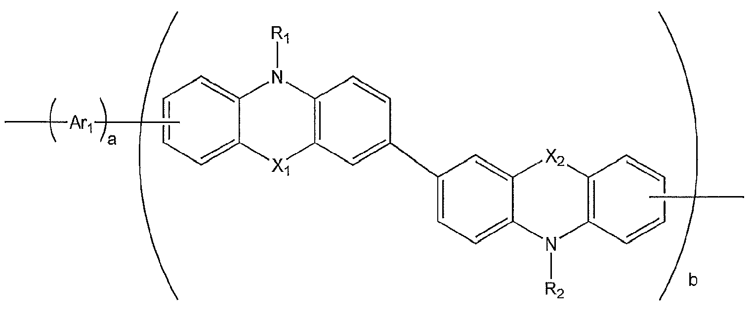
- a polymer represented by Formula 1 below is provided according to a first aspect of the present invention:
- Ar 1 are each independently represented by -(Q 1 ) n -.
- Q 1 is selected from the group consisting of a substituted or unsubstituted C 5 -C 30 arylene group, a substituted or unsubstituted C 4 -C 30 heteroarylene group, a substituted or unsubstituted C 2 -C 30 alkenylene group, and a group represented by -N(Z 1 )- and n is an integer from 1 to 10, and n groups of Q 1 in -(Q 1 ) n - are identical to or different from each other.
- X 1 and X 2 are each independently selected from the group consisting of -O-, -S-, -N(Z 2 )-, and -C(Z 3 )(Z 4 )-.
- Q 1 may be selected from the group consisting of a substituted or unsubstituted C 5 -C 14 arylene group, a substituted or unsubstituted C 4 -C 14 heteroarylene group, a substituted or unsubstituted C 2 -C 10 alkenylene group, and a group represented by -N(Z 1 )-, but is not limited thereto.
- Z 1 may be selected from the group consisting of hydrogen, a C 1 -C 10 alkyl group, a C 1 -C 10 alkoxy group, a C 5 -C 14 aryl group, and a C 4 -C 14 heteroaryl group.
- Z 1 may be selected from the group consisting of hydrogen, a C 1 -C 10 alkyl group, a C 1 -C 10 alkoxy group, a phenyl group, and a naphthyl group, but is not limited thereto.
- Q 1 may be selected from the group consisting of a C 2 -C 10 alkenylene group and functional groups represented by Formulae 2a through 2x below, but is not limited thereto:
- T 1 through T 4 may each independently be selected from the group consisting of hydrogen, a halogen atom, a cyano group, a hydroxyl group, a C 1 -C 10 alkyl group, a C 1 -C 10 alkoxy group, a C 2 -C 10 alkenyl group, a C 5 -C 14 aryl group, a C 4 -C 14 heteroaryl group, and a group represented by -N(Z 5 )(Z 6 ), and p, q, r, and s are each independently an integer from 0 through 4.
- Z 5 and Z 6 may be each independently selected from the group consisting of hydrogen, a halogen atom, a cyano group, a hydroxyl group, a C 1 -C 10 alkyl group, a C 1 -C 10 alkoxy group, a C 2 -C 10 alkenyl group, a C 5 -C 14 aryl group, and a C 4 -C 14 heteroaryl group.
- T 1 through T 4 may be each independently selected from the group consisting of hydrogen, a C 1 -C 10 alkyl group, a C 1 -C 10 alkoxy group, a phenyl group, a naphthyl group, and a group represented by -N(Z 5 )(Z 6 ), and Z 5 and Z 6 may be each independently selected from the group consisting of hydrogen, a C 1 -C 10 alkyl group, a C 1 -C 10 alkoxy group, a phenyl group, and a naphthyl group, but are not limited thereto.
- p, q, r, and s may be each independently 0, 1, or 2, but are not limited thereto.
- p groups of T 1 in -(T 1 ) p may be identical to or different from each other
- q groups of T 2 in -(T 2 ) q may be identical to or different from each other
- r groups of T 3 in -(T 3 ) r may be identical to or different from each other
- s groups of T 4 in -(T 4 ) s may be identical to or different from each other.
- the two groups of T 1 may be both methyl groups, or one of the two may be a methyl group and the other may be a phenyl group.
- n may be an integer from 1 to 10.
- n may be 1, 2, 3, 4, 5, 6, 7, 8, 9 or 10 but is not limited thereto.
- n groups of Q 1 in -(Q 1 ) n - may be identical to or different from each other.
- the two groups of Q 1 may be both phenylene groups, or one of the two may be a phenylene group and the other may be an ethenylene group.
- Ar 1 may be each independently of the groups represented by Formulae 2a through 2x and Formulae 3a through 31 below, but are not limited thereto:
- T 1 through T 4 , p, q, r, and s are as defined above.
- Ar 1 of Formula 1 may be represented by a formula selected from the group consisting of Formulae 2a through 2x.
- Ar 1 of Formula 1 is represented by Formula 2d, wherein T 1 and T 2 of Formula 2d are hydrogen, T 3 and T 4 are each independently selected from the group consisting of hydrogen, a C 1 -C 10 alkyl group, and a C 1 -C 10 alkoxy group.
- Ar 1 of Formula 1 is represented by Formula 2e, and T 1 and T 2 of Formula 2e are hydrogen, and T 3 and T 4 are each independently selected from the group consisting of hydrogen, a C 1 -C 10 alkyl group, and a C 1 -C 10 alkoxy group.
- X 1 and X 2 of Formula 1 may be each independently selected from the group consisting of -O-, - S-, -N(Z 2 )-, and -C(Z 3 )(Z 4 )-.
- Z 2 through Z 4 may be each independently selected from the group consisting of hydrogen, a substituted or unsubstituted C 1 -C 30 alkyl group, a substituted or unsubstituted C 2 -C 30 alkenyl group, a substituted or unsubstituted C 2 -C 30 alkynyl group, a substituted or unsubstituted C 1 -C 30 alkoxy group, a substituted or unsubstituted C 3 -C 12 cycloalkyl group, a substituted or unsubstituted C 3 -C 12 cycloheteroalkyl group, a substituted or unsubstituted C 5 -C 30 aryl group, and a substituted or unsubstituted C 4 -C 30 heteroaryl group.
- Z 2 through Z 4 may each be selected from the group consisting of hydrogen, a C 1 -C 10 alkyl group, a C 1 -C 10 alkoxy group, a C 5 -C 14 aryl group, and a C 4 -C 14 heteroaryl group.
- Z 2 through Z 4 may each be selected from the group consisting of hydrogen, a C 1 -C 10 alkyl group, a C 1 -C 10 alkoxy group, a phenyl group, and a naphthyl group, but are not limited thereto.
- X 1 and X 2 of Formula 1 may both be -O-.
- R 1 and R 2 may be each independently selected from the group consisting of hydrogen, a substituted or unsubstituted C 1 -C 30 alkyl group, a substituted or unsubstituted C 2 -C 30 alkenyl group, a substituted or unsubstituted C 2 -C 30 alkynyl group, a substituted or unsubstituted C 1 -C 30 alkoxy group, a substituted or unsubstituted C 3 -C 12 cycloalkyl group, a substituted or unsubstituted C 3 -C 12 cycloheteroalkyl group, a substituted or unsubstituted C 5 -C 30 aryl group, and a substituted or unsubstituted C 4 -C 30 heteroaryl group.
- R 1 and R 2 may each be selected from the group consisting of hydrogen, a substituted or unsubstituted C 1 -C 10 alkyl group, a substituted or unsubstituted C 1 -C 10 alkoxy group, a substituted or unsubstituted C 5 -C 14 aryl group, and a substituted or unsubstituted C 4 -C 14 heteroaryl group, but are not limited thereto.
- R 1 and R 2 of Formula 1 may be each independently represented by Formula 4a below:
- T 10 may be selected from the group consisting of hydrogen, a halogen atom, a hydroxyl group, a cyano group, a C 1 -C 10 alkyl group, a C 1 -C 10 alkoxy group, a C 5 -C 14 aryl group, and a C 4 -C 14 heteroaryl group, and m groups of T 10 of -(T 10 ) m may be identical to or different from each other, and m is an integer from 0 through 4.
- T 10 in Formula 4a may be selected from the group consisting of hydrogen, a C 1 -C 10 alkyl group, and a C 1 -C 10 alkoxy group, and m may be 1, but are not limited thereto.
- a and b may be each independently an actual number in a range of 0.3 to 0.7.
- a and b may each be 0.5, but are not limited thereto.
- a may be 0.6 to 0.7, and b may be 0.3 to 0.4, but are not limited thereto.
- R 1 and R 2 may be represented by Formula 4a.
- the polymer may be represented by Formula 5 below:
- Ar 1 , X 1 , X 2 , T 10 , m, a, and b are as defined above.
- the polymer may be represented by Formula 5, wherein in Formula 5, X 1 and X 2 are -O-.
- a and b may be each independently an actual number from 0.3 to 0.7.
- a and b may be 0.5, but are not limited thereto.
- a may be from 0.6 to 0.7
- b may be from 0.3 to 0.4, but are not limited thereto.
- the polymer represented by Formula 1 may have a weight average molecular weight (Mw) of from about 10,000 to about 200,000. When the polymer represented by Formula 1 is in the above range of the Mw, a satisfactory thermal stability may be provided.
- Mw weight average molecular weight
- the polymer of Formula 1 may have a polydispersion index (PDI) of from about 1.5 to about 5.
- PDI polydispersion index
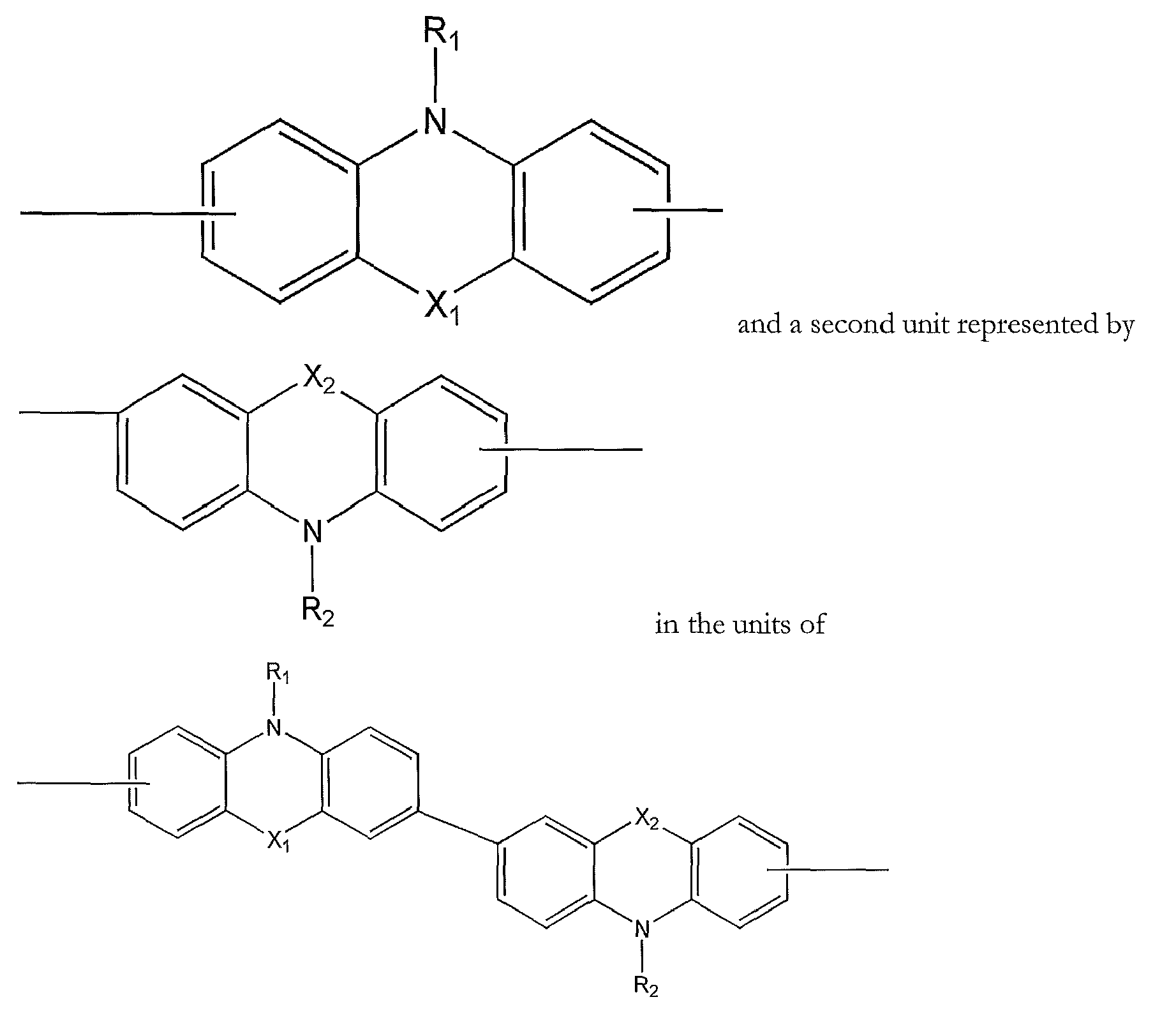
- a first unit represented by of the polymer represented by of Formula 1 above are positioned in different planes, and thus conjugation between the first and second units is broken. Accordingly, the polymer represented by Formula 1 has an increased band gap, and thus when the polymer is used as a material for a hole transporting layer (HTL), the effect of blocking movement of electrons and excitons in the EML is expected, and thus an OLED having a high efficiency and a long lifetime may be manufactured by using the polymer of Formula 1.
- HTL hole transporting layer
- examples of the unsubstituted C 1 -C 30 alkyl group include methyl, ethyl, propyl, isobutyl, sec-butyl, pentyl, iso-amyl, and hexyl.
- the unsubstituted C 1 -C 30 alkyl group may be linear or a branch-type.
- At least one hydrogen atom is substituted with one selected from the group consisting of a halogen atom, a hydroxyl group, a nitro group, a cyano group, an amino group, an amidino group, hydrazine, hydrazone, a carboxyl group or salts thereof, a sulfonic acid group or salts thereof, a phosphoric acid or salts thereof, a C 1 -C 30 alkyl group, a C 1 -C 30 alkenyl group, a C 1 -C 30 alkynyl group, a C 6 -C 30 aryl group, and a C 2 -C 20 heteroaryl group.
- the unsubstituted C 1 -C 30 alkoxy group (or C 1 -C 30 alkoxy group) is represented by -OA (A is the above-described unsubstituted C 1 -C 30 alkyl group), and examples of the unsubstituted C 1 -C 30 alkoxy group include methoxy, ethoxy, and isopropyloxy, and at least one hydrogen atom of the alkoxy group may be substituted with a substituent as in the case of the above-described substituted C 1 -C 30 alkyl group.
- -OA is the above-described unsubstituted C 1 -C 30 alkyl group
- examples of the unsubstituted C 1 -C 30 alkoxy group include methoxy, ethoxy, and isopropyloxy, and at least one hydrogen atom of the alkoxy group may be substituted with a substituent as in the case of the above-described substituted C 1 -C 30 alkyl group
- the unsubstituted C 2 -C 30 alkenyl group refers to a hydrocarbon chain having at least one carbon-carbon double bond in the center or at one end of the alkyl group structure.
- Examples of the alkenyl group include an ethenyl group, a propenyl group, and a butenyl group.
- At least one hydrogen atom in the substituted C 2 -C 30 alkenyl group is substituted with a substituent as in the case of the above-described substituted C 1 -C 30 alkyl group.
- the substituted or unsubstituted C 2 -C 30 alkenylene group refers to a divalent linking group having the same structure as the substituted or unsubstituted C 2 -C 30 alkenylene group described above.
- the unsubstituted C 2 -C 30 alkynyl group refers to a hydrocarbon chain having a carbon triple bond in the center or at one end of the C 2 -C 30 alkyl group structure.
- Examples of the unsubstituted C 2 -C 30 alkynyl group include acetylene (ethyne), propyne, isopropylacetylene, t-butylacetylene, and the like.
- At least one hydrogen atom of the substituted C 2 -C 30 alkynyl group is substituted with a substituent as in the case of the above-described C 1 -C 30 alkyl group.
- the unsubstituted C 5 -C 30 aryl group is a monovalent group having a carbocyclic aromatic system that includes at least one aromatic ring and has 5 to 30 carbon atoms.
- the unsubstituted C 5 -C 30 arylene group is a divalent group having a carbocyclic aromatic system that includes at least one aromatic ring and has 5 to 30 carbon atoms.
- the aryl group and the arylene group respectively include at least two rings, the at least two rings may be fused to each other.
- At least one hydrogen atom in the substituted C 5 -C 30 aryl group and the substituted C 5 -C 30 arylene group is substituted with the substituents described with reference to the substituted C 1 -C 30 alkyl group.
- Examples of the substituted or unsubstituted C 5 -C 30 aryl group include a phenyl group, a C 1 -C 10 alkylphenyl group (e.g., an ethylphenyl group), a C 1 -C 10 alkylbiphenyl group (e.g., an ethylbiphenyl group), a halophenyl group (e.g., an o-, m- or p-fluorophenyl group and a dichlorophenyl group), a dicyanophenyl group, a trifluoromethoxyphenyl group, an o-, m- or p-tolyl group, an o-, m- or p-cumenyl group, a mesityl group, a phenoxyphenyl group, a ( ⁇ , ⁇ -dimethylbenzene)phenyl group, a (N,N'-dimethyl)aminoph
- the unsubstituted C 4 -C 30 heteroaryl group is a monovalent group having a system including at least one aromatic ring, wherein the system has at least one of the heteroatoms selected from the group consisting of N, O, P, and S and the other ring atoms of the system are all carbon atoms.
- the unsubstituted C 2 -C 30 heteroarylene group is a bivalent group having a system including at least one aromatic ring, wherein the system has at least one of the heteroatoms selected from the group consisting of N, O, P, and S and the other ring atoms of the system are all carbon atoms.
- heteroaryl group and the heteroarylene group may be fused to each other.
- At least one hydrogen atom in the heteroaryl group and the heteroarylene group may be substituted with the substituents described with reference to the substituted C 1 -C 30 alkyl group.
- Examples of the unsubstituted C 4 -C 30 heteroaryl group include a pyrazolyl group, an imidazolyl group, an oxazolyl group, a thiazolyl group, a triazolyl group, a tetrazolyl group, an oxadiazolyl group, a pyridinyl group, a pyridazinyl group, a pyrimidinyl group, a triazinyl group, a carbazolyl group, an indolyl group, a quinolinyl group, an isoquinolinyl group, a benzoimidazolyl group, an imidazopyridinyl group, and an imidazopyrimidinyl group.
- Examples of the substituted or unsubstituted C 4 -C 30 heteroarylene group may be easily recognized with reference to the examples of the substituted or unsubstituted C 4 -C 30 aryl group.
- the polymer of Formula 1 may be synthesized by using a known organic synthesis method such as Suzuki coupling, Yamamoto coupling, etc.
- the synthesizing method of the polymer may be easily recognized by one having ordinary skill in the art with reference to examples to be described below.
- a polymerization reaction using Suzuki coupling may be performed using dihalide and a bisboronic acid or a bisborolane derivative in the presence of a palladium (0) catalyst under a basic condition.
- a polymerization reaction using Yamamoto coupling may be performed using only dihalide as a monomer in the presence of a nickel (0) catalyst, a base, and an additional ligand.
- the purity of the polymer is preferably high because low-molecular weight organic materials, ions, or other inorganic impurities may aggravate the light emitting characteristics (particularly, the lifetime characteristics) of an OLED manufactured using the polymer. Accordingly, by refining a crude polymer by using a repetitive precipitation method, a filter, a Soxhlet extractor, or the like, the purity of a final polymer may be improved.
- Reaction Scheme 1A is a reaction for synthesizing the polymer represented by Formula 1:
- each of Ha 1 and Ha 2 may be a halogen atom, for example, -F, -Cl, -Br or -I, or -B(OH) 2 , but is not limited thereto.
- Each of Ha3 and Ha4 may be a halogen atom, for example, -F, -Cl, - Br or -I, but is not limited thereto.
- Reaction Scheme 1A illustrates an example of a method of synthesizing the polymer represented by Formula 1.
- One of ordinary skill in the art may synthesize the polymer of Formula 1 by using an organic synthesis method well known in the art with reference to Reaction Scheme 1A and Formula 1.
- a first layer including the polymer represented by Formula 1 may be disposed between a first electrode and a second electrode of an OLED that includes a substrate, the first electrode, and the second electrode. Accordingly, an OLED including the substrate, the first electrode, the second electrode, and the polymer represented by Formula 1 and disposed between the first electrode and the second electrode is manufactured.
- the first layer may be a HTL or an electron transporting layer (ETL), but is not limited thereto.
- the first layer may be a HTL.
- the OLED may include at least one layer selected from the group consisting of a conductive buffer layer, a hole injection layer (HIL), a HTL, an emissive layer (EML), a hole blocking layer (HBL), an ETL, and an electron injection layer (EIL) between the first electrode and the second electrode.
- HIL hole injection layer
- EML emissive layer
- HBL hole blocking layer
- EIL electron injection layer
- the OLED may have a structure in which a substrate, a first electrode, a conductive buffer layer, a first layer which functions as a HTL, an EML, an ETL, an EIL, and a second electrode are sequentially stacked.
- the polymer may have an average weight molecular weight (Mw) of from about 10,000 through about 200,000.
- the substrate which may be any substrate that is used in conventional organic light-emitting devices, may be a glass substrate or a transparent plastic substrate with excellent mechanical strength, thermal stability, transparency, surface smoothness, ease of handling, and waterproofness.
- the first electrode may be formed by depositing or sputtering a material that is used to form the first electrode on the substrate.
- the material used to form the first electrode may be a high work-function material so as to facilitate hole injection.
- the first electrode may be a reflective electrode or a transmission electrode.
- Transparent and conductive materials such as ITO, IZO, SnO2, and ZnO may be used to form the first electrode.
- the first electrode may be formed using magnesium (Mg), aluminum (Al), aluminum-lithium (Al-Li), calcium (Ca), magnesium-indium (Mg-In), magnesium-silver (Mg-Ag), or the like.
- the conductive buffer layer may be disposed on the first electrode.
- the conductive buffer layer may be formed by spin coating, casting, Langmuir Blodgett (LB) deposition, or the like.
- coating conditions may vary according to a compound that is used to form the conductive buffer layer and the structure and thermal properties of the conductive buffer layer to be formed.
- the coating conditions may include a coating speed of about 2000 rpm to about 5000 rpm, and a thermal treatment temperature of about 80°C to about 200°C, wherein the thermal treatment is for removing a solvent after coating.
- Examples of a material for the conductive buffer layer include polyaniline/dodecylbenzenesulfonic acid (Pani/DBSA), poly(3,4-ethylenedioxythiophene)/poly(4-styrenesulfonate) (PEDOT/PSS), polyaniline/camphor sulfonic acid (Pani/CSA), and (polyaniline)/poly (4-styrene- sulfonate) (PANI/PSS), but are not limited thereto.
- Pani/DBSA polyaniline/dodecylbenzenesulfonic acid
- PEDOT/PSS poly(3,4-ethylenedioxythiophene)/poly(4-styrenesulfonate)
- Pani/CSA polyaniline/camphor sulfonic acid
- PANI/PSS polyaniline/poly (4-styrene- sulfonate
- the thickness of the conductive buffer layer may be from about 100 ⁇ to about 10000 ⁇ , for example, the thickness of the conductive buffer layer may be from about 100 ⁇ to about 1000 ⁇ . When the thickness of the conductive buffer layer is within this range, the HIL may have an excellent hole injecting ability without a substantial increase in a driving voltage.
- an HIL may further be included between the conductive buffer layer and the substrate or on the conductive buffer layer.
- the HIL may be formed by vacuum deposition, spin coating, casting, LB deposition, or the like.
- vacuum deposition conditions may vary according to a compound that is used to form the HIL and the desired structure and thermal properties of the HIL to be formed. In general, however, the vacuum deposition may be performed at a deposition temperature of about from 100°C to about 500°C, under a pressure of from about 10 -8 torr to about 10 -3 torr, and at a deposition speed of from about 0.01 ⁇ /sec to about 100 ⁇ /sec.
- conditions for the spin coating may vary according to a compound that is used to form the HIL, and the desired structure and thermal properties of the HIL to be formed; however, the conditions may be selected from the coating conditions for the conductive buffer layer.
- the HIL may be formed of any material that is commonly used to form an HIL.
- Examples of the material that can be used to form the HIL include N,N'-diphenyl-N,N'-bis-[4-(phenyl-m-tolyl-amino)-phenyl]-biphenyl-4,4'-diamine (DNTPD), a phthalocyanine compound such as copperphthalocyanine, 4,4',4"-tris (3-methylphenylphenylamino) triphenylamine (m-MTDATA), TDATA, 2T-NATA, but are not limited thereto.
- DNTPD N,N'-diphenyl-N,N'-bis-[4-(phenyl-m-tolyl-amino)-phenyl]-biphenyl-4,4'-diamine
- m-MTDATA 4,4',4"-tris (3-methylphenylphenylamino) triphenylamine
- the thickness of the HIL may be from about 100 ⁇ to about 10000 ⁇ , for example, the thickness of the HIL may be from about 100 ⁇ to about 1000 ⁇ . When the thickness of the HIL is within this range, the HIL may have an excellent hole injecting ability without a substantial increase in a driving voltage.
- a first layer including the polymer represented by Formula 1 may be formed as an HTL on the conductive buffer layer (or on the HIL, if HIL is formed) by vacuum deposition, spin coating, casting, LB deposition, or the like.
- Conditions for forming the first layer may be selected among, for example, the coating conditions for the conductive buffer layer.
- the thickness of the HTL including the polymer represented by Formula 1 may be from about 50 ⁇ to about 1000 ⁇ , and for example, the thickness of the HTL including the polymer represented by Formula 1 may be from about 100 ⁇ to about 800 ⁇ . When the thickness of the HTL is within the range described above, the HTL may have excellent hole transporting ability without a substantial increase in driving voltage.
- an EML may be formed on the HTL including the polymer represented by Formula 1 by vacuum deposition, spin coating, casting, LB deposition, or the like.
- the conditions for deposition and coating may be similar to those for the formation of the conductive buffer layer or the HIL, although the conditions for deposition and coating may vary according to the material that is used to form the EML.
- the EML may be formed of a light emitting material or a combination of a host and a dopant.
- the host include Alq3, 4,4'-N,N'- dicarbazole-biphenyl (CBP), poly(n-vinylcarbazole) (PVK), 9,10-di(naphthalene-2-yl)anthracene (ADN), TCTA, 1,3,5-tris(N-phenylbenzimidazole-2-yl)benzene (TPBI), 3-tert-butyl-9,10-di-2-naphthylanthracene (TBADN), E3, and distyrylarylene (DSA), but are not limited thereto.
- CBP 4,4'-N,N'- dicarbazole-biphenyl
- PVK poly(n-vinylcarbazole)
- ADN 9,10-di(naphthalene-2-yl)anthracene
- red dopants examples include PtOEP, Ir(piq) 3 , and Btp 2 Ir(acac), but are not limited thereto.
- blue dopants include F 2 Irpic, (F 2 ppy) 2 Ir(tmd), Ir(dfppz)3, ter-fluorene, 4,4'-bis(4-diphenylaminostyryl)biphenyl (DPAVBi), and 2,5,8,11-tetra-t-butyl pherylene (TBPe), but are not limited thereto.
- the content of the dopant may be from about 0.01 to about 15 parts by weight based on 100 parts by weight of the host, but is not limited thereto.
- the thickness of the EML may be from about 100 ⁇ to about 1000 ⁇ , and for example, the thickness of the EML may be from about 200 ⁇ to about 600 ⁇ . When the thickness of the EML is within this range, the EML may have excellent light emitting ability without a substantial increase in a driving voltage.
- An HBL may be formed between the HTL and the EML using vacuum deposition, spin coating, casting, LB deposition, or the like, to prevent diffusion of triplet excitons or holes into an ETL when a phosphorescent dopant is used to form the EML.
- the conditions for deposition and coating may be similar to those for the formation of the conductive buffer layer or the HIL, although the conditions for deposition and coating may vary according to the material that is used to form the HBL. Any material that is commonly used to form a HBL may be used. Examples of materials for forming the HBL include an oxadiazole derivative, a triazole derivative, and a phenanthroline derivative, but are not limited thereto.
- the thickness of the HBL may be from about 50 ⁇ to about 1000 ⁇ , and for example, the thickness of the HBL may be from about 100 ⁇ to about 300 ⁇ . When the thickness of the HBL is within this range, the HBL may have an excellent hole blocking ability without a substantial increase in a driving voltage.
- an ETL may be formed on the EML by vacuum deposition, spin coating, casting, or the like.
- the deposition and coating conditions may be similar to those for formation of the conductive buffer layer or the HIL, although the deposition and coating conditions may vary according to a compound that is used to form the ETL.
- a material that is used to form the ETL may be a material that can stably transport electrons injected from the electron injecting electrode (cathode) and any known material may be used.
- Examples of materials for forming the ETL include a quinoline derivative, tris(8-quinolinorate)aluminum (Alq 3 ), TAZ, and Balq, beryllium bis(benzoquinolin-10-olate: Bebq 2 ), but are not limited thereto.
- the thickness of the ETL may be from about 100 ⁇ to about 1000 ⁇ , and for example, the thickness of the ETL may be from about 150 ⁇ to about 500 ⁇ . When the thickness of the ETL is within this range, the ETL may have satisfactory electron transporting ability without a substantial increase in a driving voltage.
- An EIL may be formed on the ETL.
- the EIL may be formed of any material allowing electrons to be easily injected from the cathode.
- Examples of materials for forming the EIL include LiF, NaCl, CsF, Li 2 O, and BaO, which are known in the art.
- Deposition and coating conditions for forming the EIL are similar to those for formation of the HIL, although the deposition and coating conditions may vary according to a material that is used to form the EIL.
- the thickness of the EIL may be from about 1 ⁇ to about 100 ⁇ , for example, the thickness of the EIL may be from about 3 ⁇ to about 90 ⁇ . When the thickness of the EIL is within this range, the EIL may have satisfactory electron injection ability without a substantial increase in a driving voltage.
- a second electrode is formed on the EIL.
- the second electrode may be a cathode that is an electron injection electrode.
- a metal for forming the second electrode may be a metal, an alloy, an electro-conductive compound, or mixtures thereof that respectively have a low work function.
- the second electrode may be formed of lithium (Li), magnesium (Mg), aluminum (Al), aluminum (Al)-lithium (Li), calcium (Ca), magnesium (Mg)-indium (In), magnesium (Mg)-silver (Ag), or the like, and may be formed as a thin film type transmission electrode.
- the transmission electrode may be formed of ITO or IZO to manufacture a top-emission type light-emitting device.
- the method of manufacturing an OLED including the first layer including the polymer represented by Formula 1 which functions as a HTL has been described above; however, the first layer including the polymer represented by Formula 1 may also function not only as an HTL but also an EML, an ETL, or the like, according to the substituent included in the first layer.
- the HTL may be formed by using known hole transporting materials.
- the hole transporting material include: a carbazole derivative such as N-phenylcarbazole or polyvinylcarbazole; an amine derivative having an aromatic condensation ring, such as N,N'-bis(3-methylphenyl)-N,N'-diphenyl-[1,1-biphenyl]-4,4'-diamine (TPD) illustrated below or N,N'-di(naphthalene-1-yl)-N,N'-diphenyl benzidine ( ⁇ -NPD) illustrated below; and a triphenylamine-based material, such as 4,4',4"-tris(N-carbazolyl)triphenylamine (TCTA).
- TCTA may not only transport holes but also inhibit excitons from being diffused into the EML.
- a Schlenk flask was vacuumized and refluxed under a nitrogen atmosphere several times to completely eliminate water, and then 880 mg (3.2 mmol) of bis 1,5-cyclooctadiene nickel and 500 mg (3.2 mmol) of bipyridal were input in a glove box, and the flask was vacuumized and refluxed under a nitrogen atmosphere again several times. Next, under a nitrogen atmosphere, 10 ml of anhydrate dimethylfurane (DMF), 346 mg (3.2 mmol) of 1,5-cyclooctadiene (COD), and 10 ml of anhydrate toluene were added thereto.
- DMF dimethylfurane
- COD 1,5-cyclooctadiene
- Polymer 1 was synthesized through Reaction Scheme 3 below: 9.31 g (10.00 mmol) of Compound (e) and 4.83 g (10.1 mmol) of Compound (f), and 4.15g (30.00 mmol) of K 2 CO 3 were melted in a mixture solution of 50 ml of toluene, 50 ml of water, and 0.5 ml of ethanol, and 230 mg (0.02 mmol) of Pd(PPh 3 ) 4 was added thereto in a nitrogen atmosphere. The reactant mixture was charged in a nitrogen atmosphere and stirred at a temperature of 87°C and was weakly refluxed. After three days, 16 mg of bromobenzene was added thereto. Then, the mixture was refluxed for 1 day.
- Polymer 2 was synthesized according to Reaction Scheme 4 below: 9.31 g (10.00 mmol) of Compound (e) and 4.08 g (10.1 mmol) of Compound (g), and 4.15g (30.00 mmol) of K 2 CO 3 were melted in a mixture solution of 50 ml of toluene, 50 ml of water, and 0.5 ml of ethanol, and 230 mg (0.02 mmol) of Pd(PPh3)4 was added thereto in a nitrogen atmosphere. The reactant mixture was weakly refluxed while stirring at a temperature of 87°C under a nitrogen atmosphere. After three days, 16 mg of bromobenzene was added thereto. Then, the solution was refluxed for 1 day.
- Polymer 3 was synthesized according to Reaction Scheme 5 below: 4.13 g (15.0 mmol) of Ni(COD) 2 and 2.31 g (15.0 mmol) of 2-2'-bipyridyl were put into a flask in a glove box and 75 ml of dimethylformamide and 240 ml of toluene were added thereto, and heated at 80°C under a nitrogen atmosphere.
- a 15 ⁇ /cm 2 (1200 ⁇ ) ITO glass substrate by Corning was cut to a size of 50 mm ⁇ 50 mm ⁇ 0.7 mm, ultrasonically washed with isopropyl alcohol and pure water for 5 minutes each, and then washed with UV ozone for 30 minutes.
- PEDOT:PSS poly(3,4-ethylenedioxythiophene) poly(styrenesulfonate, AI4083, available by H. C. Stark
- HTL hole transporting layer
- Alq 3 was vacuum-deposited on the EML to form an ETL having a thickness of 200 ⁇ .
- LiF having a thickness of 80 ⁇ and Al having a thickness of 3000 ⁇ were sequentially vacuum-deposited on the ETL to form an EIL and a cathode to manufacture an OLED.
- the thickness of layers and the growth speed thereof during the deposition are adjusted by using a crystal sensor.
- An OLED was manufactured in the same manner as Example 1 except that Polymer 2 of Synthesis Example 3 was used instead of Polymer 1 to form an HTL of Example 1.
- An OLED was manufactured in the same manner as Example 1 except that Polymer 3 of Synthesis Example 4 was used instead of Polymer 1 to form an HTL of Example 1.
- An OLED was manufactured in the same manner as Example 1 except that an EML was formed on the conductive buffer layer without forming the HTL in Example 1.
- An OLED was manufactured in the same manner as Example 1 except that Polymer A below was used instead of Polymer 1 to form an HTL in Example 1.
- Polymer A was analyzed by GPC. As a result, a Mw of Polymer A was 58,000 and a dispersion degree of Polymer A was 2.7.
- Luminance (cd/m2), efficiency (cd/A), and lifetime of the OLEDs of Example 1, Example 2, Example 3, Comparative Example 1, and Comparative Example 2 were measured by using a PR650 (Spectroscan) Source Measurement Unit and results thereof are shown in Table 1. The lifetime was evaluated by measuring the time when the initial luminance of 100cd/m 2 is reduced by half. Table 1 HTL Efficiency (cd/A) Half lifetime (time)@100 cd/m 2 Example 1 Polymer 1 4.39 2000 Example 2 Polymer 2 4.76 2400 Example 3 Polymer 3 3.9 2200 Comparative Example 1 HTL is not formed. 1.32 13 Comparative Example 2 Polymer A 3.16 1800
- the OLEDs of Examples 1 through 3 have better efficiency and lifetime characteristics than the OLED of Comparative Examples 1 and 2.
Landscapes
- Chemical & Material Sciences (AREA)
- Health & Medical Sciences (AREA)
- Chemical Kinetics & Catalysis (AREA)
- Medicinal Chemistry (AREA)
- Polymers & Plastics (AREA)
- Organic Chemistry (AREA)
- Engineering & Computer Science (AREA)
- Materials Engineering (AREA)
- Physics & Mathematics (AREA)
- Optics & Photonics (AREA)
- Electroluminescent Light Sources (AREA)
- Polyoxymethylene Polymers And Polymers With Carbon-To-Carbon Bonds (AREA)
Abstract
Description
- The present invention relates to a polymer and an organic light-emitting device including the polymer.
- Organic light-emitting self emissive devices include a pair of electrodes and an organic layer interposed between the electrodes, and when a current is supplied to the electrodes, electrons and holes injected through the electrodes are combined in the organic layer, thereby emitting light. Organic light-emitting devices are lightweight, and can be easily manufactured using a relatively small number of components. In addition, organic light-emitting devices provide high-quality images and have wide viewing angles. Furthermore, organic light-emitting devices provide high color purity, accurately realize mobile images, have low power consumption, and can be operated at low voltage. Due to these characteristics, organic light-emitting devices are suitable for mobile electronic devices.
- A typical OLED has a structure including a substrate, an anode disposed on the substrate, and a hole transporting layer (HTL), an emissive layer (EML), an electron transporting layer (ETL), and a cathode which are sequentially stacked on the anode.
- When a current is applied to the anode and the cathode, holes injected from the anode move to the EML via the HTL, and electrons injected from the cathode move to the EML via the ETL. The holes and electrons recombine in the EML to generate excitons. The excitons are radiatively decayed, thereby emitting light having a wavelength corresponding to a band gap of a corresponding material.
- A polymer for manufacturing an organic light-emitting device (OLED) having a high efficiency and a long lifetime is provided.
- An OLED including the polymer is also provided.
- In a first aspect of the present invention, there is provided a polymer represented by Formula 1 below:

X1 and X2 are each independently selected from the group consisting of -O-, -S-, -N(Z2)-, and - C(Z3)(Z4)-, and
R1, R2, Z1, Z2, Z3, and Z4 are each independently selected from the group consisting of hydrogen, a substituted or unsubstituted C1-C30 alkyl group, a substituted or unsubstituted C2-C30 alkenyl group, a substituted or unsubstituted C2-C30 alkynyl group, a substituted or unsubstituted C1-C30 alkoxy group, a substituted or unsubstituted C3-C12 cycloalkyl group, a substituted or unsubstituted C3-C12 cycloheteroalkyl group, a substituted or unsubstituted C5-C30 aryl group, and a substituted or unsubstituted C4-C30 heteroaryl group, and a and b are independently an actual number in a range of from 0.01 to 0.99, wherein a+b=1. - In a second aspect of the present invention there is provided an organic light emitting device (OLED) comprising: a substrate; a first electrode; a second electrode; and a first layer comprising the polymer of the invention in its first aspect, disposed between the first and second electrodes.
- A more complete appreciation of the present invention, and many of the attendant advantages thereof, will be readily apparent as the same becomes better understood by reference to the following detailed description when considered in conjunction with the accompanying drawings, wherein:
-
Figure 1 is a cross-sectional view illustrating an organic light-emitting device (OLED) according to an embodiment of the present invention. - A polymer represented by Formula 1 below is provided according to a first aspect of the present invention:

- In Formula 1, Ar1 are each independently represented by -(Q1)n-.
- Q1 is selected from the group consisting of a substituted or unsubstituted C5-C30 arylene group, a substituted or unsubstituted C4-C30 heteroarylene group, a substituted or unsubstituted C2-C30 alkenylene group, and a group represented by -N(Z1)- and n is an integer from 1 to 10, and n groups of Q1 in -(Q1)n- are identical to or different from each other. X1 and X2 are each independently selected from the group consisting of -O-, -S-, -N(Z2)-, and -C(Z3)(Z4)-. R1, R2, Z1, Z2, Z3 and Z4 are each independently selected from the group consisting of hydrogen, a substituted or unsubstituted C1-C30 alkyl group, a substituted or unsubstituted C2-C30 alkenyl group, a substituted or unsubstituted C2-C30 alkynyl group, a substituted or unsubstituted C1-C30 alkoxy group, a substituted or unsubstituted C3-C12 cycloalkyl group, a substituted or unsubstituted C3-C12 cycloheteroalkyl group, a substituted or unsubstituted C5-C30 aryl group, and a substituted or unsubstituted C4-C30 heteroaryl group and, a and b are independently an actual number from 0.01 to 0.99, wherein a+b=1.
- For example, Q1 may be selected from the group consisting of a substituted or unsubstituted C5-C14 arylene group, a substituted or unsubstituted C4-C14 heteroarylene group, a substituted or unsubstituted C2-C10 alkenylene group, and a group represented by -N(Z1)-, but is not limited thereto. Z1 may be selected from the group consisting of hydrogen, a C1-C10 alkyl group, a C1-C10 alkoxy group, a C5-C14 aryl group, and a C4-C14 heteroaryl group. For example, Z1 may be selected from the group consisting of hydrogen, a C1-C10 alkyl group, a C1-C10 alkoxy group, a phenyl group, and a naphthyl group, but is not limited thereto.
- In some embodiments, Q1 may be selected from the group consisting of a C2-C10 alkenylene group and functional groups represented by Formulae 2a through 2x below, but is not limited thereto:


- In Formulae 2a through 2x, T1 through T4 may each independently be selected from the group consisting of hydrogen, a halogen atom, a cyano group, a hydroxyl group, a C1-C10 alkyl group, a C1-C10 alkoxy group, a C2-C10 alkenyl group, a C5-C14 aryl group, a C4-C14 heteroaryl group, and a group represented by -N(Z5)(Z6), and p, q, r, and s are each independently an integer from 0 through 4. Z5 and Z6 may be each independently selected from the group consisting of hydrogen, a halogen atom, a cyano group, a hydroxyl group, a C1-C10 alkyl group, a C1-C10 alkoxy group, a C2-C10 alkenyl group, a C5-C14 aryl group, and a C4-C14 heteroaryl group.
- For example, in Formulae 2a through 2x, T1 through T4 may be each independently selected from the group consisting of hydrogen, a C1-C10 alkyl group, a C1-C10 alkoxy group, a phenyl group, a naphthyl group, and a group represented by -N(Z5)(Z6), and Z5 and Z6 may be each independently selected from the group consisting of hydrogen, a C1-C10 alkyl group, a C1-C10 alkoxy group, a phenyl group, and a naphthyl group, but are not limited thereto.
- For example, p, q, r, and s may be each independently 0, 1, or 2, but are not limited thereto.
- In Formulae 2a through 2x, p groups of T1 in -(T1)p may be identical to or different from each other, q groups of T2 in -(T2)q may be identical to or different from each other, r groups of T3 in -(T3)r may be identical to or different from each other, and s groups of T4 in -(T4)s may be identical to or different from each other. For example, when p is 2, the two groups of T1 may be both methyl groups, or one of the two may be a methyl group and the other may be a phenyl group.
- n may be an integer from 1 to 10. For example, n may be 1, 2, 3, 4, 5, 6, 7, 8, 9 or 10 but is not limited thereto.
- n groups of Q1 in -(Q1)n- may be identical to or different from each other. For example, when n is 2, the two groups of Q1 may be both phenylene groups, or one of the two may be a phenylene group and the other may be an ethenylene group.
- In Formula 1, Ar1 may be each independently of the groups represented by Formulae 2a through 2x and Formulae 3a through 31 below, but are not limited thereto:


- In the above Formulae 2a through 2x and 3a through 31, T1 through T4, p, q, r, and s are as defined above.
- When n is 1, Ar1 of Formula 1 may be represented by a formula selected from the group consisting of Formulae 2a through 2x.
- In an embodiment of the invention, Ar1 of Formula 1 is represented by Formula 2d, wherein T1 and T2 of Formula 2d are hydrogen, T3 and T4 are each independently selected from the group consisting of hydrogen, a C1-C10 alkyl group, and a C1-C10 alkoxy group.
- In another embodiment, Ar1 of Formula 1 is represented by Formula 2e, and T1 and T2 of Formula 2e are hydrogen, and T3 and T4 are each independently selected from the group consisting of hydrogen, a C1-C10 alkyl group, and a C1-C10 alkoxy group.
- X1 and X2 of Formula 1 may be each independently selected from the group consisting of -O-, - S-, -N(Z2)-, and -C(Z3)(Z4)-.
- Z2 through Z4 may be each independently selected from the group consisting of hydrogen, a substituted or unsubstituted C1-C30 alkyl group, a substituted or unsubstituted C2-C30 alkenyl group, a substituted or unsubstituted C2-C30 alkynyl group, a substituted or unsubstituted C1-C30 alkoxy group, a substituted or unsubstituted C3-C12 cycloalkyl group, a substituted or unsubstituted C3-C12 cycloheteroalkyl group, a substituted or unsubstituted C5-C30 aryl group, and a substituted or unsubstituted C4-C30 heteroaryl group. For example, Z2 through Z4 may each be selected from the group consisting of hydrogen, a C1-C10 alkyl group, a C1-C10 alkoxy group, a C5-C14 aryl group, and a C4-C14 heteroaryl group. Z2 through Z4 may each be selected from the group consisting of hydrogen, a C1-C10 alkyl group, a C1-C10 alkoxy group, a phenyl group, and a naphthyl group, but are not limited thereto.
- In an embodiment, X1 and X2 of Formula 1 may both be -O-.
- In Formula 1, R1 and R2 may be each independently selected from the group consisting of hydrogen, a substituted or unsubstituted C1-C30 alkyl group, a substituted or unsubstituted C2-C30 alkenyl group, a substituted or unsubstituted C2-C30 alkynyl group, a substituted or unsubstituted C1-C30 alkoxy group, a substituted or unsubstituted C3-C12 cycloalkyl group, a substituted or unsubstituted C3-C12 cycloheteroalkyl group, a substituted or unsubstituted C5-C30 aryl group, and a substituted or unsubstituted C4-C30 heteroaryl group. For example, R1 and R2 may each be selected from the group consisting of hydrogen, a substituted or unsubstituted C1-C10 alkyl group, a substituted or unsubstituted C1-C10 alkoxy group, a substituted or unsubstituted C5-C14 aryl group, and a substituted or unsubstituted C4-C14 heteroaryl group, but are not limited thereto.
- R1 and R2 of Formula 1 may be each independently represented by Formula 4a below:

- In Formula 4a, T10 may be selected from the group consisting of hydrogen, a halogen atom, a hydroxyl group, a cyano group, a C1-C10 alkyl group, a C1-C10 alkoxy group, a C5-C14 aryl group, and a C4-C14 heteroaryl group, and m groups of T10 of -(T10)m may be identical to or different from each other, and m is an integer from 0 through 4.
- For example, in Formula 4a, T10 in Formula 4a may be selected from the group consisting of hydrogen, a C1-C10 alkyl group, and a C1-C10 alkoxy group, and m may be 1, but are not limited thereto.
- In Formula 1, a and b denote moles of respective units, and may be each independently an actual number in a range of 0.01 to 0.99, wherein a+b=1.
- For example, a and b may be each independently an actual number in a range of 0.3 to 0.7.
- For example, a and b may each be 0.5, but are not limited thereto.
- Also, for example, a may be 0.6 to 0.7, and b may be 0.3 to 0.4, but are not limited thereto.
- According to another embodiment, in Formula 1, R1 and R2 may be represented by Formula 4a. Thus, the polymer may be represented by Formula 5 below:
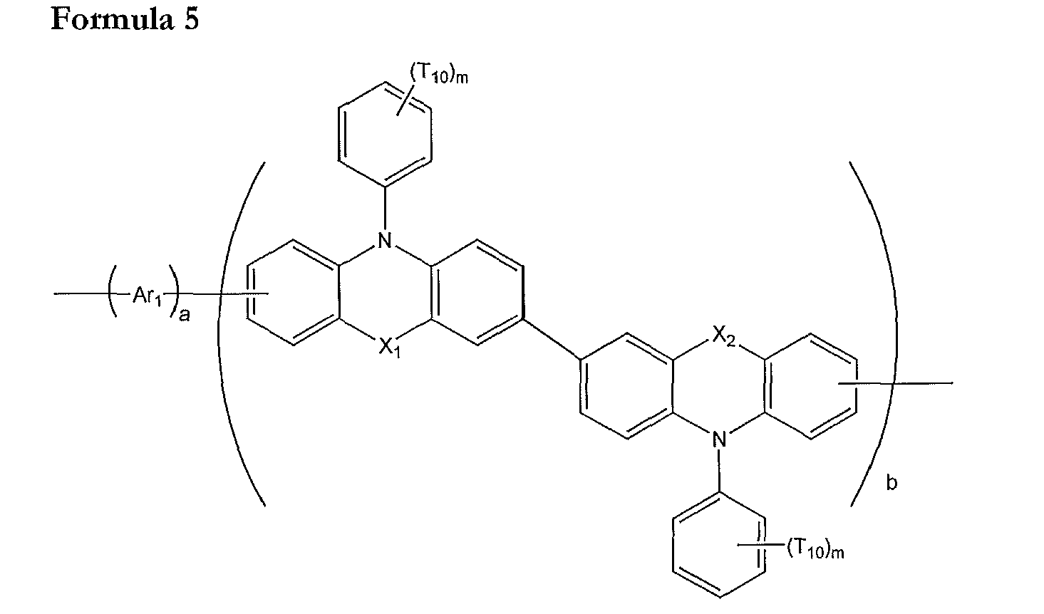
- In Formula 5, Ar1, X1, X2, T10, m, a, and b are as defined above.
- According to another embodiment, the polymer may be represented by Formula 5, wherein in Formula 5, X1 and X2 are -O-.
- According to another embodiment, the polymer is represented by Formula 6 or Formula 7 below:


- The polymer represented by Formula 1 may have a weight average molecular weight (Mw) of from about 10,000 to about 200,000. When the polymer represented by Formula 1 is in the above range of the Mw, a satisfactory thermal stability may be provided.
- The polymer of Formula 1 may have a polydispersion index (PDI) of from about 1.5 to about 5. When the polymer represented by Formula 1 has the above-described PDI, a satisfactory thermal stability may be provided.
- Although not limited to a specific theory, a first unit represented by
- In the current specification, examples of the unsubstituted C1-C30 alkyl group (or C1-C30 alkyl group) include methyl, ethyl, propyl, isobutyl, sec-butyl, pentyl, iso-amyl, and hexyl. The unsubstituted C1-C30 alkyl group may be linear or a branch-type. In the substituted C1-C30 alkyl group used herein, at least one hydrogen atom is substituted with one selected from the group consisting of a halogen atom, a hydroxyl group, a nitro group, a cyano group, an amino group, an amidino group, hydrazine, hydrazone, a carboxyl group or salts thereof, a sulfonic acid group or salts thereof, a phosphoric acid or salts thereof, a C1-C30 alkyl group, a C1-C30 alkenyl group, a C1-C30 alkynyl group, a C6-C30 aryl group, and a C2-C20 heteroaryl group.
- In the current specification, the unsubstituted C1-C30 alkoxy group (or C1-C30 alkoxy group) is represented by -OA (A is the above-described unsubstituted C1-C30 alkyl group), and examples of the unsubstituted C1-C30 alkoxy group include methoxy, ethoxy, and isopropyloxy, and at least one hydrogen atom of the alkoxy group may be substituted with a substituent as in the case of the above-described substituted C1-C30 alkyl group.
- The unsubstituted C2-C30 alkenyl group (or C2-C30 alkenyl group) refers to a hydrocarbon chain having at least one carbon-carbon double bond in the center or at one end of the alkyl group structure. Examples of the alkenyl group include an ethenyl group, a propenyl group, and a butenyl group. At least one hydrogen atom in the substituted C2-C30 alkenyl group is substituted with a substituent as in the case of the above-described substituted C1-C30 alkyl group. The substituted or unsubstituted C2-C30 alkenylene group refers to a divalent linking group having the same structure as the substituted or unsubstituted C2-C30 alkenylene group described above.
- The unsubstituted C2-C30 alkynyl group (or C2-C30 alkynyl group) refers to a hydrocarbon chain having a carbon triple bond in the center or at one end of the C2-C30 alkyl group structure. Examples of the unsubstituted C2-C30 alkynyl group include acetylene (ethyne), propyne, isopropylacetylene, t-butylacetylene, and the like. At least one hydrogen atom of the substituted C2-C30 alkynyl group is substituted with a substituent as in the case of the above-described C1-C30 alkyl group.
- The unsubstituted C5-C30 aryl group is a monovalent group having a carbocyclic aromatic system that includes at least one aromatic ring and has 5 to 30 carbon atoms. The unsubstituted C5-C30 arylene group is a divalent group having a carbocyclic aromatic system that includes at least one aromatic ring and has 5 to 30 carbon atoms. When the aryl group and the arylene group respectively include at least two rings, the at least two rings may be fused to each other. At least one hydrogen atom in the substituted C5-C30 aryl group and the substituted C5-C30 arylene group is substituted with the substituents described with reference to the substituted C1-C30 alkyl group.
- Examples of the substituted or unsubstituted C5-C30 aryl group include a phenyl group, a C1-C10 alkylphenyl group (e.g., an ethylphenyl group), a C1-C10 alkylbiphenyl group (e.g., an ethylbiphenyl group), a halophenyl group (e.g., an o-, m- or p-fluorophenyl group and a dichlorophenyl group), a dicyanophenyl group, a trifluoromethoxyphenyl group, an o-, m- or p-tolyl group, an o-, m- or p-cumenyl group, a mesityl group, a phenoxyphenyl group, a (α,α-dimethylbenzene)phenyl group, a (N,N'-dimethyl)aminophenyl group, a (N,N'-diphenyl)aminophenyl group, a pentalenyl group, an indenyl group, a naphthyl group, a halonaphthyl group (e.g., a fluoronaphthyl group), a C1-C10 alkylnaphthyl group (e.g., a methylnaphthyl group), a C1-C10 alkoxynaphthyl group (e.g., a methoxynaphthyl group), an anthracenyl group, an azulenyl group, a heptalenyl group, an acenaphthylenyl group, a phenalenyl group, a fluorenyl group, an anthraquinolyl group, a methylanthryl group, a phenanthryl group, a triphenylenyl group, a pyrenyl group, a chrysenyl group, an ethyl-chrysenyl group, a picenyl group, a perylenyl group, a chloroperylenyl group, a pentaphenyl group, a pentacenyl group, a tettaphenylenyl group, a hexaphenyl group, hexacenyl group, a rubicenyl group, a coronenyl group, a trinaphthylenyl group, a heptaphenyl group, a heptacenyl group, a pyranthrenyl group, and an ovalenyl group. Examples of the substituted or unsubstituted C5-C30 arylene group may be easily recognized with reference to the examples of the substituted or unsubstituted C5-C30 aryl group.
- The unsubstituted C4-C30 heteroaryl group is a monovalent group having a system including at least one aromatic ring, wherein the system has at least one of the heteroatoms selected from the group consisting of N, O, P, and S and the other ring atoms of the system are all carbon atoms. The unsubstituted C2-C30 heteroarylene group is a bivalent group having a system including at least one aromatic ring, wherein the system has at least one of the heteroatoms selected from the group consisting of N, O, P, and S and the other ring atoms of the system are all carbon atoms. In this regard, if the heteroaryl group and the heteroarylene group have at least two rings, they may be fused to each other. At least one hydrogen atom in the heteroaryl group and the heteroarylene group may be substituted with the substituents described with reference to the substituted C1-C30 alkyl group.
- Examples of the unsubstituted C4-C30 heteroaryl group include a pyrazolyl group, an imidazolyl group, an oxazolyl group, a thiazolyl group, a triazolyl group, a tetrazolyl group, an oxadiazolyl group, a pyridinyl group, a pyridazinyl group, a pyrimidinyl group, a triazinyl group, a carbazolyl group, an indolyl group, a quinolinyl group, an isoquinolinyl group, a benzoimidazolyl group, an imidazopyridinyl group, and an imidazopyrimidinyl group. Examples of the substituted or unsubstituted C4-C30 heteroarylene group may be easily recognized with reference to the examples of the substituted or unsubstituted C4-C30 aryl group.
- The polymer of Formula 1 may be synthesized by using a known organic synthesis method such as Suzuki coupling, Yamamoto coupling, etc. The synthesizing method of the polymer may be easily recognized by one having ordinary skill in the art with reference to examples to be described below.
- For example, a polymerization reaction using Suzuki coupling may be performed using dihalide and a bisboronic acid or a bisborolane derivative in the presence of a palladium (0) catalyst under a basic condition.
- Also, for example, a polymerization reaction using Yamamoto coupling may be performed using only dihalide as a monomer in the presence of a nickel (0) catalyst, a base, and an additional ligand.
- When synthesizing the polymer, the purity of the polymer is preferably high because low-molecular weight organic materials, ions, or other inorganic impurities may aggravate the light emitting characteristics (particularly, the lifetime characteristics) of an OLED manufactured using the polymer. Accordingly, by refining a crude polymer by using a repetitive precipitation method, a filter, a Soxhlet extractor, or the like, the purity of a final polymer may be improved.
- For example, Reaction Scheme 1A below is a reaction for synthesizing the polymer represented by Formula 1:


- In Reaction Scheme 1A, Ar1, X1, X2, R1, R2, a, and b are as defined above. In Reaction Scheme 1A, each of Ha1 and Ha2 may be a halogen atom, for example, -F, -Cl, -Br or -I, or -B(OH)2, but is not limited thereto. Each of Ha3 and Ha4 may be a halogen atom, for example, -F, -Cl, - Br or -I, but is not limited thereto.
- Reaction Scheme 1A illustrates an example of a method of synthesizing the polymer represented by Formula 1. One of ordinary skill in the art may synthesize the polymer of Formula 1 by using an organic synthesis method well known in the art with reference to Reaction Scheme 1A and Formula 1.
- A first layer including the polymer represented by Formula 1 may be disposed between a first electrode and a second electrode of an OLED that includes a substrate, the first electrode, and the second electrode. Accordingly, an OLED including the substrate, the first electrode, the second electrode, and the polymer represented by Formula 1 and disposed between the first electrode and the second electrode is manufactured.
- The first layer may be a HTL or an electron transporting layer (ETL), but is not limited thereto. For example, the first layer may be a HTL.
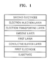
- The OLED may include at least one layer selected from the group consisting of a conductive buffer layer, a hole injection layer (HIL), a HTL, an emissive layer (EML), a hole blocking layer (HBL), an ETL, and an electron injection layer (EIL) between the first electrode and the second electrode. For example, as illustrated in
Figure 1 , the OLED may have a structure in which a substrate, a first electrode, a conductive buffer layer, a first layer which functions as a HTL, an EML, an ETL, an EIL, and a second electrode are sequentially stacked. - The OLED may comprise a substrate; a first electrode; a second electrode; and a first layer comprising a polymer disposed between the first and second electrodes; wherein the polymer is represented by Formula 6 or Formula 7 below:


- The polymer may have an average weight molecular weight (Mw) of from about 10,000 through about 200,000.
- Hereinafter, a structure of the OLED and a method of manufacturing the OLED according to an embodiment will be described with reference to
Figure 1 . - The substrate, which may be any substrate that is used in conventional organic light-emitting devices, may be a glass substrate or a transparent plastic substrate with excellent mechanical strength, thermal stability, transparency, surface smoothness, ease of handling, and waterproofness.
- The first electrode may be formed by depositing or sputtering a material that is used to form the first electrode on the substrate. When the first electrode constitutes an anode, the material used to form the first electrode may be a high work-function material so as to facilitate hole injection. The first electrode may be a reflective electrode or a transmission electrode. Transparent and conductive materials such as ITO, IZO, SnO2, and ZnO may be used to form the first electrode. Alternatively, the first electrode may be formed using magnesium (Mg), aluminum (Al), aluminum-lithium (Al-Li), calcium (Ca), magnesium-indium (Mg-In), magnesium-silver (Mg-Ag), or the like.
- The conductive buffer layer may be disposed on the first electrode. The conductive buffer layer may be formed by spin coating, casting, Langmuir Blodgett (LB) deposition, or the like.
- When the conductive buffer layer is formed using spin coating, coating conditions may vary according to a compound that is used to form the conductive buffer layer and the structure and thermal properties of the conductive buffer layer to be formed. For example, the coating conditions may include a coating speed of about 2000 rpm to about 5000 rpm, and a thermal treatment temperature of about 80°C to about 200°C, wherein the thermal treatment is for removing a solvent after coating.
- Examples of a material for the conductive buffer layer include polyaniline/dodecylbenzenesulfonic acid (Pani/DBSA), poly(3,4-ethylenedioxythiophene)/poly(4-styrenesulfonate) (PEDOT/PSS), polyaniline/camphor sulfonic acid (Pani/CSA), and (polyaniline)/poly (4-styrene- sulfonate) (PANI/PSS), but are not limited thereto.
- The thickness of the conductive buffer layer may be from about 100 Å to about 10000 Å, for example, the thickness of the conductive buffer layer may be from about 100 Å to about 1000 Å. When the thickness of the conductive buffer layer is within this range, the HIL may have an excellent hole injecting ability without a substantial increase in a driving voltage.
- Although not illustrated in
Figure 1 , an HIL may further be included between the conductive buffer layer and the substrate or on the conductive buffer layer. - The HIL may be formed by vacuum deposition, spin coating, casting, LB deposition, or the like.
- When the HIL is formed by vacuum deposition, vacuum deposition conditions may vary according to a compound that is used to form the HIL and the desired structure and thermal properties of the HIL to be formed. In general, however, the vacuum deposition may be performed at a deposition temperature of about from 100°C to about 500°C, under a pressure of from about 10-8 torr to about 10-3 torr, and at a deposition speed of from about 0.01 Å/sec to about 100 Å/sec.
- When the HIL is formed by spin coating, conditions for the spin coating may vary according to a compound that is used to form the HIL, and the desired structure and thermal properties of the HIL to be formed; however, the conditions may be selected from the coating conditions for the conductive buffer layer.
- The HIL may be formed of any material that is commonly used to form an HIL. Examples of the material that can be used to form the HIL include N,N'-diphenyl-N,N'-bis-[4-(phenyl-m-tolyl-amino)-phenyl]-biphenyl-4,4'-diamine (DNTPD), a phthalocyanine compound such as copperphthalocyanine, 4,4',4"-tris (3-methylphenylphenylamino) triphenylamine (m-MTDATA), TDATA, 2T-NATA, but are not limited thereto.


- The thickness of the HIL may be from about 100 Å to about 10000 Å, for example, the thickness of the HIL may be from about 100 Å to about 1000 Å. When the thickness of the HIL is within this range, the HIL may have an excellent hole injecting ability without a substantial increase in a driving voltage.
- A first layer including the polymer represented by Formula 1 may be formed as an HTL on the conductive buffer layer (or on the HIL, if HIL is formed) by vacuum deposition, spin coating, casting, LB deposition, or the like. Conditions for forming the first layer may be selected among, for example, the coating conditions for the conductive buffer layer.
- The thickness of the HTL including the polymer represented by Formula 1 may be from about 50 Å to about 1000 Å, and for example, the thickness of the HTL including the polymer represented by Formula 1 may be from about 100 Å to about 800 Å. When the thickness of the HTL is within the range described above, the HTL may have excellent hole transporting ability without a substantial increase in driving voltage.
- Then, an EML may be formed on the HTL including the polymer represented by Formula 1 by vacuum deposition, spin coating, casting, LB deposition, or the like. When the EML is formed by vacuum deposition or spin coating, the conditions for deposition and coating may be similar to those for the formation of the conductive buffer layer or the HIL, although the conditions for deposition and coating may vary according to the material that is used to form the EML.
- The EML may be formed of a light emitting material or a combination of a host and a dopant. Examples of the host include Alq3, 4,4'-N,N'- dicarbazole-biphenyl (CBP), poly(n-vinylcarbazole) (PVK), 9,10-di(naphthalene-2-yl)anthracene (ADN), TCTA, 1,3,5-tris(N-phenylbenzimidazole-2-yl)benzene (TPBI), 3-tert-butyl-9,10-di-2-naphthylanthracene (TBADN), E3, and distyrylarylene (DSA), but are not limited thereto.


- Examples of known red dopants include PtOEP, Ir(piq)3, and Btp2Ir(acac), but are not limited thereto.

- Also, examples of green dopants include Ir(ppy)3 (ppy = phenylpyridine), Ir(ppy)2(acac), and Ir(mpyp)3, but are not limited thereto.

- Examples of blue dopants include F2Irpic, (F2ppy)2Ir(tmd), Ir(dfppz)3, ter-fluorene, 4,4'-bis(4-diphenylaminostyryl)biphenyl (DPAVBi), and 2,5,8,11-tetra-t-butyl pherylene (TBPe), but are not limited thereto.


- When the EML include a host and a dopant, the content of the dopant may be from about 0.01 to about 15 parts by weight based on 100 parts by weight of the host, but is not limited thereto.
- The thickness of the EML may be from about 100 Å to about 1000 Å, and for example, the thickness of the EML may be from about 200 Å to about 600 Å. When the thickness of the EML is within this range, the EML may have excellent light emitting ability without a substantial increase in a driving voltage.
- An HBL may be formed between the HTL and the EML using vacuum deposition, spin coating, casting, LB deposition, or the like, to prevent diffusion of triplet excitons or holes into an ETL when a phosphorescent dopant is used to form the EML. When the HBL is formed using vacuum deposition or spin coating, the conditions for deposition and coating may be similar to those for the formation of the conductive buffer layer or the HIL, although the conditions for deposition and coating may vary according to the material that is used to form the HBL. Any material that is commonly used to form a HBL may be used. Examples of materials for forming the HBL include an oxadiazole derivative, a triazole derivative, and a phenanthroline derivative, but are not limited thereto.
- The thickness of the HBL may be from about 50 Å to about 1000 Å, and for example, the thickness of the HBL may be from about 100 Å to about 300 Å. When the thickness of the HBL is within this range, the HBL may have an excellent hole blocking ability without a substantial increase in a driving voltage.
- Then, an ETL may be formed on the EML by vacuum deposition, spin coating, casting, or the like. When the ETL is formed by vacuum deposition or spin coating, the deposition and coating conditions may be similar to those for formation of the conductive buffer layer or the HIL, although the deposition and coating conditions may vary according to a compound that is used to form the ETL. A material that is used to form the ETL may be a material that can stably transport electrons injected from the electron injecting electrode (cathode) and any known material may be used. Examples of materials for forming the ETL include a quinoline derivative, tris(8-quinolinorate)aluminum (Alq3), TAZ, and Balq, beryllium bis(benzoquinolin-10-olate: Bebq2), but are not limited thereto.

- The thickness of the ETL may be from about 100 Å to about 1000 Å, and for example, the thickness of the ETL may be from about 150 Å to about 500 Å. When the thickness of the ETL is within this range, the ETL may have satisfactory electron transporting ability without a substantial increase in a driving voltage.
- An EIL may be formed on the ETL. The EIL may be formed of any material allowing electrons to be easily injected from the cathode.
- Examples of materials for forming the EIL include LiF, NaCl, CsF, Li2O, and BaO, which are known in the art. Deposition and coating conditions for forming the EIL are similar to those for formation of the HIL, although the deposition and coating conditions may vary according to a material that is used to form the EIL.
- The thickness of the EIL may be from about 1 Å to about 100 Å, for example, the thickness of the EIL may be from about 3 Å to about 90 Å. When the thickness of the EIL is within this range, the EIL may have satisfactory electron injection ability without a substantial increase in a driving voltage.
- A second electrode is formed on the EIL. The second electrode may be a cathode that is an electron injection electrode. A metal for forming the second electrode may be a metal, an alloy, an electro-conductive compound, or mixtures thereof that respectively have a low work function. The second electrode may be formed of lithium (Li), magnesium (Mg), aluminum (Al), aluminum (Al)-lithium (Li), calcium (Ca), magnesium (Mg)-indium (In), magnesium (Mg)-silver (Ag), or the like, and may be formed as a thin film type transmission electrode. In addition, the transmission electrode may be formed of ITO or IZO to manufacture a top-emission type light-emitting device.
- The method of manufacturing an OLED including the first layer including the polymer represented by Formula 1 which functions as a HTL has been described above; however, the first layer including the polymer represented by Formula 1 may also function not only as an HTL but also an EML, an ETL, or the like, according to the substituent included in the first layer.
- In an OLED according to another embodiment, in which the first layer functions as an EML and/or ETL, the HTL may be formed by using known hole transporting materials. Examples of the hole transporting material include: a carbazole derivative such as N-phenylcarbazole or polyvinylcarbazole; an amine derivative having an aromatic condensation ring, such as N,N'-bis(3-methylphenyl)-N,N'-diphenyl-[1,1-biphenyl]-4,4'-diamine (TPD) illustrated below or N,N'-di(naphthalene-1-yl)-N,N'-diphenyl benzidine (α-NPD) illustrated below; and a triphenylamine-based material, such as 4,4',4"-tris(N-carbazolyl)triphenylamine (TCTA). Among these materials, TCTA may not only transport holes but also inhibit excitons from being diffused into the EML.

- Hereinafter, an OLED according to an embodiment will be described in detail with reference to synthesis examples and exemplary embodiments below. However, these examples are not intended to limit the purpose and scope of the present embodiments below.
- Compound (e) (phenoxazine dimer) was synthesized through Reaction Scheme 2 below:

- 50 g (0.29 mole) of 4-bromophenol was dissolved in acetone (500 ml), and 48.4 g (0.35 mole) of K2CO3was added thereto. Next, 73.3 g (0.38 mole) of 1-bromooctane was added to the mixture and refluxed for 24 hours. After the reaction was completed, the resultant mixture was extracted by using a solution containing water and CHCl3 in a volume ratio of 2:1, to remove K2CO3, thereby obtaining an organic layer. The organic layer was concentrated by drying with MgSO4, and silica gel column chromatography was performed thereon by using hexane as an eluant. The obtained effluent was distilled under a reduced pressure to remove unreacted 1-bromooctane, thereby obtaining 80 g of Compound (a) (yield: 96%).
- 18 g (64 mmol) of Compound (a), 10 g (54 mmol) of phenoxazine, 7.4 g (77 mmol) of sodium tert-butoxide, 0.61g (1.1 mmol) of Pd2(dba)3,[Tris(dibenzylidine acetone) dipalladium(0))], and 0.22 g of (1.1 mmol) of tri(tert-butyl)phosphine were dissolved in 250 ml of xylene, and reacted at 80°C for 12 hours. After the reaction was completed, the resultant mixture was cooled to room temperature, and then 200 ml of distilled water was added thereto and extraction was performed using xylene and water in a volume ratio of 1:1, thereby obtaining an organic layer. The organic layer was concentrated by drying using MgSO4 and silica gel column chromatography was performed thereon by using a solution containing toluene and hexane in a volume ratio of 1:2. The effluent was concentrated and dried, thereby obtaining 18.5 g (yield: 88 %) of Compound (b).
- 5 g (13 mmol) of Compound (b) was dissolved in 150 ml of CHCl3, and bromine in an equivalent amount with respect to Compound (b) was slowly added thereto while the temperature was maintained at 0 °C. When removal of the starting material was identified through thin layer chromatography (TLC), addition of the bromine to the mixture was stopped, and the reactant mixture was stirred for 10 minutes and then the reaction was stopped. A small amount of acetone was added to the reactant mixture to quench bromine, and extraction was performed thereon using a solution containing water and CHCl3 in a volume ratio of 2:1, thereby obtaining an organic layer. The organic layer was concentrated by drying using MgSO4, and re-precipitated in MeOH, thereby obtaining 6 g (yield: 85%) of Compound (c). A structure of Compound (c) was identified by 1H-NMR:
- 1H-NMR (300MHz, CDCl3): δ0.91(m, 6H), δ1.45(m 8H), δ1.82(m 1H), δ3.89(d, 2H), δ5.82(d, 2H), δ6.5∼7.5(m, 9H).
- A Schlenk flask was vacuumized and refluxed under a nitrogen atmosphere several times to completely eliminate water, and then 880 mg (3.2 mmol) of bis 1,5-cyclooctadiene nickel and 500 mg (3.2 mmol) of bipyridal were input in a glove box, and the flask was vacuumized and refluxed under a nitrogen atmosphere again several times. Next, under a nitrogen atmosphere, 10 ml of anhydrate dimethylfurane (DMF), 346 mg (3.2 mmol) of 1,5-cyclooctadiene (COD), and 10 ml of anhydrate toluene were added thereto. After stirring at 80°C for 30 minutes, 0.746 g (0.16 mmol) of Compound (c) diluted in 10 ml of toluene was added thereto. Next, 10 ml of toluene was added thereto while removing materials attached to walls of the flask therewith, and the resultant solution was stirred at 80°C for 2 hours. After the stirring was completed, the temperature of the reaction solution was reduced to 60°C, and then the reaction solution was poured into a solution of HCl:acetone:methanol (1:1:2) to form precipitation. The precipitation was dissolved in chloroform, and then an organic layer was dried using MgSO4 and concentrated, and silica gel column chromatography was performed thereon by using a solution containing toluene and hexane in a volume ratio of 3:7 as an eluant. The effluent was concentrated and dried, thereby obtaining 0.5 g of Compound (d).
- 1H-NMR (300MHz, CDCl3): δ0.93 (12H), δ1.4 (16H), δ1.80 (2H), δ3.92 (4H), δ5.85 (4H), δ6.3∼7.7 (18H)
- 0.5 g (0.647 mmol) of Compound (d) was melted in CHCl3, and 2.1 equivalent of bromine was slowly added thereto while maintaining a temperature at 0°C. The reactant mixture was stirred for 10 minutes and then the reaction was stopped. By adding a small amount of acetone to the reactant mixture, the bromine was quenched and then extracted by using a solution containing water and chloroform in a volume ratio of 2:1, thereby obtaining an organic layer. The organic layer was concentrated by drying using anhydrate magnesium sulfate, and re-precipitated in methanol, thereby obtaining 580 mg (yield: 96%) of Compound (e).
- 1H NMR (300MHz, CDCl3) δ0.93(12H), δ1.48(16H), δ1.80(2H), δ3.92(4H), δ5.92(4H), δ6.2∼7.9(18H)
- Polymer 1 was synthesized through Reaction Scheme 3 below:

- Polymer 2 was synthesized according to Reaction Scheme 4 below:

- Polymer 3 was synthesized according to Reaction Scheme 5 below:

- As an anode, a 15Ω/cm2 (1200Å) ITO glass substrate by Corning was cut to a size of 50 mm × 50 mm × 0.7 mm, ultrasonically washed with isopropyl alcohol and pure water for 5 minutes each, and then washed with UV ozone for 30 minutes. Next, PEDOT:PSS (poly(3,4-ethylenedioxythiophene) poly(styrenesulfonate, AI4083, available by H. C. Stark) was coated on the ITO in the ITO glass with a thickness of about 600Å, and was heated at 200°C for about 20 minutes, thereby forming a conductive buffer layer. Next, 5 mg of Polymer 1 prepared according to Synthesis Example 2 was dissolved in 1 ml of toluene to obtain a polymer solution, and the polymer solution was filtered using a 0.2 µm filter before spin coating. A resultant obtained by the filtering was spin-coated on the conductive buffer layer, and then heated at 200°C for 10 minutes, thereby forming a hole transporting layer (HTL). A thickness of the HTL may be adjusted to be about 300Å by adjusting concentration and spin speed of the polymer solution. 97 wt% of DSA as a host and 3 wt% of TBPe as a dopant were vacuum-deposited on the HTL to form an EML with a thickness of 300Å. Next, Alq3 was vacuum-deposited on the EML to form an ETL having a thickness of 200Å. LiF having a thickness of 80Å and Al having a thickness of 3000Å were sequentially vacuum-deposited on the ETL to form an EIL and a cathode to manufacture an OLED. The thickness of layers and the growth speed thereof during the deposition are adjusted by using a crystal sensor.
- An OLED was manufactured in the same manner as Example 1 except that Polymer 2 of Synthesis Example 3 was used instead of Polymer 1 to form an HTL of Example 1.
- An OLED was manufactured in the same manner as Example 1 except that Polymer 3 of Synthesis Example 4 was used instead of Polymer 1 to form an HTL of Example 1.
- An OLED was manufactured in the same manner as Example 1 except that an EML was formed on the conductive buffer layer without forming the HTL in Example 1.
- An OLED was manufactured in the same manner as Example 1 except that Polymer A below was used instead of Polymer 1 to form an HTL in Example 1. Polymer A was analyzed by GPC. As a result, a Mw of Polymer A was 58,000 and a dispersion degree of Polymer A was 2.7.

- Luminance (cd/m2), efficiency (cd/A), and lifetime of the OLEDs of Example 1, Example 2, Example 3, Comparative Example 1, and Comparative Example 2 were measured by using a PR650 (Spectroscan) Source Measurement Unit and results thereof are shown in Table 1. The lifetime was evaluated by measuring the time when the initial luminance of 100cd/m2 is reduced by half.
Table 1 HTL Efficiency (cd/A) Half lifetime (time)@100 cd/m2 Example 1 Polymer 1 4.39 2000 Example 2 Polymer 2 4.76 2400 Example 3 Polymer 3 3.9 2200 Comparative Example 1 HTL is not formed. 1.32 13 Comparative Example 2 Polymer A 3.16 1800 - As shown in Table 1, the OLEDs of Examples 1 through 3 have better efficiency and lifetime characteristics than the OLED of Comparative Examples 1 and 2.
- While the present invention has been described in connection with certain exemplary embodiments thereof, it is to be understood that the invention is not limited to the disclosed embodiments, but, on the contrary, is intended to cover various modifications and equivalent arrangements included within the scope of the appended claims.
Claims (15)
- A polymer represented by Formula 1 below:

wherein X1 and X2 are each independently selected from the group consisting of -O-, -S-, - N(Z2)-, and -C(Z3)(Z4)-, and
wherein R1, R2, Z1, Z2, Z3, and Z4 are each independently selected from the group consisting of hydrogen, a substituted or unsubstituted C1-C30 alkyl group, a substituted or unsubstituted C2-C30 alkenyl group, a substituted or unsubstituted C2-C30 alkynyl group, a substituted or unsubstituted C1-C30 alkoxy group, a substituted or unsubstituted C3-C12 cycloalkyl group, a substituted or unsubstituted C3-C12 cycloheteroalkyl group, a substituted or unsubstituted C5-C30 aryl group, and a substituted or unsubstituted C4-C30 heteroaryl group, and
wherein a and b are independently an actual number from 0.01 to 0.99, wherein a+b=1. - The polymer of claim 1, wherein Q1 is selected from the group consisting of a substituted or unsubstituted C5-C14 arylene group, a substituted or unsubstituted C4-C14 heteroarylene group, a substituted or unsubstituted C2-C10 alkenylene group, and a group represented by -N(Z1)-;
wherein Z1 is selected from the group consisting of hydrogen, a substituted or unsubstituted C1-C30 alkyl group, a substituted or unsubstituted C2-C30 alkenyl group, a substituted or unsubstituted C2-C30 alkynyl group, a substituted or unsubstituted C1-C30 alkoxy group, a substituted or unsubstituted C3-C12 cycloalkyl group, a substituted or unsubstituted C3-C12 cycloheteroalkyl group, a substituted or unsubstituted C5-C30 aryl group, and a substituted or unsubstituted C4-C30 heteroaryl group; and
Formulae 2a through 2x below:
 wherein in Formulae 2a through 2x, T1 through T4 are each independently selected from the group consisting of hydrogen, a halogen atom, a cyano group, a hydroxyl group, a C1-C10 alkyl group, a C1-C10 alkoxy group, a C2-C10 alkenyl group, a C5-C14 aryl group, a C4-C14 heteroaryl group, and a group represented by -N(Z5)(Z6);p, q, r, and s are each independently an integer from 0 through 4;Z5 and Z6 are each independently selected from the group consisting of hydrogen, a halogen atom, a cyano group, a hydroxyl group, a C1-C10 alkyl group, a C1-C10 alkoxy group, a C2-C10 alkenyl group, a C5-C14 aryl group, and a C4-C14 heteroaryl group; andp groups of T1 in -(T1)p are identical to or different from each other, q groups of T2 in -(T2)q are identical to or different from each other, r groups of T3 in -(T3)r are identical to or different from each other, and s groups of T4 in -(T4)s are identical to or different from each other.
 - The polymer of claim 2, wherein T1 through T4 are each independently selected from the group consisting of hydrogen, a C1-C10 alkyl group, a C1-C10 alkoxy group, a phenyl group, a naphthyl group, and a group represented by -N(Z5)(Z6), and Z5 and Z6 are each independently selected from the group consisting of hydrogen, a C1-C10 alkyl group, a C1-C10 alkoxy group, a phenyl group, and a naphthyl group.
- The polymer of any one of the preceding claims, wherein n is 1, 2, 3, 4, 5, or 6.
- The polymer of claim 1, wherein Ar1 is each independently selected from the group consisting of Formulae 2a through 2x and Formulae 3a through 31 below:
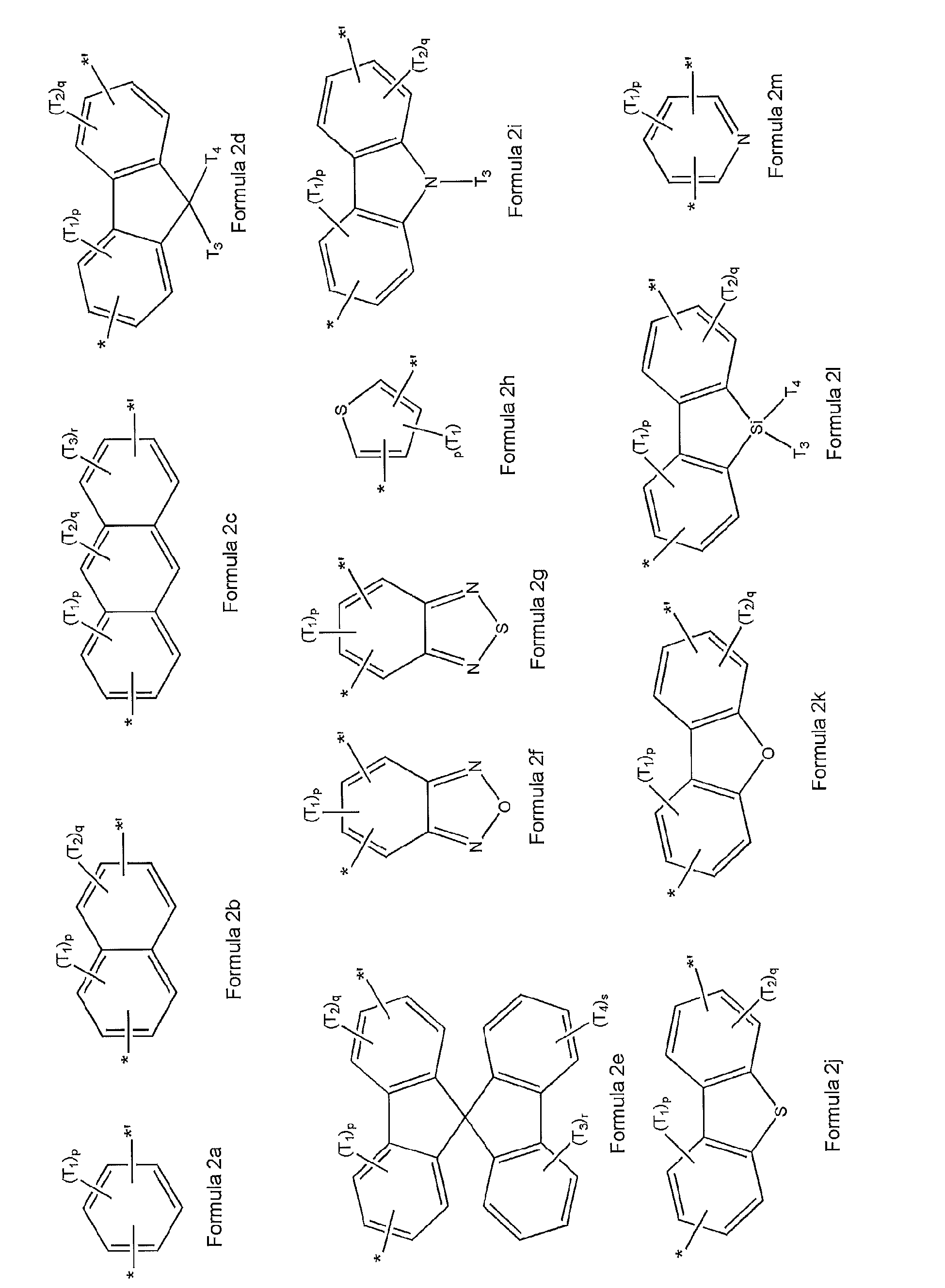

 wherein in Formulae 2a through 2x and Formulae 3a through 31, T1 through T4 are each independently selected from the group consisting of hydrogen, a halogen atom, a cyano group, a hydroxyl group, a C1-C10 alkyl group, a C1-C10 alkoxy group, a C2-C10 alkenyl group, a C5-C14 aryl group, a C4-C14 heteroaryl group, and a group represented by -N(Z5)(Z6);Z5 and Z6 are each independently selected from the group consisting of hydrogen, a halogen atom, a cyano group, a hydroxyl group, a C1-C10 alkyl group, a C1-C10 alkoxy group, a C2-C10 alkenyl group, a C5-C14 aryl group, and a C4-C14 heteroaryl group;p, q, r, and s are each independently an integer from 0 to 4; andp groups of T1 in -(T1)p are identical to or different from each other, q groups of T2 in -(T2)q are identical to or different from each other, r groups of T3 in -(T3)r are identical to or different from each other, and s groups of T4 in -(T4)s are identical to or different from each other.
 - The polymer of claim 1, wherein Ar1 is represented by Formula 2d, and T1 and T2 of Formula 2d are hydrogen, and T3 and T4 are each independently selected from the group consisting of hydrogen, a C1-C10 alkyl group, and a C1-C10 alkoxy group:

- The polymer of claim 1, wherein Ar1 is represented by Formula 2e below, and T1 and T2 of Formula 2e are hydrogen, and T3 and T4 are each independently selected from the group consisting of hydrogen, a C1-C10 alkyl group, and a C1-C10 alkoxy group:

- The polymer of any one of the preceding claims, wherein each of X1 and X2 are -O-.
- The polymer of any one of the preceding claims, wherein R1 and R2 are each independently selected from the group consisting of a C5-C14 aryl group; a C4-C14 heteroaryl group; a C5-C14 aryl group substituted with at least one selected from the group consisting of a halogen atom, a hydroxyl group, a cyano group, a C1-C10 alkyl group, a C1-C10 alkoxy group, and a C5-C14 aryl group; and a C4-C14 heteroaryl group substituted with at least one selected from the group consisting of a halogen atom, a hydroxyl group, a cyano group, a C1-C10 alkyl group, a C1-C10 alkoxy group, and a C5-C14 aryl group.
- The polymer of any one of the preceding claims, wherein R1 and R2 are each represented by Formula 4a below:

- The polymer of any one of the preceding claims, wherein a and b are each independently an actual number from 0.3 to 0.7.
- The polymer of any one of the preceding claims, wherein the polymer is represented by Formula 6 or Formula 7 below:

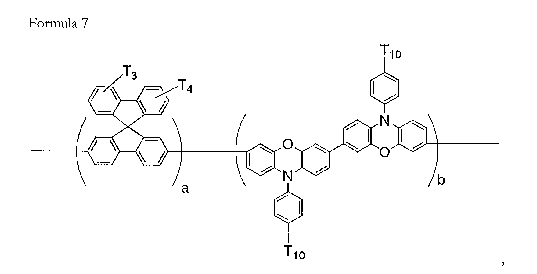
- The polymer of any one of the preceding claims, wherein the polymer has an average weight molecular weight (Mw) of from about 10,000 through about 200,000.
- The polymer of any one of the preceding claims, wherein the polymer has polydispersion index (PDI) of from about 1.5 through about 5.
- An organic light emitting device (OLED) comprising: a substrate; a first electrode; a second electrode; and a first layer comprising a polymer according to claim 1 and disposed between the first and second electrodes.
Applications Claiming Priority (1)
| Application Number | Priority Date | Filing Date | Title |
|---|---|---|---|
| KR1020090096394A KR101137386B1 (en) | 2009-10-09 | 2009-10-09 | Polymer and organic light emitting diode comprising the same |
Publications (2)
| Publication Number | Publication Date |
|---|---|
| EP2308911A2 true EP2308911A2 (en) | 2011-04-13 |
| EP2308911A3 EP2308911A3 (en) | 2012-02-01 |
Family
ID=43608315
Family Applications (1)
| Application Number | Title | Priority Date | Filing Date |
|---|---|---|---|
| EP10186431A Withdrawn EP2308911A3 (en) | 2009-10-09 | 2010-10-04 | Polymer and organic light-emitting device including the same |
Country Status (5)
| Country | Link |
|---|---|
| US (1) | US8987709B2 (en) |
| EP (1) | EP2308911A3 (en) |
| JP (1) | JP5432106B2 (en) |
| KR (1) | KR101137386B1 (en) |
| CN (1) | CN102040728B (en) |
Cited By (2)
| Publication number | Priority date | Publication date | Assignee | Title |
|---|---|---|---|---|
| WO2017028941A1 (en) * | 2015-08-14 | 2017-02-23 | Merck Patent Gmbh | Phenoxazine derivatives for organic electroluminescent devices |
| US20200089070A1 (en) * | 2015-06-19 | 2020-03-19 | Satoshi Yamamoto | Electrochromic compound, electrochromic composition, and electrochromic display element |
Families Citing this family (9)
| Publication number | Priority date | Publication date | Assignee | Title |
|---|---|---|---|---|
| JP6182145B2 (en) | 2011-09-28 | 2017-08-16 | 住友化学株式会社 | Spirobifluorene compounds for light emitting devices |
| JP5981440B2 (en) * | 2011-10-19 | 2016-08-31 | 出光興産株式会社 | Carbazole polymer and organic electroluminescence device using the same |
| KR20140006134A (en) * | 2012-06-25 | 2014-01-16 | 가톨릭대학교 산학협력단 | Method for manufacturing organic light emitting diode and display including the organic light emitting diode |
| KR102052076B1 (en) * | 2013-06-14 | 2019-12-05 | 삼성디스플레이 주식회사 | Organic light-emitting diode |
| US10840454B2 (en) | 2013-06-14 | 2020-11-17 | Samsung Display Co., Ltd. | Organic light-emitting devices |
| US12193322B2 (en) | 2013-06-14 | 2025-01-07 | Samsung Display Co., Ltd. | Organic light-emitting devices |
| TWI615611B (en) * | 2016-12-20 | 2018-02-21 | Gas detector | |
| CN109321234B (en) * | 2018-10-19 | 2020-04-03 | 武汉华星光电半导体显示技术有限公司 | Electroluminescent material, preparation method of electroluminescent material and luminescent device |
| CN115947703A (en) * | 2022-11-30 | 2023-04-11 | 河南欧博尔光电科技有限公司 | A kind of synthetic method of the heterocyclic intermediate containing the substituent of polyhalogen |
Family Cites Families (18)
| Publication number | Priority date | Publication date | Assignee | Title |
|---|---|---|---|---|
| US6249369B1 (en) * | 1999-07-09 | 2001-06-19 | Gentex Corporation | Coupled electrochromic compounds with photostable dication oxidation states |
| DE10143353A1 (en) | 2001-09-04 | 2003-03-20 | Covion Organic Semiconductors | Conjugated polymers containing spirobifluorene units and their use |
| DE10143249A1 (en) | 2001-09-04 | 2003-03-20 | Thomas J J Mueller | Production of conjugated, bridged and directly linked phenothiazine oligomers and copolymers, useful as hole conductors in organic light emitting diodes and organic field effect transistors |
| JP3881876B2 (en) * | 2001-11-30 | 2007-02-14 | 凸版印刷株式会社 | Polymer compound and organic thin film device using the same |
| KR20030097358A (en) | 2002-06-20 | 2003-12-31 | 삼성전자주식회사 | Method for coding of signal using convolutional encoder and turbo coder based on puncturing pattern determined according to constellation |
| US6984461B2 (en) * | 2002-06-21 | 2006-01-10 | Samsung Sdi Co., Ltd. | Blue electroluminescent polymer and organic-electroluminescent device using the same |
| US6916902B2 (en) * | 2002-12-19 | 2005-07-12 | Dow Global Technologies Inc. | Tricyclic arylamine containing polymers and electronic devices therefrom |
| KR100682860B1 (en) * | 2004-01-27 | 2007-02-15 | 삼성에스디아이 주식회사 | Spirofluorene polymer and organic electroluminescent device using same |
| JP4904805B2 (en) | 2004-12-27 | 2012-03-28 | 住友化学株式会社 | Polymer compound and polymer light emitting device using the same |
| KR101202340B1 (en) * | 2005-01-21 | 2012-11-16 | 삼성디스플레이 주식회사 | Blue electroluminescent compound and organo-electroluminescent device employing the same |
| DE112006002668T5 (en) * | 2005-10-07 | 2008-08-14 | Sumitomo Chemical Company, Ltd. | Copolymer and polymeric light-emitting device using the same |
| KR101243918B1 (en) * | 2006-01-03 | 2013-03-14 | 삼성디스플레이 주식회사 | Blue electroluminescent polymer, a method for preparing the blue electroluminescent polymer and an organoelectroluminescent device employing the same |
| KR101328972B1 (en) | 2006-01-26 | 2013-11-13 | 삼성디스플레이 주식회사 | Electroluminescent Polymer And Organic-electroluminescent Device Manufactured By Using The Same |
| KR101288304B1 (en) * | 2006-01-27 | 2013-07-18 | 삼성디스플레이 주식회사 | Organic light emitting compound and organic light emitting device comprising the same |
| KR101223720B1 (en) | 2006-06-05 | 2013-01-17 | 삼성디스플레이 주식회사 | Polymer compound and organic light-emitting device employing the same |
| JP5407122B2 (en) * | 2006-08-01 | 2014-02-05 | 住友化学株式会社 | Polymer compound and polymer light emitting device |
| JP5251043B2 (en) * | 2006-09-13 | 2013-07-31 | 住友化学株式会社 | Polymer compound and polymer light emitting device |
| EP2070965A4 (en) * | 2006-09-13 | 2010-11-10 | Sumitomo Chemical Co | POLYMER COMPOUND AND POLYMER DEVICE EMITTING LIGHT |
-
2009
- 2009-10-09 KR KR1020090096394A patent/KR101137386B1/en not_active Expired - Fee Related
-
2010
- 2010-09-30 US US12/895,374 patent/US8987709B2/en active Active
- 2010-10-04 EP EP10186431A patent/EP2308911A3/en not_active Withdrawn
- 2010-10-08 JP JP2010228733A patent/JP5432106B2/en active Active
- 2010-10-09 CN CN201010503410.XA patent/CN102040728B/en active Active
Non-Patent Citations (1)
| Title |
|---|
| ANDREW C GRIMSDALE ET AL: "Synthesis of Light-Emitting Conjugated Polymers for Applications in Electroluminescent Devices", CHEMICAL REV, AMERICAN CHEMICAL SOCIETY, US, vol. 109, 1 February 2009 (2009-02-01), pages 897 - 1091, XP009133687, ISSN: 0009-2665, DOI: 10.1021/CR000013V * |
Cited By (4)
| Publication number | Priority date | Publication date | Assignee | Title |
|---|---|---|---|---|
| US20200089070A1 (en) * | 2015-06-19 | 2020-03-19 | Satoshi Yamamoto | Electrochromic compound, electrochromic composition, and electrochromic display element |
| US10935862B2 (en) * | 2015-06-19 | 2021-03-02 | Ricoh Company, Ltd. | Electrochromic compound, electrochromic composition, and electrochromic display element |
| WO2017028941A1 (en) * | 2015-08-14 | 2017-02-23 | Merck Patent Gmbh | Phenoxazine derivatives for organic electroluminescent devices |
| US11189801B2 (en) | 2015-08-14 | 2021-11-30 | Merck Patent Gmbh | Phenoxazine derivatives for organic electroluminescent devices |
Also Published As
| Publication number | Publication date |
|---|---|
| US20110084254A1 (en) | 2011-04-14 |
| CN102040728B (en) | 2016-02-17 |
| CN102040728A (en) | 2011-05-04 |
| JP2011080066A (en) | 2011-04-21 |
| US8987709B2 (en) | 2015-03-24 |
| KR101137386B1 (en) | 2012-04-20 |
| EP2308911A3 (en) | 2012-02-01 |
| JP5432106B2 (en) | 2014-03-05 |
| KR20110039109A (en) | 2011-04-15 |
Similar Documents
| Publication | Publication Date | Title |
|---|---|---|
| EP2308911A2 (en) | Polymer and organic light-emitting device including the same | |
| EP2308843B1 (en) | Condensed-cyclic compound and organic light emitting diode including organic layer containing the condensed-cyclic compound | |
| CN101656301B (en) | Organic light emitting diode employing luminescent efficiency improvement layer | |
| KR101182444B1 (en) | Organic light emitting diode comprising the same | |
| EP1921082A1 (en) | Silanylamine-based compound, method of preparing the same and organic light emitting device including organic layer comprising the silanylamine-based compound | |
| KR102079254B1 (en) | Organic light emitting diode | |
| KR102081280B1 (en) | Organic light emitting diode comprising the same | |
| EP2110373B1 (en) | Bipyridine-based compound and organic light emitting diode employing organic layer comprising the same | |
| EP2407502B1 (en) | Dendrimer and organic light-emitting device using the same | |
| KR102023028B1 (en) | Condensed compound and organic light emitting diode comprising the same | |
| KR102147840B1 (en) | Amined-basd compound and organic light emitting diode including the same | |
| US8384074B2 (en) | Heterocyclic compound and organic light-emitting device including the same | |
| KR20130016032A (en) | A carbazole-based compound and an organic light emitting diode comprising the same | |
| KR100852118B1 (en) | An imidazopyrimidine compound and an organic light emitting device comprising an organic film | |
| EP2407501B1 (en) | Dendrimer and organic light-emitting device using the same | |
| US9324953B2 (en) | Condensed-cyclic compounds and organic light-emitting diodes comprising the same | |
| EP2371878B1 (en) | Polymer compound and organic light-emitting device including the same | |
| US8455866B2 (en) | Heterocyclic compound and organic light-emitting device including the same | |
| KR20090018503A (en) | Oxadiazole derivative compound and organic light emitting device having the same | |
| KR20090053488A (en) | An organic light emitting device comprising an oxadiazole compound and an organic film including the same | |
| KR102111561B1 (en) | Organic light emitting diode |
Legal Events
| Date | Code | Title | Description |
|---|---|---|---|
| PUAI | Public reference made under article 153(3) epc to a published international application that has entered the european phase |
Free format text: ORIGINAL CODE: 0009012 |
|
| AK | Designated contracting states |
Kind code of ref document: A2 Designated state(s): AL AT BE BG CH CY CZ DE DK EE ES FI FR GB GR HR HU IE IS IT LI LT LU LV MC MK MT NL NO PL PT RO RS SE SI SK SM TR |
|
| AX | Request for extension of the european patent |
Extension state: BA ME |
|
| PUAL | Search report despatched |
Free format text: ORIGINAL CODE: 0009013 |
|
| AK | Designated contracting states |
Kind code of ref document: A3 Designated state(s): AL AT BE BG CH CY CZ DE DK EE ES FI FR GB GR HR HU IE IS IT LI LT LU LV MC MK MT NL NO PL PT RO RS SE SI SK SM TR |
|
| AX | Request for extension of the european patent |
Extension state: BA ME |
|
| RIC1 | Information provided on ipc code assigned before grant |
Ipc: H01L 51/00 20060101ALI20111229BHEP Ipc: H01B 1/00 20060101ALI20111229BHEP Ipc: C08G 73/00 20060101ALI20111229BHEP Ipc: C08G 61/00 20060101AFI20111229BHEP |
|
| 17P | Request for examination filed |
Effective date: 20120517 |
|
| RAP1 | Party data changed (applicant data changed or rights of an application transferred) |
Owner name: SAMSUNG DISPLAY CO., LTD. |
|
| 17Q | First examination report despatched |
Effective date: 20140220 |
|
| RAP1 | Party data changed (applicant data changed or rights of an application transferred) |
Owner name: SAMSUNG DISPLAY CO., LTD. |
|
| STAA | Information on the status of an ep patent application or granted ep patent |
Free format text: STATUS: EXAMINATION IS IN PROGRESS |
|
| STAA | Information on the status of an ep patent application or granted ep patent |
Free format text: STATUS: THE APPLICATION IS DEEMED TO BE WITHDRAWN |
|
| 18D | Application deemed to be withdrawn |
Effective date: 20191206 |