EP2308811A1 - Hybred polymer CVI composites - Google Patents
Hybred polymer CVI composites Download PDFInfo
- Publication number
- EP2308811A1 EP2308811A1 EP10251648A EP10251648A EP2308811A1 EP 2308811 A1 EP2308811 A1 EP 2308811A1 EP 10251648 A EP10251648 A EP 10251648A EP 10251648 A EP10251648 A EP 10251648A EP 2308811 A1 EP2308811 A1 EP 2308811A1
- Authority
- EP
- European Patent Office
- Prior art keywords
- composite
- preform
- ceramic
- cvi
- density
- Prior art date
- Legal status (The legal status is an assumption and is not a legal conclusion. Google has not performed a legal analysis and makes no representation as to the accuracy of the status listed.)
- Withdrawn
Links
Images

Classifications
-
- C—CHEMISTRY; METALLURGY
- C04—CEMENTS; CONCRETE; ARTIFICIAL STONE; CERAMICS; REFRACTORIES
- C04B—LIME, MAGNESIA; SLAG; CEMENTS; COMPOSITIONS THEREOF, e.g. MORTARS, CONCRETE OR LIKE BUILDING MATERIALS; ARTIFICIAL STONE; CERAMICS; REFRACTORIES; TREATMENT OF NATURAL STONE
- C04B35/00—Shaped ceramic products characterised by their composition; Ceramics compositions; Processing powders of inorganic compounds preparatory to the manufacturing of ceramic products
- C04B35/71—Ceramic products containing macroscopic reinforcing agents
- C04B35/78—Ceramic products containing macroscopic reinforcing agents containing non-metallic materials
- C04B35/80—Fibres, filaments, whiskers, platelets, or the like
-
- C—CHEMISTRY; METALLURGY
- C04—CEMENTS; CONCRETE; ARTIFICIAL STONE; CERAMICS; REFRACTORIES
- C04B—LIME, MAGNESIA; SLAG; CEMENTS; COMPOSITIONS THEREOF, e.g. MORTARS, CONCRETE OR LIKE BUILDING MATERIALS; ARTIFICIAL STONE; CERAMICS; REFRACTORIES; TREATMENT OF NATURAL STONE
- C04B35/00—Shaped ceramic products characterised by their composition; Ceramics compositions; Processing powders of inorganic compounds preparatory to the manufacturing of ceramic products
- C04B35/515—Shaped ceramic products characterised by their composition; Ceramics compositions; Processing powders of inorganic compounds preparatory to the manufacturing of ceramic products based on non-oxide ceramics
- C04B35/56—Shaped ceramic products characterised by their composition; Ceramics compositions; Processing powders of inorganic compounds preparatory to the manufacturing of ceramic products based on non-oxide ceramics based on carbides or oxycarbides
- C04B35/565—Shaped ceramic products characterised by their composition; Ceramics compositions; Processing powders of inorganic compounds preparatory to the manufacturing of ceramic products based on non-oxide ceramics based on carbides or oxycarbides based on silicon carbide
-
- C—CHEMISTRY; METALLURGY
- C04—CEMENTS; CONCRETE; ARTIFICIAL STONE; CERAMICS; REFRACTORIES
- C04B—LIME, MAGNESIA; SLAG; CEMENTS; COMPOSITIONS THEREOF, e.g. MORTARS, CONCRETE OR LIKE BUILDING MATERIALS; ARTIFICIAL STONE; CERAMICS; REFRACTORIES; TREATMENT OF NATURAL STONE
- C04B35/00—Shaped ceramic products characterised by their composition; Ceramics compositions; Processing powders of inorganic compounds preparatory to the manufacturing of ceramic products
- C04B35/515—Shaped ceramic products characterised by their composition; Ceramics compositions; Processing powders of inorganic compounds preparatory to the manufacturing of ceramic products based on non-oxide ceramics
- C04B35/56—Shaped ceramic products characterised by their composition; Ceramics compositions; Processing powders of inorganic compounds preparatory to the manufacturing of ceramic products based on non-oxide ceramics based on carbides or oxycarbides
- C04B35/565—Shaped ceramic products characterised by their composition; Ceramics compositions; Processing powders of inorganic compounds preparatory to the manufacturing of ceramic products based on non-oxide ceramics based on carbides or oxycarbides based on silicon carbide
- C04B35/571—Shaped ceramic products characterised by their composition; Ceramics compositions; Processing powders of inorganic compounds preparatory to the manufacturing of ceramic products based on non-oxide ceramics based on carbides or oxycarbides based on silicon carbide obtained from Si-containing polymer precursors or organosilicon monomers
-
- C—CHEMISTRY; METALLURGY
- C04—CEMENTS; CONCRETE; ARTIFICIAL STONE; CERAMICS; REFRACTORIES
- C04B—LIME, MAGNESIA; SLAG; CEMENTS; COMPOSITIONS THEREOF, e.g. MORTARS, CONCRETE OR LIKE BUILDING MATERIALS; ARTIFICIAL STONE; CERAMICS; REFRACTORIES; TREATMENT OF NATURAL STONE
- C04B35/00—Shaped ceramic products characterised by their composition; Ceramics compositions; Processing powders of inorganic compounds preparatory to the manufacturing of ceramic products
- C04B35/515—Shaped ceramic products characterised by their composition; Ceramics compositions; Processing powders of inorganic compounds preparatory to the manufacturing of ceramic products based on non-oxide ceramics
- C04B35/58—Shaped ceramic products characterised by their composition; Ceramics compositions; Processing powders of inorganic compounds preparatory to the manufacturing of ceramic products based on non-oxide ceramics based on borides, nitrides, i.e. nitrides, oxynitrides, carbonitrides or oxycarbonitrides or silicides
- C04B35/584—Shaped ceramic products characterised by their composition; Ceramics compositions; Processing powders of inorganic compounds preparatory to the manufacturing of ceramic products based on non-oxide ceramics based on borides, nitrides, i.e. nitrides, oxynitrides, carbonitrides or oxycarbonitrides or silicides based on silicon nitride
-
- C—CHEMISTRY; METALLURGY
- C04—CEMENTS; CONCRETE; ARTIFICIAL STONE; CERAMICS; REFRACTORIES
- C04B—LIME, MAGNESIA; SLAG; CEMENTS; COMPOSITIONS THEREOF, e.g. MORTARS, CONCRETE OR LIKE BUILDING MATERIALS; ARTIFICIAL STONE; CERAMICS; REFRACTORIES; TREATMENT OF NATURAL STONE
- C04B35/00—Shaped ceramic products characterised by their composition; Ceramics compositions; Processing powders of inorganic compounds preparatory to the manufacturing of ceramic products
- C04B35/515—Shaped ceramic products characterised by their composition; Ceramics compositions; Processing powders of inorganic compounds preparatory to the manufacturing of ceramic products based on non-oxide ceramics
- C04B35/58—Shaped ceramic products characterised by their composition; Ceramics compositions; Processing powders of inorganic compounds preparatory to the manufacturing of ceramic products based on non-oxide ceramics based on borides, nitrides, i.e. nitrides, oxynitrides, carbonitrides or oxycarbonitrides or silicides
- C04B35/584—Shaped ceramic products characterised by their composition; Ceramics compositions; Processing powders of inorganic compounds preparatory to the manufacturing of ceramic products based on non-oxide ceramics based on borides, nitrides, i.e. nitrides, oxynitrides, carbonitrides or oxycarbonitrides or silicides based on silicon nitride
- C04B35/589—Shaped ceramic products characterised by their composition; Ceramics compositions; Processing powders of inorganic compounds preparatory to the manufacturing of ceramic products based on non-oxide ceramics based on borides, nitrides, i.e. nitrides, oxynitrides, carbonitrides or oxycarbonitrides or silicides based on silicon nitride obtained from Si-containing polymer precursors or organosilicon monomers
-
- C—CHEMISTRY; METALLURGY
- C04—CEMENTS; CONCRETE; ARTIFICIAL STONE; CERAMICS; REFRACTORIES
- C04B—LIME, MAGNESIA; SLAG; CEMENTS; COMPOSITIONS THEREOF, e.g. MORTARS, CONCRETE OR LIKE BUILDING MATERIALS; ARTIFICIAL STONE; CERAMICS; REFRACTORIES; TREATMENT OF NATURAL STONE
- C04B35/00—Shaped ceramic products characterised by their composition; Ceramics compositions; Processing powders of inorganic compounds preparatory to the manufacturing of ceramic products
- C04B35/622—Forming processes; Processing powders of inorganic compounds preparatory to the manufacturing of ceramic products
-
- C—CHEMISTRY; METALLURGY
- C04—CEMENTS; CONCRETE; ARTIFICIAL STONE; CERAMICS; REFRACTORIES
- C04B—LIME, MAGNESIA; SLAG; CEMENTS; COMPOSITIONS THEREOF, e.g. MORTARS, CONCRETE OR LIKE BUILDING MATERIALS; ARTIFICIAL STONE; CERAMICS; REFRACTORIES; TREATMENT OF NATURAL STONE
- C04B35/00—Shaped ceramic products characterised by their composition; Ceramics compositions; Processing powders of inorganic compounds preparatory to the manufacturing of ceramic products
- C04B35/622—Forming processes; Processing powders of inorganic compounds preparatory to the manufacturing of ceramic products
- C04B35/626—Preparing or treating the powders individually or as batches ; preparing or treating macroscopic reinforcing agents for ceramic products, e.g. fibres; mechanical aspects section B
- C04B35/628—Coating the powders or the macroscopic reinforcing agents
- C04B35/62844—Coating fibres
- C04B35/62857—Coating fibres with non-oxide ceramics
- C04B35/62865—Nitrides
- C04B35/62868—Boron nitride
-
- C—CHEMISTRY; METALLURGY
- C04—CEMENTS; CONCRETE; ARTIFICIAL STONE; CERAMICS; REFRACTORIES
- C04B—LIME, MAGNESIA; SLAG; CEMENTS; COMPOSITIONS THEREOF, e.g. MORTARS, CONCRETE OR LIKE BUILDING MATERIALS; ARTIFICIAL STONE; CERAMICS; REFRACTORIES; TREATMENT OF NATURAL STONE
- C04B35/00—Shaped ceramic products characterised by their composition; Ceramics compositions; Processing powders of inorganic compounds preparatory to the manufacturing of ceramic products
- C04B35/622—Forming processes; Processing powders of inorganic compounds preparatory to the manufacturing of ceramic products
- C04B35/626—Preparing or treating the powders individually or as batches ; preparing or treating macroscopic reinforcing agents for ceramic products, e.g. fibres; mechanical aspects section B
- C04B35/628—Coating the powders or the macroscopic reinforcing agents
- C04B35/62844—Coating fibres
- C04B35/62857—Coating fibres with non-oxide ceramics
- C04B35/62865—Nitrides
- C04B35/62871—Silicon nitride
-
- C—CHEMISTRY; METALLURGY
- C04—CEMENTS; CONCRETE; ARTIFICIAL STONE; CERAMICS; REFRACTORIES
- C04B—LIME, MAGNESIA; SLAG; CEMENTS; COMPOSITIONS THEREOF, e.g. MORTARS, CONCRETE OR LIKE BUILDING MATERIALS; ARTIFICIAL STONE; CERAMICS; REFRACTORIES; TREATMENT OF NATURAL STONE
- C04B35/00—Shaped ceramic products characterised by their composition; Ceramics compositions; Processing powders of inorganic compounds preparatory to the manufacturing of ceramic products
- C04B35/622—Forming processes; Processing powders of inorganic compounds preparatory to the manufacturing of ceramic products
- C04B35/626—Preparing or treating the powders individually or as batches ; preparing or treating macroscopic reinforcing agents for ceramic products, e.g. fibres; mechanical aspects section B
- C04B35/628—Coating the powders or the macroscopic reinforcing agents
- C04B35/62894—Coating the powders or the macroscopic reinforcing agents with more than one coating layer
-
- C—CHEMISTRY; METALLURGY
- C23—COATING METALLIC MATERIAL; COATING MATERIAL WITH METALLIC MATERIAL; CHEMICAL SURFACE TREATMENT; DIFFUSION TREATMENT OF METALLIC MATERIAL; COATING BY VACUUM EVAPORATION, BY SPUTTERING, BY ION IMPLANTATION OR BY CHEMICAL VAPOUR DEPOSITION, IN GENERAL; INHIBITING CORROSION OF METALLIC MATERIAL OR INCRUSTATION IN GENERAL
- C23C—COATING METALLIC MATERIAL; COATING MATERIAL WITH METALLIC MATERIAL; SURFACE TREATMENT OF METALLIC MATERIAL BY DIFFUSION INTO THE SURFACE, BY CHEMICAL CONVERSION OR SUBSTITUTION; COATING BY VACUUM EVAPORATION, BY SPUTTERING, BY ION IMPLANTATION OR BY CHEMICAL VAPOUR DEPOSITION, IN GENERAL
- C23C16/00—Chemical coating by decomposition of gaseous compounds, without leaving reaction products of surface material in the coating, i.e. chemical vapour deposition [CVD] processes
- C23C16/04—Coating on selected surface areas, e.g. using masks
- C23C16/045—Coating cavities or hollow spaces, e.g. interior of tubes; Infiltration of porous substrates
-
- C—CHEMISTRY; METALLURGY
- C04—CEMENTS; CONCRETE; ARTIFICIAL STONE; CERAMICS; REFRACTORIES
- C04B—LIME, MAGNESIA; SLAG; CEMENTS; COMPOSITIONS THEREOF, e.g. MORTARS, CONCRETE OR LIKE BUILDING MATERIALS; ARTIFICIAL STONE; CERAMICS; REFRACTORIES; TREATMENT OF NATURAL STONE
- C04B2235/00—Aspects relating to ceramic starting mixtures or sintered ceramic products
- C04B2235/02—Composition of constituents of the starting material or of secondary phases of the final product
- C04B2235/30—Constituents and secondary phases not being of a fibrous nature
- C04B2235/38—Non-oxide ceramic constituents or additives
- C04B2235/3817—Carbides
- C04B2235/3826—Silicon carbides
-
- C—CHEMISTRY; METALLURGY
- C04—CEMENTS; CONCRETE; ARTIFICIAL STONE; CERAMICS; REFRACTORIES
- C04B—LIME, MAGNESIA; SLAG; CEMENTS; COMPOSITIONS THEREOF, e.g. MORTARS, CONCRETE OR LIKE BUILDING MATERIALS; ARTIFICIAL STONE; CERAMICS; REFRACTORIES; TREATMENT OF NATURAL STONE
- C04B2235/00—Aspects relating to ceramic starting mixtures or sintered ceramic products
- C04B2235/02—Composition of constituents of the starting material or of secondary phases of the final product
- C04B2235/30—Constituents and secondary phases not being of a fibrous nature
- C04B2235/38—Non-oxide ceramic constituents or additives
- C04B2235/3852—Nitrides, e.g. oxynitrides, carbonitrides, oxycarbonitrides, lithium nitride, magnesium nitride
- C04B2235/3873—Silicon nitrides, e.g. silicon carbonitride, silicon oxynitride
- C04B2235/3878—Alpha silicon nitrides
-
- C—CHEMISTRY; METALLURGY
- C04—CEMENTS; CONCRETE; ARTIFICIAL STONE; CERAMICS; REFRACTORIES
- C04B—LIME, MAGNESIA; SLAG; CEMENTS; COMPOSITIONS THEREOF, e.g. MORTARS, CONCRETE OR LIKE BUILDING MATERIALS; ARTIFICIAL STONE; CERAMICS; REFRACTORIES; TREATMENT OF NATURAL STONE
- C04B2235/00—Aspects relating to ceramic starting mixtures or sintered ceramic products
- C04B2235/02—Composition of constituents of the starting material or of secondary phases of the final product
- C04B2235/50—Constituents or additives of the starting mixture chosen for their shape or used because of their shape or their physical appearance
- C04B2235/52—Constituents or additives characterised by their shapes
- C04B2235/5208—Fibers
- C04B2235/5216—Inorganic
- C04B2235/524—Non-oxidic, e.g. borides, carbides, silicides or nitrides
- C04B2235/5244—Silicon carbide
-
- C—CHEMISTRY; METALLURGY
- C04—CEMENTS; CONCRETE; ARTIFICIAL STONE; CERAMICS; REFRACTORIES
- C04B—LIME, MAGNESIA; SLAG; CEMENTS; COMPOSITIONS THEREOF, e.g. MORTARS, CONCRETE OR LIKE BUILDING MATERIALS; ARTIFICIAL STONE; CERAMICS; REFRACTORIES; TREATMENT OF NATURAL STONE
- C04B2235/00—Aspects relating to ceramic starting mixtures or sintered ceramic products
- C04B2235/60—Aspects relating to the preparation, properties or mechanical treatment of green bodies or pre-forms
- C04B2235/608—Green bodies or pre-forms with well-defined density
-
- C—CHEMISTRY; METALLURGY
- C04—CEMENTS; CONCRETE; ARTIFICIAL STONE; CERAMICS; REFRACTORIES
- C04B—LIME, MAGNESIA; SLAG; CEMENTS; COMPOSITIONS THEREOF, e.g. MORTARS, CONCRETE OR LIKE BUILDING MATERIALS; ARTIFICIAL STONE; CERAMICS; REFRACTORIES; TREATMENT OF NATURAL STONE
- C04B2235/00—Aspects relating to ceramic starting mixtures or sintered ceramic products
- C04B2235/60—Aspects relating to the preparation, properties or mechanical treatment of green bodies or pre-forms
- C04B2235/614—Gas infiltration of green bodies or pre-forms
-
- C—CHEMISTRY; METALLURGY
- C04—CEMENTS; CONCRETE; ARTIFICIAL STONE; CERAMICS; REFRACTORIES
- C04B—LIME, MAGNESIA; SLAG; CEMENTS; COMPOSITIONS THEREOF, e.g. MORTARS, CONCRETE OR LIKE BUILDING MATERIALS; ARTIFICIAL STONE; CERAMICS; REFRACTORIES; TREATMENT OF NATURAL STONE
- C04B2235/00—Aspects relating to ceramic starting mixtures or sintered ceramic products
- C04B2235/60—Aspects relating to the preparation, properties or mechanical treatment of green bodies or pre-forms
- C04B2235/616—Liquid infiltration of green bodies or pre-forms
-
- C—CHEMISTRY; METALLURGY
- C04—CEMENTS; CONCRETE; ARTIFICIAL STONE; CERAMICS; REFRACTORIES
- C04B—LIME, MAGNESIA; SLAG; CEMENTS; COMPOSITIONS THEREOF, e.g. MORTARS, CONCRETE OR LIKE BUILDING MATERIALS; ARTIFICIAL STONE; CERAMICS; REFRACTORIES; TREATMENT OF NATURAL STONE
- C04B2235/00—Aspects relating to ceramic starting mixtures or sintered ceramic products
- C04B2235/70—Aspects relating to sintered or melt-casted ceramic products
- C04B2235/74—Physical characteristics
- C04B2235/77—Density
Definitions
- the present invention relates to a family of materials commonly referred to as non-oxide ceramic matrix composites (hereinafter CMC).
- CMC non-oxide ceramic matrix composites
- CMC materials are used in many applications where there is a hot structure in the presence of an air breathing or oxidizing environment, such as gas turbine blades, turbine exhaust systems, vanes, shrouds, liners, hypersonic vehicles where the leading edge is in an oxidizing environment, and the like.
- These materials are typically comprised of a matrix phase composed of a non-oxide ceramic such as silicon carbide (SiC), silicon nitride (Si 3 N 4 ) or mixed ceramic phases such as silicon carbo-nitride (SiNC).
- the matrix phases are reinforced with continuous ceramic fibers, typically SiC type such as Nicalon TM CG grade, Hi Nicalon TM , Nicalon TM type-s, Ube TM , or Sylramic TM , etc.
- These materials may or may not be stoichiometric or completely crystalline. The presence of less or more than a full stoichiometric amount simply means that there is an excess of one or the other of silicon or carbon, creating, for example, zones of amorphous materials.
- This interfacial coating material such as carbon or boron nitride, acts as a de-bonding agent, providing a weak bond between the fiber and the matrix, which in turn provides a toughening mechanism for the CMC.
- the CVI process is a non-line-of-sight coating process that has the ability to produce highly dense coatings ranging from several angstroms to several inches in thickness.
- the coated preform is either removed from the tooling at this point or left in the tooling, depending on the thickness of the interface coating. If the preform is not removed from the tooling, then matrix material is usually infiltrated until there is sufficient ply-to-ply bonding to hold the preform together. Once a free standing preform is obtained, additonal matrix material is infiltrated into the fiber preform.
- the benefits of this process are (1) high density of around 95% of theoretical, (2) closed porosity, (3) the matrix is grown around the fiber interface, and (4) the matrix may be an amorphous or crystalline material.
- a fiber perform / green body is fabricated from previously interface coated fabric through the layup and forming of the desired shape and impregnation with and subsequent curing of a pre-ceramic polymer.
- the fabrication of this green body utilizes mature manufacturing techniques that are employed in the mass production of polymer matrix composites such as Resin Transfer Molding (RTM), pre-preg layup and vacuum bagging or compression molding.
- RTM Resin Transfer Molding
- the green body is then pyrolysed in a controlled atmosphere to convert the polymer to a ceramic char. In this process only around 70 % to 80 % of the polymer is converted to a ceramic material accompanied by the related shrinkage due to out-gassing and material density increase due to conversion from polymer to ceramic.
- the PIP process for CMC fabrication has the advantage of using proven PMC type processes, such as RTM, prepreg layup, etc. These processes have been successfully automated to produce high quality/quantity composites at low costs.
- the drawbacks to current PIP processing of CMC's is the resulting micro-cracked/micro-porous matrix that reduces thermal conductivity and provides a path for oxygen ingress and the resulting environmental degradation of the composite.
- the CVI approach to CMC fabrication has the advantage of producing a highly dense, crystalline matrix. This results in improved preformance and lends itself to advanced manufacturing concepts that incorporate self-sealing systems into the manufacturing process.
- the CVI approach suffers from labour intensive assembly of the preform into the required tooling to hold the preform together until there is enough CVI matrix to make the structure free standing.
- This initial stage of traditional CVI processing does not lend itself to easy automation for volume production and the required graphite tooling makes the fabrication of highly complex shapes very difficult and expensive.
- the present invention provides a method to use PIP and CVI composite manufacturing processes combined in such a way to enable a low cost/high volume approach to advanced CMC materials.
- the present invention provides a method of forming a highly densified ceramic matrix composite (CMC), comprising: forming a preform of a matrix formed from a non-oxide ceramic and continuous ceramic fibers and adding an interface coating; partially densifying the preform with a resin to increase the density of the preform using a polymer infiltration pyrolysis (PIP) process; and infiltrating the preform using a chemical vapor infiltration process (CVI) to a final density.
- CMC highly densified ceramic matrix composite
- the method includes the combination of both PIP and CVI to incorporate the efficiency of automation and large volume production of PIP processing to form a complex shape, free standing CMC body, then complete the matrix infiltration with a CVI process to achieve the enhanced properties of a CVI CMC with a low cost/high volume process.
- the number of PIP cycles used, and the subsequent amount of CVI infiltration that is performed is dependant on the application and the desired properties.
- the technique can be used to form an essentially 100% CVI based composite, or conversely used to add some environmental protection to a PIP based CMC through infiltration of the micro-porosity in the matrix.
- the invention comprises a method of forming a highly densified CMC composite by forming a preform of a matrix formed from a non-oxide ceramic and continuous ceramic fibers and adding an interface coating.
- the preform is partially densified with a resin to increase the density thereof using a PIP process. Then, the preform is infiltrated using a CVI process to a final density.
- the present invention provides a method of forming a highly densified ceramic matrix composite (CMC) composite, comprising: forming a preform from a plurality of layers of a ceramic fiber impregnated with a resin the plurality of layers being layed-up on a predetermined orientation to form a green composite having desired shape; partially densifying the preform with a resin to increase the density of the preform using a polymer infiltration pyrolysis (PIP) process decompose to form ceramic char; and infiltrating the preform using a process chemical vapor infiltration (CVI) process to a finally density of at least 95% of theoretical.
- CMC ceramic matrix composite
- the present invention provides a highly densified ceramic matrix composite (CMC) having a final density that has been formed by: forming a preform of a matrix formed from a non-oxide ceramic and continuous ceramic fibers and adding an interface coating; partially densifying the preform with a resin to increase the density of the preform using a polymer infiltration pyrolysis (PIP) process; and infiltrating the preform using a chemical vapor infiltration (CVI) process to a final density.
- CMC ceramic matrix composite
- the method of this invention includes the use of both a PIP process and a CVI process.
- a fiber perform / green body is fabricated from CVI interface coated fibers or fabric by impregnation with and subsequent curing of an inorganic polymer.
- the fabrication of this green body utilizes established manufacturing techniques that are employed in the mass production of polymer matrix composites such as the previously mentioned RTM, pre-preg layup, and vacuum bagging.
- the green body is then pyrolysed in a controlled atmosphere to convert the polymer to a ceramic char. In this process only around 70 % to 80 % of the polymer is converted to a ceramic material. Therefore, multiple impregnation and pyrolysis cycles (such as up to 9 to 12 cycles) are needed to obtain a desired high density of 90% to essentially 100%.
- the present invention employs the advantages of both the PIP process and the CVI process to produce an improved product in a much more economical method.
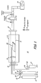
- FIG. 1 presents a representation of the reactor, 10 generally.
- Reactor 10 includes a fused silica (quartz) tube 8 1 ⁇ 4" inches (210 mm) in diameter 11 with a graphite insert 12 that was 7 1 ⁇ 4" inches (185 mm) in diameter.
- the graphite insert was used to protect the quartz tube from reacting with the SiC.
- Water cooled stainless steel end caps 13 with fluoroelastomer (Viton®) O-rings and Swagelok TM compression fitting were used to seal off the reactor and deliver the gasses.
- MKS TM Mass Flo Controllers (MFC's) 15 and a Grafoil TM diffuser 17 were used to control the path and flow of gaseous precursors.
- a MKS TM throttling valve 19 and several MKS TM baratron absolute pressure transducers 21 were used to monitor and control the pressure inside the reactor.
- a liquid nitrogen and particulate trap were used to collect the by-products.
- a Leybold Trivac TM D60 vacuum pump 23 provided the vacuum.
- the composites were infiltrated with SiC by first placing the PIP composites 25 twenty inches (0.51 m) inside of the reactor on a graphite holder.
- Gas diffuser 17 was placed approximately two inches (51 mm) in front of the composite 25 and the injector rod for the MTS vapor 27 was located around two inches (51 mm) in front of the diffuser.
- the reactor was initially pumped down to a base pressure of less than 1 mTorr (0.133 Pa) then back filled three times with ultra high purity nitrogen 29 to remove any oxygen from the system.
- the chamber was isolated from the pumped and the reactor was checked for leaks until a leak rate of 300 mTorr/hour (40 Pa/hour) or less was obtained.
- the reactor was then brought up to deposition temperature of 1050°C in flowing nitrogen (50 sccm (84.5x10 3 Pam 3 /s) at a rate of 50°C/min. After equilibration, the nitrogen flow rate was increased to 400 sccm (676x10 -3 Pam 3 /s) and ultra high purity hydrogen 31 was introduced into the reactor at a flow rate of 400 sccm (676x10 -3 Pam 3/ s). After several minutes, the pressure was stabilized to 6 torr (0.8 Pa) and Methyltrichlorosilane (MTS) 27 was allowed to flow into the reactor at a rate of 50 to 70 sccm (84.5x10 -3 to 118x10 -3 Pam 3 /s).
- MTS Methyltrichlorosilane
- Table 1 presents the results of the infiltration times versus the partial densification for the four composites fabricated.
- the green body possesses the greatest amount of porosity and took the longest time to infiltrate with CVI SiC.
- Composites labeled, "One Impregnation and Three Impregnation” were infiltrated in the same run. The difference in the post CVI densities for the two composites is most likely related to the higher density of CVI SiC over that of the polymer ceramic char.
- the composite labeled five impregnation" had the highest initial density and took only around 50 hours to infiltrate.
- Table 2 presents the bulk density and % open porosity before and after the densification processes on the four different composites. In all measured samples, the open porosity was decreased significantly after the CVI process. Table 2 Bulk density and % open porosity before and after infiltration Composite Bulk Density (g/cm 3 ) Bulk Density (g/cm 3 ) % Increase in Density % Open Porosity % Open Porosity Pre-CVI Post CVI Pre-CVI Post CVI Green Body 1.7 2.134 26% 10.662% One Impregnation 1.810 2.137 15% 27.061% 13.700% Three Impregnations 1.952 2.121 8.0% 18.415% 10.514% Five Impregnations 1.944 2.123 8.4% 11.809% 7.836%
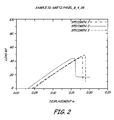
- Figure 2 presents the results of the 4-point bend test on three samples cut from the composite designated "green body" after one, three and five impregnations respectively.
- the strengths of the composites presented in Figure 2 were compared with composites that were infiltrated using only the PIP process using the same fiber lot and the same fiber coating run.
- the results of the 4-point bend testing showed that the strengths of the PIP/CVI composites were at the upper end of the strength range.
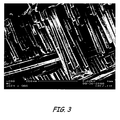
- Figure 3 presents a SEM fractograph of the one of the PIP/CVI composites (labelled green body) after bend testing.
- This composite shows a consider amount of fiber pullout which supports the displacement section of the cure shown in Figure 2 .
- the extent of fiber pullout indicates a tough composite.
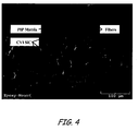
- Figure 4 presents a SEM micrograph of a polished section of the first composite (labelled green body) after the CVI process.
- the lighter area of the matrix shown in the micrograph has been attributed to CVI deposited SiC.
- the SiC can be seen enveloping the outside of the composite indicating the composite was "canned off" during the CVI process. This canning off process prevents additional SiC from infiltrating into the composite and filling up the remaining porosity. This is a common occurrence in the CVI process and can be minimized by reducing the deposition rate. Even though the composite was canned off during the CVI process, a considerable amount of opened porosity was filled in with SiC.
- Figure 5 presents a SEM micrograph of a PIP/CVI composite.
- the lighter areas around the fiber show the CVI SiC infiltrating through an open pore and around the fibers as is desired.
Landscapes
- Chemical & Material Sciences (AREA)
- Engineering & Computer Science (AREA)
- Ceramic Engineering (AREA)
- Manufacturing & Machinery (AREA)
- Materials Engineering (AREA)
- Organic Chemistry (AREA)
- Structural Engineering (AREA)
- Inorganic Chemistry (AREA)
- Chemical Kinetics & Catalysis (AREA)
- Mechanical Engineering (AREA)
- Metallurgy (AREA)
- General Chemical & Material Sciences (AREA)
- Ceramic Products (AREA)
Abstract
Description
- The present invention relates to a family of materials commonly referred to as non-oxide ceramic matrix composites (hereinafter CMC).
- CMC materials are used in many applications where there is a hot structure in the presence of an air breathing or oxidizing environment, such as gas turbine blades, turbine exhaust systems, vanes, shrouds, liners, hypersonic vehicles where the leading edge is in an oxidizing environment, and the like.
- These materials are typically comprised of a matrix phase composed of a non-oxide ceramic such as silicon carbide (SiC), silicon nitride (Si3N4) or mixed ceramic phases such as silicon carbo-nitride (SiNC). The matrix phases are reinforced with continuous ceramic fibers, typically SiC type such as Nicalon™ CG grade, Hi Nicalon™, Nicalon™ type-s, Ube™, or Sylramic™, etc. These materials may or may not be stoichiometric or completely crystalline. The presence of less or more than a full stoichiometric amount simply means that there is an excess of one or the other of silicon or carbon, creating, for example, zones of amorphous materials.
- Recent developments in manufacturing have looked into the ability to coat large quantities of woven ceramic cloth with an interfacial coating that provides the proper de-bonding properties needed to fabricate high temperature composites. This interfacial coating material, such as carbon or boron nitride, acts as a de-bonding agent, providing a weak bond between the fiber and the matrix, which in turn provides a toughening mechanism for the CMC.
- To date the most effective method for depositing the fiber interface on the ceramic cloth is by the chemical vapor infiltration (CVI) process. The CVI process is a non-line-of-sight coating process that has the ability to produce highly dense coatings ranging from several angstroms to several inches in thickness.
- In the past, either CVI or Polymer Infiltration Pyrolysis (PIP) processes have been used to fabricate CMC materials. When either process is used, the interface coating has been applied via a CVI process to a dry fiber preform.
- In the traditional CVI process, ceramic cloth is layed-up and compressed in graphite tooling to create a dry fiber preforms, followed by the deposition of the interface coating. It requires a considerable amount of force to compress the plies together to achieve the desired fiber volume (from around 30 to 40%). Due to the stiffness of coated cloth as opposed to non-coated cloth, the force needed to compress the coated plies together is extremely high and difficult to obtain. This is why the interface coating is almost exclusively applied in the graphite tooling. When considering large composites, this limits the process to uncoated cloth. In addition, complex shapes are difficult to fabricate due to the complex tooling needed to form the shape. This method does not allow full utilization of PMC (Polymer Matrix Composite) composite preform fabrication techniques and adds to production costs.
- After the interface coating has been deposited, the coated preform is either removed from the tooling at this point or left in the tooling, depending on the thickness of the interface coating. If the preform is not removed from the tooling, then matrix material is usually infiltrated until there is sufficient ply-to-ply bonding to hold the preform together. Once a free standing preform is obtained, additonal matrix material is infiltrated into the fiber preform. The benefits of this process are (1) high density of around 95% of theoretical, (2) closed porosity, (3) the matrix is grown around the fiber interface, and (4) the matrix may be an amorphous or crystalline material.
- In the PIP process, a fiber perform / green body is fabricated from previously interface coated fabric through the layup and forming of the desired shape and impregnation with and subsequent curing of a pre-ceramic polymer. The fabrication of this green body utilizes mature manufacturing techniques that are employed in the mass production of polymer matrix composites such as Resin Transfer Molding (RTM), pre-preg layup and vacuum bagging or compression molding. The green body is then pyrolysed in a controlled atmosphere to convert the polymer to a ceramic char. In this process only around 70 % to 80 % of the polymer is converted to a ceramic material accompanied by the related shrinkage due to out-gassing and material density increase due to conversion from polymer to ceramic. Therefore, multiple impregnation and pyrolysis cycles (up to 9 to 12) are needed to obtain a high density. In addition, the evolution of gaseous species during the polymer-to-ceramic convention process produces an appreciable amount of open porosity. This open porosity provides a pathway into the composite for oxidation. One of the highlights of the PIP process is the ability to use conventional methods like injection molding and RTM processes to manufacture the green body. This technology is well known from the plastic industry and can be easily adapted to inorganic polymers. This process provides the ability to form reproducible complex shapes and sizes.
- The PIP process for CMC fabrication has the advantage of using proven PMC type processes, such as RTM, prepreg layup, etc. These processes have been successfully automated to produce high quality/quantity composites at low costs. The drawbacks to current PIP processing of CMC's is the resulting micro-cracked/micro-porous matrix that reduces thermal conductivity and provides a path for oxygen ingress and the resulting environmental degradation of the composite. The CVI approach to CMC fabrication has the advantage of producing a highly dense, crystalline matrix. This results in improved preformance and lends itself to advanced manufacturing concepts that incorporate self-sealing systems into the manufacturing process. The CVI approach suffers from labour intensive assembly of the preform into the required tooling to hold the preform together until there is enough CVI matrix to make the structure free standing. This initial stage of traditional CVI processing does not lend itself to easy automation for volume production and the required graphite tooling makes the fabrication of highly complex shapes very difficult and expensive.
- The present invention provides a method to use PIP and CVI composite manufacturing processes combined in such a way to enable a low cost/high volume approach to advanced CMC materials.
- Viewed from a first aspect, the present invention provides a method of forming a highly densified ceramic matrix composite (CMC), comprising: forming a preform of a matrix formed from a non-oxide ceramic and continuous ceramic fibers and adding an interface coating; partially densifying the preform with a resin to increase the density of the preform using a polymer infiltration pyrolysis (PIP) process; and infiltrating the preform using a chemical vapor infiltration process (CVI) to a final density.
- The method includes the combination of both PIP and CVI to incorporate the efficiency of automation and large volume production of PIP processing to form a complex shape, free standing CMC body, then complete the matrix infiltration with a CVI process to achieve the enhanced properties of a CVI CMC with a low cost/high volume process. The number of PIP cycles used, and the subsequent amount of CVI infiltration that is performed is dependant on the application and the desired properties. The technique can be used to form an essentially 100% CVI based composite, or conversely used to add some environmental protection to a PIP based CMC through infiltration of the micro-porosity in the matrix.
- The invention comprises a method of forming a highly densified CMC composite by forming a preform of a matrix formed from a non-oxide ceramic and continuous ceramic fibers and adding an interface coating. The preform is partially densified with a resin to increase the density thereof using a PIP process. Then, the preform is infiltrated using a CVI process to a final density.
- Viewed from another aspect, the present invention provides a method of forming a highly densified ceramic matrix composite (CMC) composite, comprising: forming a preform from a plurality of layers of a ceramic fiber impregnated with a resin the plurality of layers being layed-up on a predetermined orientation to form a green composite having desired shape; partially densifying the preform with a resin to increase the density of the preform using a polymer infiltration pyrolysis (PIP) process decompose to form ceramic char; and infiltrating the preform using a process chemical vapor infiltration (CVI) process to a finally density of at least 95% of theoretical.
- Viewed from a further aspect, the present invention provides a highly densified ceramic matrix composite (CMC) having a final density that has been formed by: forming a preform of a matrix formed from a non-oxide ceramic and continuous ceramic fibers and adding an interface coating; partially densifying the preform with a resin to increase the density of the preform using a polymer infiltration pyrolysis (PIP) process; and infiltrating the preform using a chemical vapor infiltration (CVI) process to a final density.
- Certain preferred embodiments of the present invention will now be described in greater detail by way of example only and with reference to the accompanying drawings, in which:
-
FIGURE 1 is a block diagram of a CVI reactor used on PIP composites; -
FIGURE 2 is a graph showing the results of tests on experimental samples; -
FIGURE 3 is a SEM fractograph of an experimental sample; -
FIGURE 4 is a SEM micrograph of a CMC composite of this invention; and -
FIGURE 5 is another SEM micrograph of another CMC composite of this invention. - The method of this invention includes the use of both a PIP process and a CVI process.
- In the PIP process, a fiber perform / green body is fabricated from CVI interface coated fibers or fabric by impregnation with and subsequent curing of an inorganic polymer. The fabrication of this green body utilizes established manufacturing techniques that are employed in the mass production of polymer matrix composites such as the previously mentioned RTM, pre-preg layup, and vacuum bagging. The green body is then pyrolysed in a controlled atmosphere to convert the polymer to a ceramic char. In this process only around 70 % to 80 % of the polymer is converted to a ceramic material. Therefore, multiple impregnation and pyrolysis cycles (such as up to 9 to 12 cycles) are needed to obtain a desired high density of 90% to essentially 100%. In addition, the evolution of gas species during the polymer to ceramic convention process produces an appreciable amount of open porosity. This open porosity provides a pathway into the composite for unwanted oxidation. Still, one of the highlights of the PIP process is the ability to use conventional methods like injection molding and RTM process to manufacture the green body. This technology is well known from the plastic industry and is easily adapted to inorganic polymers. This process provides the ability to form reproducible complex shapes and sizes.
- In the CVI process, ceramic cloth is layed-up and compressed in graphite tooling to create a dry fiber preform, followed by the deposition of the interface coating. When considering large or complex composites, complex and costly graphite tooling is typically required to ensure proper fiber volume fraction and preform shape, while allowing uniform CVI infiltration for the interface coating and CVI matrix. This tooling is designed to be reusable, but due to the nature of the CVD process, its lifetime is limited to a finite number of components that is significantly shorter than tooling used in PIP processing. This method does not allow full utilization of PMC composite preform fabrication techniques and adds to production costs.
- The present invention employs the advantages of both the PIP process and the CVI process to produce an improved product in a much more economical method.
- In order to evaluate the present invention, experimental composites were prepared and compared. In a first process, eight plies of Nicalon™ fabric (previously coated with a duplex BN/Si3N4 fiber coating) were impregnated with a polysilazane resin (COIC S-200) containing less than fifteen percent 30µm α-silicon nitride filler. The plies of fabric were layed-up in a warp aligned symmetric orientation and were impregnated using standard vacuum bag processing techniques. After impregnation, the green composites were put through a standard pyrolysis cycle to decompose the polymer into a ceramic char. Typically, this process reached temperatures greater than one thousand degrees Celsius.
- One composite labeled "green body" was subjected only to the first impregnation and pyrolysis cycle. Another composite denoted "three impregnations" went through this impregnation and pyrolysis cycle three times. The number of times that the composite went through the cycle corresponds directly to the name of the composite.
- Silicon carbide was infiltrated into the partially densified composites by use of a hot wall low pressure CVD reactor.
Figure 1 presents a representation of the reactor, 10 generally.Reactor 10 includes a fused silica (quartz) tube 8 ¼" inches (210 mm) indiameter 11 with agraphite insert 12 that was 7 ¼" inches (185 mm) in diameter. The graphite insert was used to protect the quartz tube from reacting with the SiC. Water cooled stainless steel end caps 13 with fluoroelastomer (Viton®) O-rings and Swagelok™ compression fitting were used to seal off the reactor and deliver the gasses. MKS™ Mass Flo Controllers (MFC's) 15 and a Grafoil™ diffuser 17 were used to control the path and flow of gaseous precursors. A MKS™ throttling valve 19 and several MKS™ baratronabsolute pressure transducers 21 were used to monitor and control the pressure inside the reactor. A liquid nitrogen and particulate trap were used to collect the by-products. A Leybold Trivac™D60 vacuum pump 23 provided the vacuum. - The composites were infiltrated with SiC by first placing the
PIP composites 25 twenty inches (0.51 m) inside of the reactor on a graphite holder.Gas diffuser 17 was placed approximately two inches (51 mm) in front of the composite 25 and the injector rod for theMTS vapor 27 was located around two inches (51 mm) in front of the diffuser. The reactor was initially pumped down to a base pressure of less than 1 mTorr (0.133 Pa) then back filled three times with ultra high purity nitrogen 29 to remove any oxygen from the system. The chamber was isolated from the pumped and the reactor was checked for leaks until a leak rate of 300 mTorr/hour (40 Pa/hour) or less was obtained. The reactor was then brought up to deposition temperature of 1050°C in flowing nitrogen (50 sccm (84.5x10³Pam3/s) at a rate of 50°C/min. After equilibration, the nitrogen flow rate was increased to 400 sccm (676x10-3 Pam3/s) and ultrahigh purity hydrogen 31 was introduced into the reactor at a flow rate of 400 sccm (676x10-3 Pam3/s). After several minutes, the pressure was stabilized to 6 torr (0.8 Pa) and Methyltrichlorosilane (MTS) 27 was allowed to flow into the reactor at a rate of 50 to 70 sccm (84.5x10⁻³ to 118x10-3 Pam3/s). A liquid nitrogen trap was used to trap low molecular weight polysilanes along with other volatile compounds. Table 1 presents the experimental matrix that was used to fabricate the four composites used in this study.Table 1 Experimental parameter used to infiltrate the composites Run Tem. °C MTS sccm* H2 sccm* N2 sccm* Pressure (torr)+ Infiltration Time (hours) Infiltration Rate (g/hr) Green Body 1050 50 400 400 6.00 150 ---- One Impregnation 1050 65-70 400 400 6.00 115 0.17 Three Impregnations 1050 65-70 400 400 6.00 115 0.11 Five Impregnations 1050 65-70 400 400 6.00 50 0.13 * 1 sccm = 1.69x 10⁻³Pam3/s
+ 1 torr = 0.133Pa - Table 1 presents the results of the infiltration times versus the partial densification for the four composites fabricated. The green body possesses the greatest amount of porosity and took the longest time to infiltrate with CVI SiC. Composites labeled, "One Impregnation and Three Impregnation" were infiltrated in the same run. The difference in the post CVI densities for the two composites is most likely related to the higher density of CVI SiC over that of the polymer ceramic char. The composite labeled," five impregnation" had the highest initial density and took only around 50 hours to infiltrate.
- Table 2 presents the bulk density and % open porosity before and after the densification processes on the four different composites. In all measured samples, the open porosity was decreased significantly after the CVI process.
Table 2 Bulk density and % open porosity before and after infiltration Composite Bulk Density (g/cm3) Bulk Density (g/cm3) % Increase in Density % Open Porosity % Open Porosity Pre-CVI Post CVI Pre-CVI Post CVI Green Body 1.7 2.134 26% 10.662% One Impregnation 1.810 2.137 15% 27.061% 13.700% Three Impregnations 1.952 2.121 8.0% 18.415% 10.514% Five Impregnations 1.944 2.123 8.4% 11.809% 7.836% -
Figure 2 presents the results of the 4-point bend test on three samples cut from the composite designated "green body" after one, three and five impregnations respectively. The strengths of the composites presented inFigure 2 were compared with composites that were infiltrated using only the PIP process using the same fiber lot and the same fiber coating run. The results of the 4-point bend testing showed that the strengths of the PIP/CVI composites were at the upper end of the strength range. -
Figure 3 presents a SEM fractograph of the one of the PIP/CVI composites (labelled green body) after bend testing. This composite shows a consider amount of fiber pullout which supports the displacement section of the cure shown inFigure 2 . The extent of fiber pullout indicates a tough composite. Both of these results showed that the process of infiltrating the partially infiltrated PIP composites with CVI SiC did not affect the strength or toughness of the composites. -
Figure 4 presents a SEM micrograph of a polished section of the first composite (labelled green body) after the CVI process. The lighter area of the matrix shown in the micrograph has been attributed to CVI deposited SiC. The SiC can be seen enveloping the outside of the composite indicating the composite was "canned off" during the CVI process. This canning off process prevents additional SiC from infiltrating into the composite and filling up the remaining porosity. This is a common occurrence in the CVI process and can be minimized by reducing the deposition rate. Even though the composite was canned off during the CVI process, a considerable amount of opened porosity was filled in with SiC. -
Figure 5 presents a SEM micrograph of a PIP/CVI composite. The lighter areas around the fiber show the CVI SiC infiltrating through an open pore and around the fibers as is desired. - In summary, the ability to fabricate ceramic matrix composites using the PIP/ CVI process was demonstrated. Several different PIP composites were fabricated to various densities. These composites were then infiltrated in a CVI process with SiC to a final density of around 2.1 g/cm3. Four-point bend testing showed that the strength of the composite was not affected by the CVI process. SEM fractographs of the composites after testing showed a considerable amount of fiber pullout. SEM micrograph of the polished surface of the composites showed that the CVI process was able to penetrate into the partially impregnated composites and fill in some of the micro-porosity.
- While the invention has been described with reference to an exemplary embodiment(s), it will be understood by those skilled in the art that various changes may be made and equivalents may be substituted for elements thereof without departing from the scope of the invention. In addition, many modifications may be made to adapt a particular situation or material to the teachings of the invention without departing from the essential scope thereof. Therefore, it is intended that the invention not be limited to the particular embodiment(s) disclosed, but that the invention will include all embodiments falling within the scope of the appended claims.
Claims (15)
- A method of forming a highly densified ceramic matrix composite (CMC), comprising:forming a preform of a matrix formed from a non-oxide ceramic and continuous ceramic fibers and adding an interface coating;partially densifying the preform with a resin to increase the density of the preform using a polymer infiltration pyrolysis (PIP) process; andinfiltrating the preform using a chemical vapor infiltration process (CVI) to a final density.
- The method of claim 1, wherein the preform is formed from a plurality of layers of a ceramic fiber impregnated with a resin, the plurality of layers being layed-up on a predetermined orientation to form a green composite having desired shape.
- The method of claim 2, wherein the impregnated resin is decomposed to ceramic char.
- The method of claim 3, wherein the green composite is impregnated and decomposed a plurality of times to form a densified preform.
- The method of any preceding claim, wherein the preform is infiltrated by the CVI process to increase the density and reduce porosity of the CMC composite.
- The method of any preceding claim, wherein the non-oxide ceramic is selected from the group consisting of silicon carbide, silicon nitride, silicon carbo-nitride and mixtures thereof.
- The method of any preceding claim, wherein the ceramic fiber is formed from continuous silicon carbide fiber.
- The method of any preceding claim, wherein the composite has a final density of at least 90% of theoretical.
- The method of claim 8, wherein the composite has a final density of at least 95% of theoretical.
- A highly densified ceramic matrix composite (CMC) having a final density that has been formed by:forming a preform of a matrix formed from a non-oxide ceramic and continuous ceramic fibers and adding an interface coating;partially densifying the preform with a resin to increase the density of the preform using a polymer infiltration pyrolysis (PIP) process; and infiltrating the preform using a chemical vapor infiltration (CVI) process to a final density.
- The composite of claim 10, wherein the preform has been formed from a plurality of layers of a ceramic fiber impregnated with a resin the plurality of layers being layed-up on a predetermined orientation to form a green composite having desired shape.
- The composite of claim 10 or 11, wherein the densifying resin has been decomposed to form ceramic char during the production of the ceramic matrix composite.
- The composite of claim 10, 11 or 12, wherein the green composite has been impregnated and decomposed a plurality of times to form a densified preform during the production of the ceramic matrix composite.
- The composite of any of claims 10 to 13, wherein the preform has been infiltrated by the CVI process to increase the density and reduce porosity of the CMC composite during the production of the ceramic matrix composite.
- The composite of claim 14, wherein the non-oxide ceramic has been selected from the group consisting of silicon carbide, silicon nitride, silicon carbo-nitride and mixtures thereof, and more preferably the ceramic fiber has been formed from continuous silicon carbide fiber.
Applications Claiming Priority (1)
| Application Number | Priority Date | Filing Date | Title |
|---|---|---|---|
| US12/566,339 US20110071014A1 (en) | 2009-09-24 | 2009-09-24 | Hybred polymer cvi composites |
Publications (1)
| Publication Number | Publication Date |
|---|---|
| EP2308811A1 true EP2308811A1 (en) | 2011-04-13 |
Family
ID=43259792
Family Applications (1)
| Application Number | Title | Priority Date | Filing Date |
|---|---|---|---|
| EP10251648A Withdrawn EP2308811A1 (en) | 2009-09-24 | 2010-09-24 | Hybred polymer CVI composites |
Country Status (2)
| Country | Link |
|---|---|
| US (2) | US20110071014A1 (en) |
| EP (1) | EP2308811A1 (en) |
Cited By (1)
| Publication number | Priority date | Publication date | Assignee | Title |
|---|---|---|---|---|
| EP2574604A3 (en) * | 2011-09-30 | 2013-05-22 | United Technologies Corporation | Method for Fabricating Ceramic Material |
Families Citing this family (19)
| Publication number | Priority date | Publication date | Assignee | Title |
|---|---|---|---|---|
| US8545938B2 (en) * | 2011-10-03 | 2013-10-01 | United Technologies Corporation | Method of fabricating a ceramic component |
| US9701591B2 (en) | 2011-10-12 | 2017-07-11 | United Technologies Corporation | Method for fabricating a ceramic material |
| US9533919B2 (en) | 2011-10-12 | 2017-01-03 | United Technologies Corporation | Method for fabricating a ceramic material |
| US20150275686A1 (en) * | 2013-02-23 | 2015-10-01 | Rolls-Royce Corporation | Edge seal for gas turbine engine ceramic matrix composite component |
| US10294166B2 (en) | 2013-09-19 | 2019-05-21 | United Technologies Corporation | Densified polymer infiltrated and pyrolysis-based CMC articles |
| WO2015108579A2 (en) | 2013-10-14 | 2015-07-23 | United Technologies Corporation | Assembly and method for transfer molding |
| EP3057747B1 (en) | 2013-10-14 | 2020-01-22 | United Technologies Corporation | Assembly and method for transfer molding |
| CN104446590B (en) * | 2014-12-24 | 2016-01-13 | 中南大学 | A kind of preparation method of continuous fiber reinforced carbon/carbon-molybdenum composite material |
| KR102318231B1 (en) * | 2015-01-29 | 2021-10-27 | 엘지이노텍 주식회사 | Inorganic filler, resin composition comprising the same and heat radiation board using the same |
| US10465534B2 (en) | 2015-06-05 | 2019-11-05 | Rolls-Royce North American Technologies, Inc. | Machinable CMC insert |
| US10458653B2 (en) * | 2015-06-05 | 2019-10-29 | Rolls-Royce Corporation | Machinable CMC insert |
| US10472976B2 (en) * | 2015-06-05 | 2019-11-12 | Rolls-Royce Corporation | Machinable CMC insert |
| US9850174B2 (en) | 2016-03-23 | 2017-12-26 | General Electric Company | Ceramic matrix composites having monomodal pore size distribution and low fiber volume fraction |
| US10801108B2 (en) * | 2017-08-28 | 2020-10-13 | Raytheon Technologies Corporation | Method for fabricating ceramic matrix composite components |
| CN110263394B (en) * | 2019-06-05 | 2022-06-07 | 上海大学 | A Boltzmann-based Simulation Method for CVI Densification Process of Composite Materials |
| CN113979784B (en) * | 2020-11-23 | 2023-04-18 | 航天特种材料及工艺技术研究所 | High-density ceramic matrix composite and preparation method thereof |
| CN114133259A (en) * | 2021-09-26 | 2022-03-04 | 中国科学院金属研究所 | A kind of preparation method of resin-modified C/(C-)SiC-ZrC composite material |
| US20240116828A1 (en) * | 2022-10-07 | 2024-04-11 | Raytheon Technologies Corporation | Ceramic matrix composite article and method of making the same |
| CN120533803A (en) * | 2025-05-27 | 2025-08-26 | 武汉理工大学 | Continuous robotic additive manufacturing device and method for ceramic composites based on fiber interface layer preparation |
Citations (6)
| Publication number | Priority date | Publication date | Assignee | Title |
|---|---|---|---|---|
| EP1024121A2 (en) * | 1999-01-28 | 2000-08-02 | Ishikawajima-Harima Heavy Industries Co., Ltd. | Ceramic-based composite member and its manufacturing method |
| EP1277716A1 (en) * | 2001-07-04 | 2003-01-22 | Ishikawajima-Harima Heavy Industries Co., Ltd. | Method for fabricating ceramic matrix composite |
| US20050181192A1 (en) * | 2001-01-16 | 2005-08-18 | Steffier Wayne S. | Fiber-reinforced ceramic composite material comprising a matrix with a nanolayered microstructure |
| WO2006076069A1 (en) * | 2005-01-12 | 2006-07-20 | The Boeing Company | Method for manufacturing ceramic matrix composite structures |
| FR2882356A1 (en) * | 2005-02-23 | 2006-08-25 | Snecma Propulsion Solide Sa | Fabrication of a composite material component with a ceramic matrix and reinforcing fibres using an interphase coating, notably for aeronautical and spatial structural components subjected to hot gases |
| EP1702908A1 (en) * | 2004-01-08 | 2006-09-20 | Ishikawajima-Harima Heavy Industries Co., Ltd. | Composite material and method for producing same |
Family Cites Families (11)
| Publication number | Priority date | Publication date | Assignee | Title |
|---|---|---|---|---|
| US5290491A (en) * | 1990-04-02 | 1994-03-01 | Societe Europeenne De Propulsion | Process for the manufacture of a thermostructural composite material having a carbon interphase between its reinforcement fibers and its matrix |
| EP0798280B1 (en) * | 1996-03-29 | 2001-09-12 | Kabushiki Kaisha Toshiba | Ceramic matrix composite and method of manufacturing the same |
| US6743393B1 (en) * | 1998-06-17 | 2004-06-01 | Coi Ceramics, Inc. | Method for producing ceramic matrix composites |
| US6350713B1 (en) * | 1998-11-24 | 2002-02-26 | Dow Corning Corporation | Ceramic matrix composites |
| CA2299225C (en) * | 1999-09-06 | 2006-09-19 | Ishikawajima-Harima Heavy Industries Co., Ltd. | Method and apparatus for manufacturing ceramic-based composite member |
| US6506483B1 (en) * | 2000-04-28 | 2003-01-14 | Technology Assessment & Transfer, Inc. | Ceramic fiber debond coatings |
| US7378362B2 (en) * | 2000-09-29 | 2008-05-27 | Goodrich Corporation | Boron carbide based ceramic matrix composites |
| JP3971903B2 (en) * | 2001-05-31 | 2007-09-05 | 独立行政法人科学技術振興機構 | Method for producing SiC fiber reinforced SiC composite material |
| DE10204860A1 (en) * | 2002-02-06 | 2003-08-14 | Man Technologie Gmbh | Fiber composite ceramic material, used e.g. for heat engine, heat exchanger, hot gas pipe or nozzle or plasma containing vessel, has heat-conducting three-dimensional fabric with silicon carbide matrix produced in three stages |
| US7306826B2 (en) * | 2004-02-23 | 2007-12-11 | General Electric Company | Use of biased fabric to improve properties of SiC/SiC ceramic composites for turbine engine components |
| US7597838B2 (en) * | 2004-12-30 | 2009-10-06 | General Electric Company | Functionally gradient SiC/SiC ceramic matrix composites with tailored properties for turbine engine applications |
-
2009
- 2009-09-24 US US12/566,339 patent/US20110071014A1/en not_active Abandoned
-
2010
- 2010-09-24 EP EP10251648A patent/EP2308811A1/en not_active Withdrawn
-
2013
- 2013-03-26 US US13/850,367 patent/US20130323417A1/en not_active Abandoned
Patent Citations (6)
| Publication number | Priority date | Publication date | Assignee | Title |
|---|---|---|---|---|
| EP1024121A2 (en) * | 1999-01-28 | 2000-08-02 | Ishikawajima-Harima Heavy Industries Co., Ltd. | Ceramic-based composite member and its manufacturing method |
| US20050181192A1 (en) * | 2001-01-16 | 2005-08-18 | Steffier Wayne S. | Fiber-reinforced ceramic composite material comprising a matrix with a nanolayered microstructure |
| EP1277716A1 (en) * | 2001-07-04 | 2003-01-22 | Ishikawajima-Harima Heavy Industries Co., Ltd. | Method for fabricating ceramic matrix composite |
| EP1702908A1 (en) * | 2004-01-08 | 2006-09-20 | Ishikawajima-Harima Heavy Industries Co., Ltd. | Composite material and method for producing same |
| WO2006076069A1 (en) * | 2005-01-12 | 2006-07-20 | The Boeing Company | Method for manufacturing ceramic matrix composite structures |
| FR2882356A1 (en) * | 2005-02-23 | 2006-08-25 | Snecma Propulsion Solide Sa | Fabrication of a composite material component with a ceramic matrix and reinforcing fibres using an interphase coating, notably for aeronautical and spatial structural components subjected to hot gases |
Non-Patent Citations (1)
| Title |
|---|
| ORTONA A ET AL: "SiC-SiCf CMC manufacturing by hybrid CVI-PIP techniques: process optimisation", FUSION ENGINEERING AND DESIGN, ELSEVIER SCIENCE PUBLISHERS, AMSTERDAM, NL, vol. 51-52, 1 November 2000 (2000-11-01), pages 159 - 163, XP004315159, ISSN: 0920-3796, DOI: 10.1016/S0920-3796(00)00310-0 * |
Cited By (2)
| Publication number | Priority date | Publication date | Assignee | Title |
|---|---|---|---|---|
| EP2574604A3 (en) * | 2011-09-30 | 2013-05-22 | United Technologies Corporation | Method for Fabricating Ceramic Material |
| US9533918B2 (en) | 2011-09-30 | 2017-01-03 | United Technologies Corporation | Method for fabricating ceramic material |
Also Published As
| Publication number | Publication date |
|---|---|
| US20130323417A1 (en) | 2013-12-05 |
| US20110071014A1 (en) | 2011-03-24 |
Similar Documents
| Publication | Publication Date | Title |
|---|---|---|
| EP2308811A1 (en) | Hybred polymer CVI composites | |
| US12030820B2 (en) | High temperature fiber, method of making and high temperature fiber composites | |
| CN107226706B (en) | Ceramic matrix composites having unimodal pore size distribution and low fiber volume fraction | |
| CN101863665B (en) | Method for preparing self-healing anti-oxidation functional fiber reinforced ceramic matrix composite material | |
| Xu et al. | Three‐dimensional carbon/silicon carbide composites prepared by chemical vapor infiltration | |
| CA2444963C (en) | A method of manufacturing a sic fiber-reinforced sic-matrix composite | |
| EP2308810A1 (en) | Ceramic matrix composite system and method of manufacture | |
| US6203904B1 (en) | Silicon carbide fibers with boron nitride coatings | |
| EP2543650A1 (en) | Method for manufacturing high-density fiber reinforced ceramic composite materials | |
| EP3046892B1 (en) | Method for densifying a cmc article | |
| CN108101566B (en) | Method for preparing silicon carbide ceramic matrix composite component with assistance of RTM (resin transfer molding) process | |
| JPWO2016093360A1 (en) | Silicon carbide fiber reinforced silicon carbide composite material | |
| Nakano et al. | Fabrication and characterization of three‐dimensional carbon fiber reinforced silicon carbide and silicon nitride composites | |
| CN112341235A (en) | Multiphase coupled fast densification method for ultra-high temperature self-healing ceramic matrix composites | |
| CN105272262A (en) | Method for enhancing density of SiC/SiC ceramic matrix composite | |
| JP3034084B2 (en) | Oxidation resistant carbon fiber reinforced carbon composite material and method for producing the same | |
| CN112521156B (en) | Hybrid matrix SiCf/SiC composite material and preparation method thereof | |
| WO2006076069A1 (en) | Method for manufacturing ceramic matrix composite structures | |
| EP3957620B1 (en) | Method of making a ceramic matrix composite that exhibits moisture and environmental resistance | |
| Wang et al. | Fabrication of carbon fiber reinforced ceramic matrix composites with improved oxidation resistance using boron as active filler | |
| US10472713B2 (en) | Method for ceramic matrix composite with carbon coating for wetting | |
| KR101623914B1 (en) | Method for fabrication of high density SiCf/SiC composites with homogeneous microstructure | |
| US20250230104A1 (en) | High temperature fiber, method of making and high temperature fiber composites | |
| JP2000219584A (en) | Carbon fiber reinforced carbon composite material coated with silicon carbide and its production | |
| Dong et al. | Preparation of oxidation-protective SiC coatings for C/SiC composites by pulsed chemical vapor deposition |
Legal Events
| Date | Code | Title | Description |
|---|---|---|---|
| PUAI | Public reference made under article 153(3) epc to a published international application that has entered the european phase |
Free format text: ORIGINAL CODE: 0009012 |
|
| AK | Designated contracting states |
Kind code of ref document: A1 Designated state(s): AL AT BE BG CH CY CZ DE DK EE ES FI FR GB GR HR HU IE IS IT LI LT LU LV MC MK MT NL NO PL PT RO SE SI SK SM TR |
|
| AX | Request for extension of the european patent |
Extension state: BA ME RS |
|
| 17P | Request for examination filed |
Effective date: 20111013 |
|
| 17Q | First examination report despatched |
Effective date: 20120329 |
|
| STAA | Information on the status of an ep patent application or granted ep patent |
Free format text: STATUS: THE APPLICATION IS DEEMED TO BE WITHDRAWN |
|
| 18D | Application deemed to be withdrawn |
Effective date: 20150501 |
|
| R18D | Application deemed to be withdrawn (corrected) |
Effective date: 20150512 |