EP2308697B1 - Tire - Google Patents
Tire Download PDFInfo
- Publication number
- EP2308697B1 EP2308697B1 EP09794344A EP09794344A EP2308697B1 EP 2308697 B1 EP2308697 B1 EP 2308697B1 EP 09794344 A EP09794344 A EP 09794344A EP 09794344 A EP09794344 A EP 09794344A EP 2308697 B1 EP2308697 B1 EP 2308697B1
- Authority
- EP
- European Patent Office
- Prior art keywords
- tire
- block land
- sipe
- land portion
- circumferential direction
- Prior art date
- Legal status (The legal status is an assumption and is not a legal conclusion. Google has not performed a legal analysis and makes no representation as to the accuracy of the status listed.)
- Not-in-force
Links
- 230000000052 comparative effect Effects 0.000 description 9
- 238000011161 development Methods 0.000 description 9
- 230000000694 effects Effects 0.000 description 7
- 230000008859 change Effects 0.000 description 6
- 238000012360 testing method Methods 0.000 description 6
- 230000001965 increasing effect Effects 0.000 description 5
- 238000006243 chemical reaction Methods 0.000 description 3
- 230000006866 deterioration Effects 0.000 description 3
- XEEYBQQBJWHFJM-UHFFFAOYSA-N Iron Chemical compound [Fe] XEEYBQQBJWHFJM-UHFFFAOYSA-N 0.000 description 2
- 239000012141 concentrate Substances 0.000 description 2
- 230000003993 interaction Effects 0.000 description 2
- 230000004048 modification Effects 0.000 description 2
- 238000012986 modification Methods 0.000 description 2
- 230000001133 acceleration Effects 0.000 description 1
- 230000009471 action Effects 0.000 description 1
- 238000010276 construction Methods 0.000 description 1
- 230000003247 decreasing effect Effects 0.000 description 1
- 238000006073 displacement reaction Methods 0.000 description 1
- 230000002708 enhancing effect Effects 0.000 description 1
- 238000011156 evaluation Methods 0.000 description 1
- 229910052742 iron Inorganic materials 0.000 description 1
- 230000007246 mechanism Effects 0.000 description 1
- 230000002035 prolonged effect Effects 0.000 description 1
- 238000009877 rendering Methods 0.000 description 1
- 230000002195 synergetic effect Effects 0.000 description 1
- 238000012546 transfer Methods 0.000 description 1
- XLYOFNOQVPJJNP-UHFFFAOYSA-N water Substances O XLYOFNOQVPJJNP-UHFFFAOYSA-N 0.000 description 1
Images


Classifications
-
- B—PERFORMING OPERATIONS; TRANSPORTING
- B60—VEHICLES IN GENERAL
- B60C—VEHICLE TYRES; TYRE INFLATION; TYRE CHANGING; CONNECTING VALVES TO INFLATABLE ELASTIC BODIES IN GENERAL; DEVICES OR ARRANGEMENTS RELATED TO TYRES
- B60C11/00—Tyre tread bands; Tread patterns; Anti-skid inserts
- B60C11/03—Tread patterns
- B60C11/13—Tread patterns characterised by the groove cross-section, e.g. for buttressing or preventing stone-trapping
-
- B—PERFORMING OPERATIONS; TRANSPORTING
- B60—VEHICLES IN GENERAL
- B60C—VEHICLE TYRES; TYRE INFLATION; TYRE CHANGING; CONNECTING VALVES TO INFLATABLE ELASTIC BODIES IN GENERAL; DEVICES OR ARRANGEMENTS RELATED TO TYRES
- B60C11/00—Tyre tread bands; Tread patterns; Anti-skid inserts
- B60C11/03—Tread patterns
- B60C11/0306—Patterns comprising block rows or discontinuous ribs
-
- B—PERFORMING OPERATIONS; TRANSPORTING
- B60—VEHICLES IN GENERAL
- B60C—VEHICLE TYRES; TYRE INFLATION; TYRE CHANGING; CONNECTING VALVES TO INFLATABLE ELASTIC BODIES IN GENERAL; DEVICES OR ARRANGEMENTS RELATED TO TYRES
- B60C11/00—Tyre tread bands; Tread patterns; Anti-skid inserts
- B60C11/03—Tread patterns
- B60C11/12—Tread patterns characterised by the use of narrow slits or incisions, e.g. sipes
- B60C11/1204—Tread patterns characterised by the use of narrow slits or incisions, e.g. sipes with special shape of the sipe
- B60C11/1218—Three-dimensional shape with regard to depth and extending direction
-
- B—PERFORMING OPERATIONS; TRANSPORTING
- B60—VEHICLES IN GENERAL
- B60C—VEHICLE TYRES; TYRE INFLATION; TYRE CHANGING; CONNECTING VALVES TO INFLATABLE ELASTIC BODIES IN GENERAL; DEVICES OR ARRANGEMENTS RELATED TO TYRES
- B60C11/00—Tyre tread bands; Tread patterns; Anti-skid inserts
- B60C11/03—Tread patterns
- B60C11/12—Tread patterns characterised by the use of narrow slits or incisions, e.g. sipes
- B60C11/1236—Tread patterns characterised by the use of narrow slits or incisions, e.g. sipes with special arrangements in the tread pattern
- B60C11/125—Tread patterns characterised by the use of narrow slits or incisions, e.g. sipes with special arrangements in the tread pattern arranged at the groove bottom
-
- B—PERFORMING OPERATIONS; TRANSPORTING
- B60—VEHICLES IN GENERAL
- B60C—VEHICLE TYRES; TYRE INFLATION; TYRE CHANGING; CONNECTING VALVES TO INFLATABLE ELASTIC BODIES IN GENERAL; DEVICES OR ARRANGEMENTS RELATED TO TYRES
- B60C11/00—Tyre tread bands; Tread patterns; Anti-skid inserts
- B60C11/03—Tread patterns
- B60C11/12—Tread patterns characterised by the use of narrow slits or incisions, e.g. sipes
- B60C11/1259—Depth of the sipe
- B60C11/1263—Depth of the sipe different within the same sipe
-
- B—PERFORMING OPERATIONS; TRANSPORTING
- B60—VEHICLES IN GENERAL
- B60C—VEHICLE TYRES; TYRE INFLATION; TYRE CHANGING; CONNECTING VALVES TO INFLATABLE ELASTIC BODIES IN GENERAL; DEVICES OR ARRANGEMENTS RELATED TO TYRES
- B60C11/00—Tyre tread bands; Tread patterns; Anti-skid inserts
- B60C11/03—Tread patterns
- B60C11/12—Tread patterns characterised by the use of narrow slits or incisions, e.g. sipes
- B60C11/1272—Width of the sipe
- B60C11/1281—Width of the sipe different within the same sipe, i.e. enlarged width portion at sipe bottom or along its length
Definitions
- the present invention relates to a tire having, in a tread portion, at least one row of rib-like land portion and sipes provided in the rib-like land portion and, in particular, a tire for heavy load having such a tread construction.
- the present invention aims at enhancing wear resistance, with maintaining traction performance on a wet road surface, of the tire.
- a rib-like land portion exhibits, due to high rigidity thereof, better wear resistance than a block land portion.
- a rib-like land portion has a problem that uneven wear referred to as “river wear", in which vicinities of a tread edge are locally worn in the circumferential direction, tends to occur therein.
- River wear as a kind of uneven wear occurs because small steps appearing in the vicinity of a rib edge due to a lateral force applied to a tire in running of the tire are dragged due to differences in diameter thereof and the dragged steps are subjected to sliding wear, whereby the amount of wear on the edge side of the rib-like land portion exceeds the amount of wear on the center side thereof.
- JP 06-080002 discloses a tire having a rib-like land portion provided with sipes in order to improve traction performance on a wet road surface of a tire having a rib-like land portion.
- Patent document 1 JP 06-080002
- the edge portion on the outer side in the tire widthwise direction of the rib-like land portion exhibits a large magnitude of wear than the edge portion on the inner side in the tire widthwise direction thereof because a larger lateral force is applied to the former.
- an object of the present invention is to provide a tire having a rib-like land portion and sipes provided therein, in which wear resistance has been enhanced by optimizing the shape of the sipes, while good traction performance on a wet road surface is maintained.
- the present invention provides a tire having, in a tread portion, at least one row of rib-like land portion and sipes provided in the rib-like land portion, characterized in that depth of each sipe at least at one end portion thereof on the shoulder side is smaller than depth of the sipe at the remaining portions thereof.
- the minimum depth of the sipe is in the range of 0.50 to 0.95 times as much as the maximum depth thereof.
- the length in the tire widthwise direction of a portion having the maximum depth of the sipe is preferably in the range of 0.1 to 0.9 times as long as the length in the tire widthwise direction of the rib-like land portion.
- the length in the tire widthwise direction of the sipe is preferably at least 0.80 times as long as the length in the tire widthwise direction of the rib-like land portion.
- the depth of the sipe is preferably in the range of at least 0.30 times as much as the depth of each of circumferential grooves provided at respective sides of the rib-like land portion
- the groove bottom of the sipe is provided with an enlarged portion having a length in the tire circumferential direction longer than the opening width of the sipe at a ground contact surface of the tread portion.
- opening width of a sipe represents a length in the tire circumferential direction of a sipe at a ground contact surface of a tread portion.
- the enlarged portion is provided at the groove bottom portion having the maximum depth of the sipe.
- plural rows of block land portions are formed by demarcation by providing plural lateral grooves for communicating adjacent two circumferential grooves with each other; in at least two rows of block land portions adjacent to each other with a circumferential groove therebetween, among the rows of block land portions, the block land portions consisting of the respective rows of block land portions are disposed to be offset with respect to each other in the tire circumferential direction; the extending direction of the groove portion between the block land portions adjacent to each other in the tire widthwise direction is inclined with respect to the tire widthwise direction and tire circumferential direction; and a distance between the block land portions adjacent to each other in the tire widthwise direction is shorter than a distance between the block land portions adjacent to each other in the tire circumferential direction.
- a "groove portion” represents a part of a circumferential groove extending between block land portions adjacent to each other in the tire widthwise direction, and being “disposed to be offset with respect to each other” represents differentiating starting points of disposure pitch in the tire circumferential direction of the block land portions adjacent to each other in the tire widthwise direction, with each other, so that the ends in the circumferential direction of one row of block land portions are not aligned with the ends in the circumferential direction of another row of block land portions adjacent to the one row in the tire widthwise direction.
- a length of each block land portion in a section in the tire widthwise direction thereof preferably increases from the respective ends in the tire circumferential direction of the block land portion toward the center portion thereof
- the center portion of a block land portion represents a region extending, by the length of 5 to 30% of the length in the tire circumferential direction of the block land portion, from the center position to the respective ends in the tire circumferential direction of the block land portion.
- the center portion of a block land portion represents a region obtained by excluding, from an entire block land portion, areas ranging from the respective end portions in the tire circumferential direction to positions inward therefrom by 20% of the length of the block land portion in the tire circumferential direction.
- the ratio of a distance between block land portions adjacent to each other in the tire circumferential direction with respect to a distance between block land portions adjacent to each other in the tire widthwise direction is preferably in the range of 1: 0.85 to 1: 0.3.
- the ratio of the length in the tire circumferential direction of a block land portion with respect to a distance between block land portions adjacent to each other in the tire circumferential direction is preferably in the range of 1: 0.25 to 1: 0.05.
- FIG. 1 (a) is a development view of a part of a tread portion of a representative tire according to the present invention
- FIG. 1(b) is a section cut along the line I-I in FIG. 1(a)
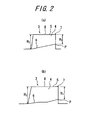
- FIGS. 2(a) and 2(b) are sectional views in the tire widthwise direction of a rib-like land portion of another tire according to the present invention
- FIGS. 3(a) to 3(c) are a section in the tire widthwise direction, a section in the tire circumferential direction and a perspective view, respectively, of a rib-like land portion of yet another tire according to the present invention.
- FIG. 1 (a) is a development view of a part of a tread portion of a representative tire according to the present invention
- FIG. 1(b) is a section cut along the line I-I in FIG. 1(a)
- FIGS. 2(a) and 2(b) are sectional views in the tire widthwise direction of a rib-like land portion of another tire according
- FIG. 4 is a view showing a relationship between presence/absence of driving force exertion and a shifted position of the tread portion.
- FIG. 5 is a view showing shear force applied from a road surface when driving force is exerted on the tread portion.
- FIG. 6 is a view showing deformation in block land portions adjacent to each other when driving force is exerted thereon.
- FIG. 7 is a view showing deformation in block land portions in a case where the block land portions adjacent in the tire circumferential direction are too close to each other.
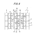
- FIGS. 8 and 9 are development views, respectively, of a part of a tread portion of yet other tires according to the present invention.
- FIG. 10 is a perspective view of a land portion as shown in FIG. 9 .
- FIG. 10 is a perspective view of a land portion as shown in FIG. 9 .
- FIG. 11 (a) is a view showing a block land portion in contact with the ground due to being pushed horizontally with respect to a road surface.
- FIG. 11 (b) is a view showing a block land portion in contact with the ground due to being pushed diagonally with respect to a road surface.
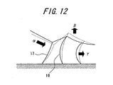
- FIG. 12 is a view showing deformation in block land portions adjacent to each other when driving force is exerted thereon.
- FIG. 13 and FIG. 14 are development views, respectively, of a part of a tread portion of yet other tires according to the present invention.
- FIG. 15 is a perspective view of rib-like land portion of yet another tire according to the present invention
- plural rows of rib-like land portions 3 are formed by demarcation in a tread portion 1 by providing the tread portion with plural circumferential grooves 2 extending in the tire circumferential direction.
- the rib-like land portion 3 is provided with a sipe 4 which communicates in the tire widthwise direction two circumferential grooves 2, 2 adjacent to the rib-like land portion.
- the depth of the sipe 4 measured from a ground contact surface 5 of the tread portion 1 to the groove bottom 6 of the sipe is shorter at an end portion P on the shoulder side than at an end portion on the tire equatorial plane CL side, such that the groove bottom 6 on the shoulder side is positioned relatively shallow.
- the edge portion 7 can satisfactorily resist such lateral force, whereby sliding wear in the edge portion 7 on the outer side in the tire widthwise direction is suppressed.
- difference in wear between the edge portion 7 on the outer side in the tire widthwise direction and the center portion 8 of the rib-like land portion 3 is made relatively small and thus uneven wear can be suppressed.
- the depth of the groove bottom 6 is varied stepwise so that the groove bottom 6 has a stepped configuration having varied depth.
- FIG. 1 the depth of the groove bottom 6 is varied stepwise so that the groove bottom 6 has a stepped configuration having varied depth.
- the depth of the sipe 4 can be varied by monotonously slanting the groove bottom 6 of the sipe 4 with respect to the tire widthwise direction.
- the depth of the sipe 4 can be varied by slanting the groove bottom 6 of the sipe 4 at plural sites at plural different angles.
- the minimum depth H 1 is in the range of 0.50 to 0.95 times as much as the maximum depth H 2 thereof.
- the minimum depth H 1 is smaller than 0.50 times as much as the maximum depth H 2 , although rigidity at the edge portion 7 on the outer side in the tire widthwise direction of the rib-like land portion 3 is sufficiently enhanced and thus uneven wear is suppressed, the traction performance on a wet road surface, which is supposed to be improved by provision of the sipe 4, may deteriorate.
- the minimum depth H 1 exceeds 0.95 times as much as the maximum depth H 2 , although good traction performance on a wet road surface is sufficiently ensured by provision of the sipe 4, uneven wear may not be effectively prevented from occurring because rigidity of the edge portion 7 on the outer side in the tire widthwise direction of the rib-like land portion 3 is not sufficiently enhanced.
- the minimum depth H 1 is in the range of 0.60 to 0.85 times as much as the maximum depth H 2 thereof.
- the length W 1 in the tire widthwise direction of a portion 9 having the maximum depth H 2 of the sipe 4 is preferably in the range of 0.1 to 0.9 times as long as the length W 2 in the tire widthwise direction of the rib-like land portion 3.
- the length W 1 in the tire widthwise direction of a portion 9 having the maximum depth H 2 exceeds 0.9 times as long as the length W 2 in the tire widthwise direction of the rib-like land portion 3, although traction performance on a wet road surface is effectively improved by provision of the sipe 4, uneven wear may not be effectively prevented from occurring because rigidity of the edge portion 7 on the outer side in the tire widthwise direction of the rib-like land portion 3 is not sufficiently enhanced.
- the length W 1 in the tire widthwise direction of the portion 9 having the maximum depth H 1 is shorter than 0.1 times as long as the length W 2 in the tire widthwise direction of the rib-like land portion 3, although rigidity at the edge portion 7 on the outer side in the tire widthwise direction of the rib-like land portion 3 is effectively ensured and thus uneven wear is suppressed, the traction performance on a wet road surface, which is supposed to be improved by provision of the sipe 4, may not be improved in a satisfactory manner.
- the length W 3 in the tire widthwise direction of the sipe 4 is preferably at least 0.80 times as long as the length W 2 in the tire widthwise direction of the rib-like land portion 3.
- the depth of the sipe is preferably in the range of at least 0.30 times as much as the depth of each of the circumferential grooves 2, 2 provided at each side of the rib-like land portion.
- the depth of the sipe 4 is smaller than 0.30 times as much as the depth of each of the circumferential grooves 2, 2 provided at respective sides of the rib-like land portion 3, traction performance on a wet road surface may not be sufficiently improved, in spite of provision of the sipe 4.
- the depth of the sipe 4 is at least 0.3 times as much as the depth of the deeper circumferential groove 2.
- the groove bottom 6 of the sipe 4 is provided with an enlarged portion 10 having a length in the tire circumferential direction longer than the opening width of the sipe 4 at a ground contact surface 5 of the tread portion.
- rubber of the sipe on the groove bottom side thereof is deformed repeatedly and stress is repeatedly exerted on the rubber at the groove bottom of the sipe, whereby a crack may be generated at the groove bottom due to deterioration of the rubber thereat.
- an enlarged portion 10 is provided at the sipe 4 on the groove bottom side thereof so that stress concentrating on the rubber at the groove bottom of the sipe 4 is dissipated with good balance and crack generation in the rubber of the sipe 4 on the groove bottom side is suppressed.
- the enlarged portion 10 is preferably provided in the groove bottom portion 9 having the maximum depth.
- the larger depth of the sipe results in the lower rigidity of the rib-like land portion and the larger magnitude of deformation of rubber during tire rotation with a load applied thereon, and thus the larger stress exerted on the groove bottom of the sipe. Due to this, at the groove bottom of the sipe, the groove bottom portion having the maximum depth tends to receive intensive stress and thus cracks are likely to be generated in the portion.
- the enlarged portion 10 is provided at the groove bottom portion 9 having the maximum depth so that stress exerted on the groove bottom portion 9 is efficiently dissipated and cracks are prevented from being generated. Further, a mold for forming the enlarged portion 10 only at the groove bottom portion having the maximum depth can be easily produced because the structure thereof is simpler than that of a mold for forming the enlarged portion 10 in the entire region of the groove bottom 6 of the sipe 4.
- the length in the circumferential direction of the sipe 4 is preferably shorter than 1.5 mm.
- the rib-like land portions 3 are separated from each other significantly wide in the tire circumferential direction, whereby uneven wear due to heal-and-toe wear occurs and rigidity of the rib-like land portion deteriorates, possibly resulting in deterioration of driving stability.
- the technically produceable length in the tire widthwise direction of a sipe, which can ensure the sipe functions is approximately 0.5 mm.
- FIG. 5 shows change (from a state in which no driving force is exerted to a state in which driving force is applied on the tire) in shear force in the tire circumferential direction, i.e. a force in the tire driving direction acting on the ground contact surface of the tire, from stepping-in situation to kicking-out situation at a given position of a block land portion in contact with the a road surface.
- shear force in the circumferential direction hardly exhibits any change from a state in which no driving force is exerted, in stepping-in situation, and then monotonously increases until kicking-out situation.
- the total sum of the forces generated in a period from the stepping-in situation to the kicking-out situation accelerates a vehicle as a force acting on the tire axis.
- plural circumferential grooves 2 extending in the tire circumferential direction and plural lateral grooves 19 communicating two adjacent circumferential grooves 2, 2 are provided in a land portion between rib-like land portions 3, 3 having sipes as described above, whereby plural block land portion rows 12, constituted of a large number of block land portions 11, are formed by demarcation.
- the extending direction of the groove portion 13 between the block land portions adjacent to each other in the tire widthwise direction is inclined with respect to the tire widthwise direction and the tire circumferential direction; the distance d 2 between block land portions adjacent to each other in the tire widthwise direction is shorter than the distance d 1 between block land portions adjacent to each other in the tire circumferential direction; and, in the block land portion rows 12, 12 adjacent to each other in the tire widthwise direction, the block land portions 11 constituting one row are offset with respect to the block land portions 11 constituting the other row in the tire circumferential direction.
- the extending direction of the groove portion 13 between the block land portions adjacent to each other in the tire widthwise direction is inclined with respect to the tire widthwise direction and the tire circumferential direction and the distance d 2 between block land portions adjacent to each other in the tire widthwise direction is shorter than the distance d 1 between block land portions adjacent to each other in the tire circumferential direction, significant driving force exerted per unit area can be efficiently generated at the state of stepping-in situation already by reaction between the block land portions 11, as shown in FIG. 4 , by utilizing the features that the groove portion 13 between the block land portions adjacent to each other in the tire widthwise direction is inclined with respect to the tire circumferential direction and the tire widthwise direction and that the distance between the block land portions is relatively small, with suppressing the expanding component of rubber (see FIG.
- the block land portions 11 adjacent to each other in the tire widthwise direction are disposed such that the block land portions of one row are offset in the tire circumferential direction with respect to the block land portions of the other row by a half pitch. Since the block land portions 11 are disposed in a half-pitch offset manner as described above, deformation force in which a block land portion collapse-deforms when the tire is rotated with a load exerted thereon can be effectively transferred by the block land portions 11 adjacent to each other in the tire widthwise direction, whereby driving force exerted per unit area of the tread portion 1 is lowered and wear of the block land portion 11 due to sliding phenomenon with respect to a road surface can be prevented.
- an inclination angle formed by the extending direction of the groove portion 13 between the block land portions adjacent to each other in the tire widthwise direction, with respect to the tire circumferential direction is preferably in the range of 15° to 70°.
- the groove depth of the groove portion 13 between the block land portions adjacent to each other in the tire widthwise direction is preferably in the range of 60 to 100% of the groove depth of the circumferential groove 2A.
- the structure of the tread portion 1 of the tire according to the present invention is not limited to the structure as shown in FIG. 1 and other structures may be employed as long as the aforementioned conditions are satisfied.
- the length of the block land portion 11 in a section in the tire widthwise direction may have a shape in which the length is increased from the respective edge portions 14, 14 in the tire circumferential direction to the center portion 15 (and then shortened).
- the length of the block land portion 11 in a section in the tire widthwise direction preferably increases from the respective edge portions 14, 14 in the tire circumferential direction of the block land potion 11 to the center portion 15 thereof
- the inventor has made discoveries as described below. Specifically, when a block land portion is pushed against the ground and brought into contact therewith horizontally with respect to a road surface, the stress generated due to non-compressibility of rubber concentrates on the leading edge and the trailing edge of the block land portion, as shown in FIG. 11(a) .
- the force generated by this compressive deformation is exerted in the same direction as the moving direction of a vehicle and enhanced by driving force of an engine torque, thereby increasing sliding wear.
- the length of the block land portion 11 of a section in the tire widthwise direction thereof is increased from the respective edge portions 14, 14 in the tire circumferential direction of the block land portion 11 toward the center portion 15 of the same block land portion 11, when the block land portion 11 is brought into contact with the ground in a slanted manner with respect to a road surface and whereby the compressive stress concentrates on the center region of the block land portion 11, as shown in FIG.
- a force to deform the rubber at the center portion of the block land portion 11 from the trailing edge 16 to the leading edge 17 is generated, a force Q to expand a wall inclined with respect to the tire circumferential direction on the trailing side of the block land portion 11, in a direction normal to the wall, is generated as shown in FIG. 10 .
- a component of force R of the expanding force Q described above is generated at each of the left hand side and right hand side of the walls of the block land portion 11 and the respective components of force R opposite to each other are cancelled out between the block land portions 11. Further, the other component of force P of the force Q resists against the force to deform the rubber at the center portion of the block land portion 11 from the trailing edge 16 to the leading edge 17.
- the ratio of the length A in the tire widthwise direction of the edge 14 in the tire circumferential direction of the block land portion 11 with respect to the length B in the tire widthwise direction of the center portion 15 of the block land portion 11 is preferably in the range of 1: 3 to 1: 1.5. In a case where the ratio is out of the aforementioned range, deformation of the block land portion 11 may not be effectively prevented when the block land portion 11 is brought into contact with the ground in a slanted manner with respect to a road surface, whereby uneven wear and sliding wear of the block land portion 11 may occur.
- the respective groove portions 13 in one block land portion 11 facing the same circumferential groove 2, which groove portions 13 are between the one block land portion and the other block land portion adjacent to each other in the tire widthwise direction, are preferably inclined with respect to the tire equatorial plane in directions opposite to each other. If the extending direction of the aforementioned groove portions 13 between the block land portions adjacent to each other in the tire widthwise direction were to be inclined with respect to the equatorial plane in the same direction, although sliding wear would be effectively prevented for an input from a certain direction, an input from other directions would not be effectively addressed and sliding wear derived from the input from other directions would not be successfully prevented.
- a block pattern can be designed without creating meaningless spaces in the tire widthwise direction, such that wear resistance performance is effectively demonstrated without marring either the structures or effects resulted from the aforementioned two inclinations. Accordingly, a pattern designing by combining the aforementioned block pattern with a second rib, a shoulder rib, a lug and the like is made easy.
- the length d 3 in the tire circumferential direction of the block land portion 11 is preferably in the range of 1.0 to 2.5 % of the tire circumferential length. In order to effectively achieve the aforementioned effect of the block land portion 11 of the present invention, it is preferable that the length d 3 in the tire circumferential direction of the block land portion 11 is equal to or shorter than 2.5 % of the tire circumferential length. In a case where the length d 3 exceeds 2.5 % of the tire circumferential length, shear rigidity of the block excessively increases and the "floating" of the block land portion 4 which has already been stepped-in, as described above, may not be sufficiently achieved.
- the ratio of a distance d 2 between block land portions adjacent to each other in the tire circumferential direction with respect to a distance d 1 between block land portions adjacent to each other in the tire widthwise direction is preferably in the range of 1: 0.85 to 1: 0.3 and more preferably in the range of 1: 0.7 to 1: 0.4.
- the ratio of a distance d 2 between block land portions adjacent to each other in the tire circumferential direction with respect to a distance d 1 between block land portions adjacent to each other in the tire widthwise direction is larger than 1: 0.3, although the distance d 1 between block land portions adjacent to each other in the tire circumferential direction is sufficient, the distance d 2 between block land portions adjacent to each other in the tire widthwise direction is too short.
- the block land portions 11 adjacent to each other in the tire widthwise direction are brought into contact with each other when the tire is rotated with a load exerted thereon and deforming force to collapse-deform is not effectively transferred from one block land portion 11 to another block land portion11 adjacent thereto, whereby shear force in the block land portion 11 is not effectively dissipated and sliding wear may be resulted.
- the ratio of a distance d 2 between block land portions adjacent to each other in the tire circumferential direction with respect to a distance d 1 between block land portions adjacent to each other in the tire widthwise direction is smaller than 1: 0.85, although the distance d 2 between block land portions adjacent to each other in the tire widthwise direction is sufficient, the distance d 1 between block land portions adjacent to each other in the tire circumferential direction is too short. Accordingly, the block land portions 11 are in contact with each other in the tire circumferential direction when these block land portions 11 are brought into contact with a road surface, whereby deformation due to expansion of rubber occurs, as shown in FIG. 7 and wear resistance may deteriorate.
- the ratio of the length d 3 in the tire circumferential direction of the block land portion 11 with respect to a distance d 1 between block land portions 11 adjacent to each other in the tire circumferential direction is preferably in the range of 1: 0.25 to 1: 0.05 and more preferably in the range of 1: 0.17 to 1: 0.07.
- the ratio of the length d 3 in the tire circumferential direction of the block land portion 11 with respect to a distance d 1 between block land portions 11 adjacent to each other in the tire circumferential direction exceeds 1: 0.05, the block land portions 11 adjacent in the tire circumferential direction contact with each other too close when these block land portions 11 collapse-deform in rotation of the tire with a load exerted thereon. Accordingly, as shown in FIG.
- the block land portions 11 adjacent in the tire circumferential direction are separated from each other too much, whereby shear force of the block land portion 11 adjacent to each other in the tire circumferential direction can no longer be dissipated with good balance by utilizing the shear force at the trailing edge 16 of the block land portion 11 and therefore sliding wear may occur.
- the distance d 2 between the block land portions adjacent to each other in the tire widthwise direction is preferably in the range of 1.0 to 5.0 mm and more preferably in the range of 1.5 to 3.5 mm.
- the distance d 2 between the block land portions adjacent to each other in the tire widthwise direction is too long.
- deformation force to collapse-deform one block land portion 11 cannot be transferred to another block land portion 11 adjacent thereto in the widthwise direction, whereby excessive collapse-deformation in the tire circumferential direction of the one block land portion is caused and wear due to sliding of the block land portion 11 may be resulted.
- the distance d 2 between the block land portions is shorter than 1.0 mm
- the distance d 2 between the block land portions adjacent to each other in the tire widthwise direction is too short.
- the block land portions 11 adjacent in the tire widthwise direction contact with each other when the tire is rotated with a load exerted thereon and deformation force to collapse-deform one block land portion 11 cannot be effectively transferred to another block land portion 11 adjacent thereto in the widthwise direction, whereby excessive collapse-deformation is caused and wear due to sliding of the block land portion 11 may be resulted.
- the distance d 1 between the block land portions 11 adjacent to each other in the tire circumferential direction is preferably in the range of 3.0 to 10.0 mm and more preferably in the range of 4.0 to 8.0 mm.
- the distance d 1 between the block land portions adjacent to each other in the tire circumferential direction exceeds 10.0 mm, the distance d 1 between the block land portions adjacent to each other in the tire circumferential direction is too long. As a result, the ground-contact pressure of the block land portion 11 rises up excessively, possibly causing wear resistance to deteriorate.
- the distance d 1 between the block land portions adjacent to each other in the tire circumferential direction is shorter than 3.0 mm, the distance d 1 between the block land portions adjacent to each other in the tire circumferential direction is too short.
- the block land portions 11 contact with each other in the tire circumferential direction when these block land portions 11 are brought into contact with a road surface and deformation due to expansion of rubber as shown in FIG. 7 occurs, possibly causing wear resistance to deteriorate.
- the block land portion 11 is preferably provided with a sipe 4 which communicates in the tire widthwise direction the two circumferential grooves 2A, 2A each adjacent to the block land portion 11.
- a sipe 4 which communicates in the tire widthwise direction the two circumferential grooves 2A, 2A each adjacent to the block land portion 11.
- the sipe 4 provided in the block land portion 11 preferably opens to the circumferential grooves 2 at the center portion 15 of the block land portion 11.
- gripping force as the driving force can no longer be dissipated with good balance within the block land portion 11, whereby there is a possibility that torque from the engine cannot be efficiently converted into driving force.
- the length in the tire circumferential direction of the sipe 4 provided in the block land portion 11 is preferably in the range of 5 to 20 % and more preferably in the range of 7 to 18 % of the groove depth (depth in the radial direction) of the lateral groove 19.
- the length in the tire circumferential direction of the sipe 4 is shorter than 5 % of the groove depth of the lateral groove 19
- the length in the tire circumferential direction of the sipe 4 is too short.
- gripping force from the leading edge 17 toward the trailing edge 16 deteriorates to the level of gripping force observed in a case where no sipe is provided in the block land portion 11, possibly rendering provision of the sipe 4 meaningless.
- the length in the tire circumferential direction of the sipe 4 exceeds 20 % of the groove depth of the lateral groove 19, the length in the tire circumferential direction of the sipe 4 is too long.
- the block land portions 11, each of which is sectioned into sub-portions by the sipe 4 can no longer transfer force by reaction between the block land portions 11, whereby excessive collapse-deformation may occur, followed by sliding wear due to the deformation.
- the groove depth of the sipe 4 in the block land portion 11 is preferably 60 to 100 % of the groove depth of the lateral groove 19.
- the tire having the structure as shown in FIGS. 1 , 8 , 9 , 13 and 14 is provided with at least one unit of block land portion rows 12 in the ground contact surface of the tread portion, wherein each unit includes two block land portion rows 12, there may be provided in the ground contact surface of the tread at least one unit of block land portion rows, each unit including three or more block land portion rows 12.
- the region where the sipe 4 is provided may be modified to a shallow groove 18, so that drainage performance is further improved.
- the following structure is preferable in terms of dissipating stress concentrating on a connecting region 20 between the region having the maximum groove depth and the region having the minimum groove depth at the groove bottom 6 of the sipe 4 when the sipes of the rib-like land portion 3 deforms by inputs in the tire circumferential direction in rotation of the tire with a load exerted thereon, to prevent cracks (tear) from occurring.
- the inclination angle X formed by the connection region 20 with respect to the tire widthwise direction (the tire axial direction) is preferably an obtuse angle in the range of 110° to 160°.
- the enlarged portion 10 of the sipe 4 has a circular, flask-like configuration in a section in the tire circumferential direction in all of the related drawings
- the shape of the enlarged portion 10 is not limited to the illustrated example and may take on other shapes such as an ellipsoidal one.
- the rib-like land portion 3 may deform when the tire is rotated with a load exerted thereon, followed by generation of cracks in the enlarged portion 10.
- such a corner portion as described above preferably has a curvature.
- pneumatic tires having the same structure as the pneumatic tire of the present invention except that the configuration of the groove bottom of the sipe is beyond the scope of the present invention (the Comparative example tire), and pneumatic tires according to the present invention (Example tires 1 to 3), as test tires (pneumatic tires for heavy load having tire size of 11R/22.5), respectively, and performances thereof were evaluated as described below.
- Each of Comparative tire and Example tires 1 to 3 has a head portion having the structure as shown in FIG. 16 .
- the tread portion has plural rib-like land portions and plural rows of block land portions surrounded by the rib-like land portions.
- the extending direction of the groove portion between the block land portions adjacent to each other in the tire widthwise direction is inclined with respect to the tire widthwise direction and tire circumferential direction; and a distance between the block land portions adjacent to each other in the tire widthwise direction is shorter than a distance between the block land portions adjacent to each other in the tire circumferential direction.
- the sipes provided in the rib-like land portions of Comparative Example tire and Example tires 1 to 3 have the configurations corresponding to FIGS.
- the sipe thereof has a length in the tire circumferential direction of 0.7 mm, a length in the widthwise direction of 20 mm, a depth of 16 mm, and an enlarged portion having a flask-like shape provided at the groove bottom, of 2 mm diameter.
- the sipe of Example 1 tire has a length in the tire circumferential direction of 0.7 mm, a length in the widthwise direction of 20 mm, the maximum groove depth of 16 mm and the minimum groove depth of 13 mm.
- the region having the maximum groove depth is located on the tire equatorial plane side, the region having the minimum groove depth is located on the shoulder side, and an inclination angle X formed by the connection region between the region having the maximum groove depth and the region having the minimum groove depth, with respect to the tire widthwise direction, is 90°.
- the sipe of Example 2 tire has a length in the tire circumferential direction of 0.7 mm, a length in the widthwise direction of 20 mm, the maximum groove depth of 16 mm and the minimum groove depth of 13 mm.
- the region having the maximum groove depth is located on the tire equatorial plane side, the region having the minimum groove depth is located on the shoulder side, and an inclination angle formed by the connection region between the region having the maximum groove depth and the region having the minimum groove depth, with respect to the tire widthwise direction, is 150°.
- the sipe of Example 3 tire has a length in the tire circumferential direction of 0.7 mm, a length in the widthwise direction of 20 mm, the maximum groove depth of 16 mm and the minimum groove depth of 13 mm.
- the region having the maximum groove depth is located on the tire equatorial plane side, the region having the minimum depth is located on the shoulder side, an inclination angle formed by the connection region between the region having the maximum groove depth and the region having the minimum groove depth, with respect to the tire widthwise direction, is 150°, and an enlarged portion having a flask-like shape of 2 mm diameter is provided at the groove bottom.
- the traction performance on a wet road surface was evaluated by: assembling each of the test tires with a rim having size of 7.5 x 22.5 to obtain a tire wheel; mounting, as a driving wheel, each tire wheel thus obtained to a tractor vehicle for use in the tests; applying an air pressure of 900 kPa (relative pressure) and a load of 8.34 kN (per tire) to each tire; conducting a start acceleration test in a test course paved with iron plates under a wet road surface condition of 2mm water film, to measure time required for the vehicle to run a predetermined distance; using the time required by the Comparative Example tire as the reference value and expressing the time of other tires as relative values thereto, and comparing the results thus obtained.
- the larger value of the traction performance represents the better traction performance on a wet road surface.
- Table 1 The results are shown in Table 1.
- Example 3 As is obvious from the results shown in Table 1, uneven wear due to river wear is suppressed in the tires of Examples 1 to 3, as compared with Comparative Example tire. Further, in the tires of Examples 1 to 3, traction performance on a wet road surface is effectively maintained. In Example 3 tire, in particular, traction performance on a wet road surface is improved, as compared with the tires of Examples 1 and 2. It is assumed that the traction performance on a wet road surface in Example 3 tire has improved because block rigidity is lowered therein. Further, in the tires of Examples 1 to 3, generation of cracks at the groove bottom of the sipe is also effectively suppressed.
Landscapes
- Engineering & Computer Science (AREA)
- Mechanical Engineering (AREA)
- Tires In General (AREA)
Description
- The present invention relates to a tire having, in a tread portion, at least one row of rib-like land portion and sipes provided in the rib-like land portion and, in particular, a tire for heavy load having such a tread construction. The present invention aims at enhancing wear resistance, with maintaining traction performance on a wet road surface, of the tire.
- A rib-like land portion exhibits, due to high rigidity thereof, better wear resistance than a block land portion. However, a rib-like land portion has a problem that uneven wear referred to as "river wear", in which vicinities of a tread edge are locally worn in the circumferential direction, tends to occur therein. River wear as a kind of uneven wear occurs because small steps appearing in the vicinity of a rib edge due to a lateral force applied to a tire in running of the tire are dragged due to differences in diameter thereof and the dragged steps are subjected to sliding wear, whereby the amount of wear on the edge side of the rib-like land portion exceeds the amount of wear on the center side thereof.
- On the other hand, for example,
JP 06-080002 - Patent document 1:
JP 06-080002 - Attention is also drawn to the disclosure of
JP60-32115 - In the tire of
JP 06-080002 - Accordingly, an object of the present invention is to provide a tire having a rib-like land portion and sipes provided therein, in which wear resistance has been enhanced by optimizing the shape of the sipes, while good traction performance on a wet road surface is maintained.
- In order to achieve the aforementioned object, the present invention provides a tire having, in a tread portion, at least one row of rib-like land portion and sipes provided in the rib-like land portion, characterized in that depth of each sipe at least at one end portion thereof on the shoulder side is smaller than depth of the sipe at the remaining portions thereof.
- In the sipe, the minimum depth of the sipe is in the range of 0.50 to 0.95 times as much as the maximum depth thereof.
- Further, the length in the tire widthwise direction of a portion having the maximum depth of the sipe is preferably in the range of 0.1 to 0.9 times as long as the length in the tire widthwise direction of the rib-like land portion.
- Yet further, the length in the tire widthwise direction of the sipe is preferably at least 0.80 times as long as the length in the tire widthwise direction of the rib-like land portion.
- Yet further, the depth of the sipe is preferably in the range of at least 0.30 times as much as the depth of each of circumferential grooves provided at respective sides of the rib-like land portion
- Yet further, it is preferable that the groove bottom of the sipe is provided with an enlarged portion having a length in the tire circumferential direction longer than the opening width of the sipe at a ground contact surface of the tread portion. In the present invention, "opening width of a sipe" represents a length in the tire circumferential direction of a sipe at a ground contact surface of a tread portion.
- Yet further, it is preferable that the enlarged portion is provided at the groove bottom portion having the maximum depth of the sipe.
- Yet further, it is preferable that: plural rows of block land portions are formed by demarcation by providing plural lateral grooves for communicating adjacent two circumferential grooves with each other; in at least two rows of block land portions adjacent to each other with a circumferential groove therebetween, among the rows of block land portions, the block land portions consisting of the respective rows of block land portions are disposed to be offset with respect to each other in the tire circumferential direction; the extending direction of the groove portion between the block land portions adjacent to each other in the tire widthwise direction is inclined with respect to the tire widthwise direction and tire circumferential direction; and a distance between the block land portions adjacent to each other in the tire widthwise direction is shorter than a distance between the block land portions adjacent to each other in the tire circumferential direction. In the present invention, a "groove portion" represents a part of a circumferential groove extending between block land portions adjacent to each other in the tire widthwise direction, and being "disposed to be offset with respect to each other" represents differentiating starting points of disposure pitch in the tire circumferential direction of the block land portions adjacent to each other in the tire widthwise direction, with each other, so that the ends in the circumferential direction of one row of block land portions are not aligned with the ends in the circumferential direction of another row of block land portions adjacent to the one row in the tire widthwise direction.
- Yet further, a length of each block land portion in a section in the tire widthwise direction thereof preferably increases from the respective ends in the tire circumferential direction of the block land portion toward the center portion thereof In the present invention, "the center portion of a block land portion" represents a region extending, by the length of 5 to 30% of the length in the tire circumferential direction of the block land portion, from the center position to the respective ends in the tire circumferential direction of the block land portion. In short, "the center portion of a block land portion" represents a region obtained by excluding, from an entire block land portion, areas ranging from the respective end portions in the tire circumferential direction to positions inward therefrom by 20% of the length of the block land portion in the tire circumferential direction.
- Yet further, the ratio of a distance between block land portions adjacent to each other in the tire circumferential direction with respect to a distance between block land portions adjacent to each other in the tire widthwise direction is preferably in the range of 1: 0.85 to 1: 0.3.
- Yet further, the ratio of the length in the tire circumferential direction of a block land portion with respect to a distance between block land portions adjacent to each other in the tire circumferential direction is preferably in the range of 1: 0.25 to 1: 0.05.
- According to the present invention, it is possible to provide a tire having a rib-like land portion and sipes provided therein, in which wear resistance has been enhanced by optimizing the shape of the sipes, while good traction performance on a wet road surface is maintained.
-
-
FIG. 1(a) is a development view of a part of a tread portion of a representative tire according to the present invention, andFIG. 1(b) is a section cut along the line I-I line inFIG. 1 (a) . -
FIGS. 2(a) and 2(b) are sectional views of a rib-like land portion of another tire according to the present invention. -
FIGS. 3(a) to 3(c) are a section in the tire widthwise direction, a section in the tire circumferential direction and a perspective view, respectively, of a rib-like land portion of yet another tire according to the present invention. -
FIG. 4 is a view showing a relationship between presence/absence of driving force exertion and a shifted position of the tread portion. -
FIG. 5 is a view showing shear force applied from a road surface when driving force is exerted on the tread portion. -
FIG. 6 is a view showing deformation in block land portions adjacent to each other when driving force is exerted thereon. -
FIG. 7 is a view showing deformation in block land portions in a case where the block land portions adjacent in the tire circumferential direction are too close to each other. -
FIG. 8 is a development view of a part of a tread portion of yet another tire according to the present invention. -
FIG. 9 is a development view of a part of a tread portion of yet another tire according to the present invention. -
FIG. 10 is a perspective view of a block land portion as shown inFIG. 9 (the symbol Z represents deformation of rubber in a direction from a trailing edge to a leading edge, caused by being pushed diagonally). -
FIG. 11 (a) is a view showing a block land portion in contact with the ground due to being pushed horizontally with respect to a road surface.FIG. 11 (b) is a view showing a block land portion in contact with the ground due to being pushed diagonally with respect to a road surface. -
FIG. 12 is a view showing deformation in block land portions adjacent to each other when driving force is exerted thereon (symbol α represents increase in shear deformation in stepping-in situation, symbol P represents increase in "floating" of a trailing edge, and symbol y represents decrease in deformation of tread rubber toward the opposite side of the rotation direction). -
FIG. 13 is a development view of a part of a tread portion of yet another tire according to the present invention. -
FIG. 14 is a development view of a part of a tread portion of yet another tire according to the present invention. -
FIG. 15 is a perspective view of rib-like land portion of yet another tire according to the present invention. -
FIG. 16 is a development view of a part of a tread portion of a tire for use in embodiments of the present invention. -
FIG. 17(a) is a section in the tire widthwise direction (cut along the line II-II ofFIG. 16 ) of a rib-like land portion of a Comparative Example tire.FIG. 17(b) is a section in the tire circumferential direction (cut along the line III-III ofFIG. 16 ) of a rib-like land portion of the Comparative Example tire. -
FIG. 18(a) is a section in the tire widthwise direction (cut along the line II-II ofFIG. 16 ) of a rib-like land portion of a tire of Example 1.FIG. 18(b) is a section in the tire circumferential direction (cut along the line III-III ofFIG. 16 ) of a rib-like land portion of a tire of Example 1. -
FIG. 19(a) is a section in the tire widthwise direction (cut along the line II-II ofFIG. 16 ) of a rib-like land portion of a tire of Example 2.FIG. 19(b) is a section in the tire circumferential direction (cut along the line III-III ofFIG. 16 ) of a rib-like land portion of a tire of Example 2. -
FIG. 20(a) is a section in the tire widthwise direction (cut along the line II-II ofFIG. 16 ) of a rib-like land portion of a tire of Example 3.FIG. 20(b) is a section in the tire circumferential direction (cut along the line III-III ofFIG. 16 ) of a rib-like land portion of a tire of Example 3. - Hereinafter, an embodiment of the present invention will be described with reference to the drawings.
FIG. 1 (a) is a development view of a part of a tread portion of a representative tire according to the present invention, andFIG. 1(b) is a section cut along the line I-I inFIG. 1(a) .FIGS. 2(a) and 2(b) are sectional views in the tire widthwise direction of a rib-like land portion of another tire according to the present invention.FIGS. 3(a) to 3(c) are a section in the tire widthwise direction, a section in the tire circumferential direction and a perspective view, respectively, of a rib-like land portion of yet another tire according to the present invention.FIG. 4 is a view showing a relationship between presence/absence of driving force exertion and a shifted position of the tread portion.FIG. 5 is a view showing shear force applied from a road surface when driving force is exerted on the tread portion.FIG. 6 is a view showing deformation in block land portions adjacent to each other when driving force is exerted thereon.FIG. 7 is a view showing deformation in block land portions in a case where the block land portions adjacent in the tire circumferential direction are too close to each other.FIGS. 8 and9 are development views, respectively, of a part of a tread portion of yet other tires according to the present invention.FIG. 10 is a perspective view of a land portion as shown inFIG. 9 .FIG. 11 (a) is a view showing a block land portion in contact with the ground due to being pushed horizontally with respect to a road surface.FIG. 11 (b) is a view showing a block land portion in contact with the ground due to being pushed diagonally with respect to a road surface.FIG. 12 is a view showing deformation in block land portions adjacent to each other when driving force is exerted thereon.FIG. 13 and FIG. 14 are development views, respectively, of a part of a tread portion of yet other tires according to the present invention.FIG. 15 is a perspective view of rib-like land portion of yet another tire according to the present invention - In the tire of the present invention, as shown in
FIG. 1(a) and FIG. 1(b) , plural rows of rib-like land portions 3 are formed by demarcation in atread portion 1 by providing the tread portion with pluralcircumferential grooves 2 extending in the tire circumferential direction. The rib-like land portion 3 is provided with asipe 4 which communicates in the tire widthwise direction twocircumferential grooves FIG. 1(b) , the depth of thesipe 4 measured from aground contact surface 5 of thetread portion 1 to thegroove bottom 6 of the sipe is shorter at an end portion P on the shoulder side than at an end portion on the tire equatorial plane CL side, such that thegroove bottom 6 on the shoulder side is positioned relatively shallow. By employing such a structure as described above and designing the depth of thesipe 4 provided in the rib-like land portion 3 shallower on the shoulder side, rigidity of the rib-like land portion 3 at anedge portion 7 on the outer side in the tire widthwise direction thereof is enhanced. Accordingly, when a lateral force is severely exerted on theedge portion 7 on the outer side in the tire widthwise direction of the rib-shapedland portion 3 in cornering situation, theedge portion 7 can satisfactorily resist such lateral force, whereby sliding wear in theedge portion 7 on the outer side in the tire widthwise direction is suppressed. As a result, difference in wear between theedge portion 7 on the outer side in the tire widthwise direction and thecenter portion 8 of the rib-like land portion 3 is made relatively small and thus uneven wear can be suppressed. In thesipe 4 as shown inFIG. 1 , the depth of thegroove bottom 6 is varied stepwise so that thegroove bottom 6 has a stepped configuration having varied depth. However, as shown inFIG. 2(a) , the depth of thesipe 4 can be varied by monotonously slanting thegroove bottom 6 of thesipe 4 with respect to the tire widthwise direction. Alternatively, as shown inFIG. 2(b) , the depth of thesipe 4 can be varied by slanting thegroove bottom 6 of thesipe 4 at plural sites at plural different angles. - In the depth of the
sipe 4, the minimum depth H1 is in the range of 0.50 to 0.95 times as much as the maximum depth H2 thereof. In a case where the minimum depth H1 is smaller than 0.50 times as much as the maximum depth H2, although rigidity at theedge portion 7 on the outer side in the tire widthwise direction of the rib-like land portion 3 is sufficiently enhanced and thus uneven wear is suppressed, the traction performance on a wet road surface, which is supposed to be improved by provision of thesipe 4, may deteriorate. In a case where the minimum depth H1 exceeds 0.95 times as much as the maximum depth H2, although good traction performance on a wet road surface is sufficiently ensured by provision of thesipe 4, uneven wear may not be effectively prevented from occurring because rigidity of theedge portion 7 on the outer side in the tire widthwise direction of the rib-like land portion 3 is not sufficiently enhanced. In view of the facts above, it is further preferable that, regarding the depth of thesipe 4, the minimum depth H1 is in the range of 0.60 to 0.85 times as much as the maximum depth H2 thereof. - Further, the length W1 in the tire widthwise direction of a
portion 9 having the maximum depth H2 of thesipe 4 is preferably in the range of 0.1 to 0.9 times as long as the length W2 in the tire widthwise direction of the rib-like land portion 3. In a case where the length W1 in the tire widthwise direction of aportion 9 having the maximum depth H2 exceeds 0.9 times as long as the length W2 in the tire widthwise direction of the rib-like land portion 3, although traction performance on a wet road surface is effectively improved by provision of thesipe 4, uneven wear may not be effectively prevented from occurring because rigidity of theedge portion 7 on the outer side in the tire widthwise direction of the rib-like land portion 3 is not sufficiently enhanced. In a case where the length W1 in the tire widthwise direction of theportion 9 having the maximum depth H1 is shorter than 0.1 times as long as the length W2 in the tire widthwise direction of the rib-like land portion 3, although rigidity at theedge portion 7 on the outer side in the tire widthwise direction of the rib-like land portion 3 is effectively ensured and thus uneven wear is suppressed, the traction performance on a wet road surface, which is supposed to be improved by provision of thesipe 4, may not be improved in a satisfactory manner. - Yet further, the length W3 in the tire widthwise direction of the
sipe 4 is preferably at least 0.80 times as long as the length W2 in the tire widthwise direction of the rib-like land portion 3. In a case where the length W3 in the tire widthwise direction of thesipe 4 is shorter than 0.80 times as long as the length W2 in the tire widthwise direction of the rib-like land portion 3, traction performance on a wet road surface may not be sufficiently improved, in spite of provision of thesipe 4. Further, the depth of the sipe is preferably in the range of at least 0.30 times as much as the depth of each of thecircumferential grooves sipe 4 is smaller than 0.30 times as much as the depth of each of thecircumferential grooves like land portion 3, traction performance on a wet road surface may not be sufficiently improved, in spite of provision of thesipe 4. In a case where the depths of the twocircumferential grooves like land portion 3 are different from each other, it is preferable that the depth of thesipe 4 is at least 0.3 times as much as the depth of the deepercircumferential groove 2. - Yet further, as shown in
FIGS. 3(a) to 3(c) , it is preferable that thegroove bottom 6 of thesipe 4 is provided with anenlarged portion 10 having a length in the tire circumferential direction longer than the opening width of thesipe 4 at aground contact surface 5 of the tread portion. In general, when a tire is rotated with a load applied thereon, rubber of the sipe on the groove bottom side thereof is deformed repeatedly and stress is repeatedly exerted on the rubber at the groove bottom of the sipe, whereby a crack may be generated at the groove bottom due to deterioration of the rubber thereat. To address this problem, anenlarged portion 10 is provided at thesipe 4 on the groove bottom side thereof so that stress concentrating on the rubber at the groove bottom of thesipe 4 is dissipated with good balance and crack generation in the rubber of thesipe 4 on the groove bottom side is suppressed. Theenlarged portion 10 is preferably provided in thegroove bottom portion 9 having the maximum depth. In general, the larger depth of the sipe results in the lower rigidity of the rib-like land portion and the larger magnitude of deformation of rubber during tire rotation with a load applied thereon, and thus the larger stress exerted on the groove bottom of the sipe. Due to this, at the groove bottom of the sipe, the groove bottom portion having the maximum depth tends to receive intensive stress and thus cracks are likely to be generated in the portion. In order to address this problem, theenlarged portion 10 is provided at thegroove bottom portion 9 having the maximum depth so that stress exerted on thegroove bottom portion 9 is efficiently dissipated and cracks are prevented from being generated. Further, a mold for forming theenlarged portion 10 only at the groove bottom portion having the maximum depth can be easily produced because the structure thereof is simpler than that of a mold for forming theenlarged portion 10 in the entire region of thegroove bottom 6 of thesipe 4. - Yet further, the length in the circumferential direction of the
sipe 4 is preferably shorter than 1.5 mm. In a case where the length in the circumferential direction of thesipe 4 is equal to or exceeds 1.5 mm, the rib-like land portions 3 are separated from each other significantly wide in the tire circumferential direction, whereby uneven wear due to heal-and-toe wear occurs and rigidity of the rib-like land portion deteriorates, possibly resulting in deterioration of driving stability. In general, the technically produceable length in the tire widthwise direction of a sipe, which can ensure the sipe functions, is approximately 0.5 mm. - Further, in general, since a tire for heavy load has a relatively large aspect ratio and high rigidity of belt, when the tire is rotated with a load exerted thereon, difference in displacement occurs between a belt portion and a tread portion, as shown in
FIG. 4 , due the rotation of the belt portion caused by driving force applied thereon and friction experienced by the tread portion in contact with the ground, whereby the tread portion collapse-deforms excessively. As a result, driving force exerted per unit area of the tread portion increases and "sliding phenomenon" of block land portions with respect to a road surface occurs, whereby an amount of wear in the block land portions increases due to the sliding phenomenon.
In this regard, the inventor of the present invention has discovered that, as a result of decrease in the ground-contact area in a tread surface caused by increase in belt rigidity, shear force in the circumferential direction in tread kicking-out situation, during which sliding wear may occur, excessively increases and wear resistance of the tire deteriorates accordingly.FIG. 5 shows change (from a state in which no driving force is exerted to a state in which driving force is applied on the tire) in shear force in the tire circumferential direction, i.e. a force in the tire driving direction acting on the ground contact surface of the tire, from stepping-in situation to kicking-out situation at a given position of a block land portion in contact with the a road surface. In a conventional tire, as shown in the solid line, shear force in the circumferential direction hardly exhibits any change from a state in which no driving force is exerted, in stepping-in situation, and then monotonously increases until kicking-out situation. The total sum of the forces generated in a period from the stepping-in situation to the kicking-out situation (the integral value of the shear force in the tire circumferential direction generated in a period from the stepping-in situation to the kicking-out situation) accelerates a vehicle as a force acting on the tire axis. In a case in which the ground contact area is decreased, decrease in the integral value caused by the decrease in the ground contact area is compensated by steep change or increase per unit area in a period from stepping-in situation to kicking-out situation, whereby shear force in the tire circumferential direction in kicking-out of a block increases and wear resistance deteriorates accordingly. There is an idea that, as shown inFIG. 5 by a broken line, the aforementioned problem or steep increase in shear force in the circumferential direction in kicking-out situation can be addressed or compensated by lowering shear force in the circumferential direction in kicking-out situation by making shear force in the circumferential direction be already generated at the stage of stepping-in situation (or causing change in shear force to occur already when no driving force is exerted yet). On this basis, the inventor, as a result of a keen study, discovered that: when driving force is exerted, a block land portion which has already been stepped-in experiences "floating" due to increase in shear deformation thereof, as shown inFIG. 6 ; and deformation of a next block land portion which is then pushed on a road surface increases due to the reaction of the aforementioned "floating", whereby a force is efficiently generated in the next block land portion in stepping-in situation and the characteristics as shown by the broken line inFIG. 5 can be demonstrated. It has also been discovered that this phenomenon can be effectively demonstrated by making block land portions closer to each other in the tire circumferential direction. However, when block land portions are made closer to each other in the tire circumferential direction, as shown inFIG. 7 , a force in the same direction as the driving force in kicking-out situation is generated due to contact of block land portions with each other when these block land portions contact the ground, whereby wear resistance deteriorates. In view of this fact, the inventor searched a structure which can effectively utilize an action between block land portions and eliminate an effect caused by contact of the block land portions with each other in the tire circumferential direction, discovering the structure as described below. - In the structure of a tire discovered by the inventor, plural
circumferential grooves 2 extending in the tire circumferential direction and plurallateral grooves 19 communicating two adjacentcircumferential grooves like land portions land portion rows 12, constituted of a large number ofblock land portions 11, are formed by demarcation. Further, in the structure above: the extending direction of thegroove portion 13 between the block land portions adjacent to each other in the tire widthwise direction is inclined with respect to the tire widthwise direction and the tire circumferential direction; the distance d2 between block land portions adjacent to each other in the tire widthwise direction is shorter than the distance d1 between block land portions adjacent to each other in the tire circumferential direction; and, in the blockland portion rows block land portions 11 constituting one row are offset with respect to theblock land portions 11 constituting the other row in the tire circumferential direction. Since the extending direction of thegroove portion 13 between the block land portions adjacent to each other in the tire widthwise direction is inclined with respect to the tire widthwise direction and the tire circumferential direction and the distance d2 between block land portions adjacent to each other in the tire widthwise direction is shorter than the distance d1 between block land portions adjacent to each other in the tire circumferential direction, significant driving force exerted per unit area can be efficiently generated at the state of stepping-in situation already by reaction between theblock land portions 11, as shown inFIG. 4 , by utilizing the features that thegroove portion 13 between the block land portions adjacent to each other in the tire widthwise direction is inclined with respect to the tire circumferential direction and the tire widthwise direction and that the distance between the block land portions is relatively small, with suppressing the expanding component of rubber (seeFIG. 7 ) due to contact of theblock land portions 11 adjacent in the tire circumferential direction with each other. As a result, the tangent of change in shear force in the circumferential direction in a period from stepping-in situation to kicking-out situation is made relatively small, whereby sliding wear can be effectively suppressed. Accordingly, uneven wear by river wear is suppressed in the rib-like land portions 3 located on the shoulder side and uneven wear due to sliding wear is also suppressed in the blockland portion rows 12 between the rib-like land portions
It is preferable that theblock land portions 11 adjacent to each other in the tire widthwise direction are disposed such that the block land portions of one row are offset in the tire circumferential direction with respect to the block land portions of the other row by a half pitch. Since theblock land portions 11 are disposed in a half-pitch offset manner as described above, deformation force in which a block land portion collapse-deforms when the tire is rotated with a load exerted thereon can be effectively transferred by theblock land portions 11 adjacent to each other in the tire widthwise direction, whereby driving force exerted per unit area of thetread portion 1 is lowered and wear of theblock land portion 11 due to sliding phenomenon with respect to a road surface can be prevented. As a result, the tangent of change in shear force in the tire circumferential direction in a period from stepping-in situation to kicking-out situation is made relatively small and shear force in kicking-out situation, in which sliding wear may occur, is reduced, so that sliding wear is reduced. - Further, in terms of effectively suppressing sliding wear, an inclination angle formed by the extending direction of the
groove portion 13 between the block land portions adjacent to each other in the tire widthwise direction, with respect to the tire circumferential direction, is preferably in the range of 15° to 70°. Yet further, in view of the interactions between the block land portions as described above and in order to maintain these interactions until the final period of wear, the groove depth of thegroove portion 13 between the block land portions adjacent to each other in the tire widthwise direction is preferably in the range of 60 to 100% of the groove depth of thecircumferential groove 2A. In the present invention, the structure of thetread portion 1 of the tire according to the present invention is not limited to the structure as shown inFIG. 1 and other structures may be employed as long as the aforementioned conditions are satisfied. For example, as shown inFIG. 8 , the length of theblock land portion 11 in a section in the tire widthwise direction may have a shape in which the length is increased from therespective edge portions - Yet further, as shown in
FIG. 9 and FIG. 10 , the length of theblock land portion 11 in a section in the tire widthwise direction preferably increases from therespective edge portions block land potion 11 to thecenter portion 15 thereof As a result of a keen study of wear in block land portions when a tire having block land portions, in particular, a tire for heavy load having relatively high aspect ratio is used as a driving tire, the inventor has made discoveries as described below. Specifically, when a block land portion is pushed against the ground and brought into contact therewith horizontally with respect to a road surface, the stress generated due to non-compressibility of rubber concentrates on the leading edge and the trailing edge of the block land portion, as shown inFIG. 11(a) . However, in kicking-off situation when tread wear may occur due to sliding of a tread portion, since the tread portion is pushed against the ground in a slanted manner with respect to the road surface by a belt, the stress generated due to non-compressibility of the rubber is exerted on the center portion of the block land portion, as show inFIG. 11 (b) . In particular, in the case of a tire having a relatively high aspect ratio and relatively high belt rigidity, since the tread portion is strongly pushed against the ground in a slanted manner with respect to the road surface, the stress generated due to non-compressibility of the rubber is strongly exerted on the center portion of the block land portion accordingly. The force generated by this compressive deformation is exerted in the same direction as the moving direction of a vehicle and enhanced by driving force of an engine torque, thereby increasing sliding wear. In the structure described above where the length of theblock land portion 11 of a section in the tire widthwise direction thereof is increased from therespective edge portions block land portion 11 toward thecenter portion 15 of the sameblock land portion 11, when theblock land portion 11 is brought into contact with the ground in a slanted manner with respect to a road surface and whereby the compressive stress concentrates on the center region of theblock land portion 11, as shown inFIG. 11 (b) , and a force to deform the rubber at the center portion of theblock land portion 11 from the trailingedge 16 to the leadingedge 17 is generated, a force Q to expand a wall inclined with respect to the tire circumferential direction on the trailing side of theblock land portion 11, in a direction normal to the wall, is generated as shown inFIG. 10 . A component of force R of the expanding force Q described above is generated at each of the left hand side and right hand side of the walls of theblock land portion 11 and the respective components of force R opposite to each other are cancelled out between theblock land portions 11. Further, the other component of force P of the force Q resists against the force to deform the rubber at the center portion of theblock land portion 11 from the trailingedge 16 to the leadingedge 17. As a result, excessive deformation of theblock land portion 11 is suppressed and thus uneven wear and sliding wear of theblock land portion 11 can be prevented. Further, as shown inFIG. 12 , comparing the deformation (broken lines) of theblock land portion 11 employing the shape and the arrangement as described above when driving force is exerted thereon, with the deformation (solid lines) of a conventional block land portion when driving force is exerted thereon, in theblock land portion 11 of the resent invention, deformation of rubber toward the block trailing edge side is suppressed in stepping-in situation due to a mechanism similar to that in block kicking-out situation. However, this suppressed deformation acts, due to non-compressibility of rubber, in a direction which enhances the magnitude of "floating" of the trailingedge 16 of theblock land portion 11 which has already been stepped in. Accordingly, the magnitude of shear deformation of theblock land portion 11, which is to be stepped-in next, increases, whereby there is obtained a synergetic effect that shear force in stepping-in situation is enhanced, as shown inFIG. 5 , whereas shear force in kicking-out situation, which significantly affects degree of wear, is lowered. In this case, the ratio of the length A in the tire widthwise direction of theedge 14 in the tire circumferential direction of theblock land portion 11 with respect to the length B in the tire widthwise direction of thecenter portion 15 of theblock land portion 11 is preferably in the range of 1: 3 to 1: 1.5. In a case where the ratio is out of the aforementioned range, deformation of theblock land portion 11 may not be effectively prevented when theblock land portion 11 is brought into contact with the ground in a slanted manner with respect to a road surface, whereby uneven wear and sliding wear of theblock land portion 11 may occur. - Further, the
respective groove portions 13 in oneblock land portion 11 facing the samecircumferential groove 2, whichgroove portions 13 are between the one block land portion and the other block land portion adjacent to each other in the tire widthwise direction, are preferably inclined with respect to the tire equatorial plane in directions opposite to each other. If the extending direction of theaforementioned groove portions 13 between the block land portions adjacent to each other in the tire widthwise direction were to be inclined with respect to the equatorial plane in the same direction, although sliding wear would be effectively prevented for an input from a certain direction, an input from other directions would not be effectively addressed and sliding wear derived from the input from other directions would not be successfully prevented. Further, since the inclined extending directions of the groove portions between the block land portions adjacent to each other in the tire widthwise direction described above are complementarily combined, in arrangement, with the inclinations of the walls of theblock land portion 11 resulted from the shape in which the length of theblock land portion 11 in a section in the tire widthwise direction thereof is increased toward thecenter portion 15 of theblock land portion 11, a block pattern can be designed without creating meaningless spaces in the tire widthwise direction, such that wear resistance performance is effectively demonstrated without marring either the structures or effects resulted from the aforementioned two inclinations. Accordingly, a pattern designing by combining the aforementioned block pattern with a second rib, a shoulder rib, a lug and the like is made easy. - Yet further, the length d3 in the tire circumferential direction of the
block land portion 11 is preferably in the range of 1.0 to 2.5 % of the tire circumferential length. In order to effectively achieve the aforementioned effect of theblock land portion 11 of the present invention, it is preferable that the length d3 in the tire circumferential direction of theblock land portion 11 is equal to or shorter than 2.5 % of the tire circumferential length. In a case where the length d3 exceeds 2.5 % of the tire circumferential length, shear rigidity of the block excessively increases and the "floating" of theblock land portion 4 which has already been stepped-in, as described above, may not be sufficiently achieved. Even in a case where the length d3 is equal to or shorter than 2.5 % of the tire circumferential length, if the length d3 is shorter than 1.0 % of the tire circumferential length, rigidity of theblock land portion 11 is reduced too low and theblock land portion 11 shear-deforms excessively when driving force is exerted on theblock land portion 11, whereby sliding wear cannot be suppressed sufficiently. Therefore, by setting the length d3 in the tire circumferential direction of theblock land portion 11 in the range of 1.0 to 2.5 % of the tire circumferential length, rigidity of theblock land portion 11 is ensured and the effect of theblock land portion 11 described above is effectively achieved, whereby deterioration in wear resistance can be prevented. - Yet further, the ratio of a distance d2 between block land portions adjacent to each other in the tire circumferential direction with respect to a distance d1 between block land portions adjacent to each other in the tire widthwise direction is preferably in the range of 1: 0.85 to 1: 0.3 and more preferably in the range of 1: 0.7 to 1: 0.4. In a case where the ratio of a distance d2 between block land portions adjacent to each other in the tire circumferential direction with respect to a distance d1 between block land portions adjacent to each other in the tire widthwise direction is larger than 1: 0.3, although the distance d1 between block land portions adjacent to each other in the tire circumferential direction is sufficient, the distance d2 between block land portions adjacent to each other in the tire widthwise direction is too short. Due to this, the
block land portions 11 adjacent to each other in the tire widthwise direction are brought into contact with each other when the tire is rotated with a load exerted thereon and deforming force to collapse-deform is not effectively transferred from oneblock land portion 11 to another block land portion11 adjacent thereto, whereby shear force in theblock land portion 11 is not effectively dissipated and sliding wear may be resulted. In a case where the ratio of a distance d2 between block land portions adjacent to each other in the tire circumferential direction with respect to a distance d1 between block land portions adjacent to each other in the tire widthwise direction is smaller than 1: 0.85, although the distance d2 between block land portions adjacent to each other in the tire widthwise direction is sufficient, the distance d1 between block land portions adjacent to each other in the tire circumferential direction is too short. Accordingly, theblock land portions 11 are in contact with each other in the tire circumferential direction when theseblock land portions 11 are brought into contact with a road surface, whereby deformation due to expansion of rubber occurs, as shown inFIG. 7 and wear resistance may deteriorate. - Yet further, the ratio of the length d3 in the tire circumferential direction of the
block land portion 11 with respect to a distance d1 betweenblock land portions 11 adjacent to each other in the tire circumferential direction is preferably in the range of 1: 0.25 to 1: 0.05 and more preferably in the range of 1: 0.17 to 1: 0.07. In a case where the ratio of the length d3 in the tire circumferential direction of theblock land portion 11 with respect to a distance d1 betweenblock land portions 11 adjacent to each other in the tire circumferential direction exceeds 1: 0.05, theblock land portions 11 adjacent in the tire circumferential direction contact with each other too close when theseblock land portions 11 collapse-deform in rotation of the tire with a load exerted thereon. Accordingly, as shown inFIG. 7 , when theblock land portions 11 of thetread portion 1 in contact with a road surface are pushed and deformed, theblock land portions 11 adjacent in the tire circumferential direction contact with each other at the center of thetread portion 1 and push otherblock land portions 11 disposed on the outer side thereof toward the outer side in the tire circumferential direction, whereby these otherblock land portions 11 collapse-deform excessively both in the tire rotating direction and the direction opposite thereto. As a result, a force in the same direction as the direction in which driving force is exerted is increased at the trailingedge 16, possibly causing sliding wear due to such collapse-deformation as described above. In a case where the ratio of the length d3 in the tire circumferential direction of theblock land portion 11 with respect to a distance d1 betweenblock land portions 11 adjacent to each other in the tire circumferential direction is smaller than 1: 0.25, theblock land portions 11 adjacent in the tire circumferential direction are separated from each other too much, whereby shear force of theblock land portion 11 adjacent to each other in the tire circumferential direction can no longer be dissipated with good balance by utilizing the shear force at the trailingedge 16 of theblock land portion 11 and therefore sliding wear may occur. - Yet further, the distance d2 between the block land portions adjacent to each other in the tire widthwise direction is preferably in the range of 1.0 to 5.0 mm and more preferably in the range of 1.5 to 3.5 mm. In a case where the distance d2 between the block land portions exceeds 5.0 mm, the distance d2 between the block land portions adjacent to each other in the tire widthwise direction is too long. As a result, deformation force to collapse-deform one
block land portion 11 cannot be transferred to anotherblock land portion 11 adjacent thereto in the widthwise direction, whereby excessive collapse-deformation in the tire circumferential direction of the one block land portion is caused and wear due to sliding of theblock land portion 11 may be resulted. In a case where the distance d2 between the block land portions is shorter than 1.0 mm, the distance d2 between the block land portions adjacent to each other in the tire widthwise direction is too short. As a result, theblock land portions 11 adjacent in the tire widthwise direction contact with each other when the tire is rotated with a load exerted thereon and deformation force to collapse-deform oneblock land portion 11 cannot be effectively transferred to anotherblock land portion 11 adjacent thereto in the widthwise direction, whereby excessive collapse-deformation is caused and wear due to sliding of theblock land portion 11 may be resulted. - Yet further, the distance d1 between the
block land portions 11 adjacent to each other in the tire circumferential direction is preferably in the range of 3.0 to 10.0 mm and more preferably in the range of 4.0 to 8.0 mm. In a case where the distance d1 between the block land portions adjacent to each other in the tire circumferential direction exceeds 10.0 mm, the distance d1 between the block land portions adjacent to each other in the tire circumferential direction is too long. As a result, the ground-contact pressure of theblock land portion 11 rises up excessively, possibly causing wear resistance to deteriorate. In a case where the distance d1 between the block land portions adjacent to each other in the tire circumferential direction is shorter than 3.0 mm, the distance d1 between the block land portions adjacent to each other in the tire circumferential direction is too short. As a result, theblock land portions 11 contact with each other in the tire circumferential direction when theseblock land portions 11 are brought into contact with a road surface and deformation due to expansion of rubber as shown inFIG. 7 occurs, possibly causing wear resistance to deteriorate. - Yet further, as shown in
FIG. 13 and FIG. 14 , theblock land portion 11 is preferably provided with asipe 4 which communicates in the tire widthwise direction the twocircumferential grooves block land portion 11. By providing theblock land portion 11 with anadditional trailing edge 16, gripping force of theblock land portion 11 as a whole can be enhanced, whereby torque from the engine can be efficiently converted into driving force. Thesipe 4 may bend either linearly or in a curved manner in theblock land portion 11. - Yet further, the
sipe 4 provided in theblock land portion 11 preferably opens to thecircumferential grooves 2 at thecenter portion 15 of theblock land portion 11. In a case where thesipe 4 opens in a region other than thecenter portion 15 of theblock land portion 11, gripping force as the driving force can no longer be dissipated with good balance within theblock land portion 11, whereby there is a possibility that torque from the engine cannot be efficiently converted into driving force. - Yet further, the length in the tire circumferential direction of the
sipe 4 provided in theblock land portion 11 is preferably in the range of 5 to 20 % and more preferably in the range of 7 to 18 % of the groove depth (depth in the radial direction) of thelateral groove 19. In a case where the length in the tire circumferential direction of thesipe 4 is shorter than 5 % of the groove depth of thelateral groove 19, the length in the tire circumferential direction of thesipe 4 is too short. As a result, gripping force from the leadingedge 17 toward the trailingedge 16 deteriorates to the level of gripping force observed in a case where no sipe is provided in theblock land portion 11, possibly rendering provision of thesipe 4 meaningless. In a case where the length in the tire circumferential direction of thesipe 4 exceeds 20 % of the groove depth of thelateral groove 19, the length in the tire circumferential direction of thesipe 4 is too long. As a result, theblock land portions 11, each of which is sectioned into sub-portions by thesipe 4, can no longer transfer force by reaction between theblock land portions 11, whereby excessive collapse-deformation may occur, followed by sliding wear due to the deformation. In order to obtain a satisfactory effect until the final stage of wear, the groove depth of thesipe 4 in theblock land portion 11 is preferably 60 to 100 % of the groove depth of thelateral groove 19. - The foregoing descriptions only explain a part of the embodiments of the present invention. The structures described above may be combined with each other or subjected to various modification, unless such combination or modification digresses the spirit of the present invention. For example, although the tire having the structure as shown in
FIGS. 1 ,8 ,9 ,13 and 14 is provided with at least one unit of blockland portion rows 12 in the ground contact surface of the tread portion, wherein each unit includes two blockland portion rows 12, there may be provided in the ground contact surface of the tread at least one unit of block land portion rows, each unit including three or more blockland portion rows 12. Further, as shown inFIG. 15 , the region where thesipe 4 is provided may be modified to ashallow groove 18, so that drainage performance is further improved. Yet further, the following structure is preferable in terms of dissipating stress concentrating on a connectingregion 20 between the region having the maximum groove depth and the region having the minimum groove depth at thegroove bottom 6 of thesipe 4 when the sipes of the rib-like land portion 3 deforms by inputs in the tire circumferential direction in rotation of the tire with a load exerted thereon, to prevent cracks (tear) from occurring. Specifically, the inclination angle X formed by theconnection region 20 with respect to the tire widthwise direction (the tire axial direction) is preferably an obtuse angle in the range of 110° to 160°. In a case where the inclination angle X exceeds 160°, rigidity at theedge portion 7 on the outer side in the tire widthwise direction of the rib-like land portion 3 is not sufficiently enhanced (and thus difference in rigidity within the rib-like land portion 3 cannot be ensured), whereby the effect of suppressing uneven wear by making difference in rigidity within the rib-like land portion 3 relatively small may not be demonstrated in a satisfactory manner. In a case where the inclination angle X is smaller than 110°, stress concentrating on the connectingregion 20 between the region having the maximum groove depth and the region having the minimum groove depth cannot be effectively dissipated, whereby cracks may be generated in theconnection region 20. Further, although theenlarged portion 10 of thesipe 4 has a circular, flask-like configuration in a section in the tire circumferential direction in all of the related drawings, the shape of theenlarged portion 10 is not limited to the illustrated example and may take on other shapes such as an ellipsoidal one. However, if theenlarged portion 10 has a sectional shape having a corner portion(s), the rib-like land portion 3 may deform when the tire is rotated with a load exerted thereon, followed by generation of cracks in theenlarged portion 10. In order to prevent such a situation from occurring, such a corner portion as described above preferably has a curvature. - Next, there were produced pneumatic tires having the same structure as the pneumatic tire of the present invention, except that the configuration of the groove bottom of the sipe is beyond the scope of the present invention (the Comparative example tire), and pneumatic tires according to the present invention (
Example tires 1 to 3), as test tires (pneumatic tires for heavy load having tire size of 11R/22.5), respectively, and performances thereof were evaluated as described below. - Each of Comparative tire and
Example tires 1 to 3 has a head portion having the structure as shown inFIG. 16 . The tread portion has plural rib-like land portions and plural rows of block land portions surrounded by the rib-like land portions. In such rows of the block land portions, the extending direction of the groove portion between the block land portions adjacent to each other in the tire widthwise direction is inclined with respect to the tire widthwise direction and tire circumferential direction; and a distance between the block land portions adjacent to each other in the tire widthwise direction is shorter than a distance between the block land portions adjacent to each other in the tire circumferential direction. Further, the sipes provided in the rib-like land portions of Comparative Example tire andExample tires 1 to 3 have the configurations corresponding toFIGS. 17(a), 17(b), 18(a), 18(b) ,19(a), 19(b), 20(a) and 20(b) , respectively. In the Comparative Example tire, the sipe thereof has a length in the tire circumferential direction of 0.7 mm, a length in the widthwise direction of 20 mm, a depth of 16 mm, and an enlarged portion having a flask-like shape provided at the groove bottom, of 2 mm diameter. The sipe of Example 1 tire has a length in the tire circumferential direction of 0.7 mm, a length in the widthwise direction of 20 mm, the maximum groove depth of 16 mm and the minimum groove depth of 13 mm. In the sipe of Example 1 tire, the region having the maximum groove depth is located on the tire equatorial plane side, the region having the minimum groove depth is located on the shoulder side, and an inclination angle X formed by the connection region between the region having the maximum groove depth and the region having the minimum groove depth, with respect to the tire widthwise direction, is 90°. The sipe of Example 2 tire has a length in the tire circumferential direction of 0.7 mm, a length in the widthwise direction of 20 mm, the maximum groove depth of 16 mm and the minimum groove depth of 13 mm. In the sipe of Example 2 tire, the region having the maximum groove depth is located on the tire equatorial plane side, the region having the minimum groove depth is located on the shoulder side, and an inclination angle formed by the connection region between the region having the maximum groove depth and the region having the minimum groove depth, with respect to the tire widthwise direction, is 150°. The sipe of Example 3 tire has a length in the tire circumferential direction of 0.7 mm, a length in the widthwise direction of 20 mm, the maximum groove depth of 16 mm and the minimum groove depth of 13 mm. In the sipe of Example 3 tire, the region having the maximum groove depth is located on the tire equatorial plane side, the region having the minimum depth is located on the shoulder side, an inclination angle formed by the connection region between the region having the maximum groove depth and the region having the minimum groove depth, with respect to the tire widthwise direction, is 150°, and an enlarged portion having a flask-like shape of 2 mm diameter is provided at the groove bottom. - The traction performance on a wet road surface was evaluated by: assembling each of the test tires with a rim having size of 7.5 x 22.5 to obtain a tire wheel; mounting, as a driving wheel, each tire wheel thus obtained to a tractor vehicle for use in the tests; applying an air pressure of 900 kPa (relative pressure) and a load of 8.34 kN (per tire) to each tire; conducting a start acceleration test in a test course paved with iron plates under a wet road surface condition of 2mm water film, to measure time required for the vehicle to run a predetermined distance; using the time required by the Comparative Example tire as the reference value and expressing the time of other tires as relative values thereto, and comparing the results thus obtained. The larger value of the traction performance represents the better traction performance on a wet road surface. The results are shown in Table 1.
- Resistance to uneven wear was evaluated by: making the vehicle run on a test road until the wear rate at the rib-like land portion reached 70 %; and visually observing whether or not uneven wear due to river wear had occurred therein. The results are shown in Table 1. It was also visually observed whether or not a crack had been generated at the groove bottom of the sipe. The results of the crack observation are also shown in Table 1.
-
Table 1 Traction performance on a wet road surface Uneven wear due to river wear Cracks at groove bottom of sipe Total evaluation Comparative Example Tire 100 Occurred Not occurred B Example 1 tire 95 Not occurred Occurred (minor extent) A Example 2 tire 96 Not occurred Occurred (very minor extent) A+ Example 3 tire 100 Not occurred Not occurred A++ - As is obvious from the results shown in Table 1, uneven wear due to river wear is suppressed in the tires of Examples 1 to 3, as compared with Comparative Example tire. Further, in the tires of Examples 1 to 3, traction performance on a wet road surface is effectively maintained. In Example 3 tire, in particular, traction performance on a wet road surface is improved, as compared with the tires of Examples 1 and 2. It is assumed that the traction performance on a wet road surface in Example 3 tire has improved because block rigidity is lowered therein. Further, in the tires of Examples 1 to 3, generation of cracks at the groove bottom of the sipe is also effectively suppressed.
- As is obvious from the foregoing descriptions, according to the present invention, it is possible to provide a tire having a rib-like land portion and sipes provided therein, in which wear resistance has been enhanced by optimizing the shape of the sipes, while good traction performance on a wet road surface is maintained.
-
- 1
- Tread portion
- 2, 2A
- Circumferential groove
- 3
- Rib-like land portion
- 4
- Sipe
- 5
- Ground contact surface of tread portion
- 6
- Groove bottom of sipe
- 7
- Edge portion on the outer side in the tire widthwise direction of rib-like land portion
- 8
- Center portion of rib-like land portion
- 9
- Portion having the maximum groove depth
- 10
- Enlarged portion
- 11
- Block land portion
- 12
- Rows of block land portion
- 13
- Groove portion between block land portions adjacent to each other in the tire widthwise direction
- 14
- Edge portion in the tire circumferential direction of block land potion
- 15
- Center portion of block land portion
- 16
- Trailing edge
- 17
- Leading edge
- 18
- Shallow groove
- 19
- Lateral groove
- 20
- Connection region
Claims (9)
- A tire having, in a tread portion (1) at least one row of rib-like land portion (3) and sipes (4) provided in the rib-like land portion the depth of each sipe at least at one end portion thereof on the shoulder side to being smaller than depth of the sipe at the remaining portions thereof, characterized in that:the groove bottom (6) of the sipe is provided with an enlarged portion (10) having a length in the tire circumferential direction longer than the opening width of the sipe at a ground contact surface (5) of the tread portion, andthe enlarged portion is provided only at the groove bottom portion (9) having the maximum depth of the sipe.
- The tire of claim 1, wherein, in the sipe, the minimum depth of the sipe is in the range of 0.50 to 0.95 times as much as the maximum depth thereof.
- The tire of claim 1 or 2, wherein the length in the tire widthwise direction of a portion having the maximum depth of the sipe is in the range of 0.1 to 0.9 times as long as the length in the tire widthwise direction of the rib-like land portion.
- The tire of any of claims 1 to 3, wherein the length in the tire widthwise direction of the sipe is at least 0.80 times as long as the length in the tire widthwise direction of the rib-like land portion.
- The tire of any of claims 1 to 4, wherein the depth of the sipe is in the range of at least 0.30 times as much as the depth of each of circumferential grooves provided at respective sides of the rib-like land portion.
- The tire of any of claims 1 to 5, wherein:plural rows (12) of block land portions (11) are formed by demarcation by providing plural lateral grooves (19) for communicating adjacent two circumferential grooves (2,2A) with each other;in at least two rows of block land portions adjacent to each other with a circumferential groove (2,2A) therebetween, among the rows of block land portions, the block land portions comprising the respective rows of block land portions are disposed to be offset with respect to each other in the tire circumferential direction;the extending direction of the groove portion (13) between the block land portions adjacent to each other in the tire widthwise direction is inclined with respect to the tire widthwise direction and tire circumferential direction; anda distance between the block land portions adjacent to each other in the tire widthwise direction is shorter than a distance between the block land portions adjacent to each other in the tire circumferential direction.
- The tire of claim 6, wherein a length of each block land portion in a section in the tire widthwise direction thereof increases from the respective ends in the tire circumferential direction of the block land portion toward the center portion (15) thereof.
- The tire of claim 6 or 7, wherein the ratio of a distance between block land portions adjacent to each other in the tire circumferential direction with respect to a distance between block land portions adjacent to each other in the tire widthwise direction is in the range of 1: 0.85 to 1: 0.3.
- The tire of any of claims 6 to 8, wherein the ratio of the length in the tire circumferential direction of a block land portion with respect to a distance between block land portions adjacent to each other in the tire circumferential direction is in the range of 1:0.25 to 1:0.05.
Applications Claiming Priority (2)
| Application Number | Priority Date | Filing Date | Title |
|---|---|---|---|
| JP2008180330A JP2010018154A (en) | 2008-07-10 | 2008-07-10 | Tire |
| PCT/JP2009/061850 WO2010004898A1 (en) | 2008-07-10 | 2009-06-29 | Tire |
Publications (3)
| Publication Number | Publication Date |
|---|---|
| EP2308697A1 EP2308697A1 (en) | 2011-04-13 |
| EP2308697A4 EP2308697A4 (en) | 2011-09-14 |
| EP2308697B1 true EP2308697B1 (en) | 2012-11-21 |
Family
ID=41507014
Family Applications (1)
| Application Number | Title | Priority Date | Filing Date |
|---|---|---|---|
| EP09794344A Not-in-force EP2308697B1 (en) | 2008-07-10 | 2009-06-29 | Tire |
Country Status (5)
| Country | Link |
|---|---|
| US (1) | US9139049B2 (en) |
| EP (1) | EP2308697B1 (en) |
| JP (1) | JP2010018154A (en) |
| CN (1) | CN102137765B (en) |
| WO (1) | WO2010004898A1 (en) |
Families Citing this family (15)
| Publication number | Priority date | Publication date | Assignee | Title |
|---|---|---|---|---|
| JP5453157B2 (en) * | 2010-04-01 | 2014-03-26 | 株式会社ブリヂストン | Pneumatic tire |
| FR2972962B1 (en) * | 2011-03-25 | 2013-03-29 | Michelin Soc Tech | OPTIMIZED ROLLER BELT IN WEAR FOR HEAVYWEIGHT TIRE |
| JP5282807B2 (en) * | 2011-08-10 | 2013-09-04 | 横浜ゴム株式会社 | Pneumatic tire |
| US9434211B2 (en) * | 2012-04-30 | 2016-09-06 | Michelin Recherche Et Technique S.A. | Layered tire tread design for improved coast by noise and traction performance |
| US10596856B2 (en) * | 2013-02-01 | 2020-03-24 | Bridgestone Corporation | Pneumatic tire |
| FR3034355B1 (en) * | 2015-03-31 | 2018-07-27 | Compagnie Generale Des Etablissements Michelin | TIRE TREAD FOR TIRES WITH CHANNELS |
| FR3034354B1 (en) * | 2015-03-31 | 2017-03-24 | Michelin & Cie | TIRE TREAD FOR TIRES WITH CHANNELS |
| JP6445915B2 (en) * | 2015-04-01 | 2018-12-26 | 株式会社ブリヂストン | tire |
| JP6724451B2 (en) * | 2016-03-18 | 2020-07-15 | 住友ゴム工業株式会社 | Pneumatic tire |
| JP6790495B2 (en) * | 2016-06-24 | 2020-11-25 | 住友ゴム工業株式会社 | tire |
| JP6747888B2 (en) * | 2016-06-30 | 2020-08-26 | Toyo Tire株式会社 | Pneumatic tire |
| EP3489037B1 (en) * | 2017-11-27 | 2020-08-26 | Sumitomo Rubber Industries Limited | Tyre |
| JP7115132B2 (en) * | 2018-08-10 | 2022-08-09 | 横浜ゴム株式会社 | pneumatic tire |
| DE102020212456A1 (en) * | 2020-10-01 | 2022-04-07 | Continental Reifen Deutschland Gmbh | Vehicle Pneumatic Tires |
| DE102023202475A1 (en) * | 2023-03-21 | 2024-09-26 | Continental Reifen Deutschland Gmbh | Commercial vehicle tires |
Family Cites Families (21)
| Publication number | Priority date | Publication date | Assignee | Title |
|---|---|---|---|---|
| US2121955A (en) * | 1936-06-13 | 1938-06-28 | Us Rubber Prod Inc | Pneumatic tire tread |
| US2382068A (en) * | 1942-05-25 | 1945-08-14 | Seiberling Rubber Co | Method for manufacturing tires |
| US2821231A (en) * | 1954-12-31 | 1958-01-28 | Gen Tire & Rubber Co | Transversely-slitted tire tread |
| US2926715A (en) * | 1956-11-23 | 1960-03-01 | Us Rubber Co | Tire tread |
| US4320790A (en) * | 1979-03-07 | 1982-03-23 | Dunlop Limited | Tire treads |
| JPS60165231A (en) * | 1984-02-07 | 1985-08-28 | Sumitomo Rubber Ind Ltd | Manufacture of tire |
| JPS63106113A (en) * | 1986-06-09 | 1988-05-11 | Bridgestone Corp | Pneumatic radial tyre for heavy load |
| JPH02267008A (en) * | 1989-04-05 | 1990-10-31 | Yokohama Rubber Co Ltd:The | Pneumatic bias tire |
| JPH03136911A (en) * | 1989-10-24 | 1991-06-11 | Bridgestone Corp | Pneumatic tire for heavy load |
| JPH0485107A (en) * | 1990-07-26 | 1992-03-18 | Yokohama Rubber Co Ltd:The | Pneumatic tire for snowy/icy road |
| DK0473860T3 (en) * | 1990-09-05 | 1995-02-13 | Goodyear Tire & Rubber | Tire tread for large motor vehicles |
| JP3226968B2 (en) * | 1992-07-20 | 2001-11-12 | 株式会社ブリヂストン | Pneumatic tire |
| JPH0680002A (en) | 1992-09-01 | 1994-03-22 | Yokohama Rubber Co Ltd:The | Heavy load pneumatic radial tire |
| JP3391538B2 (en) * | 1994-02-02 | 2003-03-31 | 住友ゴム工業株式会社 | studless tire |
| JP3079026B2 (en) * | 1995-11-15 | 2000-08-21 | 住友ゴム工業株式会社 | studless tire |
| DE69722728T2 (en) * | 1996-08-05 | 2003-12-04 | Sumitomo Rubber Industries Ltd., Kobe | tire |
| US6123130A (en) * | 1997-11-11 | 2000-09-26 | Bridgestone/Firestone, Inc. | Tire having improved wet stopping capability |
| JP3064271B2 (en) * | 1998-11-20 | 2000-07-12 | 住友ゴム工業株式会社 | Combination of pneumatic tires for automobiles and front and rear wheels used therefor |
| JP4256173B2 (en) * | 2003-01-21 | 2009-04-22 | 住友ゴム工業株式会社 | Heavy duty radial tire |
| JP2005193815A (en) * | 2004-01-08 | 2005-07-21 | Bridgestone Corp | Pneumatic tire |
| JP4881697B2 (en) * | 2006-11-08 | 2012-02-22 | 株式会社ブリヂストン | Pneumatic tire |
-
2008
- 2008-07-10 JP JP2008180330A patent/JP2010018154A/en active Pending
-
2009
- 2009-06-29 EP EP09794344A patent/EP2308697B1/en not_active Not-in-force
- 2009-06-29 WO PCT/JP2009/061850 patent/WO2010004898A1/en not_active Ceased
- 2009-06-29 CN CN200980134167.4A patent/CN102137765B/en not_active Expired - Fee Related
- 2009-06-29 US US13/003,212 patent/US9139049B2/en not_active Expired - Fee Related
Also Published As
| Publication number | Publication date |
|---|---|
| WO2010004898A1 (en) | 2010-01-14 |
| US20110108176A1 (en) | 2011-05-12 |
| CN102137765B (en) | 2015-05-27 |
| EP2308697A4 (en) | 2011-09-14 |
| CN102137765A (en) | 2011-07-27 |
| EP2308697A1 (en) | 2011-04-13 |
| US9139049B2 (en) | 2015-09-22 |
| JP2010018154A (en) | 2010-01-28 |
Similar Documents
| Publication | Publication Date | Title |
|---|---|---|
| EP2308697B1 (en) | Tire | |
| US8851130B2 (en) | Tire having rows of block land portions, lateral grooves and at least three circumferential grooves | |
| KR101592038B1 (en) | Heavy duty tire | |
| US7637295B2 (en) | Pneumatic tire with tread including sipes having bent portions formed with zigzag shape with amplitude in radial direction | |
| JP5331462B2 (en) | tire | |
| AU2007335551B2 (en) | A pneumatic tire | |
| US8162015B2 (en) | Pneumatic tire having asymmetrical tread pattern | |
| WO2010021288A1 (en) | Tire | |
| JP2011084186A (en) | Tire | |
| JP5698622B2 (en) | tire | |
| JP2006137230A (en) | Block and pneumatic tire equipped with the block | |
| JP2010058696A (en) | Tire | |
| JP4970893B2 (en) | Pneumatic tire | |
| JP5524008B2 (en) | Pneumatic tire | |
| JP5364317B2 (en) | tire | |
| JP2005088670A (en) | Pneumatic tire | |
| JP5001623B2 (en) | Pneumatic tire | |
| JP5497462B2 (en) | tire | |
| JP2008037223A (en) | Pneumatic tire | |
| JP2006321253A (en) | Pneumatic tire for heavy load | |
| JP2010058700A (en) | Tire | |
| JP2010058698A (en) | Tire | |
| JP2004017846A (en) | Pneumatic tire | |
| JP4499464B2 (en) | Pneumatic tire | |
| JP2005271644A (en) | Pneumatic tire |
Legal Events
| Date | Code | Title | Description |
|---|---|---|---|
| PUAI | Public reference made under article 153(3) epc to a published international application that has entered the european phase |
Free format text: ORIGINAL CODE: 0009012 |
|
| 17P | Request for examination filed |
Effective date: 20110107 |
|
| AK | Designated contracting states |
Kind code of ref document: A1 Designated state(s): AT BE BG CH CY CZ DE DK EE ES FI FR GB GR HR HU IE IS IT LI LT LU LV MC MK MT NL NO PL PT RO SE SI SK TR |
|
| AX | Request for extension of the european patent |
Extension state: AL BA RS |
|
| A4 | Supplementary search report drawn up and despatched |
Effective date: 20110818 |
|
| RIC1 | Information provided on ipc code assigned before grant |
Ipc: B60C 11/01 20060101ALI20110811BHEP Ipc: B60C 11/12 20060101AFI20110811BHEP Ipc: B60C 11/04 20060101ALI20110811BHEP |
|
| DAX | Request for extension of the european patent (deleted) | ||
| GRAP | Despatch of communication of intention to grant a patent |
Free format text: ORIGINAL CODE: EPIDOSNIGR1 |
|
| GRAS | Grant fee paid |
Free format text: ORIGINAL CODE: EPIDOSNIGR3 |
|
| GRAA | (expected) grant |
Free format text: ORIGINAL CODE: 0009210 |
|
| AK | Designated contracting states |
Kind code of ref document: B1 Designated state(s): AT BE BG CH CY CZ DE DK EE ES FI FR GB GR HR HU IE IS IT LI LT LU LV MC MK MT NL NO PL PT RO SE SI SK TR |
|
| REG | Reference to a national code |
Ref country code: GB Ref legal event code: FG4D |
|
| REG | Reference to a national code |
Ref country code: CH Ref legal event code: EP |
|
| REG | Reference to a national code |
Ref country code: AT Ref legal event code: REF Ref document number: 584858 Country of ref document: AT Kind code of ref document: T Effective date: 20121215 |
|
| REG | Reference to a national code |
Ref country code: IE Ref legal event code: FG4D |
|
| REG | Reference to a national code |
Ref country code: DE Ref legal event code: R096 Ref document number: 602009011440 Country of ref document: DE Effective date: 20130117 |
|
| REG | Reference to a national code |
Ref country code: NL Ref legal event code: VDEP Effective date: 20121121 |
|
| REG | Reference to a national code |
Ref country code: AT Ref legal event code: MK05 Ref document number: 584858 Country of ref document: AT Kind code of ref document: T Effective date: 20121121 |
|
| REG | Reference to a national code |
Ref country code: LT Ref legal event code: MG4D |
|
| PG25 | Lapsed in a contracting state [announced via postgrant information from national office to epo] |
Ref country code: NO Free format text: LAPSE BECAUSE OF FAILURE TO SUBMIT A TRANSLATION OF THE DESCRIPTION OR TO PAY THE FEE WITHIN THE PRESCRIBED TIME-LIMIT Effective date: 20130221 Ref country code: FI Free format text: LAPSE BECAUSE OF FAILURE TO SUBMIT A TRANSLATION OF THE DESCRIPTION OR TO PAY THE FEE WITHIN THE PRESCRIBED TIME-LIMIT Effective date: 20121121 Ref country code: LT Free format text: LAPSE BECAUSE OF FAILURE TO SUBMIT A TRANSLATION OF THE DESCRIPTION OR TO PAY THE FEE WITHIN THE PRESCRIBED TIME-LIMIT Effective date: 20121121 Ref country code: ES Free format text: LAPSE BECAUSE OF FAILURE TO SUBMIT A TRANSLATION OF THE DESCRIPTION OR TO PAY THE FEE WITHIN THE PRESCRIBED TIME-LIMIT Effective date: 20130304 Ref country code: SE Free format text: LAPSE BECAUSE OF FAILURE TO SUBMIT A TRANSLATION OF THE DESCRIPTION OR TO PAY THE FEE WITHIN THE PRESCRIBED TIME-LIMIT Effective date: 20121121 |
|
| PG25 | Lapsed in a contracting state [announced via postgrant information from national office to epo] |
Ref country code: BE Free format text: LAPSE BECAUSE OF FAILURE TO SUBMIT A TRANSLATION OF THE DESCRIPTION OR TO PAY THE FEE WITHIN THE PRESCRIBED TIME-LIMIT Effective date: 20121121 Ref country code: SI Free format text: LAPSE BECAUSE OF FAILURE TO SUBMIT A TRANSLATION OF THE DESCRIPTION OR TO PAY THE FEE WITHIN THE PRESCRIBED TIME-LIMIT Effective date: 20121121 Ref country code: GR Free format text: LAPSE BECAUSE OF FAILURE TO SUBMIT A TRANSLATION OF THE DESCRIPTION OR TO PAY THE FEE WITHIN THE PRESCRIBED TIME-LIMIT Effective date: 20130222 Ref country code: PT Free format text: LAPSE BECAUSE OF FAILURE TO SUBMIT A TRANSLATION OF THE DESCRIPTION OR TO PAY THE FEE WITHIN THE PRESCRIBED TIME-LIMIT Effective date: 20130321 Ref country code: PL Free format text: LAPSE BECAUSE OF FAILURE TO SUBMIT A TRANSLATION OF THE DESCRIPTION OR TO PAY THE FEE WITHIN THE PRESCRIBED TIME-LIMIT Effective date: 20121121 Ref country code: LV Free format text: LAPSE BECAUSE OF FAILURE TO SUBMIT A TRANSLATION OF THE DESCRIPTION OR TO PAY THE FEE WITHIN THE PRESCRIBED TIME-LIMIT Effective date: 20121121 |
|
| PG25 | Lapsed in a contracting state [announced via postgrant information from national office to epo] |
Ref country code: AT Free format text: LAPSE BECAUSE OF FAILURE TO SUBMIT A TRANSLATION OF THE DESCRIPTION OR TO PAY THE FEE WITHIN THE PRESCRIBED TIME-LIMIT Effective date: 20121121 |
|
| PG25 | Lapsed in a contracting state [announced via postgrant information from national office to epo] |
Ref country code: BG Free format text: LAPSE BECAUSE OF FAILURE TO SUBMIT A TRANSLATION OF THE DESCRIPTION OR TO PAY THE FEE WITHIN THE PRESCRIBED TIME-LIMIT Effective date: 20130221 Ref country code: SK Free format text: LAPSE BECAUSE OF FAILURE TO SUBMIT A TRANSLATION OF THE DESCRIPTION OR TO PAY THE FEE WITHIN THE PRESCRIBED TIME-LIMIT Effective date: 20121121 Ref country code: DK Free format text: LAPSE BECAUSE OF FAILURE TO SUBMIT A TRANSLATION OF THE DESCRIPTION OR TO PAY THE FEE WITHIN THE PRESCRIBED TIME-LIMIT Effective date: 20121121 Ref country code: EE Free format text: LAPSE BECAUSE OF FAILURE TO SUBMIT A TRANSLATION OF THE DESCRIPTION OR TO PAY THE FEE WITHIN THE PRESCRIBED TIME-LIMIT Effective date: 20121121 Ref country code: CZ Free format text: LAPSE BECAUSE OF FAILURE TO SUBMIT A TRANSLATION OF THE DESCRIPTION OR TO PAY THE FEE WITHIN THE PRESCRIBED TIME-LIMIT Effective date: 20121121 |
|
| PG25 | Lapsed in a contracting state [announced via postgrant information from national office to epo] |
Ref country code: NL Free format text: LAPSE BECAUSE OF FAILURE TO SUBMIT A TRANSLATION OF THE DESCRIPTION OR TO PAY THE FEE WITHIN THE PRESCRIBED TIME-LIMIT Effective date: 20121121 Ref country code: RO Free format text: LAPSE BECAUSE OF FAILURE TO SUBMIT A TRANSLATION OF THE DESCRIPTION OR TO PAY THE FEE WITHIN THE PRESCRIBED TIME-LIMIT Effective date: 20121121 |
|
| PLBE | No opposition filed within time limit |
Free format text: ORIGINAL CODE: 0009261 |
|
| STAA | Information on the status of an ep patent application or granted ep patent |
Free format text: STATUS: NO OPPOSITION FILED WITHIN TIME LIMIT |
|
| 26N | No opposition filed |
Effective date: 20130822 |
|
| REG | Reference to a national code |
Ref country code: DE Ref legal event code: R097 Ref document number: 602009011440 Country of ref document: DE Effective date: 20130822 |
|
| PG25 | Lapsed in a contracting state [announced via postgrant information from national office to epo] |
Ref country code: HR Free format text: LAPSE BECAUSE OF FAILURE TO SUBMIT A TRANSLATION OF THE DESCRIPTION OR TO PAY THE FEE WITHIN THE PRESCRIBED TIME-LIMIT Effective date: 20130731 Ref country code: MC Free format text: LAPSE BECAUSE OF FAILURE TO SUBMIT A TRANSLATION OF THE DESCRIPTION OR TO PAY THE FEE WITHIN THE PRESCRIBED TIME-LIMIT Effective date: 20121121 |
|
| REG | Reference to a national code |
Ref country code: CH Ref legal event code: PL |
|
| GBPC | Gb: european patent ceased through non-payment of renewal fee |
Effective date: 20130629 |
|
| REG | Reference to a national code |
Ref country code: IE Ref legal event code: MM4A |
|
| PG25 | Lapsed in a contracting state [announced via postgrant information from national office to epo] |
Ref country code: LI Free format text: LAPSE BECAUSE OF NON-PAYMENT OF DUE FEES Effective date: 20130630 Ref country code: IE Free format text: LAPSE BECAUSE OF NON-PAYMENT OF DUE FEES Effective date: 20130629 Ref country code: CH Free format text: LAPSE BECAUSE OF NON-PAYMENT OF DUE FEES Effective date: 20130630 Ref country code: GB Free format text: LAPSE BECAUSE OF NON-PAYMENT OF DUE FEES Effective date: 20130629 |
|
| REG | Reference to a national code |
Ref country code: FR Ref legal event code: CA Effective date: 20140812 |
|
| PG25 | Lapsed in a contracting state [announced via postgrant information from national office to epo] |
Ref country code: MT Free format text: LAPSE BECAUSE OF FAILURE TO SUBMIT A TRANSLATION OF THE DESCRIPTION OR TO PAY THE FEE WITHIN THE PRESCRIBED TIME-LIMIT Effective date: 20121121 |
|
| PG25 | Lapsed in a contracting state [announced via postgrant information from national office to epo] |
Ref country code: CY Free format text: LAPSE BECAUSE OF FAILURE TO SUBMIT A TRANSLATION OF THE DESCRIPTION OR TO PAY THE FEE WITHIN THE PRESCRIBED TIME-LIMIT Effective date: 20121121 Ref country code: TR Free format text: LAPSE BECAUSE OF FAILURE TO SUBMIT A TRANSLATION OF THE DESCRIPTION OR TO PAY THE FEE WITHIN THE PRESCRIBED TIME-LIMIT Effective date: 20121121 |
|
| PG25 | Lapsed in a contracting state [announced via postgrant information from national office to epo] |
Ref country code: MK Free format text: LAPSE BECAUSE OF FAILURE TO SUBMIT A TRANSLATION OF THE DESCRIPTION OR TO PAY THE FEE WITHIN THE PRESCRIBED TIME-LIMIT Effective date: 20121121 Ref country code: LU Free format text: LAPSE BECAUSE OF NON-PAYMENT OF DUE FEES Effective date: 20130629 Ref country code: HU Free format text: LAPSE BECAUSE OF FAILURE TO SUBMIT A TRANSLATION OF THE DESCRIPTION OR TO PAY THE FEE WITHIN THE PRESCRIBED TIME-LIMIT; INVALID AB INITIO Effective date: 20090629 |
|
| REG | Reference to a national code |
Ref country code: FR Ref legal event code: PLFP Year of fee payment: 8 |
|
| PG25 | Lapsed in a contracting state [announced via postgrant information from national office to epo] |
Ref country code: IS Free format text: LAPSE BECAUSE OF FAILURE TO SUBMIT A TRANSLATION OF THE DESCRIPTION OR TO PAY THE FEE WITHIN THE PRESCRIBED TIME-LIMIT Effective date: 20121121 |
|
| REG | Reference to a national code |
Ref country code: FR Ref legal event code: PLFP Year of fee payment: 9 |
|
| REG | Reference to a national code |
Ref country code: FR Ref legal event code: PLFP Year of fee payment: 10 |
|
| PGFP | Annual fee paid to national office [announced via postgrant information from national office to epo] |
Ref country code: FR Payment date: 20200619 Year of fee payment: 12 Ref country code: DE Payment date: 20200618 Year of fee payment: 12 |
|
| PGFP | Annual fee paid to national office [announced via postgrant information from national office to epo] |
Ref country code: IT Payment date: 20200625 Year of fee payment: 12 |
|
| REG | Reference to a national code |
Ref country code: DE Ref legal event code: R119 Ref document number: 602009011440 Country of ref document: DE |
|
| PG25 | Lapsed in a contracting state [announced via postgrant information from national office to epo] |
Ref country code: DE Free format text: LAPSE BECAUSE OF NON-PAYMENT OF DUE FEES Effective date: 20220101 |
|
| PG25 | Lapsed in a contracting state [announced via postgrant information from national office to epo] |
Ref country code: FR Free format text: LAPSE BECAUSE OF NON-PAYMENT OF DUE FEES Effective date: 20210630 |
|
| PG25 | Lapsed in a contracting state [announced via postgrant information from national office to epo] |
Ref country code: IT Free format text: LAPSE BECAUSE OF NON-PAYMENT OF DUE FEES Effective date: 20210629 |