EP2306924B1 - Interdental cleaners and methods for making same - Google Patents
Interdental cleaners and methods for making same Download PDFInfo
- Publication number
- EP2306924B1 EP2306924B1 EP09803491.1A EP09803491A EP2306924B1 EP 2306924 B1 EP2306924 B1 EP 2306924B1 EP 09803491 A EP09803491 A EP 09803491A EP 2306924 B1 EP2306924 B1 EP 2306924B1
- Authority
- EP
- European Patent Office
- Prior art keywords
- slug
- interdental
- cleaner
- cross
- section
- Prior art date
- Legal status (The legal status is an assumption and is not a legal conclusion. Google has not performed a legal analysis and makes no representation as to the accuracy of the status listed.)
- Not-in-force
Links
- 238000000034 method Methods 0.000 title claims description 30
- 238000004140 cleaning Methods 0.000 claims description 57
- 239000000463 material Substances 0.000 claims description 30
- 238000001125 extrusion Methods 0.000 claims description 18
- 238000004519 manufacturing process Methods 0.000 claims description 9
- 239000004743 Polypropylene Substances 0.000 claims description 7
- -1 polypropylene Polymers 0.000 claims description 7
- 229920001155 polypropylene Polymers 0.000 claims description 7
- 239000004677 Nylon Substances 0.000 claims description 5
- 229920001778 nylon Polymers 0.000 claims description 5
- 229920002725 thermoplastic elastomer Polymers 0.000 claims description 4
- 238000010276 construction Methods 0.000 description 11
- 241000628997 Flos Species 0.000 description 5
- 239000004033 plastic Substances 0.000 description 5
- 229920003023 plastic Polymers 0.000 description 5
- 239000000853 adhesive Substances 0.000 description 3
- 230000001070 adhesive effect Effects 0.000 description 3
- 230000008878 coupling Effects 0.000 description 3
- 238000010168 coupling process Methods 0.000 description 3
- 238000005859 coupling reaction Methods 0.000 description 3
- 239000011521 glass Substances 0.000 description 3
- 238000000465 moulding Methods 0.000 description 3
- 230000015572 biosynthetic process Effects 0.000 description 2
- 238000005520 cutting process Methods 0.000 description 2
- 238000003780 insertion Methods 0.000 description 2
- 230000037431 insertion Effects 0.000 description 2
- 238000000926 separation method Methods 0.000 description 2
- 239000002699 waste material Substances 0.000 description 2
- 241000237858 Gastropoda Species 0.000 description 1
- 229910000831 Steel Inorganic materials 0.000 description 1
- 239000003082 abrasive agent Substances 0.000 description 1
- 230000004075 alteration Effects 0.000 description 1
- 230000009286 beneficial effect Effects 0.000 description 1
- 238000000576 coating method Methods 0.000 description 1
- 230000001419 dependent effect Effects 0.000 description 1
- 230000002452 interceptive effect Effects 0.000 description 1
- 238000005498 polishing Methods 0.000 description 1
- 229920000642 polymer Polymers 0.000 description 1
- 239000008262 pumice Substances 0.000 description 1
- 239000007787 solid Substances 0.000 description 1
- 239000010959 steel Substances 0.000 description 1
- 239000000126 substance Substances 0.000 description 1
- 238000009966 trimming Methods 0.000 description 1
Images





Classifications
-
- A—HUMAN NECESSITIES
- A61—MEDICAL OR VETERINARY SCIENCE; HYGIENE
- A61C—DENTISTRY; APPARATUS OR METHODS FOR ORAL OR DENTAL HYGIENE
- A61C15/00—Devices for cleaning between the teeth
- A61C15/02—Toothpicks
-
- A—HUMAN NECESSITIES
- A46—BRUSHWARE
- A46B—BRUSHES
- A46B1/00—Brush bodies and bristles moulded as a unit
-
- A—HUMAN NECESSITIES
- A46—BRUSHWARE
- A46B—BRUSHES
- A46B2200/00—Brushes characterized by their functions, uses or applications
- A46B2200/10—For human or animal care
- A46B2200/1066—Toothbrush for cleaning the teeth or dentures
- A46B2200/108—Inter-dental toothbrush, i.e. for cleaning interdental spaces specifically
Definitions
- the present invention relates generally to interdental cleaners and methods for making interdental cleaners.
- Interdental cleaning is a principal element of oral hygiene.
- the spaces between teeth allow plaque and other debris to collect which can harm the gums and teeth.
- Dental floss is often used to eliminate such debris from the interdental spaces.
- Dental floss is often cumbersome to use because it requires two hands for proper manipulation of the floss into and out of the interdental spaces.
- Dental floss is also problematic for patients with certain types of dental appliances (e.g., braces or dental bridges) because it may be difficult or impossible to manipulate the floss into or around the appliance.
- the interdental cleaner alleviates these shortfalls because it may be manipulated into interdental space otherwise unreachable by traditional flossing methods using a single hand. Because interdental cleaners are generally single-use items, it is beneficial to employ fast, efficient, and cost effective processes for their manufacture.
- WO 02/15814A1 discloses coated monofilament dental tapes with patient-friendly edges and self-indicating releasable coatings.
- the invention may provide a method of making interdental cleaners that includes forming a slug by extruding material in a direction of extrusion, which includes forming a first slug portion having a first cross-section and a second slug portion having a second-cross section that is different from the first cross-section.
- the slug is formed to define a midplane and such that the second slug portion defines a first pair of converging surfaces that converge toward the midplane.
- the method also includes stamping the slug in a direction that is substantially normal to the midplane to form a plurality of cleaner blanks.
- Each cleaner blank is formed to include a handle portion formed from the first slug portion and a shaft portion formed from the second slug portion. Stamping the slug also includes forming each shaft portion to include a second pair of converging surfaces. The method also includes attaching cleaning members to a portion of the shaft portion.
- a method for making interdental cleaners that includes forming a slug by extruding material in a direction of extrusion, which includes forming a first slug portion having a first cross-section and a second slug portion having a second cross section that is different from the first cross-section.
- the extruded slug is also formed to define a midplane that is substantially parallel to the direction of extrusion.
- the method also includes stamping the slug in a direction of stamping that is substantially normal to the midplane to produce a plurality of cleaner blanks.
- Each cleaner blank is formed to include a handle portion and a shaft portion, and is formed to be oriented along the midplane with the shaft portions extending substantially perpendicular to the direction of extrusion.
- the method also includes attaching a cleaning member to each shaft portion.
- a method of making interdental cleaners that includes forming a slug by extruding material in a direction of extrusion to form a first slug portion having a first cross-section and a second slug portion adjacent the first slug portion and having a second cross-section that is different from the first cross-section.
- the method also includes stamping the slug substantially perpendicular to the direction of extrusion to form a plurality of cleaner blanks.
- the stamping includes stamping the first slug portion to form handle portions of the cleaner blanks, and stamping the second slug portion to form shaft portions of the cleaner blanks.
- the method also includes attaching cleaning members to the shaft portions.
- the interdental cleaner 10a includes an elongated, substantially rigid central rod 12, which in the illustrated construction is or includes a metallic (e.g., steel) wire.
- the rod 12 may be formed of, among other things, one or more braided metallic wires, solid metallic wires and/or extruded polymers or plastics, such as monofilament nylon.
- the interdental cleaner 10a includes cleaning member 14 positioned at a first end 16 of the central rod 12.
- the cleaning member 14 is generally formed from a plastic material that is suitable for use in the mouth and that is sufficiently hard to provide cleaning of interdental spaces, but sufficiently soft so as not to damage the gums of a user.
- the cleaning member 14 is formed of a thermoplastic elastomer, although other materials may also be used.
- the cleaning member 14 is generally formed of a material that is softer than the rod 12.
- the cleaning member 14 is formed into a shape suitable for cleaning interdental spaces. Such shapes may include, but are not limited to, conical, cylindrical, pyramidal, rectangular or polygonal in nature.
- the cleaning member 14 is substantially conical in shape and includes a central, generally cylindrical body portion 18 that receives and thereby overlies the first end 16 of the central rod 12.
- the cleaning member 14 also includes a plurality of bristles 22 that extend radially outwardly from the body portion 18.
- the bristles 22 vary in length from a shortest length adjacent a distal end of the cleaning member 14, to a longest length adjacent a proximal end of the cleaning member 14, thereby providing the overall substantially conical shape.
- the substantially conical shape allows the cleaning member 14 to effectively clean interdental spaces of varying sizes dependent upon the extent to which a user inserts the cleaning member 14 into the interdental space.
- the cleaning member 14 is coupled to the central rod 12 by over molding and/or adhesion.
- the first end 16 of the central rod 12 is positioned in a mold cavity that defines the desired shape (e.g., conical) of the cleaning member 14.
- the cleaning member material e.g. thermoplastic elastomer
- An adhesive may also be applied to the first end 16 before the molding process to provide additional coupling between the cleaning member 14 and the first end 16.
- the cleaning member 14 may be molded individually and the first end 16 of the central rod 12 may subsequently be inserted into the body portion 18. Such insertion may be manual or automated, and may also involve or include the application of a suitable adhesive to one or both of the cleaning member 14 and the central rod 12 to provide coupling adhesion therebetween.
- the interdental cleaner 10a also includes a handle 26 coupled to a second end 28 of the central rod 12.
- the handle 26 is generally formed from a plastic (e.g., polypropylene, including glass-filled polypropylene, and/or nylon) having a hardness that is equal to or greater than the plastic used to form the cleaning member 14.
- the handle 26 is substantially flat and elongated to provide suitable surfaces for grasping by a user.
- the handle 26 may also be formed into any other suitable shape (e.g., cylindrical) provided that the handle 26 is appropriately sized so as to avoid interfering with a users access to the interdental spaces while also providing for effective gripping and manipulation of the device.
- the handle 26 is generally coupled to the central rod 12 by overmolding and/or adhesion.
- the second end 28 of the central rod 12 is inserted into a mold cavity that defines the shape of the handle 26 (e.g., flat and elongated).
- the mold cavity is then injected with the desired plastic for the handle 26 and allowed to cool.
- Adhesives may also be applied to provide extra coupling between the end 30 and the handle 26.
- the handle 26 may be molded individually, and the central rod 12 may be inserted into the handle 26 after the molding process. Insertion of the central rod 12 may be manual and/or automated. As illustrated in Figs. 1-3 , the central rod 12 is exposed between the handle 26 and cleaning member14, thereby creating a central portion of the interdental cleaner that is of reduced cross section to facilitate interdental cleaning.
- Figs. 4-6 illustrate a further interdental cleaner 10b, in which the handle 26 includes a sheath portion 34 which extends along at least a portion of the central rod 12 toward the cleaning member 14.
- the sheath 34 covers and in some instances provides additional structural support to the central rod 12.
- the sheath 34 extends to a location that is near but not directly adjacent to the cleaning member 18.
- the sheath 34 may extend from the handle 26 to the cleaning member 18 to completely cover the central rod 12.
- the sheath 34 is generally integrally formed with the handle 26, and, like the handle 26, may be coupled to the central rod 12 by overmolding and/or adhesion, as discussed above.
- the sheath 34 and the handle 26 may be formed separately and subsequently coupled to one another and to the central rod 12. It should be appreciated that substantially any sequence of assembly may be utilized during the manufacture of the handle 26, sheath 34, and the central rod 12.
- Figs. 7-9 illustrate an extrusion ( Fig. 7 ) that is formed into a third embodiment of an interdental cleaner 10c ( Fig. 9 ).
- the interdental cleaner 10c is formed by stamping cleaner blanks 38 from an extruded slug 42 of an extrudable material that may include, for example, polypropylene (including glass-filled polypropylene) and/or nylon.
- the extruded slug 42 includes a substantially uniform thickness.
- the cleaner blanks 38 are subsequently overmolded with or otherwise coupled to a cleaning member 44.
- the cleaner blanks 38 are preferably stamped out of the slug 42 in a pattern devised to minimize waste material.
- waste material that remains after stamping of the cleaner blanks 38 is recycled for subsequent extrusion and stamping into additional cleaner blanks 38.
- each cleaner blank 38 includes a handle portion 46 and a shaft portion 50.
- the handle portion 46 and shaft portion 50 substantially correspond in shape and size to the handle 26 and central rod 12 if the interdental cleaners 10a and 10b discussed above with respect to Figs. 1-6 .
- finishing methods such as tumbling, polishing, or deburring may be employed to remove flash and/or sharp edges from the cleaner blanks 38.
- cleaning members 44 are formed on or coupled to the distal ends of the shaft portions 50 using cleaning member materials and overmolding or adhesion operations similar to those described above with respect to the cleaning members 10a, 10b.
- Figs. 10-13 illustrate a further alternative extrusion ( Fig. 10 ) that is formed into a fourth embodiment of an interdental cleaner 10d ( Figs. 12 and 13 ).
- Fig. 10 illustrates an extruded slug 60 of extrudable material that may include, for example, polypropylene (including glass-filled polypropylene) and/or nylon.
- the slug 60 is extruded in the direction of the arrow N to produce a midplane P and includes a plurality of sections 64 that extend across the width of the slug 60 and that include similar cross-sectional geometry.
- the cross-sectional geometry of each section 64 includes a relatively thicker central portion 66, and relatively reduced thickness end portions 68. Each section 64 is ultimately formed into an individual interdental cleaner 10d.
- the slug 60 includes a substantially constant cross section in the direction of extrusion N to simplify the extrusion process. As material is extruded, the slugs 60 are cut to length in increments that substantially correspond to the length of the finished interdental cleaner, although additional material may be included to facilitate handling during trimming and/or other manufacturing processes not necessarily explained herein.
- Fig. 11 illustrates the slug 60 after a stamping process.
- the slug 60 undergoes a stamping process which removes material from the slug 60 to form each section 64 into an individual cleaner blank 70.
- Each cleaner blank 70 includes a handle portion 72 and a shaft portion 74.
- Formation of the shaft portion 74 may include forming a tapered portion that reduces in cross section as it extends away from the handle portion 72.
- Formation of the handle portions 72 may include the addition of grips and/or the tapering of certain edges so as to better suit the grasping process and/or enhance aesthetic appeal. Other possible alterations to the handle portions 72 may include the addition of a company logo 76.
- the stamping process also removes material from between adjacent handle portions 72 to define a separation slot 78 and a plurality of connecting tabs 80.
- the slot 78 and the tabs 80 are configured to allow a plurality of interdental cleaners 10c to be packaged and handled as a single, continuous strip, while providing for the relatively quick and simple separation of individual interdental cleaners 10d by breaking of the tabs 80.
- the slots 78 and tabs 80 are configured so that this can be accomplished without damaging the individual cleaners 10d and with the use of a cutting device.
- the tabs 80 are formed in the reduced-thickness end portions 68 of the slug sections 64.
- Figs. 12 and 13 illustrate strips of completed interdental brushes 10d.
- cleaning members 82 are formed on or coupled to at least the distal ends of the shaft portions 74 using cleaning member materials and overmolding or adhesion operations similar to those described above with respect to the cleaning members 10a, and 10b.
- the cleaning members 82 are generally formed of a material that is softer than the material that forms the cleaner blanks.
- the cleaning members may be formed of a thermoplastic elastomer.
- the cleaning members 82 may be substantially conical in shape ( Fig. 12 ), substantially rectangular ( Fig. 13 ), or substantially any other cross-sectional shape.
- the cleaning members 82 may also include various arrangements of bristles, such as those discussed above with respect to the cleaning members 10a, and 10b.
- the cleaning members 82 (and bristles, if any) may include a textured surface that may or may not incorporate abrasives (e.g. pumice) to provide additional debris removal capability for the cleaning members 82.
- abrasives e.g. pumice
- other or additional manufacturing processes may also be employed to prepare the respective interdental cleaners 10c for commercial use. Possible flash and/or other remnants of the manufacturing process may be removed by tumbling, chemical cleaning, buffing, or other processes.
- Figs. 14-17 illustrate an embodiment of an extrusion ( Fig. 14 ) of the present invention that is formed into an embodiment of an interdental cleaner 10e ( Figs. 16 and 17 ) according to the present invention.
- Fig. 14 illustrates an extruded slug 88 that is extruded in a direction of extrusion F to define a midplane P.
- the slug 60 of Fig. 10 is extruded in a direction that is substantially parallel with the shaft portions 74 of the resultant interdental cleaners 10d
- the slug 88 is extruded in the direction F that is substantially perpendicular to the shaft portions 74 of the resultant interdental cleaners 10e, for reasons discussed further below.
- the slug 88 includes a first portion 90 having a substantially uniform, e.g., rectangular, constant cross section, and a second portion 92 having a cross section that tapers toward a distal end of the second portion 92 that is opposite the first portion 90.
- the second portion 92 also defines a first pair of converging surfaces 91 (only one of the surfaces 91 is shown in Fig. 14 ) that face away from one another and converge toward the midplane P.
- each of the illustrated first pair of converging surfaces 91 is substantially planar, one or both of the converging surfaces may also be curved along all or a portion of its length.
- the slug 88 is subjected to a stamping process similar to that of the slug 60, to thereby form cleaner blanks 93 that each include a handle portion 94 formed from the first portion 90, and a shaft portion 96 formed from the second portion 92.
- the stamping process employed for the slug 88 may be similar to that discussed above with respect to the slug 60, and may similarly provide slots 78 and tabs 80 that allow individual interdental cleaners 10e to be snapped off of a continuous strip of interdental cleaners 10e without otherwise damaging the interdental cleaners 10e and without the use of a cutting device.
- each shaft portion 96 of each cleaner blank 93 tapers from a wide end 97 adjacent the first portion 90 to a narrow, distal end 99 opposite the wide end 97.
- the taper of each shaft portion 96 is defined by a second pair of converging surfaces 95 that face away from one another and that, like the converging surfaces 96, converge toward one another from the wide end 97 to the narrow distal end 99.
- a majority of each of the illustrated second pair of converging surfaces 95 is substantially planar, one or both of the converging surfaces 95 may also be curved along all or a portion of its length.
- cleaning members 100 are formed on or coupled to the shaft portions 96, generally on or adjacent to the distal ends 99, using cleaning member materials and overmolding or adhesion operations similar to those described above, thereby forming interdental cleaners 10e. It should also be appreciated that each of the manufacturing methods, materials characteristics, shapes, and bristle configurations of the various cleaning members discussed above may also be utilized for the cleaning members 100 of the interdental cleaners 10e.
- the shaft portions 96 may be formed with two pairs of converging surfaces (e.g., the first pair of converging surfaces 91 formed by extrusion, and the second pair of converging surfaces formed by stamping). This allows the distal end 99 of the cleaner blank 93, and thus the distal end 98 of the resulting interdental cleaner 10e ( Fig. 16 ) to include a more sharply-defined pointed end relative to the distal ends of the interdental cleaners 10c or 10d, which generally taper in a single direction (e.g., the direction of stamping).
Landscapes
- Health & Medical Sciences (AREA)
- Dentistry (AREA)
- Epidemiology (AREA)
- Life Sciences & Earth Sciences (AREA)
- Animal Behavior & Ethology (AREA)
- General Health & Medical Sciences (AREA)
- Public Health (AREA)
- Veterinary Medicine (AREA)
- Brushes (AREA)
- Fodder In General (AREA)
Description
- This application claims the benefit of and priority to
U.S. Provisional Patent Application No. 61/084,573 filed July 29, 2008 - The present invention relates generally to interdental cleaners and methods for making interdental cleaners.
- Interdental cleaning is a principal element of oral hygiene. The spaces between teeth allow plaque and other debris to collect which can harm the gums and teeth. Dental floss is often used to eliminate such debris from the interdental spaces. Dental floss is often cumbersome to use because it requires two hands for proper manipulation of the floss into and out of the interdental spaces. Dental floss is also problematic for patients with certain types of dental appliances (e.g., braces or dental bridges) because it may be difficult or impossible to manipulate the floss into or around the appliance. The interdental cleaner alleviates these shortfalls because it may be manipulated into interdental space otherwise unreachable by traditional flossing methods using a single hand. Because interdental cleaners are generally single-use items, it is beneficial to employ fast, efficient, and cost effective processes for their manufacture.
-
WO 02/15814A1 - In some aspects, the invention may provide a method of making interdental cleaners that includes forming a slug by extruding material in a direction of extrusion, which includes forming a first slug portion having a first cross-section and a second slug portion having a second-cross section that is different from the first cross-section. The slug is formed to define a midplane and such that the second slug portion defines a first pair of converging surfaces that converge toward the midplane. The method also includes stamping the slug in a direction that is substantially normal to the midplane to form a plurality of cleaner blanks. Each cleaner blank is formed to include a handle portion formed from the first slug portion and a shaft portion formed from the second slug portion. Stamping the slug also includes forming each shaft portion to include a second pair of converging surfaces. The method also includes attaching cleaning members to a portion of the shaft portion.
- In other aspects, there may be provided a method for making interdental cleaners that includes forming a slug by extruding material in a direction of extrusion, which includes forming a first slug portion having a first cross-section and a second slug portion having a second cross section that is different from the first cross-section. The extruded slug is also formed to define a midplane that is substantially parallel to the direction of extrusion. The method also includes stamping the slug in a direction of stamping that is substantially normal to the midplane to produce a plurality of cleaner blanks. Each cleaner blank is formed to include a handle portion and a shaft portion, and is formed to be oriented along the midplane with the shaft portions extending substantially perpendicular to the direction of extrusion. The method also includes attaching a cleaning member to each shaft portion.
- In still other aspects, there may be provided a method of making interdental cleaners that includes forming a slug by extruding material in a direction of extrusion to form a first slug portion having a first cross-section and a second slug portion adjacent the first slug portion and having a second cross-section that is different from the first cross-section. The method also includes stamping the slug substantially perpendicular to the direction of extrusion to form a plurality of cleaner blanks. The stamping includes stamping the first slug portion to form handle portions of the cleaner blanks, and stamping the second slug portion to form shaft portions of the cleaner blanks. The method also includes attaching cleaning members to the shaft portions.
-
-
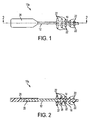
FIG. 1 is a front view of an interdental cleaner that includes an exposed support structure. -
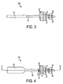
FIG. 2 is a front section view of the interdental cleaner ofFIG. 1 . -
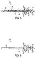
FIG. 3 is a side view of the interdental cleaner ofFIG. 1 . -
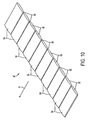
Fig. 4 is a front view of an alternative interdental cleaner that includes a sheathed support structure. -
Fig. 5 is a front section view of the interdental cleaner ofFig. 4 . -
Fig. 6 is a side view of the interdental cleaner ofFig 4 . -
Fig. 7 is a plan view of extruded material from which interdental cleaner blanks are stamped. -
Fig. 8 is a front view of an interdental cleaner blank stamped from the extruded material ofFig. 7 . -
Fig. 9 is a front view of a further interdental cleaner that is formed from the interdental cleaner blank ofFig. 8 . -
Fig. 10 is an isometric view of a further extruded material from which interdental cleaner blanks are stamped. -
Fig 11 is an isometric view of interdental cleaner blanks stamped from the extruded material ofFig. 10 . -
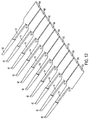
Fig. 12 is an isometric view of further alternative interdental cleaners formed from the interdental cleaner blanks ofFig. 11 , and including substantially frusto-conical cleaning heads. -
Fig. 13 is an isometric view of still further alternative interdental cleaners formed from the interdental cleaner blanks ofFig. 11 , and including substantially rectangular cleaning heads. -
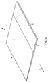
Fig. 14 is an isometric view of an embodiment of extruded material from which interdental cleaner blanks are stamped. -
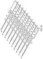
Fig. 15 is an isometric view of interdental cleaner blanks stamped from the extruded material ofFig. 14 . -
Fig. 16 is an isometric view of an embodiment of interdental cleaners formed from the interdental cleaner blanks ofFig. 14 . -
Fig. 17 is a cross-sectional view of one of the interdental cleaners ofFig. 16 taken along line 8 - 8. - It is to be understood that the invention is not limited in its application to the details of construction and the arrangements of the components set forth in the following description or embodiments, or illustrated in the drawings. The invention is capable of other embodiments and of being practiced or being carried out in various ways. Also, it is to be understood that the phraseology and terminology used herein is for the purpose of description and should not be regarded as limiting.
-
Figs. 1-3 illustrate aninterdental cleaner 10a. Theinterdental cleaner 10a includes an elongated, substantially rigidcentral rod 12, which in the illustrated construction is or includes a metallic (e.g., steel) wire. Therod 12 may be formed of, among other things, one or more braided metallic wires, solid metallic wires and/or extruded polymers or plastics, such as monofilament nylon. Theinterdental cleaner 10a includescleaning member 14 positioned at afirst end 16 of thecentral rod 12. Thecleaning member 14 is generally formed from a plastic material that is suitable for use in the mouth and that is sufficiently hard to provide cleaning of interdental spaces, but sufficiently soft so as not to damage the gums of a user. For example, in some constructions, thecleaning member 14 is formed of a thermoplastic elastomer, although other materials may also be used. Thecleaning member 14 is generally formed of a material that is softer than therod 12. - The
cleaning member 14 is formed into a shape suitable for cleaning interdental spaces. Such shapes may include, but are not limited to, conical, cylindrical, pyramidal, rectangular or polygonal in nature. In the illustrated construction, thecleaning member 14 is substantially conical in shape and includes a central, generallycylindrical body portion 18 that receives and thereby overlies thefirst end 16 of thecentral rod 12. Thecleaning member 14 also includes a plurality ofbristles 22 that extend radially outwardly from thebody portion 18. Thebristles 22 vary in length from a shortest length adjacent a distal end of thecleaning member 14, to a longest length adjacent a proximal end of thecleaning member 14, thereby providing the overall substantially conical shape. The substantially conical shape allows thecleaning member 14 to effectively clean interdental spaces of varying sizes dependent upon the extent to which a user inserts thecleaning member 14 into the interdental space. - In the illustrated construction, the
cleaning member 14 is coupled to thecentral rod 12 by over molding and/or adhesion. For an overmolding operation, thefirst end 16 of thecentral rod 12 is positioned in a mold cavity that defines the desired shape (e.g., conical) of thecleaning member 14. The cleaning member material (e.g. thermoplastic elastomer) is then injected into the mold cavity and allowed to cool around thefirst end 16. An adhesive may also be applied to thefirst end 16 before the molding process to provide additional coupling between the cleaningmember 14 and thefirst end 16. Alternatively, the cleaningmember 14 may be molded individually and thefirst end 16 of thecentral rod 12 may subsequently be inserted into thebody portion 18. Such insertion may be manual or automated, and may also involve or include the application of a suitable adhesive to one or both of the cleaningmember 14 and thecentral rod 12 to provide coupling adhesion therebetween. - The
interdental cleaner 10a also includes ahandle 26 coupled to asecond end 28 of thecentral rod 12. Thehandle 26 is generally formed from a plastic (e.g., polypropylene, including glass-filled polypropylene, and/or nylon) having a hardness that is equal to or greater than the plastic used to form the cleaningmember 14. In the illustrated construction, thehandle 26 is substantially flat and elongated to provide suitable surfaces for grasping by a user. Thehandle 26 may also be formed into any other suitable shape (e.g., cylindrical) provided that thehandle 26 is appropriately sized so as to avoid interfering with a users access to the interdental spaces while also providing for effective gripping and manipulation of the device. - Like the cleaning
member 14, thehandle 26 is generally coupled to thecentral rod 12 by overmolding and/or adhesion. For the overmolding operation, thesecond end 28 of thecentral rod 12 is inserted into a mold cavity that defines the shape of the handle 26 (e.g., flat and elongated). The mold cavity is then injected with the desired plastic for thehandle 26 and allowed to cool. Adhesives may also be applied to provide extra coupling between the end 30 and thehandle 26. Alternatively, thehandle 26 may be molded individually, and thecentral rod 12 may be inserted into thehandle 26 after the molding process. Insertion of thecentral rod 12 may be manual and/or automated. As illustrated inFigs. 1-3 , thecentral rod 12 is exposed between thehandle 26 and cleaning member14, thereby creating a central portion of the interdental cleaner that is of reduced cross section to facilitate interdental cleaning. -
Figs. 4-6 illustrate a further interdental cleaner 10b, in which thehandle 26 includes asheath portion 34 which extends along at least a portion of thecentral rod 12 toward the cleaningmember 14. Thesheath 34 covers and in some instances provides additional structural support to thecentral rod 12. In the illustrated construction, thesheath 34 extends to a location that is near but not directly adjacent to the cleaningmember 18. In other constructions thesheath 34 may extend from thehandle 26 to the cleaningmember 18 to completely cover thecentral rod 12. Thesheath 34 is generally integrally formed with thehandle 26, and, like thehandle 26, may be coupled to thecentral rod 12 by overmolding and/or adhesion, as discussed above. In other constructions, thesheath 34 and thehandle 26 may be formed separately and subsequently coupled to one another and to thecentral rod 12. It should be appreciated that substantially any sequence of assembly may be utilized during the manufacture of thehandle 26,sheath 34, and thecentral rod 12. -
Figs. 7-9 illustrate an extrusion (Fig. 7 ) that is formed into a third embodiment of an interdental cleaner 10c (Fig. 9 ). Theinterdental cleaner 10c is formed by stampingcleaner blanks 38 from an extrudedslug 42 of an extrudable material that may include, for example, polypropylene (including glass-filled polypropylene) and/or nylon. The extrudedslug 42 includes a substantially uniform thickness. After stamping, thecleaner blanks 38 are subsequently overmolded with or otherwise coupled to a cleaningmember 44. As shown inFig. 7 , thecleaner blanks 38 are preferably stamped out of theslug 42 in a pattern devised to minimize waste material. Preferably, waste material that remains after stamping of thecleaner blanks 38 is recycled for subsequent extrusion and stamping into additionalcleaner blanks 38. - As shown in
Figs. 8 and 9 , each cleaner blank 38 includes ahandle portion 46 and ashaft portion 50. Thehandle portion 46 andshaft portion 50 substantially correspond in shape and size to thehandle 26 andcentral rod 12 if theinterdental cleaners Figs. 1-6 . After thecleaner blanks 38 are stamped from the extrudedstrip 42, finishing methods such as tumbling, polishing, or deburring may be employed to remove flash and/or sharp edges from thecleaner blanks 38. Once thecleaner blanks 38 are stamped and, if necessary, finished, cleaningmembers 44 are formed on or coupled to the distal ends of theshaft portions 50 using cleaning member materials and overmolding or adhesion operations similar to those described above with respect to thecleaning members -
Figs. 10-13 illustrate a further alternative extrusion (Fig. 10 ) that is formed into a fourth embodiment of an interdental cleaner 10d (Figs. 12 and13 ).Fig. 10 illustrates an extrudedslug 60 of extrudable material that may include, for example, polypropylene (including glass-filled polypropylene) and/or nylon. Theslug 60 is extruded in the direction of the arrow N to produce a midplane P and includes a plurality ofsections 64 that extend across the width of theslug 60 and that include similar cross-sectional geometry. The cross-sectional geometry of eachsection 64 includes a relatively thickercentral portion 66, and relatively reducedthickness end portions 68. Eachsection 64 is ultimately formed into an individualinterdental cleaner 10d. - In the illustrated construction, the
slug 60 includes a substantially constant cross section in the direction of extrusion N to simplify the extrusion process. As material is extruded, theslugs 60 are cut to length in increments that substantially correspond to the length of the finished interdental cleaner, although additional material may be included to facilitate handling during trimming and/or other manufacturing processes not necessarily explained herein. -
Fig. 11 illustrates theslug 60 after a stamping process. After being extruded and/or cut to length, theslug 60 undergoes a stamping process which removes material from theslug 60 to form eachsection 64 into an individual cleaner blank 70. Each cleaner blank 70 includes ahandle portion 72 and ashaft portion 74. Formation of theshaft portion 74 may include forming a tapered portion that reduces in cross section as it extends away from thehandle portion 72. Formation of thehandle portions 72 may include the addition of grips and/or the tapering of certain edges so as to better suit the grasping process and/or enhance aesthetic appeal. Other possible alterations to thehandle portions 72 may include the addition of acompany logo 76. - In the illustrated construction, the stamping process also removes material from between
adjacent handle portions 72 to define aseparation slot 78 and a plurality of connectingtabs 80. Theslot 78 and thetabs 80 are configured to allow a plurality ofinterdental cleaners 10c to be packaged and handled as a single, continuous strip, while providing for the relatively quick and simple separation of individualinterdental cleaners 10d by breaking of thetabs 80. Theslots 78 andtabs 80 are configured so that this can be accomplished without damaging theindividual cleaners 10d and with the use of a cutting device. For example, thetabs 80 are formed in the reduced-thickness end portions 68 of theslug sections 64. -
Figs. 12 and13 illustrate strips of completedinterdental brushes 10d. After the above-described extrusion and stamping processes, cleaningmembers 82 are formed on or coupled to at least the distal ends of theshaft portions 74 using cleaning member materials and overmolding or adhesion operations similar to those described above with respect to thecleaning members cleaning members 82 are generally formed of a material that is softer than the material that forms the cleaner blanks. For example, the cleaning members may be formed of a thermoplastic elastomer. Thecleaning members 82 may be substantially conical in shape (Fig. 12 ), substantially rectangular (Fig. 13 ), or substantially any other cross-sectional shape. Although not specifically illustrated, thecleaning members 82 may also include various arrangements of bristles, such as those discussed above with respect to thecleaning members cleaning members 82. It should also be appreciated that other or additional manufacturing processes may also be employed to prepare the respectiveinterdental cleaners 10c for commercial use. Possible flash and/or other remnants of the manufacturing process may be removed by tumbling, chemical cleaning, buffing, or other processes. -
Figs. 14-17 illustrate an embodiment of an extrusion (Fig. 14 ) of the present invention that is formed into an embodiment of an interdental cleaner 10e (Figs. 16 and17 ) according to the present invention.Fig. 14 illustrates an extrudedslug 88 that is extruded in a direction of extrusion F to define a midplane P. Whereas theslug 60 ofFig. 10 is extruded in a direction that is substantially parallel with theshaft portions 74 of the resultantinterdental cleaners 10d, theslug 88 is extruded in the direction F that is substantially perpendicular to theshaft portions 74 of the resultantinterdental cleaners 10e, for reasons discussed further below. Theslug 88 includes afirst portion 90 having a substantially uniform, e.g., rectangular, constant cross section, and asecond portion 92 having a cross section that tapers toward a distal end of thesecond portion 92 that is opposite thefirst portion 90. Thesecond portion 92 also defines a first pair of converging surfaces 91 (only one of thesurfaces 91 is shown inFig. 14 ) that face away from one another and converge toward the midplane P. Although each of the illustrated first pair of convergingsurfaces 91 is substantially planar, one or both of the converging surfaces may also be curved along all or a portion of its length. - As shown in
Fig. 15 , theslug 88 is subjected to a stamping process similar to that of theslug 60, to thereby formcleaner blanks 93 that each include ahandle portion 94 formed from thefirst portion 90, and ashaft portion 96 formed from thesecond portion 92. The stamping process employed for theslug 88 may be similar to that discussed above with respect to theslug 60, and may similarly provideslots 78 andtabs 80 that allow individualinterdental cleaners 10e to be snapped off of a continuous strip ofinterdental cleaners 10e without otherwise damaging theinterdental cleaners 10e and without the use of a cutting device. As illustrated, theshaft portion 96 of each cleaner blank 93 tapers from awide end 97 adjacent thefirst portion 90 to a narrow,distal end 99 opposite thewide end 97. The taper of eachshaft portion 96 is defined by a second pair of convergingsurfaces 95 that face away from one another and that, like the convergingsurfaces 96, converge toward one another from thewide end 97 to the narrowdistal end 99. Although a majority of each of the illustrated second pair of convergingsurfaces 95 is substantially planar, one or both of the convergingsurfaces 95 may also be curved along all or a portion of its length. - As illustrated in
Fig. 16 , after thecleaner blanks 93 have been formed by the extruding and stamping operations, cleaningmembers 100 are formed on or coupled to theshaft portions 96, generally on or adjacent to the distal ends 99, using cleaning member materials and overmolding or adhesion operations similar to those described above, thereby forminginterdental cleaners 10e. It should also be appreciated that each of the manufacturing methods, materials characteristics, shapes, and bristle configurations of the various cleaning members discussed above may also be utilized for thecleaning members 100 of theinterdental cleaners 10e. - In the embodiment of
Figs. 14-17 , because theshaft portions 96 are not parallel with either the direction of extrusion or the direction of stamping, theshaft portions 96 may be formed with two pairs of converging surfaces (e.g., the first pair of convergingsurfaces 91 formed by extrusion, and the second pair of converging surfaces formed by stamping). This allows thedistal end 99 of the cleaner blank 93, and thus thedistal end 98 of the resulting interdental cleaner 10e (Fig. 16 ) to include a more sharply-defined pointed end relative to the distal ends of theinterdental cleaners
Claims (7)
- A method of making interdental cleaners (10e), the method comprising:forming a slug (88) by extruding material in a direction of extrusion (F), including forming a first slug portion (90) including a first cross-section and a second slug portion (92) including a second-cross section different from the first cross-section, the slug (88) defining a midplane (P) and the second slug portion (92) defining a first pair of converging surfaces (91) that converge toward the midplane (P);stamping the slug (88) substantially normal to the midplane (P) to form a plurality of cleaner blanks (93), each cleaner blank (93) including a handle portion (94) formed from the first slug portion (90) and a shaft portion (96) formed from the second slug portion (92), stamping the slug including forming each shaft portion (96) to include a second pair of converging surfaces (95); andattaching cleaning members (100) to a portion of the shaft portion (96).
- The method of claim 1, wherein stamping the slug (88) to form a plurality of cleaner blanks (93) further includes forming the shaft portions (96) to extend substantially perpendicular to the direction of extrusion (F).
- The method of claim 1, wherein forming the first slug portion (90) includes forming the first slug portion (90) such that the first cross-section is substantially rectangular.
- The method of claim 1, wherein the second cross-section includes a first end adjacent the first slug portion (90) and a second end opposite the first end, and wherein the second cross-section is at least partially defined by the first pair of converging surfaces (91) and tapers from the first end to the second end.
- The method of claim 1, wherein extruding the slug (88) includes extruding the slug (88) out of at least one of polypropylene and nylon.
- The method of claim 1, wherein forming a slug (88) includes forming a slug (88) of a first material, and attaching cleaning members (100) includes attaching cleaning members (100) formed of a second material that is softer than the first material, and wherein the second material is sufficiently hard to provide cleaning of interdental spaces, but sufficiently soft so as not to damage a user's gums.
- The method of claim 1, wherein attaching cleaning members (100) includes overmolding thermoplastic elastomer cleaning members over at least a portion of the shaft portion (96).
Applications Claiming Priority (2)
| Application Number | Priority Date | Filing Date | Title |
|---|---|---|---|
| US8457308P | 2008-07-29 | 2008-07-29 | |
| PCT/US2009/051979 WO2010014623A1 (en) | 2008-07-29 | 2009-07-28 | Interdental cleaners and methods for making same |
Publications (3)
| Publication Number | Publication Date |
|---|---|
| EP2306924A1 EP2306924A1 (en) | 2011-04-13 |
| EP2306924A4 EP2306924A4 (en) | 2013-04-10 |
| EP2306924B1 true EP2306924B1 (en) | 2016-09-07 |
Family
ID=41607077
Family Applications (1)
| Application Number | Title | Priority Date | Filing Date |
|---|---|---|---|
| EP09803491.1A Not-in-force EP2306924B1 (en) | 2008-07-29 | 2009-07-28 | Interdental cleaners and methods for making same |
Country Status (9)
| Country | Link |
|---|---|
| US (1) | US8663520B2 (en) |
| EP (1) | EP2306924B1 (en) |
| JP (1) | JP5215466B2 (en) |
| CN (1) | CN102123680B (en) |
| CA (1) | CA2731639C (en) |
| CO (1) | CO6341537A2 (en) |
| ES (1) | ES2594728T3 (en) |
| MX (1) | MX2011001160A (en) |
| WO (1) | WO2010014623A1 (en) |
Families Citing this family (51)
| Publication number | Priority date | Publication date | Assignee | Title |
|---|---|---|---|---|
| EP2052695B1 (en) * | 2007-10-24 | 2010-05-12 | Trisa Holding AG | Interdental tooth cleaning device |
| US20090230756A1 (en) * | 2008-03-12 | 2009-09-17 | Ranir, Llc | Interdental cleaning tool |
| TWM362682U (en) * | 2009-04-23 | 2009-08-11 | Victoria Cosmetic Co Ltd | Structure of toothpick |
| WO2011112713A2 (en) * | 2010-03-09 | 2011-09-15 | Toxcure, Inc. | Microneedle nasal delivery device |
| EP2661191B1 (en) | 2011-01-04 | 2019-06-12 | Trisa Holding AG | Toothbrush with injection-moulded bristles |
| DE102011102571A1 (en) * | 2011-05-26 | 2012-11-29 | Interbros Gmbh | Interdental cleaner set and sales unit for this |
| USD674610S1 (en) * | 2011-07-13 | 2013-01-22 | Dennis Eatherton | Interdental cleaner |
| ES2945858T3 (en) * | 2012-05-24 | 2023-07-10 | Sunstar Suisse Sa | interdental cleaning tool |
| EP4098147B1 (en) * | 2012-07-02 | 2024-12-18 | Trisa Holding AG | Interdental brush |
| DE102012015664A1 (en) * | 2012-08-09 | 2014-02-13 | Interbros Gmbh | Interdental cleaners |
| DE102012015663A1 (en) * | 2012-08-09 | 2014-05-15 | Interbros Gmbh | Interdental cleaners |
| USD744756S1 (en) * | 2012-08-30 | 2015-12-08 | Sunstar Suisse Sa | Interdental cleaning tool |
| WO2014065368A1 (en) * | 2012-10-24 | 2014-05-01 | サンスター株式会社 | Interdental cleaning tool |
| ITTO20130060U1 (en) * | 2013-04-11 | 2014-10-12 | Spada Forniture Di Spada Giuseppe | DENTAL CLEANING DEVICE. |
| DE102013010782A1 (en) * | 2013-06-28 | 2014-12-31 | Interbros Gmbh | Interdental cleaner and process for its preparation |
| US9603685B2 (en) * | 2013-09-09 | 2017-03-28 | LeedTech Resources Company, LLC | Method of manufacturing an interdental cleaner |
| US20150101633A1 (en) * | 2013-09-27 | 2015-04-16 | Bruce Goldberg | Dental hygiene tool and method |
| HUE032148T2 (en) | 2014-03-06 | 2017-09-28 | Tepe Munhygienprodukter Ab | Interdental cleaner |
| USD752221S1 (en) | 2014-03-07 | 2016-03-22 | Joannia M. Trottier | Interdental cleaning apparatus |
| US20150257861A1 (en) * | 2014-03-17 | 2015-09-17 | Ranir, Llc | Interproximal cleaning tool and method of manufacture |
| GB201409492D0 (en) * | 2014-05-28 | 2014-07-09 | Davies Rosalyn A H | Mouth care device |
| US20170319309A1 (en) * | 2014-11-11 | 2017-11-09 | Sunstar Inc. | Interdental cleaning device |
| USD787128S1 (en) * | 2015-02-13 | 2017-05-16 | Interbros Gmbh | Interdental cleaner |
| USD802137S1 (en) * | 2015-02-13 | 2017-11-07 | Interbros Gmbh | Interdental cleaner |
| USD767900S1 (en) | 2015-03-03 | 2016-10-04 | LeedTech Resources Company, LLC | Interdental brush |
| US20170239026A1 (en) * | 2015-05-21 | 2017-08-24 | Global Dent Aids Pvt. Ltd | An interdental brush with a protective tip |
| WO2016199834A1 (en) * | 2015-06-08 | 2016-12-15 | サンスター スイス エスエー | Interdental cleaning tool |
| JP6915234B2 (en) * | 2015-06-12 | 2021-08-04 | サンスター株式会社 | Intertooth cleaning tool |
| CH711664A2 (en) * | 2015-10-20 | 2017-04-28 | Pecoraro Jlena | Cleaning and disinfection stick for pierced skin holes for inserting and carrying jewelery and piercings. |
| JP1545381S (en) * | 2015-10-21 | 2019-03-04 | ||
| JP1577344S (en) * | 2015-10-21 | 2020-05-25 | ||
| JP2017119095A (en) * | 2015-12-26 | 2017-07-06 | サンスター株式会社 | Interdental cleaner and manufacturing process thereof |
| JP6292246B2 (en) * | 2016-03-07 | 2018-03-14 | サンスター株式会社 | Interdental cleaning tool |
| JP6281586B2 (en) * | 2016-03-07 | 2018-02-21 | サンスター株式会社 | Interdental cleaning tool |
| JP6812124B2 (en) * | 2016-03-30 | 2021-01-13 | 小林製薬株式会社 | Interdental cleaning tool group |
| CN106108360A (en) * | 2016-08-09 | 2016-11-16 | 扬州华腾个人护理用品有限公司 | Interdental brush and manufacture method thereof |
| USD843063S1 (en) | 2017-04-04 | 2019-03-12 | Dentek Oral Care, Inc. | Interdental pick |
| USD846806S1 (en) | 2017-04-04 | 2019-04-23 | DenTek Oral Care, Inc | Interdental pick set |
| USD838910S1 (en) | 2017-04-04 | 2019-01-22 | Dentek Oral Care, Inc. | Interdental pick set with frame |
| USD838909S1 (en) | 2017-04-04 | 2019-01-22 | Dentek Oral Care, Inc. | Interdental pick |
| USD843062S1 (en) | 2017-04-04 | 2019-03-12 | Dentek Oral Care, Inc. | Interdental pick |
| USD843061S1 (en) | 2017-04-04 | 2019-03-12 | DenTek Oral Care, Inc | Interdental Pick |
| DE102017010561A1 (en) * | 2017-11-15 | 2019-05-16 | Interbros Gmbh | Interdental cleaner |
| DE102018002147B3 (en) * | 2018-03-16 | 2019-06-13 | Interbros Gmbh | Interdental cleaner |
| JP7449038B2 (en) * | 2018-06-29 | 2024-03-13 | 小林製薬株式会社 | Interdental cleaning tool |
| JP7417353B2 (en) | 2018-12-28 | 2024-01-18 | 小林製薬株式会社 | Manufacturing method for interdental cleaning tools |
| JP2020103851A (en) | 2018-12-28 | 2020-07-09 | 小林製薬株式会社 | Interdental cleaning tool |
| JP7652528B2 (en) * | 2018-12-28 | 2025-03-27 | 小林製薬株式会社 | Interdental Cleaning Tools |
| US11980514B2 (en) * | 2019-10-23 | 2024-05-14 | Doctor Staci, Llc | Flossing apparatus |
| DE102020100234A1 (en) * | 2020-01-08 | 2021-07-08 | Interbros Gmbh | Interdental cleaner |
| JP7395798B2 (en) * | 2020-06-04 | 2023-12-12 | 和博 川崎 | Two-material interdental cleaning tool |
Family Cites Families (31)
| Publication number | Priority date | Publication date | Assignee | Title |
|---|---|---|---|---|
| US1527845A (en) | 1924-08-21 | 1925-02-24 | Daniel Hal Speed | Toothpick |
| US1581501A (en) | 1925-03-11 | 1926-04-20 | Albert E Wright | Tooth cleaner |
| US1746591A (en) | 1929-07-23 | 1930-02-11 | George H Heymann | Toothpick |
| US3078856A (en) | 1961-01-05 | 1963-02-26 | Bender Harry | Disposable dental implement |
| US3590814A (en) * | 1969-01-03 | 1971-07-06 | Johnson & Johnson | Interdental stimulator |
| US3779256A (en) | 1971-10-20 | 1973-12-18 | A Maloney | Oral hygienic device |
| US3775848A (en) | 1972-11-03 | 1973-12-04 | E Barnett | Periodontal and dental cleanser and periodontal stimulator |
| US4319377A (en) | 1980-08-25 | 1982-03-16 | John O. Butler Company | Interproximal toothbrush |
| US4326547A (en) | 1980-11-03 | 1982-04-27 | Verplank C Michael | Tooth probe device |
| JPS6038272U (en) * | 1983-08-23 | 1985-03-16 | 今川 和男 | toothpick set |
| JPH0229939Y2 (en) * | 1985-04-24 | 1990-08-13 | ||
| US4832063A (en) | 1987-10-09 | 1989-05-23 | Smole Frederick T | Flossing device |
| US4974615A (en) | 1989-07-26 | 1990-12-04 | Doundoulakis George J | Elastic filament for oral hygiene |
| JPH0432706U (en) * | 1990-07-16 | 1992-03-17 | ||
| US5246021A (en) | 1992-02-14 | 1993-09-21 | Katz Harry S | Disposable floss pick and method of manufacture |
| US5392794A (en) * | 1993-11-18 | 1995-02-28 | Striebel; John S. | Dental floss for brace wearers and the like |
| SE502623C2 (en) * | 1994-10-12 | 1995-11-27 | Leif Einar Stern | Toothpicks and process for making them |
| US5987688A (en) | 1995-11-09 | 1999-11-23 | Gillette Canada Inc. | Gum-massaging oral brush |
| US5775346A (en) | 1996-02-14 | 1998-07-07 | Advanced Implant Technologies Inc. | Interproximal dental appliances |
| JPH105250A (en) * | 1996-06-21 | 1998-01-13 | Kao Corp | Toothpick |
| DE19642431A1 (en) * | 1996-10-15 | 1998-04-16 | Coronet Werke Gmbh | Interdental cleaner and process for its manufacture |
| US5806540A (en) | 1996-11-18 | 1998-09-15 | Lee; Wan K. | Tooth pick with flexible hollow body |
| JPH11192245A (en) | 1997-12-26 | 1999-07-21 | Lion Corp | Interdental cleaning tool |
| JP3824041B2 (en) | 1998-12-04 | 2006-09-20 | 株式会社三▲しゅう▼プレシジョン | Interdental cleaning tool and manufacturing method thereof |
| US6220258B1 (en) * | 1999-03-15 | 2001-04-24 | Robert B. Briggs | Extruded plastic toothpick and method |
| US6609910B2 (en) * | 1999-11-19 | 2003-08-26 | Water Pik, Inc. | Tip for dental flossing device |
| WO2002015814A1 (en) | 2000-08-23 | 2002-02-28 | Hill Ira D | Physical improvements in coated monofilament dental tapes |
| US6669475B2 (en) * | 2002-06-03 | 2003-12-30 | Stanislas Kandelman | Personal interproximal dental surface cleaning and drug delivery device |
| US7578954B2 (en) * | 2003-02-24 | 2009-08-25 | Corium International, Inc. | Method for manufacturing microstructures having multiple microelements with through-holes |
| JP4581716B2 (en) | 2005-02-02 | 2010-11-17 | サンスター株式会社 | Interdental cleaning tool and manufacturing method thereof |
| US7854235B2 (en) * | 2007-03-21 | 2010-12-21 | Mcneil-Ppc, Inc. | Dental tape and process for obtaining a dental tape |
-
2009
- 2009-07-28 WO PCT/US2009/051979 patent/WO2010014623A1/en not_active Ceased
- 2009-07-28 CA CA2731639A patent/CA2731639C/en not_active Expired - Fee Related
- 2009-07-28 CN CN200980132870.1A patent/CN102123680B/en not_active Expired - Fee Related
- 2009-07-28 JP JP2011521249A patent/JP5215466B2/en not_active Expired - Fee Related
- 2009-07-28 US US12/510,852 patent/US8663520B2/en not_active Expired - Fee Related
- 2009-07-28 MX MX2011001160A patent/MX2011001160A/en active IP Right Grant
- 2009-07-28 EP EP09803491.1A patent/EP2306924B1/en not_active Not-in-force
- 2009-07-28 ES ES09803491.1T patent/ES2594728T3/en active Active
-
2011
- 2011-01-28 CO CO11009800A patent/CO6341537A2/en active IP Right Grant
Non-Patent Citations (1)
| Title |
|---|
| None * |
Also Published As
| Publication number | Publication date |
|---|---|
| US20100024839A1 (en) | 2010-02-04 |
| US8663520B2 (en) | 2014-03-04 |
| WO2010014623A1 (en) | 2010-02-04 |
| JP5215466B2 (en) | 2013-06-19 |
| CN102123680B (en) | 2014-04-16 |
| CA2731639A1 (en) | 2010-02-04 |
| CN102123680A (en) | 2011-07-13 |
| CA2731639C (en) | 2015-06-02 |
| MX2011001160A (en) | 2011-04-26 |
| EP2306924A1 (en) | 2011-04-13 |
| JP2011529729A (en) | 2011-12-15 |
| CO6341537A2 (en) | 2011-11-21 |
| EP2306924A4 (en) | 2013-04-10 |
| ES2594728T3 (en) | 2016-12-22 |
| WO2010014623A8 (en) | 2010-10-21 |
Similar Documents
| Publication | Publication Date | Title |
|---|---|---|
| CA2731639C (en) | Interdental cleaners and methods for making same | |
| CA3058912C (en) | Oral care implement and method for manufacturing such oral care implement | |
| US6003525A (en) | Elastomer floss and related flossing devices | |
| EP2100570A1 (en) | Interdental cleaning tool | |
| US10231808B2 (en) | Method of using a bristled toothpick assembly | |
| WO2016154733A1 (en) | Multi-function flosser | |
| US10898303B2 (en) | Three-in-one tooth-cleaning device structured as toothpick, interdental brush, and floss pick | |
| JP2021151493A (en) | Oral cleaning implement with tool adapted for removal of denture adhesive from dentures | |
| JP5960230B2 (en) | Automatic rotating interdental brush | |
| US20120138083A1 (en) | Dental floss device for cleaning teeth and neutralizing bad breath | |
| AU2018250811B2 (en) | Oral care implement and method for manafacturing such oral care implement | |
| JP3255554U (en) | Interdental cleaning tools | |
| CN218391313U (en) | Double-wedge-shaped-head multifunctional toothpick | |
| JP3129329U (en) | Dental products with holder | |
| JP4753394B2 (en) | Toothbrush bristle material and toothbrush | |
| JP2004174110A (en) | Floss pick | |
| KR200323733Y1 (en) | A tongue scrubbing things | |
| KR100697186B1 (en) | Toothpicks equipped with a brush and a method of manufacturing the same | |
| KR102120282B1 (en) | Toothbrush | |
| JPH11137577A (en) | Interdental cleaning tool | |
| CN115734724A (en) | Handles for personal care implements and personal care implements | |
| HK1254441A1 (en) | Bristled dental floss |
Legal Events
| Date | Code | Title | Description |
|---|---|---|---|
| PUAI | Public reference made under article 153(3) epc to a published international application that has entered the european phase |
Free format text: ORIGINAL CODE: 0009012 |
|
| 17P | Request for examination filed |
Effective date: 20110131 |
|
| AK | Designated contracting states |
Kind code of ref document: A1 Designated state(s): AT BE BG CH CY CZ DE DK EE ES FI FR GB GR HR HU IE IS IT LI LT LU LV MC MK MT NL NO PL PT RO SE SI SK SM TR |
|
| AX | Request for extension of the european patent |
Extension state: AL BA RS |
|
| RAP1 | Party data changed (applicant data changed or rights of an application transferred) |
Owner name: SUNSTAR SUISSE, S.A. |
|
| DAX | Request for extension of the european patent (deleted) | ||
| REG | Reference to a national code |
Ref country code: DE Ref legal event code: R079 Ref document number: 602009041022 Country of ref document: DE Free format text: PREVIOUS MAIN CLASS: A61C0015000000 Ipc: A61C0015020000 |
|
| A4 | Supplementary search report drawn up and despatched |
Effective date: 20130307 |
|
| RIC1 | Information provided on ipc code assigned before grant |
Ipc: A61C 15/02 20060101AFI20130301BHEP Ipc: A46B 1/00 20060101ALI20130301BHEP |
|
| 17Q | First examination report despatched |
Effective date: 20150605 |
|
| GRAP | Despatch of communication of intention to grant a patent |
Free format text: ORIGINAL CODE: EPIDOSNIGR1 |
|
| INTG | Intention to grant announced |
Effective date: 20160128 |
|
| GRAR | Information related to intention to grant a patent recorded |
Free format text: ORIGINAL CODE: EPIDOSNIGR71 |
|
| GRAS | Grant fee paid |
Free format text: ORIGINAL CODE: EPIDOSNIGR3 |
|
| INTG | Intention to grant announced |
Effective date: 20160621 |
|
| GRAA | (expected) grant |
Free format text: ORIGINAL CODE: 0009210 |
|
| AK | Designated contracting states |
Kind code of ref document: B1 Designated state(s): AT BE BG CH CY CZ DE DK EE ES FI FR GB GR HR HU IE IS IT LI LT LU LV MC MK MT NL NO PL PT RO SE SI SK SM TR |
|
| REG | Reference to a national code |
Ref country code: GB Ref legal event code: FG4D |
|
| REG | Reference to a national code |
Ref country code: CH Ref legal event code: EP |
|
| REG | Reference to a national code |
Ref country code: CH Ref legal event code: NV Representative=s name: MARKS AND CLERK (LUXEMBOURG) LLP, CH |
|
| REG | Reference to a national code |
Ref country code: IE Ref legal event code: FG4D |
|
| REG | Reference to a national code |
Ref country code: AT Ref legal event code: REF Ref document number: 826128 Country of ref document: AT Kind code of ref document: T Effective date: 20161015 |
|
| REG | Reference to a national code |
Ref country code: DE Ref legal event code: R096 Ref document number: 602009041022 Country of ref document: DE |
|
| REG | Reference to a national code |
Ref country code: SE Ref legal event code: TRGR |
|
| REG | Reference to a national code |
Ref country code: ES Ref legal event code: FG2A Ref document number: 2594728 Country of ref document: ES Kind code of ref document: T3 Effective date: 20161222 |
|
| REG | Reference to a national code |
Ref country code: LT Ref legal event code: MG4D |
|
| REG | Reference to a national code |
Ref country code: NL Ref legal event code: MP Effective date: 20160907 |
|
| PG25 | Lapsed in a contracting state [announced via postgrant information from national office to epo] |
Ref country code: HR Free format text: LAPSE BECAUSE OF FAILURE TO SUBMIT A TRANSLATION OF THE DESCRIPTION OR TO PAY THE FEE WITHIN THE PRESCRIBED TIME-LIMIT Effective date: 20160907 Ref country code: FI Free format text: LAPSE BECAUSE OF FAILURE TO SUBMIT A TRANSLATION OF THE DESCRIPTION OR TO PAY THE FEE WITHIN THE PRESCRIBED TIME-LIMIT Effective date: 20160907 Ref country code: NO Free format text: LAPSE BECAUSE OF FAILURE TO SUBMIT A TRANSLATION OF THE DESCRIPTION OR TO PAY THE FEE WITHIN THE PRESCRIBED TIME-LIMIT Effective date: 20161207 Ref country code: LT Free format text: LAPSE BECAUSE OF FAILURE TO SUBMIT A TRANSLATION OF THE DESCRIPTION OR TO PAY THE FEE WITHIN THE PRESCRIBED TIME-LIMIT Effective date: 20160907 |
|
| REG | Reference to a national code |
Ref country code: AT Ref legal event code: MK05 Ref document number: 826128 Country of ref document: AT Kind code of ref document: T Effective date: 20160907 |
|
| PG25 | Lapsed in a contracting state [announced via postgrant information from national office to epo] |
Ref country code: LV Free format text: LAPSE BECAUSE OF FAILURE TO SUBMIT A TRANSLATION OF THE DESCRIPTION OR TO PAY THE FEE WITHIN THE PRESCRIBED TIME-LIMIT Effective date: 20160907 Ref country code: NL Free format text: LAPSE BECAUSE OF FAILURE TO SUBMIT A TRANSLATION OF THE DESCRIPTION OR TO PAY THE FEE WITHIN THE PRESCRIBED TIME-LIMIT Effective date: 20160907 Ref country code: GR Free format text: LAPSE BECAUSE OF FAILURE TO SUBMIT A TRANSLATION OF THE DESCRIPTION OR TO PAY THE FEE WITHIN THE PRESCRIBED TIME-LIMIT Effective date: 20161208 |
|
| PG25 | Lapsed in a contracting state [announced via postgrant information from national office to epo] |
Ref country code: EE Free format text: LAPSE BECAUSE OF FAILURE TO SUBMIT A TRANSLATION OF THE DESCRIPTION OR TO PAY THE FEE WITHIN THE PRESCRIBED TIME-LIMIT Effective date: 20160907 Ref country code: RO Free format text: LAPSE BECAUSE OF FAILURE TO SUBMIT A TRANSLATION OF THE DESCRIPTION OR TO PAY THE FEE WITHIN THE PRESCRIBED TIME-LIMIT Effective date: 20160907 |
|
| PG25 | Lapsed in a contracting state [announced via postgrant information from national office to epo] |
Ref country code: CZ Free format text: LAPSE BECAUSE OF FAILURE TO SUBMIT A TRANSLATION OF THE DESCRIPTION OR TO PAY THE FEE WITHIN THE PRESCRIBED TIME-LIMIT Effective date: 20160907 Ref country code: PT Free format text: LAPSE BECAUSE OF FAILURE TO SUBMIT A TRANSLATION OF THE DESCRIPTION OR TO PAY THE FEE WITHIN THE PRESCRIBED TIME-LIMIT Effective date: 20170109 Ref country code: SK Free format text: LAPSE BECAUSE OF FAILURE TO SUBMIT A TRANSLATION OF THE DESCRIPTION OR TO PAY THE FEE WITHIN THE PRESCRIBED TIME-LIMIT Effective date: 20160907 Ref country code: BE Free format text: LAPSE BECAUSE OF FAILURE TO SUBMIT A TRANSLATION OF THE DESCRIPTION OR TO PAY THE FEE WITHIN THE PRESCRIBED TIME-LIMIT Effective date: 20160907 Ref country code: IS Free format text: LAPSE BECAUSE OF FAILURE TO SUBMIT A TRANSLATION OF THE DESCRIPTION OR TO PAY THE FEE WITHIN THE PRESCRIBED TIME-LIMIT Effective date: 20170107 Ref country code: SM Free format text: LAPSE BECAUSE OF FAILURE TO SUBMIT A TRANSLATION OF THE DESCRIPTION OR TO PAY THE FEE WITHIN THE PRESCRIBED TIME-LIMIT Effective date: 20160907 Ref country code: AT Free format text: LAPSE BECAUSE OF FAILURE TO SUBMIT A TRANSLATION OF THE DESCRIPTION OR TO PAY THE FEE WITHIN THE PRESCRIBED TIME-LIMIT Effective date: 20160907 Ref country code: BG Free format text: LAPSE BECAUSE OF FAILURE TO SUBMIT A TRANSLATION OF THE DESCRIPTION OR TO PAY THE FEE WITHIN THE PRESCRIBED TIME-LIMIT Effective date: 20161207 Ref country code: PL Free format text: LAPSE BECAUSE OF FAILURE TO SUBMIT A TRANSLATION OF THE DESCRIPTION OR TO PAY THE FEE WITHIN THE PRESCRIBED TIME-LIMIT Effective date: 20160907 |
|
| REG | Reference to a national code |
Ref country code: DE Ref legal event code: R097 Ref document number: 602009041022 Country of ref document: DE |
|
| PLBE | No opposition filed within time limit |
Free format text: ORIGINAL CODE: 0009261 |
|
| STAA | Information on the status of an ep patent application or granted ep patent |
Free format text: STATUS: NO OPPOSITION FILED WITHIN TIME LIMIT |
|
| REG | Reference to a national code |
Ref country code: FR Ref legal event code: PLFP Year of fee payment: 9 |
|
| PG25 | Lapsed in a contracting state [announced via postgrant information from national office to epo] |
Ref country code: DK Free format text: LAPSE BECAUSE OF FAILURE TO SUBMIT A TRANSLATION OF THE DESCRIPTION OR TO PAY THE FEE WITHIN THE PRESCRIBED TIME-LIMIT Effective date: 20160907 |
|
| 26N | No opposition filed |
Effective date: 20170608 |
|
| PG25 | Lapsed in a contracting state [announced via postgrant information from national office to epo] |
Ref country code: SI Free format text: LAPSE BECAUSE OF FAILURE TO SUBMIT A TRANSLATION OF THE DESCRIPTION OR TO PAY THE FEE WITHIN THE PRESCRIBED TIME-LIMIT Effective date: 20160907 |
|
| PGFP | Annual fee paid to national office [announced via postgrant information from national office to epo] |
Ref country code: IT Payment date: 20170725 Year of fee payment: 9 Ref country code: ES Payment date: 20170801 Year of fee payment: 9 Ref country code: GB Payment date: 20170727 Year of fee payment: 9 Ref country code: FR Payment date: 20170726 Year of fee payment: 9 Ref country code: DE Payment date: 20170727 Year of fee payment: 9 Ref country code: CH Payment date: 20170727 Year of fee payment: 9 |
|
| PGFP | Annual fee paid to national office [announced via postgrant information from national office to epo] |
Ref country code: SE Payment date: 20170727 Year of fee payment: 9 |
|
| REG | Reference to a national code |
Ref country code: IE Ref legal event code: MM4A |
|
| PG25 | Lapsed in a contracting state [announced via postgrant information from national office to epo] |
Ref country code: IE Free format text: LAPSE BECAUSE OF NON-PAYMENT OF DUE FEES Effective date: 20170728 |
|
| PG25 | Lapsed in a contracting state [announced via postgrant information from national office to epo] |
Ref country code: LU Free format text: LAPSE BECAUSE OF NON-PAYMENT OF DUE FEES Effective date: 20170728 |
|
| PG25 | Lapsed in a contracting state [announced via postgrant information from national office to epo] |
Ref country code: MT Free format text: LAPSE BECAUSE OF NON-PAYMENT OF DUE FEES Effective date: 20170728 |
|
| REG | Reference to a national code |
Ref country code: DE Ref legal event code: R119 Ref document number: 602009041022 Country of ref document: DE |
|
| REG | Reference to a national code |
Ref country code: CH Ref legal event code: PL |
|
| GBPC | Gb: european patent ceased through non-payment of renewal fee |
Effective date: 20180728 |
|
| PG25 | Lapsed in a contracting state [announced via postgrant information from national office to epo] |
Ref country code: LI Free format text: LAPSE BECAUSE OF NON-PAYMENT OF DUE FEES Effective date: 20180731 Ref country code: FR Free format text: LAPSE BECAUSE OF NON-PAYMENT OF DUE FEES Effective date: 20180731 Ref country code: CH Free format text: LAPSE BECAUSE OF NON-PAYMENT OF DUE FEES Effective date: 20180731 Ref country code: DE Free format text: LAPSE BECAUSE OF NON-PAYMENT OF DUE FEES Effective date: 20190201 Ref country code: GB Free format text: LAPSE BECAUSE OF NON-PAYMENT OF DUE FEES Effective date: 20180728 |
|
| PG25 | Lapsed in a contracting state [announced via postgrant information from national office to epo] |
Ref country code: SE Free format text: LAPSE BECAUSE OF NON-PAYMENT OF DUE FEES Effective date: 20180729 |
|
| PG25 | Lapsed in a contracting state [announced via postgrant information from national office to epo] |
Ref country code: MC Free format text: LAPSE BECAUSE OF FAILURE TO SUBMIT A TRANSLATION OF THE DESCRIPTION OR TO PAY THE FEE WITHIN THE PRESCRIBED TIME-LIMIT Effective date: 20160907 Ref country code: HU Free format text: LAPSE BECAUSE OF FAILURE TO SUBMIT A TRANSLATION OF THE DESCRIPTION OR TO PAY THE FEE WITHIN THE PRESCRIBED TIME-LIMIT; INVALID AB INITIO Effective date: 20090728 |
|
| PG25 | Lapsed in a contracting state [announced via postgrant information from national office to epo] |
Ref country code: IT Free format text: LAPSE BECAUSE OF NON-PAYMENT OF DUE FEES Effective date: 20180728 |
|
| REG | Reference to a national code |
Ref country code: ES Ref legal event code: FD2A Effective date: 20190917 |
|
| PG25 | Lapsed in a contracting state [announced via postgrant information from national office to epo] |
Ref country code: ES Free format text: LAPSE BECAUSE OF NON-PAYMENT OF DUE FEES Effective date: 20180729 Ref country code: CY Free format text: LAPSE BECAUSE OF NON-PAYMENT OF DUE FEES Effective date: 20160907 |
|
| PG25 | Lapsed in a contracting state [announced via postgrant information from national office to epo] |
Ref country code: MK Free format text: LAPSE BECAUSE OF FAILURE TO SUBMIT A TRANSLATION OF THE DESCRIPTION OR TO PAY THE FEE WITHIN THE PRESCRIBED TIME-LIMIT Effective date: 20160907 |
|
| PG25 | Lapsed in a contracting state [announced via postgrant information from national office to epo] |
Ref country code: TR Free format text: LAPSE BECAUSE OF FAILURE TO SUBMIT A TRANSLATION OF THE DESCRIPTION OR TO PAY THE FEE WITHIN THE PRESCRIBED TIME-LIMIT Effective date: 20160907 |