EP2306585A1 - Method and apparatus for preventing energy leakage from electrical transmission lines - Google Patents
Method and apparatus for preventing energy leakage from electrical transmission lines Download PDFInfo
- Publication number
- EP2306585A1 EP2306585A1 EP20100176896 EP10176896A EP2306585A1 EP 2306585 A1 EP2306585 A1 EP 2306585A1 EP 20100176896 EP20100176896 EP 20100176896 EP 10176896 A EP10176896 A EP 10176896A EP 2306585 A1 EP2306585 A1 EP 2306585A1
- Authority
- EP
- European Patent Office
- Prior art keywords
- flow rate
- gas
- gas pressure
- transmission line
- pressure
- Prior art date
- Legal status (The legal status is an assumption and is not a legal conclusion. Google has not performed a legal analysis and makes no representation as to the accuracy of the status listed.)
- Granted
Links
Images


Classifications
-
- H—ELECTRICITY
- H01—ELECTRIC ELEMENTS
- H01P—WAVEGUIDES; RESONATORS, LINES, OR OTHER DEVICES OF THE WAVEGUIDE TYPE
- H01P1/00—Auxiliary devices
- H01P1/30—Auxiliary devices for compensation of, or protection against, temperature or moisture effects ; for improving power handling capability
-
- H—ELECTRICITY
- H01—ELECTRIC ELEMENTS
- H01P—WAVEGUIDES; RESONATORS, LINES, OR OTHER DEVICES OF THE WAVEGUIDE TYPE
- H01P3/00—Waveguides; Transmission lines of the waveguide type
- H01P3/12—Hollow waveguides
-
- Y—GENERAL TAGGING OF NEW TECHNOLOGICAL DEVELOPMENTS; GENERAL TAGGING OF CROSS-SECTIONAL TECHNOLOGIES SPANNING OVER SEVERAL SECTIONS OF THE IPC; TECHNICAL SUBJECTS COVERED BY FORMER USPC CROSS-REFERENCE ART COLLECTIONS [XRACs] AND DIGESTS
- Y10—TECHNICAL SUBJECTS COVERED BY FORMER USPC
- Y10T—TECHNICAL SUBJECTS COVERED BY FORMER US CLASSIFICATION
- Y10T137/00—Fluid handling
- Y10T137/0318—Processes
- Y10T137/0324—With control of flow by a condition or characteristic of a fluid
- Y10T137/0379—By fluid pressure
-
- Y—GENERAL TAGGING OF NEW TECHNOLOGICAL DEVELOPMENTS; GENERAL TAGGING OF CROSS-SECTIONAL TECHNOLOGIES SPANNING OVER SEVERAL SECTIONS OF THE IPC; TECHNICAL SUBJECTS COVERED BY FORMER USPC CROSS-REFERENCE ART COLLECTIONS [XRACs] AND DIGESTS
- Y10—TECHNICAL SUBJECTS COVERED BY FORMER USPC
- Y10T—TECHNICAL SUBJECTS COVERED BY FORMER US CLASSIFICATION
- Y10T137/00—Fluid handling
- Y10T137/8376—Combined
Definitions
- Transmission line designs vary considerably depending on the geometry between the source and destination, and the frequency and energy level of the electrical energy.
- microwave energy is often transmitted via a closed waveguide resembling a rectangular pipe.
- a microwave transmission line is fabricated from various waveguide sections and microwave modification components that are connected together to transmit energy from the source to the destination.
- Another conventional approach is to enclose the transmission line components in a protective metal enclosure. Although this approach ensures no energy leakage beyond the enclosure, it does not detect transmission line misalignment, which could affect equipment operation and energy transmission efficiency. In addition, if part of the transmission line must be removable, there is no mechanism for ensuring that the removable part is re-attached before enabling the energy source.
- Still another approach is to use either mechanical or optical switches attached to the transmission line components to ensure correct component placement.
- switches it is difficult to position and connect enough switches to verify correct placement of the components, especially if portions of the line are removable.
- Another concern is the ease with which switches can be bypassed or overridden.
- a further approach is to use a light curtain or proximity sensors. This requires multiple detectors to cover the area in which the transmission system is located and is costly. In addition, the sensors can detect when personnel or objects enter the area near the transmission system, but do not address component misalignment and associated potential energy leakage.
- the transmission line is treated as a "partially closed" vessel.
- a gas stream with a pressure slightly different from ambient pressure is provided to the interior of the transmission line and a conduit between the transmission line and the surrounding environment is provided to allow gas to pass between the interior of the transmission line and the ambient environment.
- the gas flow rate at the conduit is then detected and monitored. If the flow rate falls outside a predetermined threshold, an electrical energy leakage is indicated.
- This method can compensate for small steady state leaks along the transmission line assembly, and monitors for misalignment throughout the length of the transmission line.
- the pressure of the input gas to the transmission line is continuously checked by a pressure switch, which will detect a change in pressure if the transmission integrity is compromised and disable the energy source.
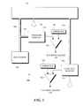
- Figure 1 is a block schematic diagram showing the inventive transmission line integrity monitoring apparatus.
- Figure 2 is a flowchart illustrating steps in an illustrative method for preventing energy leakage from electrical transmission lines.
- Figure 3 is a schematic diagram showing an application of the energy leakage monitoring apparatus to a waveguide of a nuclear magnetic resonance system.
- Figure 1 illustrates the apparatus that comprises the inventive monitoring system 100 and Figure 2 is a flowchart showing the steps in a method for its use.
- the transmission line including all components connected between the electrical energy source and the energy destination or any subset thereof, is treated as a partially closed vessel 102.
- a partially closed vessel is a closed vessel in which at least one steady state leak exists.
- all steady state leaks in the system are treated together and shown as cumulative leak 104.
- the method for monitoring transmission line electrical integrity begins in step 200 and proceeds to step 202 where gas from gas source 106 is injected into the transmission line 102 via gas input 108.
- This gas is typically at a pressure slightly different from ambient pressure. This pressure can be either slightly above ambient pressure or slightly below ambient pressure. In the discussion below, it is assumed that this pressure is slightly above ambient pressure. However, those skilled in the art would understand that a pressure slightly below ambient pressure could also be used without departing from the principles of the invention. In one embodiment, the gas pressure is 1.5 PSI to 3.5 PSI.
- a gas pressure monitor 112 is attached to gas input 108, for example, by connection 110 as shown in Figure 1 . The gas exits the transmission line system 102 via a gas conduit 114.
- the gas conduit 114 is connected to a gas flow rate monitor 116 through which the gas flows before finally exiting the system at 118.
- Figure 1 shows the gas as exiting at 118 to the atmosphere, those skilled in the art would understand that other arrangement could be made for the gas exhaust.
- step 204 at the time of installation of the monitoring system, the input gas pressure is adjusted so that the exhaust gas flow rate from the transmission line is equal to a predetermined minimum amount, for example 1 SLPM. This adjustment compensates for small steady-state gas leaks 104 in each transmission line assembly.
- step 206 during operation, the gas flow monitor 116 continuously monitors the exhaust gas flow rate. Any misalignment or displacement between transmission line components allows additional gas to escape, thus reducing gas flow through the flow rate monitor 116.
- the output of flow rate monitor 116 is connected to a comparator 122 which compares the output to a predetermined minimum flow rate threshold 120, which may, for example, be set to approximately 1 SLPM. If exhaust flow rate monitor output signal falls below the minimum flow rate threshold as determined in step 210, the comparator output signal changes state and, in step 214, shuts off the energy source until the transmission line misalignment is corrected. The method then ends in step 216.
- a predetermined minimum flow rate threshold 120 which may, for example, be set to approximately 1 SLPM.
- step 210 if in step 210, it is determined that the exhaust gas flow rate detected by monitor 116 is not below the threshold, then the method returns to step 206 to continue monitoring the exhaust gas flow rate.
- the pressure of the input gas to the transmission line is continuously checked in step 208 by a pressure monitor 112.
- the output of the pressure monitor 112 is connected to a comparator 128 which compares it to a minimum pressure threshold 126. If the transmission line integrity is compromised, the output of the pressure monitor 112 will fall below the threshold as detected in step 212 and the energy source will be shut off as indicated in step 214. The method then ends in step 216.
- the comparator 128 could be replaced with an equivalent mechanical or electromechanical mechanism.
- step 212 if in step 212, it is determined that the input gas pressure detected by monitor 112 is not below the threshold, then the method returns to step 206 to continue monitoring the input gas pressure.
- FIG 3 illustrates the application of the inventive monitoring apparatus to a microwave waveguide used in a nuclear magnetic resonance apparatus 300.
- the microwave waveguide comprises a plurality of components, including waveguide sections 302, 306, 310, 314 and 316.
- the waveguide sections are connected together by corner connectors 308, 312 and 318.
- Other components may include attenuators 304 and 320.
- the waveguide conducts microwave energy from a microwave source located at the right side of the figure (not shown in Figure 3 ) and connected to waveguide section 302 to the NMR probe 322 at the left side of the figure.
- the waveguide is supported on a conductive stand comprising bed 324 and riser 326.
- Pressurized gas from gas source 328 (not shown in Figure 3 ) is applied to a pressure regulator 332 to reduce the source pressure to a constant low pressure. This pressure can be monitored via pressure gauge 334.
- the low pressure gas is provided via conduit 338 to a coupler 342 connected between waveguide sections 314 and 316. The coupler 342 injects the pressurized gas into the interior of the waveguide transmission line.
- the coupler 342 also allows gas to exit the transmission line via conduit 344.
- Conduit 344 is, in turn, connected to gas flow rate monitor 346.
- the exhaust gas exits the flow rate monitor 346 via conduit 348 to a gas exhaust 350 (not shown in Figure 3 ).
- the flow rate monitor 346 provides flow rate signals to the signal conditioning electronics 340.
- the pressure switch 336 detects this condition and notifies signal conditioning electronics 340.
- Signal conditioning electronics 340 generates a flow rate signal 352 when the exhaust gas flow rate falls below a predetermined minimum flow rate threshold.
- Signal conditioning electronics 340 also generates a gas pressure signal 354 when the pressure switch 336 indicates that the input gas pressure has fallen below the predetermined minimum gas pressure threshold. Either signal 352 or 354 can be used to turn off the microwave energy source.
- the inventive system can thus detect waveguide misalignment and integrity breaches. In addition, a failure in the pressurized gas source will also be detected.
Landscapes
- Examining Or Testing Airtightness (AREA)
- Measuring Volume Flow (AREA)
Abstract
Description
- Electrical energy is often transmitted from a source to a destination via a waveguide or transmission line. Transmission line designs vary considerably depending on the geometry between the source and destination, and the frequency and energy level of the electrical energy. For example, microwave energy is often transmitted via a closed waveguide resembling a rectangular pipe. Typically, a microwave transmission line is fabricated from various waveguide sections and microwave modification components that are connected together to transmit energy from the source to the destination.
- The proper alignment of the transmission line sections and components is critical for efficient electrical energy transmission. In addition, any misalignment between transmission line components creates the potential for energy leakage. In some cases, excessive energy leakage levels can present a hazard to personnel or equipment.
- Various conventional methods have been used to either detect energy leakage or to prevent injury to personnel and equipment if such leakage does occur. For example, one common approach is to physically secure the area where the transmission system is located. This approach is often impractical where the transmission system is too large to be enclosed or where it is necessary to an operator be present to operate the system. In addition, such an arrangement would effectively require a mechanism that disables the energy source when personnel are present. Further, without special construction, conventional walls or doors may not prohibit energy transmission.
- Another conventional approach is to enclose the transmission line components in a protective metal enclosure. Although this approach ensures no energy leakage beyond the enclosure, it does not detect transmission line misalignment, which could affect equipment operation and energy transmission efficiency. In addition, if part of the transmission line must be removable, there is no mechanism for ensuring that the removable part is re-attached before enabling the energy source.
- Still another approach is to use either mechanical or optical switches attached to the transmission line components to ensure correct component placement. However, in systems with numerous components, it is difficult to position and connect enough switches to verify correct placement of the components, especially if portions of the line are removable. Another concern is the ease with which switches can be bypassed or overridden.
- Yet another approach is to apply a small current to one end of the transmission line and monitor the opposite end of the transmission line for the same current. However, some transmission lines have intentional electrical break points in the line. Consequently, this approach would not monitor the portions of the transmission line beyond these break points. Other transmission line systems are mounted on electrically conductive rails and therefore could have electrical conductivity without proper alignment between adjacent microwave components.
- A further approach is to use a light curtain or proximity sensors. This requires multiple detectors to cover the area in which the transmission system is located and is costly. In addition, the sensors can detect when personnel or objects enter the area near the transmission system, but do not address component misalignment and associated potential energy leakage.
- In accordance with the principles of the invention, the transmission line is treated as a "partially closed" vessel. A gas stream with a pressure slightly different from ambient pressure is provided to the interior of the transmission line and a conduit between the transmission line and the surrounding environment is provided to allow gas to pass between the interior of the transmission line and the ambient environment. The gas flow rate at the conduit is then detected and monitored. If the flow rate falls outside a predetermined threshold, an electrical energy leakage is indicated. This method can compensate for small steady state leaks along the transmission line assembly, and monitors for misalignment throughout the length of the transmission line.
- In another embodiment, the pressure of the input gas to the transmission line is continuously checked by a pressure switch, which will detect a change in pressure if the transmission integrity is compromised and disable the energy source.
-
Figure 1 is a block schematic diagram showing the inventive transmission line integrity monitoring apparatus. -
Figure 2 is a flowchart illustrating steps in an illustrative method for preventing energy leakage from electrical transmission lines. -
Figure 3 is a schematic diagram showing an application of the energy leakage monitoring apparatus to a waveguide of a nuclear magnetic resonance system. -
Figure 1 illustrates the apparatus that comprises theinventive monitoring system 100 andFigure 2 is a flowchart showing the steps in a method for its use. In accordance with the principles of the invention, the transmission line, including all components connected between the electrical energy source and the energy destination or any subset thereof, is treated as a partially closedvessel 102. As used herein a partially closed vessel is a closed vessel in which at least one steady state leak exists. InFigure 1 all steady state leaks in the system are treated together and shown ascumulative leak 104. - The method for monitoring transmission line electrical integrity begins in
step 200 and proceeds tostep 202 where gas fromgas source 106 is injected into thetransmission line 102 viagas input 108. This gas is typically at a pressure slightly different from ambient pressure. This pressure can be either slightly above ambient pressure or slightly below ambient pressure. In the discussion below, it is assumed that this pressure is slightly above ambient pressure. However, those skilled in the art would understand that a pressure slightly below ambient pressure could also be used without departing from the principles of the invention. In one embodiment, the gas pressure is 1.5 PSI to 3.5 PSI. Agas pressure monitor 112 is attached togas input 108, for example, byconnection 110 as shown inFigure 1 . The gas exits thetransmission line system 102 via agas conduit 114. Thegas conduit 114 is connected to a gasflow rate monitor 116 through which the gas flows before finally exiting the system at 118. AlthoughFigure 1 shows the gas as exiting at 118 to the atmosphere, those skilled in the art would understand that other arrangement could be made for the gas exhaust. - In
step 204, at the time of installation of the monitoring system, the input gas pressure is adjusted so that the exhaust gas flow rate from the transmission line is equal to a predetermined minimum amount, for example 1 SLPM. This adjustment compensates for small steady-state gas leaks 104 in each transmission line assembly. - In
step 206, during operation, thegas flow monitor 116 continuously monitors the exhaust gas flow rate. Any misalignment or displacement between transmission line components allows additional gas to escape, thus reducing gas flow through theflow rate monitor 116. The output offlow rate monitor 116 is connected to acomparator 122 which compares the output to a predetermined minimumflow rate threshold 120, which may, for example, be set to approximately 1 SLPM. If exhaust flow rate monitor output signal falls below the minimum flow rate threshold as determined instep 210, the comparator output signal changes state and, instep 214, shuts off the energy source until the transmission line misalignment is corrected. The method then ends instep 216. Those skilled in the art would understand that thecomparator 122 could be replaced with an equivalent mechanical or electromechanical mechanism. - Alternatively, if in
step 210, it is determined that the exhaust gas flow rate detected bymonitor 116 is not below the threshold, then the method returns tostep 206 to continue monitoring the exhaust gas flow rate. - In another embodiment, in addition to monitoring the exhaust gas flow rate, the pressure of the input gas to the transmission line is continuously checked in
step 208 by apressure monitor 112. The output of thepressure monitor 112 is connected to acomparator 128 which compares it to aminimum pressure threshold 126. If the transmission line integrity is compromised, the output of thepressure monitor 112 will fall below the threshold as detected instep 212 and the energy source will be shut off as indicated instep 214. The method then ends instep 216. Those skilled in the art would understand that thecomparator 128 could be replaced with an equivalent mechanical or electromechanical mechanism. - Alternatively, if in
step 212, it is determined that the input gas pressure detected bymonitor 112 is not below the threshold, then the method returns to step 206 to continue monitoring the input gas pressure. -
Figure 3 illustrates the application of the inventive monitoring apparatus to a microwave waveguide used in a nuclearmagnetic resonance apparatus 300. The microwave waveguide comprises a plurality of components, includingwaveguide sections corner connectors attenuators Figure 3 ) and connected towaveguide section 302 to theNMR probe 322 at the left side of the figure. The waveguide is supported on a conductivestand comprising bed 324 andriser 326. - Pressurized gas from gas source 328 (not shown in
Figure 3 ) is applied to apressure regulator 332 to reduce the source pressure to a constant low pressure. This pressure can be monitored viapressure gauge 334. The low pressure gas is provided viaconduit 338 to acoupler 342 connected betweenwaveguide sections coupler 342 injects the pressurized gas into the interior of the waveguide transmission line. - The
coupler 342 also allows gas to exit the transmission line viaconduit 344.Conduit 344 is, in turn, connected to gasflow rate monitor 346. The exhaust gas exits the flow rate monitor 346 viaconduit 348 to a gas exhaust 350 (not shown inFigure 3 ). During operation, theflow rate monitor 346 provides flow rate signals to thesignal conditioning electronics 340. In addition, if the gas input pressure drops below a predetermined minimum gas pressure threshold, thepressure switch 336 detects this condition and notifiessignal conditioning electronics 340.Signal conditioning electronics 340 generates aflow rate signal 352 when the exhaust gas flow rate falls below a predetermined minimum flow rate threshold.Signal conditioning electronics 340 also generates agas pressure signal 354 when thepressure switch 336 indicates that the input gas pressure has fallen below the predetermined minimum gas pressure threshold. Either signal 352 or 354 can be used to turn off the microwave energy source. - The inventive system can thus detect waveguide misalignment and integrity breaches. In addition, a failure in the pressurized gas source will also be detected.
- While the invention has been shown and described with reference to a number of embodiments thereof, it will be recognized by those skilled in the art that various changes in form and detail may be made herein without departing from the spirit and scope of the invention as defined by the appended claims.
- What is claimed is:
Claims (17)
- Apparatus for preventing energy leakage from a partially closed electrical transmission line connected to an energy source and located in an ambient environment, comprising:a gas source that injects gas with a gas pressure into the transmission line;a conduit connected to the transmission line that allows gas to pass between the transmission line and the ambient environment with a flow rate; anda first monitor that shuts down the energy source when the flow rate falls outside a predetermined flow rate threshold.
- The apparatus of claim 1 further comprising a second monitor that shuts down the energy source when the gas pressure falls outside a predetermined gas pressure threshold.
- The apparatus of claim 2 wherein the second monitor comprises a gas pressure monitor that measures the pressure of the injected gas and a comparator that compares the measured gas pressure to the predetermined gas pressure threshold.
- The apparatus of claim 2 wherein the second monitor comprises a pressure switch.
- The apparatus of claim 1 wherein the first monitor comprises a flow rate monitor that measures the flow rate and a comparator that compares the measured flow rate to the predetermined flow rate threshold.
- A method for preventing energy leakage from a partially closed electrical transmission line connected to an energy source and located in an ambient environment, comprising:(a) injecting gas with a gas pressure into the transmission line;(b) connecting a conduit to the transmission line to allow gas to pass between the transmission line and the ambient environment with a flow rate; and(c) shutting down the energy source when the flow rate falls outside a predetermined flow rate threshold.
- The method of claim 6 further comprising:(d) shutting down the energy source when the gas pressure falls outside a predetermined gas pressure threshold.
- The method of claim 7 wherein step (d) comprises measuring the pressure of the injected gas and comparing the measured gas pressure to the predetermined gas pressure threshold.
- The method of claim 6 wherein step (c) comprises measuring the flow rate and comparing the measured flow rate to the predetermined flow rate threshold.
- Apparatus for preventing energy leakage from a partially closed microwave waveguide connecting a microwave source to a probe in a nuclear magnetic resonance measuring system and located in an ambient environment, comprising:a coupler inserted into the waveguide between the microwave source and the probe;a gas source that injects gas with a gas pressure into the waveguide via the coupler;a conduit exhaust connected to the interior of the waveguide via the coupler that allows gas to pass between the waveguide and the ambient environment with a flow rate; anda first monitor that shuts down the microwave source when the flow rate falls outside a predetermined flow rate threshold.
- The apparatus of claim 10 further comprising a second monitor that shuts down the microwave source when the gas pressure falls outside a predetermined gas pressure threshold.
- The apparatus of claim 11 wherein the second monitor comprises a gas pressure monitor that measures the pressure of the injected gas and a comparator that compares the measured gas pressure to the predetermined gas pressure threshold.
- The apparatus of claim 11 wherein the second monitor comprises a pressure switch.
- The apparatus of claim 10 wherein the first monitor comprises a flow rate monitor that measures the flow rate and a comparator that compares the measured flow rate to the predetermined flow rate threshold.
- Apparatus for preventing energy leakage from a partially closed electrical transmission line connected to an energy source, comprising:a gas source that injects gas with a gas pressure into the transmission line; anda monitor that shuts down the energy source when the gas pressure falls outside a predetermined gas pressure threshold.
- The apparatus of claim 15 wherein the monitor comprises a gas pressure monitor that measures the pressure of the injected gas and a comparator that compares the measured gas pressure to the predetermined gas pressure threshold.
- The apparatus of claim 15 wherein the monitor comprises a pressure switch.
Applications Claiming Priority (1)
| Application Number | Priority Date | Filing Date | Title |
|---|---|---|---|
| US12/571,930 US20110079288A1 (en) | 2009-10-01 | 2009-10-01 | Method and apparatus for preventing energy leakage from electrical transmission lines |
Publications (2)
| Publication Number | Publication Date |
|---|---|
| EP2306585A1 true EP2306585A1 (en) | 2011-04-06 |
| EP2306585B1 EP2306585B1 (en) | 2018-07-25 |
Family
ID=43127751
Family Applications (1)
| Application Number | Title | Priority Date | Filing Date |
|---|---|---|---|
| EP10176896.8A Active EP2306585B1 (en) | 2009-10-01 | 2010-09-15 | Method and apparatus for preventing energy leakage from electrical transmission lines |
Country Status (3)
| Country | Link |
|---|---|
| US (1) | US20110079288A1 (en) |
| EP (1) | EP2306585B1 (en) |
| JP (1) | JP2011075568A (en) |
Citations (6)
| Publication number | Priority date | Publication date | Assignee | Title |
|---|---|---|---|---|
| US3723987A (en) * | 1971-03-22 | 1973-03-27 | L Barone | Method and apparatus for monitoring fluid flow systems |
| US3745491A (en) * | 1972-03-30 | 1973-07-10 | Cables De Lyon Geoffroy Delore | Automatic valve for pipe lines under gas pressure |
| GB1372009A (en) * | 1971-03-29 | 1974-10-30 | Cables De Lyon Geoffroy Delore | Connecting device for pipelines |
| WO1995030251A1 (en) * | 1994-04-29 | 1995-11-09 | Criotherm S.R.L. | Computerized system of pressurisation to protect waveguides and cables |
| DE19540230A1 (en) * | 1994-10-18 | 1996-05-02 | Mannesmann Ag | Electrical hollow waveguide appts. for HF supply line to directional radio link antennae |
| WO2007065882A1 (en) * | 2005-11-25 | 2007-06-14 | Ericsson Ab | Waveguide test and maintenance device |
Family Cites Families (32)
| Publication number | Priority date | Publication date | Assignee | Title |
|---|---|---|---|---|
| US3593220A (en) * | 1968-07-15 | 1971-07-13 | Varian Associates | High power microwave low-pass filter of the leaky wall type |
| US3587010A (en) * | 1970-01-12 | 1971-06-22 | Litton Precision Prod Inc | Solderless gas sealed waveguide connector |
| US4088987A (en) * | 1976-06-24 | 1978-05-09 | Resler Glen Leroy | Fluid leak alarm system |
| JPS6130240Y2 (en) * | 1980-10-07 | 1986-09-04 | ||
| US4694267A (en) * | 1986-08-08 | 1987-09-15 | Rockwell International Corporation | Waveguide dehydrator apparatus |
| DE3743258A1 (en) * | 1987-02-23 | 1988-09-01 | Messer Griesheim Gmbh | METHOD FOR ELECTRICALLY EXCITING A LASER GAS |
| DE3822229A1 (en) * | 1988-07-01 | 1990-01-04 | Messer Griesheim Gmbh | METHOD FOR ELECTRICALLY EXCITING A LASER GAS |
| JPH02109084U (en) * | 1989-02-16 | 1990-08-30 | ||
| DE8914097U1 (en) * | 1989-11-29 | 1990-04-05 | Rofin-Sinar Laser GmbH, 2000 Hamburg | Axial flow gas laser, especially high power CO↓2↓ laser |
| US5148129A (en) * | 1990-05-23 | 1992-09-15 | The United States Of America As Represented By The United States Department Of Energy | Microwave pulse compression from a storage cavity with laser-induced switching |
| US5175516A (en) * | 1991-04-09 | 1992-12-29 | Raytheon Company | Waveguide termination |
| JPH0677510A (en) * | 1992-08-24 | 1994-03-18 | Canon Inc | Photovoltaic element |
| US6171025B1 (en) * | 1995-12-29 | 2001-01-09 | Shell Oil Company | Method for pipeline leak detection |
| US6038919A (en) * | 1997-06-06 | 2000-03-21 | Applied Materials Inc. | Measurement of quantity of incompressible substance in a closed container |
| US6064287A (en) * | 1997-10-28 | 2000-05-16 | Msx, Inc. | Waveguide with self-pressurizing dehydrator |
| JPH11194068A (en) * | 1997-12-29 | 1999-07-21 | Morita Mfg Co Ltd | Apparatus and method for detecting damage to laser light transmission tube |
| JP2002515597A (en) * | 1998-05-15 | 2002-05-28 | ゲゾ ゲゼルシャフト フュール ゼンゾーリク,ゲオテクニシェン ウムヴェルトシュツ ウント マテマーティシェ モデリールンク エムベーハー イェナ | Method and apparatus for permanently and automatically monitoring temperature distribution and / or temperature anomalies based on distributed fiber optic temperature sensing and applications of the method |
| JP2000021869A (en) * | 1998-06-30 | 2000-01-21 | Tokyo Electron Ltd | Vacuum processing equipment |
| CN1184684C (en) * | 2000-10-05 | 2005-01-12 | 三洋电机株式会社 | Semiconductor device and semiconductor module |
| US6350960B1 (en) * | 2000-11-28 | 2002-02-26 | Thermal Dynamics Corporation | Parts-in-place safety reset circuit and method for contact start plasma-arc torch |
| KR20030026806A (en) * | 2001-09-28 | 2003-04-03 | 주식회사 엘지이아이 | Apparatus and method for intercepting leakage of microwave |
| CA2430608C (en) * | 2002-06-03 | 2012-01-10 | Praxair Technology, Inc. | Carbon dioxide laser resonator gas |
| US6903624B2 (en) * | 2002-12-16 | 2005-06-07 | Spx Corporation | Apparatus and method for shorting waveguide using a pivotable vane structure |
| US6745491B1 (en) * | 2003-05-21 | 2004-06-08 | Rodolfo Hernandez-Zelaya | Dryer wall cap system |
| US20080310995A1 (en) * | 2003-12-12 | 2008-12-18 | Charm Stanley E | Method, Device and System for Thermal Processing |
| JP2006170695A (en) * | 2004-12-14 | 2006-06-29 | Yaskawa Electric Corp | Optical fiber failure detection device |
| JP4878782B2 (en) * | 2005-07-05 | 2012-02-15 | シャープ株式会社 | Plasma processing apparatus and plasma processing method |
| US7551042B1 (en) * | 2006-06-09 | 2009-06-23 | Johnson Ray M | Microwave pulse compressor using switched oversized waveguide resonator |
| US8674784B2 (en) * | 2006-06-09 | 2014-03-18 | Ray M. Johnson | Microwave pulse compressor using switched oversized waveguide resonator |
| US7365696B1 (en) * | 2006-10-04 | 2008-04-29 | Weather Detection Systems, Inc. | Multitransmitter RF rotary joint free weather radar system |
| JP5105841B2 (en) * | 2006-12-04 | 2012-12-26 | 株式会社東芝 | Partial discharge detector |
| EP2476483A1 (en) * | 2006-12-14 | 2012-07-18 | Micro Recovery Solutions LLC | Recycling and material recovery system and method associated therewith |
-
2009
- 2009-10-01 US US12/571,930 patent/US20110079288A1/en not_active Abandoned
-
2010
- 2010-09-15 EP EP10176896.8A patent/EP2306585B1/en active Active
- 2010-10-01 JP JP2010224123A patent/JP2011075568A/en active Pending
Patent Citations (6)
| Publication number | Priority date | Publication date | Assignee | Title |
|---|---|---|---|---|
| US3723987A (en) * | 1971-03-22 | 1973-03-27 | L Barone | Method and apparatus for monitoring fluid flow systems |
| GB1372009A (en) * | 1971-03-29 | 1974-10-30 | Cables De Lyon Geoffroy Delore | Connecting device for pipelines |
| US3745491A (en) * | 1972-03-30 | 1973-07-10 | Cables De Lyon Geoffroy Delore | Automatic valve for pipe lines under gas pressure |
| WO1995030251A1 (en) * | 1994-04-29 | 1995-11-09 | Criotherm S.R.L. | Computerized system of pressurisation to protect waveguides and cables |
| DE19540230A1 (en) * | 1994-10-18 | 1996-05-02 | Mannesmann Ag | Electrical hollow waveguide appts. for HF supply line to directional radio link antennae |
| WO2007065882A1 (en) * | 2005-11-25 | 2007-06-14 | Ericsson Ab | Waveguide test and maintenance device |
Non-Patent Citations (2)
| Title |
|---|
| "Methods for chasing waveguide leaks vary; some may not be safe for systems or technicians", WIRELSSESTIMATOR.COM, 29 August 2006 (2006-08-29) - 29 August 2006 (2006-08-29), XP002613003, Retrieved from the Internet <URL:http://www.wirelessestimator.com/t_content.cfm?pagename=dehydrators> [retrieved on 20101206] * |
| SONG J J ET AL: "RF radiation measurement for the Advanced Photon Source (APS) personnel safety system", PARTICLE ACCELERATOR CONFERENCE, 1995., PROCEEDINGS OF THE 1995 DALLAS, TX, USA 1-5 MAY 1995, NEW YORK, NY, USA,IEEE, US, vol. 4, 1 May 1995 (1995-05-01), pages 2102 - 2104, XP010166197, ISBN: 978-0-7803-2934-8, DOI: 10.1109/PAC.1995.505468 * |
Also Published As
| Publication number | Publication date |
|---|---|
| US20110079288A1 (en) | 2011-04-07 |
| EP2306585B1 (en) | 2018-07-25 |
| JP2011075568A (en) | 2011-04-14 |
Similar Documents
| Publication | Publication Date | Title |
|---|---|---|
| US8575945B2 (en) | Subsea line monitoring device | |
| KR101786948B1 (en) | Underground transmission line Detecting device for Fault section by Cable splicing point | |
| US10359322B2 (en) | Method and device for detecting hot points in a facility, especially for detecting leaks in air ducts | |
| US5918288A (en) | Transmission line load cell protection system | |
| EP2306585A1 (en) | Method and apparatus for preventing energy leakage from electrical transmission lines | |
| CN111156410B (en) | Static monitoring system and static monitoring method for liquefied hydrocarbon loading area | |
| KR101103677B1 (en) | Inflow transformer and partial discharge detection method with partial discharge detection | |
| KR102049425B1 (en) | Method and apparatus for checking normal operation of arc detecting in power system | |
| JP2011119589A (en) | Method and facility for monitoring cooling device for transformer | |
| US9297708B1 (en) | Methods and systems for optical wear sensing | |
| US6337570B1 (en) | Current loop comprising a test circuit | |
| KR101883359B1 (en) | System for diagnosing deterioration of underground power cable | |
| AU2015200068A1 (en) | Test Arrangement | |
| JP5344673B2 (en) | Wired distribution line remote monitoring control cable fault point or route search device | |
| CN117630588A (en) | A GIS discharge positioning test method based on ultrasonic detection | |
| KR20160059039A (en) | Apparatus for monitoring boiler status through sound quality assessment | |
| KR20120066828A (en) | Internal defect measuring device of transformer | |
| RU2802238C1 (en) | Fiber-optic cable line | |
| KR20050034217A (en) | Discharge diagnostic system of gas insulation switchgea | |
| RU2760604C1 (en) | Acoustic measuring channel | |
| KR100730999B1 (en) | Shielding material demonstration system for electromagnetic field reduction | |
| KR20010111431A (en) | An accident detector of circuit breaker | |
| JP2021117009A (en) | Gas safety device | |
| KR102517519B1 (en) | Sensing line damage judgment device and method thereof | |
| US7454108B2 (en) | Multimode fiber transmission system |
Legal Events
| Date | Code | Title | Description |
|---|---|---|---|
| PUAI | Public reference made under article 153(3) epc to a published international application that has entered the european phase |
Free format text: ORIGINAL CODE: 0009012 |
|
| AK | Designated contracting states |
Kind code of ref document: A1 Designated state(s): AL AT BE BG CH CY CZ DE DK EE ES FI FR GB GR HR HU IE IS IT LI LT LU LV MC MK MT NL NO PL PT RO SE SI SK SM TR |
|
| AX | Request for extension of the european patent |
Extension state: BA ME RS |
|
| 17P | Request for examination filed |
Effective date: 20110412 |
|
| 17Q | First examination report despatched |
Effective date: 20121002 |
|
| GRAP | Despatch of communication of intention to grant a patent |
Free format text: ORIGINAL CODE: EPIDOSNIGR1 |
|
| INTG | Intention to grant announced |
Effective date: 20180220 |
|
| GRAS | Grant fee paid |
Free format text: ORIGINAL CODE: EPIDOSNIGR3 |
|
| GRAA | (expected) grant |
Free format text: ORIGINAL CODE: 0009210 |
|
| AK | Designated contracting states |
Kind code of ref document: B1 Designated state(s): AL AT BE BG CH CY CZ DE DK EE ES FI FR GB GR HR HU IE IS IT LI LT LU LV MC MK MT NL NO PL PT RO SE SI SK SM TR |
|
| REG | Reference to a national code |
Ref country code: GB Ref legal event code: FG4D |
|
| REG | Reference to a national code |
Ref country code: CH Ref legal event code: EP |
|
| REG | Reference to a national code |
Ref country code: AT Ref legal event code: REF Ref document number: 1022746 Country of ref document: AT Kind code of ref document: T Effective date: 20180815 |
|
| REG | Reference to a national code |
Ref country code: DE Ref legal event code: R096 Ref document number: 602010052127 Country of ref document: DE |
|
| REG | Reference to a national code |
Ref country code: IE Ref legal event code: FG4D |
|
| REG | Reference to a national code |
Ref country code: FR Ref legal event code: PLFP Year of fee payment: 9 |
|
| REG | Reference to a national code |
Ref country code: NL Ref legal event code: MP Effective date: 20180725 |
|
| REG | Reference to a national code |
Ref country code: LT Ref legal event code: MG4D |
|
| PG25 | Lapsed in a contracting state [announced via postgrant information from national office to epo] |
Ref country code: NL Free format text: LAPSE BECAUSE OF FAILURE TO SUBMIT A TRANSLATION OF THE DESCRIPTION OR TO PAY THE FEE WITHIN THE PRESCRIBED TIME-LIMIT Effective date: 20180725 |
|
| REG | Reference to a national code |
Ref country code: AT Ref legal event code: MK05 Ref document number: 1022746 Country of ref document: AT Kind code of ref document: T Effective date: 20180725 |
|
| PG25 | Lapsed in a contracting state [announced via postgrant information from national office to epo] |
Ref country code: FI Free format text: LAPSE BECAUSE OF FAILURE TO SUBMIT A TRANSLATION OF THE DESCRIPTION OR TO PAY THE FEE WITHIN THE PRESCRIBED TIME-LIMIT Effective date: 20180725 Ref country code: PL Free format text: LAPSE BECAUSE OF FAILURE TO SUBMIT A TRANSLATION OF THE DESCRIPTION OR TO PAY THE FEE WITHIN THE PRESCRIBED TIME-LIMIT Effective date: 20180725 Ref country code: SE Free format text: LAPSE BECAUSE OF FAILURE TO SUBMIT A TRANSLATION OF THE DESCRIPTION OR TO PAY THE FEE WITHIN THE PRESCRIBED TIME-LIMIT Effective date: 20180725 Ref country code: NO Free format text: LAPSE BECAUSE OF FAILURE TO SUBMIT A TRANSLATION OF THE DESCRIPTION OR TO PAY THE FEE WITHIN THE PRESCRIBED TIME-LIMIT Effective date: 20181025 Ref country code: BG Free format text: LAPSE BECAUSE OF FAILURE TO SUBMIT A TRANSLATION OF THE DESCRIPTION OR TO PAY THE FEE WITHIN THE PRESCRIBED TIME-LIMIT Effective date: 20181025 Ref country code: GR Free format text: LAPSE BECAUSE OF FAILURE TO SUBMIT A TRANSLATION OF THE DESCRIPTION OR TO PAY THE FEE WITHIN THE PRESCRIBED TIME-LIMIT Effective date: 20181026 Ref country code: LT Free format text: LAPSE BECAUSE OF FAILURE TO SUBMIT A TRANSLATION OF THE DESCRIPTION OR TO PAY THE FEE WITHIN THE PRESCRIBED TIME-LIMIT Effective date: 20180725 Ref country code: IS Free format text: LAPSE BECAUSE OF FAILURE TO SUBMIT A TRANSLATION OF THE DESCRIPTION OR TO PAY THE FEE WITHIN THE PRESCRIBED TIME-LIMIT Effective date: 20181125 Ref country code: AT Free format text: LAPSE BECAUSE OF FAILURE TO SUBMIT A TRANSLATION OF THE DESCRIPTION OR TO PAY THE FEE WITHIN THE PRESCRIBED TIME-LIMIT Effective date: 20180725 |
|
| PG25 | Lapsed in a contracting state [announced via postgrant information from national office to epo] |
Ref country code: HR Free format text: LAPSE BECAUSE OF FAILURE TO SUBMIT A TRANSLATION OF THE DESCRIPTION OR TO PAY THE FEE WITHIN THE PRESCRIBED TIME-LIMIT Effective date: 20180725 Ref country code: ES Free format text: LAPSE BECAUSE OF FAILURE TO SUBMIT A TRANSLATION OF THE DESCRIPTION OR TO PAY THE FEE WITHIN THE PRESCRIBED TIME-LIMIT Effective date: 20180725 Ref country code: LV Free format text: LAPSE BECAUSE OF FAILURE TO SUBMIT A TRANSLATION OF THE DESCRIPTION OR TO PAY THE FEE WITHIN THE PRESCRIBED TIME-LIMIT Effective date: 20180725 Ref country code: AL Free format text: LAPSE BECAUSE OF FAILURE TO SUBMIT A TRANSLATION OF THE DESCRIPTION OR TO PAY THE FEE WITHIN THE PRESCRIBED TIME-LIMIT Effective date: 20180725 |
|
| REG | Reference to a national code |
Ref country code: DE Ref legal event code: R097 Ref document number: 602010052127 Country of ref document: DE |
|
| PG25 | Lapsed in a contracting state [announced via postgrant information from national office to epo] |
Ref country code: RO Free format text: LAPSE BECAUSE OF FAILURE TO SUBMIT A TRANSLATION OF THE DESCRIPTION OR TO PAY THE FEE WITHIN THE PRESCRIBED TIME-LIMIT Effective date: 20180725 Ref country code: IT Free format text: LAPSE BECAUSE OF FAILURE TO SUBMIT A TRANSLATION OF THE DESCRIPTION OR TO PAY THE FEE WITHIN THE PRESCRIBED TIME-LIMIT Effective date: 20180725 Ref country code: CZ Free format text: LAPSE BECAUSE OF FAILURE TO SUBMIT A TRANSLATION OF THE DESCRIPTION OR TO PAY THE FEE WITHIN THE PRESCRIBED TIME-LIMIT Effective date: 20180725 Ref country code: EE Free format text: LAPSE BECAUSE OF FAILURE TO SUBMIT A TRANSLATION OF THE DESCRIPTION OR TO PAY THE FEE WITHIN THE PRESCRIBED TIME-LIMIT Effective date: 20180725 Ref country code: MC Free format text: LAPSE BECAUSE OF FAILURE TO SUBMIT A TRANSLATION OF THE DESCRIPTION OR TO PAY THE FEE WITHIN THE PRESCRIBED TIME-LIMIT Effective date: 20180725 |
|
| PG25 | Lapsed in a contracting state [announced via postgrant information from national office to epo] |
Ref country code: DK Free format text: LAPSE BECAUSE OF FAILURE TO SUBMIT A TRANSLATION OF THE DESCRIPTION OR TO PAY THE FEE WITHIN THE PRESCRIBED TIME-LIMIT Effective date: 20180725 Ref country code: SK Free format text: LAPSE BECAUSE OF FAILURE TO SUBMIT A TRANSLATION OF THE DESCRIPTION OR TO PAY THE FEE WITHIN THE PRESCRIBED TIME-LIMIT Effective date: 20180725 Ref country code: SM Free format text: LAPSE BECAUSE OF FAILURE TO SUBMIT A TRANSLATION OF THE DESCRIPTION OR TO PAY THE FEE WITHIN THE PRESCRIBED TIME-LIMIT Effective date: 20180725 |
|
| PLBE | No opposition filed within time limit |
Free format text: ORIGINAL CODE: 0009261 |
|
| STAA | Information on the status of an ep patent application or granted ep patent |
Free format text: STATUS: NO OPPOSITION FILED WITHIN TIME LIMIT |
|
| REG | Reference to a national code |
Ref country code: BE Ref legal event code: MM Effective date: 20180930 |
|
| REG | Reference to a national code |
Ref country code: IE Ref legal event code: MM4A |
|
| PG25 | Lapsed in a contracting state [announced via postgrant information from national office to epo] |
Ref country code: LU Free format text: LAPSE BECAUSE OF NON-PAYMENT OF DUE FEES Effective date: 20180915 |
|
| 26N | No opposition filed |
Effective date: 20190426 |
|
| PG25 | Lapsed in a contracting state [announced via postgrant information from national office to epo] |
Ref country code: IE Free format text: LAPSE BECAUSE OF NON-PAYMENT OF DUE FEES Effective date: 20180915 |
|
| PG25 | Lapsed in a contracting state [announced via postgrant information from national office to epo] |
Ref country code: BE Free format text: LAPSE BECAUSE OF NON-PAYMENT OF DUE FEES Effective date: 20180930 Ref country code: SI Free format text: LAPSE BECAUSE OF FAILURE TO SUBMIT A TRANSLATION OF THE DESCRIPTION OR TO PAY THE FEE WITHIN THE PRESCRIBED TIME-LIMIT Effective date: 20180725 |
|
| PG25 | Lapsed in a contracting state [announced via postgrant information from national office to epo] |
Ref country code: MT Free format text: LAPSE BECAUSE OF NON-PAYMENT OF DUE FEES Effective date: 20180915 |
|
| PG25 | Lapsed in a contracting state [announced via postgrant information from national office to epo] |
Ref country code: TR Free format text: LAPSE BECAUSE OF FAILURE TO SUBMIT A TRANSLATION OF THE DESCRIPTION OR TO PAY THE FEE WITHIN THE PRESCRIBED TIME-LIMIT Effective date: 20180725 |
|
| PG25 | Lapsed in a contracting state [announced via postgrant information from national office to epo] |
Ref country code: PT Free format text: LAPSE BECAUSE OF FAILURE TO SUBMIT A TRANSLATION OF THE DESCRIPTION OR TO PAY THE FEE WITHIN THE PRESCRIBED TIME-LIMIT Effective date: 20180725 Ref country code: HU Free format text: LAPSE BECAUSE OF FAILURE TO SUBMIT A TRANSLATION OF THE DESCRIPTION OR TO PAY THE FEE WITHIN THE PRESCRIBED TIME-LIMIT; INVALID AB INITIO Effective date: 20100915 |
|
| PG25 | Lapsed in a contracting state [announced via postgrant information from national office to epo] |
Ref country code: CY Free format text: LAPSE BECAUSE OF FAILURE TO SUBMIT A TRANSLATION OF THE DESCRIPTION OR TO PAY THE FEE WITHIN THE PRESCRIBED TIME-LIMIT Effective date: 20180725 Ref country code: MK Free format text: LAPSE BECAUSE OF NON-PAYMENT OF DUE FEES Effective date: 20180725 |
|
| P01 | Opt-out of the competence of the unified patent court (upc) registered |
Free format text: CASE NUMBER: APP_178/2025 Effective date: 20250103 |
|
| REG | Reference to a national code |
Ref country code: CH Ref legal event code: U11 Free format text: ST27 STATUS EVENT CODE: U-0-0-U10-U11 (AS PROVIDED BY THE NATIONAL OFFICE) Effective date: 20251001 |
|
| PGFP | Annual fee paid to national office [announced via postgrant information from national office to epo] |
Ref country code: DE Payment date: 20250919 Year of fee payment: 16 |
|
| PGFP | Annual fee paid to national office [announced via postgrant information from national office to epo] |
Ref country code: GB Payment date: 20250923 Year of fee payment: 16 |
|
| PGFP | Annual fee paid to national office [announced via postgrant information from national office to epo] |
Ref country code: FR Payment date: 20250925 Year of fee payment: 16 |
|
| PGFP | Annual fee paid to national office [announced via postgrant information from national office to epo] |
Ref country code: CH Payment date: 20251001 Year of fee payment: 16 |