EP2306184A1 - Ultrasonic flaw detector - Google Patents
Ultrasonic flaw detector Download PDFInfo
- Publication number
- EP2306184A1 EP2306184A1 EP09797992A EP09797992A EP2306184A1 EP 2306184 A1 EP2306184 A1 EP 2306184A1 EP 09797992 A EP09797992 A EP 09797992A EP 09797992 A EP09797992 A EP 09797992A EP 2306184 A1 EP2306184 A1 EP 2306184A1
- Authority
- EP
- European Patent Office
- Prior art keywords
- ultrasonic
- medium
- test
- temperature
- test object
- Prior art date
- Legal status (The legal status is an assumption and is not a legal conclusion. Google has not performed a legal analysis and makes no representation as to the accuracy of the status listed.)
- Withdrawn
Links
- 238000012360 testing method Methods 0.000 claims abstract description 233
- XLYOFNOQVPJJNP-UHFFFAOYSA-N water Substances O XLYOFNOQVPJJNP-UHFFFAOYSA-N 0.000 claims abstract description 64
- 239000000523 sample Substances 0.000 claims abstract description 14
- 238000010438 heat treatment Methods 0.000 claims description 52
- 238000001816 cooling Methods 0.000 claims description 37
- 239000000498 cooling water Substances 0.000 claims description 31
- 238000010998 test method Methods 0.000 claims description 26
- 238000012546 transfer Methods 0.000 claims description 21
- 238000006243 chemical reaction Methods 0.000 claims description 11
- 239000007788 liquid Substances 0.000 description 7
- 238000010586 diagram Methods 0.000 description 6
- 230000010365 information processing Effects 0.000 description 5
- 238000005259 measurement Methods 0.000 description 5
- 239000004794 expanded polystyrene Substances 0.000 description 3
- ODINCKMPIJJUCX-UHFFFAOYSA-N Calcium oxide Chemical compound [Ca]=O ODINCKMPIJJUCX-UHFFFAOYSA-N 0.000 description 2
- CURLTUGMZLYLDI-UHFFFAOYSA-N Carbon dioxide Chemical compound O=C=O CURLTUGMZLYLDI-UHFFFAOYSA-N 0.000 description 2
- LFQSCWFLJHTTHZ-UHFFFAOYSA-N Ethanol Chemical compound CCO LFQSCWFLJHTTHZ-UHFFFAOYSA-N 0.000 description 2
- 230000008901 benefit Effects 0.000 description 2
- 230000000694 effects Effects 0.000 description 2
- 230000008030 elimination Effects 0.000 description 2
- 238000003379 elimination reaction Methods 0.000 description 2
- 238000001704 evaporation Methods 0.000 description 2
- 230000008020 evaporation Effects 0.000 description 2
- 239000000446 fuel Substances 0.000 description 2
- QSHDDOUJBYECFT-UHFFFAOYSA-N mercury Chemical compound [Hg] QSHDDOUJBYECFT-UHFFFAOYSA-N 0.000 description 2
- 229910052753 mercury Inorganic materials 0.000 description 2
- AXCZMVOFGPJBDE-UHFFFAOYSA-L calcium dihydroxide Chemical compound [OH-].[OH-].[Ca+2] AXCZMVOFGPJBDE-UHFFFAOYSA-L 0.000 description 1
- 239000000292 calcium oxide Substances 0.000 description 1
- 235000012255 calcium oxide Nutrition 0.000 description 1
- 239000001569 carbon dioxide Substances 0.000 description 1
- 229910002092 carbon dioxide Inorganic materials 0.000 description 1
- 230000003247 decreasing effect Effects 0.000 description 1
- 238000001514 detection method Methods 0.000 description 1
- 230000017525 heat dissipation Effects 0.000 description 1
- 239000008236 heating water Substances 0.000 description 1
- 238000012986 modification Methods 0.000 description 1
- 230000004048 modification Effects 0.000 description 1
- 230000000149 penetrating effect Effects 0.000 description 1
- 230000005855 radiation Effects 0.000 description 1
- 238000001931 thermography Methods 0.000 description 1
Images

Classifications
-
- G—PHYSICS
- G01—MEASURING; TESTING
- G01N—INVESTIGATING OR ANALYSING MATERIALS BY DETERMINING THEIR CHEMICAL OR PHYSICAL PROPERTIES
- G01N29/00—Investigating or analysing materials by the use of ultrasonic, sonic or infrasonic waves; Visualisation of the interior of objects by transmitting ultrasonic or sonic waves through the object
- G01N29/04—Analysing solids
- G01N29/043—Analysing solids in the interior, e.g. by shear waves
-
- G—PHYSICS
- G01—MEASURING; TESTING
- G01N—INVESTIGATING OR ANALYSING MATERIALS BY DETERMINING THEIR CHEMICAL OR PHYSICAL PROPERTIES
- G01N29/00—Investigating or analysing materials by the use of ultrasonic, sonic or infrasonic waves; Visualisation of the interior of objects by transmitting ultrasonic or sonic waves through the object
- G01N29/22—Details, e.g. general constructional or apparatus details
- G01N29/223—Supports, positioning or alignment in fixed situation
-
- G—PHYSICS
- G01—MEASURING; TESTING
- G01N—INVESTIGATING OR ANALYSING MATERIALS BY DETERMINING THEIR CHEMICAL OR PHYSICAL PROPERTIES
- G01N29/00—Investigating or analysing materials by the use of ultrasonic, sonic or infrasonic waves; Visualisation of the interior of objects by transmitting ultrasonic or sonic waves through the object
- G01N29/22—Details, e.g. general constructional or apparatus details
- G01N29/28—Details, e.g. general constructional or apparatus details providing acoustic coupling, e.g. water
-
- G—PHYSICS
- G01—MEASURING; TESTING
- G01N—INVESTIGATING OR ANALYSING MATERIALS BY DETERMINING THEIR CHEMICAL OR PHYSICAL PROPERTIES
- G01N29/00—Investigating or analysing materials by the use of ultrasonic, sonic or infrasonic waves; Visualisation of the interior of objects by transmitting ultrasonic or sonic waves through the object
- G01N29/22—Details, e.g. general constructional or apparatus details
- G01N29/32—Arrangements for suppressing undesired influences, e.g. temperature or pressure variations, compensating for signal noise
- G01N29/326—Arrangements for suppressing undesired influences, e.g. temperature or pressure variations, compensating for signal noise compensating for temperature variations
-
- Y—GENERAL TAGGING OF NEW TECHNOLOGICAL DEVELOPMENTS; GENERAL TAGGING OF CROSS-SECTIONAL TECHNOLOGIES SPANNING OVER SEVERAL SECTIONS OF THE IPC; TECHNICAL SUBJECTS COVERED BY FORMER USPC CROSS-REFERENCE ART COLLECTIONS [XRACs] AND DIGESTS
- Y10—TECHNICAL SUBJECTS COVERED BY FORMER USPC
- Y10T—TECHNICAL SUBJECTS COVERED BY FORMER US CLASSIFICATION
- Y10T436/00—Chemistry: analytical and immunological testing
- Y10T436/11—Automated chemical analysis
- Y10T436/115831—Condition or time responsive
Definitions
- the present invention relates to an ultrasonic test equipment and an ultrasonic test method, and in particular relates to a water immerse type ultrasonic test equipment and a water immerse type ultrasonic test method.
- JP-A-Heisei 11-211702 discloses a water immerse type ultrasonic test equipment that includes an ultrasonic detector and a gas bubble elimination device.
- the ultrasonic detector includes a box-type jacket and a probe mounted to the jacket.
- the Jacket has an opening and is provided with a water-supply port and a water-drain port.
- the jacket is water-tightly mounted to a test object at a brim of the opening.
- the gas bubble elimination device includes a degas tank and a gas-insulated cooling device.
- the degas tank includes a heater for heating water to discharge dissolved air to the atmosphere.
- the gas-insulated cooling device is supplied with the water including decreased dissolved air from the degas tank, and supplies the water through the water-supply port to the jacket after cooling the water in a gas-insulated condition.
- dissolved air in the water filling a space between the probe and the test object can be suppressed to a low level.
- gas bubbles can be prevented from emerging on a surface of the probe or a surface of the test object.
- JP-A-Heisei 6-66545 discloses a water immerse type ultrasonic dimension measuring device.
- a measurement target member is heat-treated and is introduced to the water immerse type ultrasonic dimension measuring device before the member is sufficiently cooled, and an outer dimension of the member is measured.
- a temperature-measuring probe for measuring a surface temperature of the measurement target member is provided at an introduction side of the water immerse type ultrasonic dimension measuring device.
- a water temperature meter, a heating device and a cooling device are provided in a water storage tank for storing water as ultrasonic transfer medium.
- the heating device or the cooling device is controlled such that a water temperature in the water storage tank becomes equal to the surface temperature of the measurement target member.
- a water temperature in the water storage tank becomes equal to the surface temperature of the measurement target member.
- the distribution of water temperature between the measurement target member and a measuring probe become uniform. Therefore, the outer dimension of the measurement target member can be accurately measured.
- An object of the present invention is to provide an ultrasonic test equipment and an ultrasonic test method capable of preventing gas bubbles from emerging on a surface of an test object.
- an ultrasonic test equipment includes: a water tank for storing ultrasonic medium; an ultrasonic probe provided in the water tank; an ultrasonic medium temperature sensor configured to measure a first temperature of the ultrasonic medium; a test object temperature sensor configured to measure a second temperature of an test object; and a temperature control device.
- the temperature control device heats the ultrasonic medium or cools the test object such that the first temperature becomes equal to or higher than the second temperature.
- the temperature control device includes a refrigerator configured to cool heat transfer medium for depriving the test object of heat.
- test object is carried from a pre-room into a test room in which the water tank is arranged.
- the heat transfer medium is air in the pre-room.
- the temperature control device includes a cooling water tank for storing cooling water as the heat transfer medium.
- the temperature control device includes a shower configured to pour cooling water as the heat transfer medium on the test object.
- the temperature control device includes an electric heater or a heat pump for heating the ultrasonic medium.
- the temperature control device includes a solar water heater configured to heat the ultrasonic medium.
- the temperature control device includes a reactor in which a chemical reaction occurs.
- the reactor supplies the ultrasonic medium with heat generated by the chemical reaction.
- an ultrasonic test method includes: measuring a first temperature of ultrasonic medium stored in a water tank; measuring a second temperature of an test object; heating the ultrasonic medium or cooling the test object such that the first temperature becomes equal to or higher than the second temperature; immersing the test object in the ultrasonic medium; and performing an ultrasonic test of the test object.
- the ultrasonic test method further includes cooling heat transfer medium for depriving the test object of heat.
- the heat transfer medium is air in a pre-room. It is preferred that the ultrasonic test method further includes carrying the test object from the pre-room into a test room in which the water tank is arranged.
- the heat transfer medium is cooling water stored in a cooling water tank. It is preferred that the heating of the ultrasonic medium or the cooling of the test object includes immersing the test object in the cooling water.
- the heat transfer medium is cooling water. It is preferred that the heating of the ultrasonic medium or the cooling of the test object includes pouring the cooling water on the test object.
- the heating of the ultrasonic medium or the cooling of the test object includes heating the ultrasonic medium.
- the ultrasonic medium is heated by using solar heat in the heating the ultrasonic medium.
- the ultrasonic medium is supplied with heat generated by a chemical reaction in the heating the ultrasonic medium.
- an ultrasonic test equipment and an ultrasonic test method capable of preventing gas bubbles from emerging on a surface of an test object are provided.
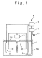
- Fig. 1 shows an ultrasonic test equipment according to a first embodiment of the present invention.
- the ultrasonic test equipment according to the present embodiment includes: a water tank for ultrasonic test, 1 that stores ultrasonic medium 50 as liquid; an ultrasonic probe 2 provided in the water tank for ultrasonic test, 1; an information processing device 3; a temperature control device 4; a test object temperature sensor 5; and an ultrasonic medium temperature sensor 6 provided in the water tank for ultrasonic test, 1.
- the ultrasonic medium 50 is, for example, water.
- Each of the test object temperature sensor 5 and the ultrasonic medium temperature sensor 6 is a thermocouple as a contact-type temperature sensor.
- the temperature control device 4 includes a temperature comparing device 7, a heating device 8 provided in the water tank for ultrasonic test, 1, and a control device 9.
- the heating device 8 is an electric heater or a heat pump for heating the ultrasonic medium 50 by using electric power.
- the test object temperature sensor 5 measures an test object temperature as a surface temperature of the test object 60 and the ultrasonic medium temperature sensor 6 measures a medium temperature as a temperature of the ultrasonic medium 50.
- the temperature comparing device 7 detects a high-low relation between the test object temperature and the medium temperature based on a direction of an electromotive force caused by the test object temperature sensor 5 and the ultrasonic medium temperature sensor 6.
- the control device 9 controls the heating device 8 based on the high-low relation between the test object temperature and the medium temperature such that the medium temperature becomes equal to or higher than the test object temperature.
- the heating device 8 heats the ultrasonic medium 50 such that the medium temperature becomes equal to or higher than the test object temperature.
- the test object 60 After the medium temperature becomes equal to or higher than the test object temperature, the test object 60 is immersed in the ultrasonic medium 50.
- the ultrasonic test equipment Under the condition that the test object 60 is being immersed in the ultrasonic medium 50, the ultrasonic test equipment according to the present embodiment performs an ultrasonic test of the test object 60. More specifically, the ultrasonic probe 2 outputs ultrasonic waves towards the test object 60 and converts ultrasonic waves from the test object 60 into electric signals. The information processing device 3 outputs a result of the ultrasonic test based on the electric signals.
- the temperature of the ultrasonic medium 50 is equal to or higher than the surface temperature of the test obj ect 60. Therefore, the ultrasonic medium 50 in the vicinity of the test object 60 is cooled by the test obj ect 60 such that the temperature of the ultrasonic medium 50 is lowered and a saturation concentration of dissolved gas is increased therein. As a result, gas bubbles are prevented from emerging on a surface of the test object 60. The effect of preventing gas bubbles from emerging on the surface of the test obj ect 60 is maintained during the ultrasonic test.
- the water tank for ultrasonic test, 1 is provided with a heat insulating member 10A.
- the heat insulating member 10A reduces energy for heating the ultrasonic medium 50.
- a floating member 11A is floated on the ultrasonic medium 50.
- the floating member 11A suppresses evaporation at a liquid surface of the ultrasonic medium 50. Since heat dissipation from the ultrasonic medium 50 due to heat of evaporation is suppressed, energy for heating the ultrasonic medium 50 is reduced.
- expanded polystyrene it is preferred to use expanded polystyrene as the floating member 11A.
- the expanded polystyrene has a heat insulating property and does not scratch the test object 60.
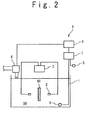
- Fig. 2 shows an ultrasonic test equipment according to a second embodiment of the present invention.
- the ultrasonic test equipment according to the present embodiment includes: a water tank for ultrasonic test, 1 that stores ultrasonic medium 50 as liquid; an ultrasonic probe 2 provided in the water tank for ultrasonic test, 1; an information processing device 3; a temperature control device 4; a test object temperature sensor 5; and an ultrasonic medium temperature sensor 6 provided in the water tank for ultrasonic test, 1.
- the temperature control device 4 includes a temperature comparing device 7, a heating device 8 and a control device 9.
- the heating device 8 is a solar water heater that is provided outside the water tank for ultrasonic test, 1.
- the ultrasonic medium 50 circulates between the water tank for ultrasonic test, 1 and the heating device 8. Alternatively, the ultrasonic medium 50 flows through the heating device 8 and then flows into the water tank for ultrasonic test, 1, and the ultrasonic medium 50 that flows out of the water tank for ultrasonic test, 1 does not return to the heating device 8.
- the heating device 8 heats the ultrasonic medium 50 by using solar heat. Since solar heat is used, emission of carbon dioxide is reduced.
- the ultrasonic test equipment and an ultrasonic test method according to the present embodiment are the same as the ultrasonic test equipment and the ultrasonic test method according to the first embodiment except the points described above.
- each of the test object temperature sensor 5 and the ultrasonic medium temperature sensor 6 may be a mercury thermometer, an alcohol thermometer or a thermistor as a contact-type temperature sensor.
- the temperature comparing device 7 displays the test object temperature and the medium temperature such that those can be compared.
- An operator manually operates the control device 9 based on a high-low relation between the test obj ect temperature and the medium temperature to cause the heating device 8 to heat the ultrasonic medium 50 such that the medium temperature becomes equal to or higher than the test obj ect temperature.
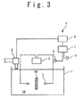
- Fig. 3 shows an ultrasonic test equipment according to a third embodiment.
- the ultrasonic test equipment according to the present embodiment includes: a water tank for ultrasonic test, 1 that stores ultrasonic medium 50 as liquid; an ultrasonic probe 2 provided in the water tank for ultrasonic test, 1; an information processing device 3; a temperature control device 4; a test object temperature sensor 5; and an ultrasonic medium temperature sensor 6.
- the temperature control device 4 includes a temperature comparing device 7, a heating device 8 and a control device 9.
- the heating device 8 is a reactor provided outside the water tank for ultrasonic test, 1.
- the ultrasonic medium 50 circulates between the water tank for ultrasonic test, 1 and the heating device 8.
- the ultrasonic medium 50 flows through the heating device 8 and then flows into the water tank for ultrasonic test, 1, and the ultrasonic medium 50 that flows out of the water tank for ultrasonic test, 1 does not return to the heating device 8.
- a chemical reaction occurs in the heating device 8 and the heating device 8 heats the ultrasonic medium 50 by supplying heat generated by the chemical reaction.
- the chemical reaction there is acombustion reaction of gas fuel or liquid fuel; or a reaction caused by adding water to limewater or quick lime.
- Each of the test obj ect temperature sensor 5 and the ultrasonic medium temperature sensor 6 is a radiation temperature sensor or a thermo graphy as a noncontact-type temperature sensor.
- the test object temperature sensor 5 measures a test object temperature as a surface temperature of the test object 60.
- the ultrasonic medium temperature sensor 6 measures a medium temperature as a surface temperature of the ultrasonic medium 50 stored in the water tank for ultrasonic test, 1.
- the ultrasonic test equipment and an ultrasonic test method according to the present embodiment are the same as the ultrasonic test equipment and the ultrasonic test method according to the first embodiment except the points described above.
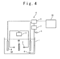
- Fig. 4 shows an ultrasonic test equipment according to a fourth embodiment of the present invention.
- the ultrasonic test equipment according to the present embodiment includes: a water tank for ultrasonic test, 1 that stores ultrasonic medium 50 as liquid; an ultrasonic probe 2 provided in the water tank for ultrasonic test, 1; an information processing device 3; a temperature control device 4; a test object temperature sensor 5; and an ultrasonic medium temperature sensor 6 provided in the water tank for ultrasonic test, 1.
- the ultrasonic medium 50 is, for example, water.
- Each of the test object temperature sensor 5 and the ultrasonic medium temperature sensor 6 is a thermocouple as a contact-type temperature sensor.
- the temperature control device 4 includes a temperature comparing device 7, a heating device 8 provided in the water tank for ultrasonic test, 1, the control device 9 and a cooling device 20.
- the heating device 8 is an electric heater or a heat pump for heating the ultrasonic medium 50 by using electric power.
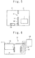
- Fig. 5 is a plan view showing an arrangement of the water tank for ultrasonic test, 1 and the cooling device 20.
- the water tank for ultrasonic test, 1 is arranged in a test room 31.
- the cooling device 20 includes a refrigerator 22A and functions as a room cooler.
- a carrying-in entrance 34 is formed in a wall 33 between the test room 31 and a pre-room 32.
- a door, which is not shown in the figure, is provided at the carrying-in entrance 34.
- the pre-room 32 is, for example, adjacent to the test room 31.
- the cooling device 20 is provided, for example, in the pre-room 31.
- the test object 60 is carried into the pre-room 32.
- the test obj ect temperature sensor 5 measures a test obj ect temperature as a surface temperature of the test object 60 and the ultrasonic medium temperature sensor 6 measures a medium temperature as a temperature of the ultrasonic medium 50.
- the temperature comparing device 7 detects a high-low relation between the test object temperature and the medium temperature based on a direction of an electromotive force caused by the test object temperature sensor 5 and the ultrasonic medium temperature sensor 6.
- the control device 9 controls the heating device 8, the cooling device 20 or both of the heating device 8 and the cooling device 20 based on the high-low relation between the test object temperature and the medium temperature such that the medium temperature becomes equal to or higher than the test object temperature.
- the heating device 8 heats the ultrasonic medium 50 based on the control by the control device 9 such that the medium temperature becomes equal to or higher than the test obj ect temperature.
- the refrigerator 22A cools air in the pre-room 32 based on the control by the control device 9 such that the medium temperature becomes equal to or higher than the test object temperature.
- the air in the pre-room 32 functions as heat transfer medium that deprives the test object 60 of heat.
- the test object 60 is carried from the pre-room 32 into the test room 31 through the carrying-in entrance 34, and then the test object 60 is immersed in the ultrasonic medium 50.
- the ultrasonic test equipment Under the condition that the test object 60 is being immersed in the ultrasonic medium 50, the ultrasonic test equipment according to the present embodiment performs an ultrasonic test of the test object 60 as same in the first embodiment.
- the temperature of the ultrasonic medium 50 is equal to or higher than the surface temperature of the test obj ect 60. Therefore, the ultrasonic medium 50 in the vicinity of the test object 60 is cooled by the test object 60 such that the temperature of the ultrasonic medium 50 is lowered and a saturation concentration of dissolved gas is increased therein. As a result, gas bubbles are prevented from emerging on a surface of the test object 60. The effect of preventing gas bubbles from emerging on the surface of the test object 60 is maintained during the ultrasonic test.
- an air temperature sensor provided in the pre-room 32 can be used as the test object temperature sensor 5 when the test obj ect 60 in the pre-room 32 and the air in the pre-room 32 are in thermal equilibrium.
- each of the test object temperature sensor 5 and the ultrasonic medium temperature sensor 6 may be a mercury thermometer, an alcohol thermometer or a thermistor as a contact-type temperature sensor.
- the ultrasonic test method is same as that exemplified in the second embodiment.
- a room temperature of the pre-room 32 is kept lower than a room temperature of the test room 31.
- the wall 33 is provided with a heat insulating member 10B.
- the heat insulating member 10B prevents heat from penetrating from the test room 31 to the pre-room 32 and thus reduces energy for cooling the air in the pre-room 32.
- Fig. 6 shows a cooling device 20 of an ultrasonic test equipment according to a fifth embodiment of the present invention.
- the cooling device 20 includes a cooling water tank 21 for storing cooling water 70 as heat transfer medium that deprives the test object 60 of heat and a refrigerator 22B for cooling the cooling water 70.
- the ultrasonic test equipment according to the present embodiment is the same as the ultrasonic test equipment according to the fourth embodiment except the points described above.
- the test object 60 is immersed in the cooling water 70.
- the test object temperature sensor 5 measures a test object temperature as a surface temperature of the test object 60 and the ultrasonic medium temperature sensor 6 measures a medium temperature as a temperature of the ultrasonic medium 50.
- the temperature comparing device 7 detects a high-low relation between the test object temperature and the medium temperature based on a direction of an electromotive force caused by the test object temperature sensor 5 and the ultrasonic medium temperature sensor 6.
- the control device 9 controls the heating device 8, the cooling device 20 or both of the heating device 8 and the cooling device 20 based on the high-low relation between the test object temperature and the medium temperature such that the medium temperature becomes equal to or higher than the test obj ect temperature.
- the heating device 8 heats the ultrasonic medium 50 based on the control by the control device 9 such that the medium temperature becomes equal to or higher than the test object temperature.
- the refrigerator 22B cools the cooling water 70 based on the control by the control device 9 such that the medium temperature becomes equal to or higher than the test object temperature.
- the test object 60 is taken out from the cooling water 70 and is immersed in the ultrasonic medium 50.
- the ultrasonic test equipment Under the condition that the test object 60 is being immersed in the ultrasonic medium 50, the ultrasonic test equipment according to the present embodiment performs an ultrasonic test of the test object 60 as same in the first embodiment.
- gas bubbles are prevented from emerging on a surface of the test object 60 as same in the fourth embodiment.
- the cooling water tank 21 is provided with a heat insulating member 10C.
- the heat insulating member 10C reduces energy for cooling the cooling water 70.
- a floating member 11B is floated on the cooling water 70.
- the floating member 11B suppresses heat transfer through a liquid surface of the cooling water 70. Therefore, energy for cooling the cooling water 70 is reduced. It is preferred to use expanded polystyrene as the floating member 11B.
- Fig. 7 shows a cooling device 20 of an ultrasonic test equipment according to a sixth embodiment of the present invention.
- the cooling device 20 includes a refrigerator 22C for cooling cooling water 70 as heat transfer medium that deprives the test object 60 of heat and a shower 23 for pouring the cooling water 70 on the test object 60.
- the ultrasonic test equipment according to the present embodiment is the same as the ultrasonic test equipment according to the fourth embodiment except the points described above.
- the shower 23 pours the cooling water 70 on the test object 60.
- the test object temperature sensor 5 measures a test object temperature as a surface temperature of the test object 60 and the ultrasonic medium temperature sensor 6 measures a medium temperature as a temperature of the ultrasonic medium 50.
- the temperature comparing device 7 detects a high-low relation between the test object temperature and the medium temperature based on a direction of an electromotive force caused by the test object temperature sensor 5 and the ultrasonic medium temperature sensor 6.
- the control device 9 controls the heating device 8, the cooling device 20 or both of the heating device 8 and the cooling device 20 based on the high-low relation between the test object temperature and the medium temperature such that the medium temperature becomes equal to or higher than the test obj ect temperature.
- the heating device 8 heats the ultrasonic medium 50 based on the control by the control device 9 such that the medium temperature becomes equal to or higher than the test object temperature.
- the refrigerator 22B cools the cooling water 70 based on the control by the control device 9 such that the medium temperature becomes equal to or higher than the test object temperature.
- the test object 60 After the medium temperature becomes equal to or higher than the test object temperature, the test object 60 is immersed in the ultrasonic medium 50.
- the ultrasonic test equipment Under the condition that the test object 60 is being immersed in the ultrasonic medium 50, the ultrasonic test equipment according to the present embodiment performs an ultrasonic test of the test object 60 as in the first embodiment.
- gas bubbles are prevented from emerging on a surface of the test object 60 as same in the fourth embodiment.
- the heating device 8 may not be provided.
- the water tank for ultrasonic test, 1 is provided with the heat insulating member 10A and that the floating member 11A is floated on the ultrasonic medium 50.
Landscapes
- Physics & Mathematics (AREA)
- Health & Medical Sciences (AREA)
- Life Sciences & Earth Sciences (AREA)
- Chemical & Material Sciences (AREA)
- Analytical Chemistry (AREA)
- Biochemistry (AREA)
- General Health & Medical Sciences (AREA)
- General Physics & Mathematics (AREA)
- Immunology (AREA)
- Pathology (AREA)
- Acoustics & Sound (AREA)
- Investigating Or Analyzing Materials By The Use Of Ultrasonic Waves (AREA)
Abstract
An ultrasonic test equipment includes a water tank for storing ultrasonic medium, an ultrasonic probe provided in the water tank, an ultrasonic medium temperature sensor configured to measure a first temperature of the ultrasonic medium, a test object temperature sensor configured to measure a second temperature of a test object, and a temperature control device. The temperature control device heats the ultrasonic medium or cools the test object such that the first temperature becomes equal to or higher than the second temperature. Gas bubbles are prevented from emerging on a surface of the test object.
Description
- The present invention relates to an ultrasonic test equipment and an ultrasonic test method, and in particular relates to a water immerse type ultrasonic test equipment and a water immerse type ultrasonic test method.
- There is a problem that gas bubbles adhered to a surface of a probe of a water immerse type ultrasonic test equipment or a surface of a test object may disturb a flaw detection.
- To cope with this problem, Japanese Patent Publication (
JP-A-Heisei 11-211702 - Apart from the problem of gas bubbles as mentioned above, Japanese Patent Publication (
JP-A-Heisei 6-66545 -
- Patent literature 1: Japanese Patent Publication (
JP-A-Heisei 11-211702 - Patent literature 2: Japanese Patent Publication (
JP-A-Heisei 6-66545 - An object of the present invention is to provide an ultrasonic test equipment and an ultrasonic test method capable of preventing gas bubbles from emerging on a surface of an test object.
- In a first aspect of the present invention, an ultrasonic test equipment includes: a water tank for storing ultrasonic medium; an ultrasonic probe provided in the water tank; an ultrasonic medium temperature sensor configured to measure a first temperature of the ultrasonic medium; a test object temperature sensor configured to measure a second temperature of an test object; and a temperature control device. The temperature control device heats the ultrasonic medium or cools the test object such that the first temperature becomes equal to or higher than the second temperature.
- It is preferred that the temperature control device includes a refrigerator configured to cool heat transfer medium for depriving the test object of heat.
- It is preferred that the test object is carried from a pre-room into a test room in which the water tank is arranged. In this case, the heat transfer medium is air in the pre-room.
- It is preferred that the temperature control device includes a cooling water tank for storing cooling water as the heat transfer medium.
- It is preferred that the temperature control device includes a shower configured to pour cooling water as the heat transfer medium on the test object.
- It is preferred that the temperature control device includes an electric heater or a heat pump for heating the ultrasonic medium.
- It is preferred that the temperature control device includes a solar water heater configured to heat the ultrasonic medium.
- It is preferred that the temperature control device includes a reactor in which a chemical reaction occurs. The reactor supplies the ultrasonic medium with heat generated by the chemical reaction.
- In a second aspect of the present invention, an ultrasonic test method includes: measuring a first temperature of ultrasonic medium stored in a water tank; measuring a second temperature of an test object; heating the ultrasonic medium or cooling the test object such that the first temperature becomes equal to or higher than the second temperature; immersing the test object in the ultrasonic medium; and performing an ultrasonic test of the test object.
- It is preferred that the ultrasonic test method further includes cooling heat transfer medium for depriving the test object of heat.
- It is preferred that the heat transfer medium is air in a pre-room. It is preferred that the ultrasonic test method further includes carrying the test object from the pre-room into a test room in which the water tank is arranged.
- It is preferred that the heat transfer medium is cooling water stored in a cooling water tank. It is preferred that the heating of the ultrasonic medium or the cooling of the test object includes immersing the test object in the cooling water.
- It is preferred that the heat transfer medium is cooling water. It is preferred that the heating of the ultrasonic medium or the cooling of the test object includes pouring the cooling water on the test object.
- It is preferred that the heating of the ultrasonic medium or the cooling of the test object includes heating the ultrasonic medium.
- It is preferred that the ultrasonic medium is heated by using solar heat in the heating the ultrasonic medium.
- It is preferred that the ultrasonic medium is supplied with heat generated by a chemical reaction in the heating the ultrasonic medium.
- According to the present invention, an ultrasonic test equipment and an ultrasonic test method capable of preventing gas bubbles from emerging on a surface of an test object are provided.
- The above and other objects, advantages, and features of the present invention will be more apparent from the description of embodiments taken in conjunction with the accompanying drawings, in which:
-
Fig. 1 is a schematic diagram of an ultrasonic test equipment according to a first embodiment of the present invention; -
Fig. 2 is a schematic diagram of an ultrasonic test equipment according to a second embodiment of the present invention; -
Fig. 3 is a schematic diagram of an ultrasonic test equipment according to a third embodiment of the present invention; -
Fig. 4 is a schematic diagram of an ultrasonic test equipment according to a fourth embodiment of the present invention; -
Fig. 5 is a plan view showing an arrangement of a water tank for ultrasonic test and a cooling device of the ultrasonic test equipment according to the fourth embodiment; -
Fig. 6 is a schematic diagram of a cooling device of an ultrasonic test equipment according to a fifth embodiment of the present invention; and -
Fig. 7 is a schematic diagram of a cooling device of an ultrasonic test equipment according to a sixth embodiment of the present invention. - With reference to the accompanying drawings, embodiments of an ultrasonic test equipment and an ultrasonic test method according to the present invention will be described below.
-
Fig. 1 shows an ultrasonic test equipment according to a first embodiment of the present invention. The ultrasonic test equipment according to the present embodiment includes: a water tank for ultrasonic test, 1 that storesultrasonic medium 50 as liquid; anultrasonic probe 2 provided in the water tank for ultrasonic test, 1; aninformation processing device 3; a temperature control device 4; a testobject temperature sensor 5; and an ultrasonicmedium temperature sensor 6 provided in the water tank for ultrasonic test, 1. Theultrasonic medium 50 is, for example, water. Each of the testobject temperature sensor 5 and the ultrasonicmedium temperature sensor 6 is a thermocouple as a contact-type temperature sensor. The temperature control device 4 includes atemperature comparing device 7, aheating device 8 provided in the water tank for ultrasonic test, 1, and acontrol device 9. Theheating device 8 is an electric heater or a heat pump for heating theultrasonic medium 50 by using electric power. - An ultrasonic test method according to the present embodiment is described below.
- Before a
test object 60 is immersed in theultrasonic medium 50, the testobject temperature sensor 5 measures an test object temperature as a surface temperature of thetest object 60 and the ultrasonicmedium temperature sensor 6 measures a medium temperature as a temperature of theultrasonic medium 50. Thetemperature comparing device 7 detects a high-low relation between the test object temperature and the medium temperature based on a direction of an electromotive force caused by the testobject temperature sensor 5 and the ultrasonicmedium temperature sensor 6. Thecontrol device 9 controls theheating device 8 based on the high-low relation between the test object temperature and the medium temperature such that the medium temperature becomes equal to or higher than the test object temperature. Theheating device 8 heats the ultrasonic medium 50 such that the medium temperature becomes equal to or higher than the test object temperature. - After the medium temperature becomes equal to or higher than the test object temperature, the
test object 60 is immersed in theultrasonic medium 50. - Under the condition that the
test object 60 is being immersed in theultrasonic medium 50, the ultrasonic test equipment according to the present embodiment performs an ultrasonic test of thetest object 60. More specifically, theultrasonic probe 2 outputs ultrasonic waves towards thetest object 60 and converts ultrasonic waves from thetest object 60 into electric signals. Theinformation processing device 3 outputs a result of the ultrasonic test based on the electric signals. - In the present embodiment, when the
test object 60 is immersed in theultrasonic medium 50, the temperature of theultrasonic medium 50 is equal to or higher than the surface temperature of thetest obj ect 60. Therefore, the ultrasonic medium 50 in the vicinity of thetest object 60 is cooled by thetest obj ect 60 such that the temperature of theultrasonic medium 50 is lowered and a saturation concentration of dissolved gas is increased therein. As a result, gas bubbles are prevented from emerging on a surface of thetest object 60. The effect of preventing gas bubbles from emerging on the surface of thetest obj ect 60 is maintained during the ultrasonic test. - In the present embodiment, it is preferred that the water tank for ultrasonic test, 1 is provided with a
heat insulating member 10A. Theheat insulating member 10A reduces energy for heating theultrasonic medium 50. - Moreover, it is preferred that a floating
member 11A is floated on theultrasonic medium 50. The floatingmember 11A suppresses evaporation at a liquid surface of theultrasonic medium 50. Since heat dissipation from theultrasonic medium 50 due to heat of evaporation is suppressed, energy for heating theultrasonic medium 50 is reduced. It is preferred to use expanded polystyrene as the floatingmember 11A. The expanded polystyrene has a heat insulating property and does not scratch thetest object 60. -
Fig. 2 shows an ultrasonic test equipment according to a second embodiment of the present invention. The ultrasonic test equipment according to the present embodiment includes: a water tank for ultrasonic test, 1 that stores ultrasonic medium 50 as liquid; anultrasonic probe 2 provided in the water tank for ultrasonic test, 1; aninformation processing device 3; a temperature control device 4; a testobject temperature sensor 5; and an ultrasonicmedium temperature sensor 6 provided in the water tank for ultrasonic test, 1. The temperature control device 4 includes atemperature comparing device 7, aheating device 8 and acontrol device 9. In the present embodiment, theheating device 8 is a solar water heater that is provided outside the water tank for ultrasonic test, 1. Theultrasonic medium 50 circulates between the water tank for ultrasonic test, 1 and theheating device 8. Alternatively, the ultrasonic medium 50 flows through theheating device 8 and then flows into the water tank for ultrasonic test, 1, and the ultrasonic medium 50 that flows out of the water tank for ultrasonic test, 1 does not return to theheating device 8. Theheating device 8 heats theultrasonic medium 50 by using solar heat. Since solar heat is used, emission of carbon dioxide is reduced. - The ultrasonic test equipment and an ultrasonic test method according to the present embodiment are the same as the ultrasonic test equipment and the ultrasonic test method according to the first embodiment except the points described above.
- In the present embodiment, each of the test
object temperature sensor 5 and the ultrasonicmedium temperature sensor 6 may be a mercury thermometer, an alcohol thermometer or a thermistor as a contact-type temperature sensor. In this case, thetemperature comparing device 7 displays the test object temperature and the medium temperature such that those can be compared. An operator manually operates thecontrol device 9 based on a high-low relation between the test obj ect temperature and the medium temperature to cause theheating device 8 to heat the ultrasonic medium 50 such that the medium temperature becomes equal to or higher than the test obj ect temperature. -
Fig. 3 shows an ultrasonic test equipment according to a third embodiment. The ultrasonic test equipment according to the present embodiment includes: a water tank for ultrasonic test, 1 that stores ultrasonic medium 50 as liquid; anultrasonic probe 2 provided in the water tank for ultrasonic test, 1; aninformation processing device 3; a temperature control device 4; a testobject temperature sensor 5; and an ultrasonicmedium temperature sensor 6. The temperature control device 4 includes atemperature comparing device 7, aheating device 8 and acontrol device 9. In the present embodiment, theheating device 8 is a reactor provided outside the water tank for ultrasonic test, 1. Theultrasonic medium 50 circulates between the water tank for ultrasonic test, 1 and theheating device 8. Alternatively, the ultrasonic medium 50 flows through theheating device 8 and then flows into the water tank for ultrasonic test, 1, and the ultrasonic medium 50 that flows out of the water tank for ultrasonic test, 1 does not return to theheating device 8. A chemical reaction occurs in theheating device 8 and theheating device 8 heats theultrasonic medium 50 by supplying heat generated by the chemical reaction. As the chemical reaction, there is acombustion reaction of gas fuel or liquid fuel; or a reaction caused by adding water to limewater or quick lime. Each of the test object temperature sensor 5 and the ultrasonicmedium temperature sensor 6 is a radiation temperature sensor or a thermo graphy as a noncontact-type temperature sensor. The testobject temperature sensor 5 measures a test object temperature as a surface temperature of thetest object 60. The ultrasonicmedium temperature sensor 6 measures a medium temperature as a surface temperature of the ultrasonic medium 50 stored in the water tank for ultrasonic test, 1. - The ultrasonic test equipment and an ultrasonic test method according to the present embodiment are the same as the ultrasonic test equipment and the ultrasonic test method according to the first embodiment except the points described above.
-
Fig. 4 shows an ultrasonic test equipment according to a fourth embodiment of the present invention. The ultrasonic test equipment according to the present embodiment includes: a water tank for ultrasonic test, 1 that stores ultrasonic medium 50 as liquid; anultrasonic probe 2 provided in the water tank for ultrasonic test, 1; aninformation processing device 3; a temperature control device 4; a testobject temperature sensor 5; and an ultrasonicmedium temperature sensor 6 provided in the water tank for ultrasonic test, 1. Theultrasonic medium 50 is, for example, water. Each of the testobject temperature sensor 5 and the ultrasonicmedium temperature sensor 6 is a thermocouple as a contact-type temperature sensor. The temperature control device 4 includes atemperature comparing device 7, aheating device 8 provided in the water tank for ultrasonic test, 1, thecontrol device 9 and acooling device 20. Theheating device 8 is an electric heater or a heat pump for heating theultrasonic medium 50 by using electric power. -
Fig. 5 is a plan view showing an arrangement of the water tank for ultrasonic test, 1 and thecooling device 20. The water tank for ultrasonic test, 1 is arranged in atest room 31. Thecooling device 20 includes arefrigerator 22A and functions as a room cooler. A carrying-inentrance 34 is formed in awall 33 between thetest room 31 and a pre-room 32. A door, which is not shown in the figure, is provided at the carrying-inentrance 34. The pre-room 32 is, for example, adjacent to thetest room 31. Thecooling device 20 is provided, for example, in thepre-room 31. - An ultrasonic test method according to the present embodiment is described below.
- The
test object 60 is carried into the pre-room 32. The test object temperature sensor 5 measures a test obj ect temperature as a surface temperature of thetest object 60 and the ultrasonicmedium temperature sensor 6 measures a medium temperature as a temperature of theultrasonic medium 50. Thetemperature comparing device 7 detects a high-low relation between the test object temperature and the medium temperature based on a direction of an electromotive force caused by the testobject temperature sensor 5 and the ultrasonicmedium temperature sensor 6. Thecontrol device 9 controls theheating device 8, thecooling device 20 or both of theheating device 8 and thecooling device 20 based on the high-low relation between the test object temperature and the medium temperature such that the medium temperature becomes equal to or higher than the test object temperature. Theheating device 8 heats the ultrasonic medium 50 based on the control by thecontrol device 9 such that the medium temperature becomes equal to or higher than the test obj ect temperature. Therefrigerator 22A cools air in the pre-room 32 based on the control by thecontrol device 9 such that the medium temperature becomes equal to or higher than the test object temperature. The air in the pre-room 32 functions as heat transfer medium that deprives thetest object 60 of heat. - After the medium temperature becomes equal to or higher than the test object temperature, the
test object 60 is carried from the pre-room 32 into thetest room 31 through the carrying-inentrance 34, and then thetest object 60 is immersed in theultrasonic medium 50. - Under the condition that the
test object 60 is being immersed in theultrasonic medium 50, the ultrasonic test equipment according to the present embodiment performs an ultrasonic test of thetest object 60 as same in the first embodiment. - In the present embodiment, when the
test object 60 is immersed in theultrasonic medium 50, the temperature of theultrasonic medium 50 is equal to or higher than the surface temperature of thetest obj ect 60. Therefore, the ultrasonic medium 50 in the vicinity of thetest object 60 is cooled by thetest object 60 such that the temperature of theultrasonic medium 50 is lowered and a saturation concentration of dissolved gas is increased therein. As a result, gas bubbles are prevented from emerging on a surface of thetest object 60. The effect of preventing gas bubbles from emerging on the surface of thetest object 60 is maintained during the ultrasonic test. - It is noted that an air temperature sensor provided in the pre-room 32 can be used as the test
object temperature sensor 5 when thetest obj ect 60 in the pre-room 32 and the air in the pre-room 32 are in thermal equilibrium. In this case, in order to avoid influences of a tolerance and an instrumental error, it is preferred to control the medium temperature, the test object temperature or both of them such that there arises a finite temperature difference (for example, 2 °C) between the medium temperature and the test object temperature. - In the present embodiment, each of the test
object temperature sensor 5 and the ultrasonicmedium temperature sensor 6 may be a mercury thermometer, an alcohol thermometer or a thermistor as a contact-type temperature sensor. In this case, the ultrasonic test method is same as that exemplified in the second embodiment. - In the present embodiment, it is preferred that a room temperature of the pre-room 32 is kept lower than a room temperature of the
test room 31. - In the present embodiment, it is preferred that the
wall 33 is provided with aheat insulating member 10B. Theheat insulating member 10B prevents heat from penetrating from thetest room 31 to the pre-room 32 and thus reduces energy for cooling the air in thepre-room 32. -
Fig. 6 shows acooling device 20 of an ultrasonic test equipment according to a fifth embodiment of the present invention. Thecooling device 20 includes a coolingwater tank 21 for storing coolingwater 70 as heat transfer medium that deprives thetest object 60 of heat and arefrigerator 22B for cooling the coolingwater 70. - The ultrasonic test equipment according to the present embodiment is the same as the ultrasonic test equipment according to the fourth embodiment except the points described above.
- An ultrasonic test method according to the present embodiment is described below.
- The
test object 60 is immersed in the coolingwater 70. The testobject temperature sensor 5 measures a test object temperature as a surface temperature of thetest object 60 and the ultrasonicmedium temperature sensor 6 measures a medium temperature as a temperature of theultrasonic medium 50. Thetemperature comparing device 7 detects a high-low relation between the test object temperature and the medium temperature based on a direction of an electromotive force caused by the testobject temperature sensor 5 and the ultrasonicmedium temperature sensor 6. Thecontrol device 9 controls theheating device 8, thecooling device 20 or both of theheating device 8 and thecooling device 20 based on the high-low relation between the test object temperature and the medium temperature such that the medium temperature becomes equal to or higher than the test obj ect temperature. Theheating device 8 heats the ultrasonic medium 50 based on the control by thecontrol device 9 such that the medium temperature becomes equal to or higher than the test object temperature. Therefrigerator 22B cools the coolingwater 70 based on the control by thecontrol device 9 such that the medium temperature becomes equal to or higher than the test object temperature. - After the medium temperature becomes equal to or higher than the test object temperature, the
test object 60 is taken out from the coolingwater 70 and is immersed in theultrasonic medium 50. - Under the condition that the
test object 60 is being immersed in theultrasonic medium 50, the ultrasonic test equipment according to the present embodiment performs an ultrasonic test of thetest object 60 as same in the first embodiment. - Also, in the present embodiment, gas bubbles are prevented from emerging on a surface of the
test object 60 as same in the fourth embodiment. - In the present embodiment, it is preferred that the cooling
water tank 21 is provided with a heat insulating member 10C. The heat insulating member 10C reduces energy for cooling the coolingwater 70. - It is also preferred that a floating
member 11B is floated on the coolingwater 70. The floatingmember 11B suppresses heat transfer through a liquid surface of the coolingwater 70. Therefore, energy for cooling the coolingwater 70 is reduced. It is preferred to use expanded polystyrene as the floatingmember 11B. -
Fig. 7 shows acooling device 20 of an ultrasonic test equipment according to a sixth embodiment of the present invention. Thecooling device 20 includes a refrigerator 22C for cooling coolingwater 70 as heat transfer medium that deprives thetest object 60 of heat and ashower 23 for pouring the coolingwater 70 on thetest object 60. - The ultrasonic test equipment according to the present embodiment is the same as the ultrasonic test equipment according to the fourth embodiment except the points described above.
- An ultrasonic test method according to the present embodiment is described below.
- The
shower 23 pours the coolingwater 70 on thetest object 60. The testobject temperature sensor 5 measures a test object temperature as a surface temperature of thetest object 60 and the ultrasonicmedium temperature sensor 6 measures a medium temperature as a temperature of theultrasonic medium 50. Thetemperature comparing device 7 detects a high-low relation between the test object temperature and the medium temperature based on a direction of an electromotive force caused by the testobject temperature sensor 5 and the ultrasonicmedium temperature sensor 6. Thecontrol device 9 controls theheating device 8, thecooling device 20 or both of theheating device 8 and thecooling device 20 based on the high-low relation between the test object temperature and the medium temperature such that the medium temperature becomes equal to or higher than the test obj ect temperature. Theheating device 8 heats the ultrasonic medium 50 based on the control by thecontrol device 9 such that the medium temperature becomes equal to or higher than the test object temperature. Therefrigerator 22B cools the coolingwater 70 based on the control by thecontrol device 9 such that the medium temperature becomes equal to or higher than the test object temperature. - After the medium temperature becomes equal to or higher than the test object temperature, the
test object 60 is immersed in theultrasonic medium 50. - Under the condition that the
test object 60 is being immersed in theultrasonic medium 50, the ultrasonic test equipment according to the present embodiment performs an ultrasonic test of thetest object 60 as in the first embodiment. - Also, in the present embodiment, gas bubbles are prevented from emerging on a surface of the
test object 60 as same in the fourth embodiment. - In the fourth to sixth embodiments, the
heating device 8 may not be provided. - Also, in the second to sixth embodiments, it is preferred that the water tank for ultrasonic test, 1 is provided with the
heat insulating member 10A and that the floatingmember 11A is floated on theultrasonic medium 50. - It is noted that the above embodiments can be combined.
- The present invention has been described with reference to the embodiments; however, the present invention is not limited to the above embodiments. Various modifications can be applied to the above embodiments.
- This application is based upon and claims the benefit of priority from Japanese Patent Application No.
2008-185894, filed on July 17, 2008
Claims (16)
- An ultrasonic test equipment comprising:a water tank for storing ultrasonic medium;an ultrasonic probe provided in said water tank;an ultrasonic medium temperature sensor configured to measure a first temperature of said ultrasonic medium;a test object temperature sensor configured to measure a second temperature of a test object; anda temperature control device,wherein said temperature control device heats said ultrasonic medium or cools said test object such that said first temperature becomes equal to or higher than said second temperature.
- The ultrasonic test equipment according to claim 1, wherein said temperature control device includes a refrigerator configured to cool heat transfer medium for depriving said test object of heat.
- The ultrasonic test equipment according to claim 2, wherein said test object is carried from a pre-room into a test room in which said water tank is arranged, and
said heat transfer medium is air in said pre-room. - The ultrasonic test equipment according to claim 2, wherein said temperature control device includes a cooling water tank for storing cooling water as said heat transfer medium.
- The ultrasonic test equipment according to claim 2, wherein said temperature control device includes a shower configured to pour cooling water as said heat transfer medium on said test object.
- The ultrasonic test equipment according to any of claims 1 to 5, wherein said temperature control device includes an electric heater or a heat pump for heating said ultrasonic medium.
- The ultrasonic test equipment according to any of claims 1 to 5, wherein said temperature control device includes a solar water heater configure to heat said ultrasonic medium.
- The ultrasonic test equipment according to any of claims 1 to 5, wherein said temperature control device includes a reactor in which a chemical reaction occurs, and
said reactor supplies said ultrasonic medium with heat generated by said chemical reaction. - An ultrasonic test method comprising:measuring a first temperature of ultrasonic medium stored in a water tank;measuring a second temperature of a test object;heating said ultrasonic medium or cooling said test object such that said first temperature becomes equal to or higher than said second temperature;immersing said test object in said ultrasonic medium; andperforming an ultrasonic test of said test object.
- The ultrasonic test method according to claim 9, further comprising cooling heat transfer medium for depriving said test object of heat.
- The ultrasonic test method according to claim 10, wherein said heat transfer medium is air in a pre-room, and
the ultrasonic test method further comprising carrying said test object from said pre-room into a test room in which said water tank is arranged. - The ultrasonic test method according to claim 10, wherein said heat transfer medium is cooling water stored in a cooling water tank, and
said heating said ultrasonic medium or said cooling said test object includes immersing said test object in said cooling water. - The ultrasonic test method according to claim 10, wherein said heat transfer medium is cooling water, and
said heating said ultrasonic medium or said cooling said test object includes pouring said cooling water on said test object. - The ultrasonic test method according to any of claims 9 to 13, wherein said heating said ultrasonic medium or said cooling said test object includes heating said ultrasonic medium.
- The ultrasonic test method according to claim 14, wherein in said heating said ultrasonic medium, said ultrasonic medium is heated by using solar heat.
- The ultrasonic test method according to claim 14, wherein in said heating said ultrasonic medium, said ultrasonic medium is supplied with heat generated by a chemical reaction.
Applications Claiming Priority (2)
| Application Number | Priority Date | Filing Date | Title |
|---|---|---|---|
| JP2008185894A JP2010025678A (en) | 2008-07-17 | 2008-07-17 | Ultrasonic flaw detector |
| PCT/JP2009/062971 WO2010008068A1 (en) | 2008-07-17 | 2009-07-17 | Ultrasonic flaw detector |
Publications (1)
| Publication Number | Publication Date |
|---|---|
| EP2306184A1 true EP2306184A1 (en) | 2011-04-06 |
Family
ID=41550468
Family Applications (1)
| Application Number | Title | Priority Date | Filing Date |
|---|---|---|---|
| EP09797992A Withdrawn EP2306184A1 (en) | 2008-07-17 | 2009-07-17 | Ultrasonic flaw detector |
Country Status (4)
| Country | Link |
|---|---|
| US (1) | US20110177603A1 (en) |
| EP (1) | EP2306184A1 (en) |
| JP (1) | JP2010025678A (en) |
| WO (1) | WO2010008068A1 (en) |
Families Citing this family (7)
| Publication number | Priority date | Publication date | Assignee | Title |
|---|---|---|---|---|
| WO2017026483A1 (en) * | 2015-08-10 | 2017-02-16 | 国立大学法人 九州工業大学 | Semiconductor inspection device |
| US9933393B2 (en) | 2015-12-09 | 2018-04-03 | The Boeing Company | Apparatuses, methods, and systems for inspecting a composite end portion of a part |
| CN106932480B (en) * | 2015-12-31 | 2019-10-11 | 中核建中核燃料元件有限公司 | A method of improving fuel rod clad pipe reflectoscope stability |
| CN106770640A (en) * | 2016-11-25 | 2017-05-31 | 淮海工学院 | With the matching used laboratory testing rig of sub-bottom profiler |
| KR102645311B1 (en) * | 2018-08-13 | 2024-03-08 | 삼성디스플레이 주식회사 | Apparatus for measuring sample thickness and method for measuring sample thickness |
| CN109444267A (en) * | 2018-12-21 | 2019-03-08 | 核动力运行研究所 | A kind of hot environment thermostatic ultrasonic pilot system |
| US11918996B2 (en) * | 2019-04-15 | 2024-03-05 | Genecapture, Inc. | Integrated cartridge for sample homogenization and nucleic acid fragmentation |
Family Cites Families (6)
| Publication number | Priority date | Publication date | Assignee | Title |
|---|---|---|---|---|
| JPH11211702A (en) * | 1998-01-27 | 1999-08-06 | Japan Nuclear Cycle Development Inst State Of Projects(Jnc) | Water immersion ultrasonic testing equipment |
| JPH11237376A (en) * | 1998-02-19 | 1999-08-31 | Aisin Takaoka Ltd | Preparation of test sample used in measuring sphered degree of graphite |
| JP3484969B2 (en) * | 1998-02-27 | 2004-01-06 | Jfeスチール株式会社 | Online ultrasonic flaw detector |
| JP2001153849A (en) * | 1999-11-29 | 2001-06-08 | Toshiba Tungaloy Co Ltd | Defective measuring machine for thermoplastic resin molded products |
| JP2001201485A (en) * | 2000-01-18 | 2001-07-27 | Nissan Motor Co Ltd | Ultrasonic measuring device and method |
| JP2008185894A (en) | 2007-01-31 | 2008-08-14 | Seiko Epson Corp | Liquid crystal device manufacturing apparatus and liquid crystal device manufacturing method |
-
2008
- 2008-07-17 JP JP2008185894A patent/JP2010025678A/en active Pending
-
2009
- 2009-07-17 US US13/054,268 patent/US20110177603A1/en not_active Abandoned
- 2009-07-17 EP EP09797992A patent/EP2306184A1/en not_active Withdrawn
- 2009-07-17 WO PCT/JP2009/062971 patent/WO2010008068A1/en not_active Ceased
Non-Patent Citations (1)
| Title |
|---|
| See references of WO2010008068A1 * |
Also Published As
| Publication number | Publication date |
|---|---|
| WO2010008068A1 (en) | 2010-01-21 |
| JP2010025678A (en) | 2010-02-04 |
| US20110177603A1 (en) | 2011-07-21 |
Similar Documents
| Publication | Publication Date | Title |
|---|---|---|
| US20110177603A1 (en) | Ultrasonic test equipment | |
| Falsetti et al. | Pool boiling heat transfer of Novec 649 on sandblasted surfaces | |
| Chiavazzo et al. | A sensor for direct measurement of small convective heat fluxes: Validation and application to micro-structured surfaces | |
| JP4841745B2 (en) | Storage device for probe for measuring temperature of container | |
| CZ285062B6 (en) | Calorimetric measuring apparatus | |
| CN101311685B (en) | Thermal mass flow meter | |
| US20160153841A1 (en) | Systems and methods of determining load temperatures | |
| RU2485463C1 (en) | Device for air thermostatting of calorimetric cell | |
| Fan et al. | Investigation on nondestructive evaluation of pipelines using infrared thermography | |
| US12238896B2 (en) | Vapor-air transition detection for two-phase liquid immersion cooling | |
| KR102659795B1 (en) | Inspection system and inspection method | |
| JP2020148769A (en) | Detection method and detection device of loss of seal in canister, canister, and concrete storage container | |
| US6157009A (en) | Advanced reactive system screening tool | |
| Chinthaparthy | Accelerated performance degradation of single-phase cold plates for direct-to-chip liquid cooled data centers | |
| CN114414644A (en) | System and method for measuring oxygen content in liquid alkali metal | |
| JP2010168640A (en) | Unit and method for controlling cooling solution and temperature-measuring element | |
| RU2756337C1 (en) | Device for temperature and vacuum exposure | |
| Padilla et al. | Impact of pressure profile on contact resistance using PGS in iPEBB cooling | |
| JP4893930B2 (en) | Blackbody furnace | |
| JPH06307910A (en) | Volume measuring equipment | |
| EP3120131B1 (en) | Corrosion sensor for heat exchangers | |
| JP4979635B2 (en) | Airtightness determination device and airtightness determination method | |
| CN102353583B (en) | Temperature control system for superconducting material mechanical property test system | |
| Zvizdic et al. | Realization of the temperature scale in the range from 234.3 K (Hg triple point) to 1084.62 C (Cu freezing point) in Croatia | |
| Baba et al. | Development of a 300 L Calibration Bath for Oceanographic Thermometers |
Legal Events
| Date | Code | Title | Description |
|---|---|---|---|
| PUAI | Public reference made under article 153(3) epc to a published international application that has entered the european phase |
Free format text: ORIGINAL CODE: 0009012 |
|
| 17P | Request for examination filed |
Effective date: 20110117 |
|
| AK | Designated contracting states |
Kind code of ref document: A1 Designated state(s): AT BE BG CH CY CZ DE DK EE ES FI FR GB GR HR HU IE IS IT LI LT LU LV MC MK MT NL NO PL PT RO SE SI SK SM TR |
|
| AX | Request for extension of the european patent |
Extension state: AL BA RS |
|
| DAX | Request for extension of the european patent (deleted) | ||
| STAA | Information on the status of an ep patent application or granted ep patent |
Free format text: STATUS: THE APPLICATION HAS BEEN WITHDRAWN |
|
| 18W | Application withdrawn |
Effective date: 20120904 |