EP2306119A2 - Steuerungssystem für mit Erdwärme betriebenes Heiz- und Kühlsystem - Google Patents
Steuerungssystem für mit Erdwärme betriebenes Heiz- und Kühlsystem Download PDFInfo
- Publication number
- EP2306119A2 EP2306119A2 EP10175693A EP10175693A EP2306119A2 EP 2306119 A2 EP2306119 A2 EP 2306119A2 EP 10175693 A EP10175693 A EP 10175693A EP 10175693 A EP10175693 A EP 10175693A EP 2306119 A2 EP2306119 A2 EP 2306119A2
- Authority
- EP
- European Patent Office
- Prior art keywords
- power conversion
- heat
- ground
- pipes
- geothermal heating
- Prior art date
- Legal status (The legal status is an assumption and is not a legal conclusion. Google has not performed a legal analysis and makes no representation as to the accuracy of the status listed.)
- Withdrawn
Links
- 238000001816 cooling Methods 0.000 title claims abstract description 46
- 238000010438 heat treatment Methods 0.000 title claims abstract description 46
- 238000006243 chemical reaction Methods 0.000 claims abstract description 79
- 238000012546 transfer Methods 0.000 claims abstract description 36
- 238000004891 communication Methods 0.000 claims description 16
- 238000000034 method Methods 0.000 claims description 8
- XLYOFNOQVPJJNP-UHFFFAOYSA-N water Substances O XLYOFNOQVPJJNP-UHFFFAOYSA-N 0.000 claims description 6
- 230000002528 anti-freeze Effects 0.000 claims description 4
- -1 antifreeze Substances 0.000 claims description 4
- 239000008367 deionised water Substances 0.000 claims description 4
- 238000010248 power generation Methods 0.000 description 26
- 239000007788 liquid Substances 0.000 description 7
- 230000005540 biological transmission Effects 0.000 description 4
- 239000000428 dust Substances 0.000 description 3
- 238000012423 maintenance Methods 0.000 description 3
- 239000002245 particle Substances 0.000 description 3
- 238000003491 array Methods 0.000 description 2
- 230000001143 conditioned effect Effects 0.000 description 2
- 230000007613 environmental effect Effects 0.000 description 2
- 238000001914 filtration Methods 0.000 description 2
- 239000000446 fuel Substances 0.000 description 2
- 230000002411 adverse Effects 0.000 description 1
- 239000003990 capacitor Substances 0.000 description 1
- 230000001419 dependent effect Effects 0.000 description 1
- 239000012530 fluid Substances 0.000 description 1
- 238000009434 installation Methods 0.000 description 1
- 238000012986 modification Methods 0.000 description 1
- 230000004048 modification Effects 0.000 description 1
- 230000005855 radiation Effects 0.000 description 1
- 238000012552 review Methods 0.000 description 1
- 239000004065 semiconductor Substances 0.000 description 1
Images

Classifications
-
- F—MECHANICAL ENGINEERING; LIGHTING; HEATING; WEAPONS; BLASTING
- F28—HEAT EXCHANGE IN GENERAL
- F28D—HEAT-EXCHANGE APPARATUS, NOT PROVIDED FOR IN ANOTHER SUBCLASS, IN WHICH THE HEAT-EXCHANGE MEDIA DO NOT COME INTO DIRECT CONTACT
- F28D20/00—Heat storage plants or apparatus in general; Regenerative heat-exchange apparatus not covered by groups F28D17/00 or F28D19/00
- F28D20/0052—Heat storage plants or apparatus in general; Regenerative heat-exchange apparatus not covered by groups F28D17/00 or F28D19/00 using the ground body or aquifers as heat storage medium
-
- F—MECHANICAL ENGINEERING; LIGHTING; HEATING; WEAPONS; BLASTING
- F24—HEATING; RANGES; VENTILATING
- F24T—GEOTHERMAL COLLECTORS; GEOTHERMAL SYSTEMS
- F24T10/00—Geothermal collectors
- F24T10/10—Geothermal collectors with circulation of working fluids through underground channels, the working fluids not coming into direct contact with the ground
-
- H—ELECTRICITY
- H02—GENERATION; CONVERSION OR DISTRIBUTION OF ELECTRIC POWER
- H02S—GENERATION OF ELECTRIC POWER BY CONVERSION OF INFRARED RADIATION, VISIBLE LIGHT OR ULTRAVIOLET LIGHT, e.g. USING PHOTOVOLTAIC [PV] MODULES
- H02S40/00—Components or accessories in combination with PV modules, not provided for in groups H02S10/00 - H02S30/00
- H02S40/40—Thermal components
- H02S40/44—Means to utilise heat energy, e.g. hybrid systems producing warm water and electricity at the same time
-
- H—ELECTRICITY
- H02—GENERATION; CONVERSION OR DISTRIBUTION OF ELECTRIC POWER
- H02J—CIRCUIT ARRANGEMENTS OR SYSTEMS FOR SUPPLYING OR DISTRIBUTING ELECTRIC POWER; SYSTEMS FOR STORING ELECTRIC ENERGY
- H02J2300/00—Systems for supplying or distributing electric power characterised by decentralized, dispersed, or local generation
- H02J2300/20—The dispersed energy generation being of renewable origin
- H02J2300/22—The renewable source being solar energy
- H02J2300/24—The renewable source being solar energy of photovoltaic origin
-
- H—ELECTRICITY
- H02—GENERATION; CONVERSION OR DISTRIBUTION OF ELECTRIC POWER
- H02J—CIRCUIT ARRANGEMENTS OR SYSTEMS FOR SUPPLYING OR DISTRIBUTING ELECTRIC POWER; SYSTEMS FOR STORING ELECTRIC ENERGY
- H02J2300/00—Systems for supplying or distributing electric power characterised by decentralized, dispersed, or local generation
- H02J2300/40—Systems for supplying or distributing electric power characterised by decentralized, dispersed, or local generation wherein a plurality of decentralised, dispersed or local energy generation technologies are operated simultaneously
-
- H—ELECTRICITY
- H02—GENERATION; CONVERSION OR DISTRIBUTION OF ELECTRIC POWER
- H02J—CIRCUIT ARRANGEMENTS OR SYSTEMS FOR SUPPLYING OR DISTRIBUTING ELECTRIC POWER; SYSTEMS FOR STORING ELECTRIC ENERGY
- H02J3/00—Circuit arrangements for ac mains or ac distribution networks
- H02J3/38—Arrangements for parallely feeding a single network by two or more generators, converters or transformers
- H02J3/381—Dispersed generators
-
- H—ELECTRICITY
- H02—GENERATION; CONVERSION OR DISTRIBUTION OF ELECTRIC POWER
- H02M—APPARATUS FOR CONVERSION BETWEEN AC AND AC, BETWEEN AC AND DC, OR BETWEEN DC AND DC, AND FOR USE WITH MAINS OR SIMILAR POWER SUPPLY SYSTEMS; CONVERSION OF DC OR AC INPUT POWER INTO SURGE OUTPUT POWER; CONTROL OR REGULATION THEREOF
- H02M7/00—Conversion of ac power input into dc power output; Conversion of dc power input into ac power output
- H02M7/003—Constructional details, e.g. physical layout, assembly, wiring or busbar connections
-
- Y—GENERAL TAGGING OF NEW TECHNOLOGICAL DEVELOPMENTS; GENERAL TAGGING OF CROSS-SECTIONAL TECHNOLOGIES SPANNING OVER SEVERAL SECTIONS OF THE IPC; TECHNICAL SUBJECTS COVERED BY FORMER USPC CROSS-REFERENCE ART COLLECTIONS [XRACs] AND DIGESTS
- Y02—TECHNOLOGIES OR APPLICATIONS FOR MITIGATION OR ADAPTATION AGAINST CLIMATE CHANGE
- Y02E—REDUCTION OF GREENHOUSE GAS [GHG] EMISSIONS, RELATED TO ENERGY GENERATION, TRANSMISSION OR DISTRIBUTION
- Y02E10/00—Energy generation through renewable energy sources
- Y02E10/10—Geothermal energy
-
- Y—GENERAL TAGGING OF NEW TECHNOLOGICAL DEVELOPMENTS; GENERAL TAGGING OF CROSS-SECTIONAL TECHNOLOGIES SPANNING OVER SEVERAL SECTIONS OF THE IPC; TECHNICAL SUBJECTS COVERED BY FORMER USPC CROSS-REFERENCE ART COLLECTIONS [XRACs] AND DIGESTS
- Y02—TECHNOLOGIES OR APPLICATIONS FOR MITIGATION OR ADAPTATION AGAINST CLIMATE CHANGE
- Y02E—REDUCTION OF GREENHOUSE GAS [GHG] EMISSIONS, RELATED TO ENERGY GENERATION, TRANSMISSION OR DISTRIBUTION
- Y02E10/00—Energy generation through renewable energy sources
- Y02E10/50—Photovoltaic [PV] energy
- Y02E10/56—Power conversion systems, e.g. maximum power point trackers
-
- Y—GENERAL TAGGING OF NEW TECHNOLOGICAL DEVELOPMENTS; GENERAL TAGGING OF CROSS-SECTIONAL TECHNOLOGIES SPANNING OVER SEVERAL SECTIONS OF THE IPC; TECHNICAL SUBJECTS COVERED BY FORMER USPC CROSS-REFERENCE ART COLLECTIONS [XRACs] AND DIGESTS
- Y02—TECHNOLOGIES OR APPLICATIONS FOR MITIGATION OR ADAPTATION AGAINST CLIMATE CHANGE
- Y02E—REDUCTION OF GREENHOUSE GAS [GHG] EMISSIONS, RELATED TO ENERGY GENERATION, TRANSMISSION OR DISTRIBUTION
- Y02E10/00—Energy generation through renewable energy sources
- Y02E10/60—Thermal-PV hybrids
-
- Y—GENERAL TAGGING OF NEW TECHNOLOGICAL DEVELOPMENTS; GENERAL TAGGING OF CROSS-SECTIONAL TECHNOLOGIES SPANNING OVER SEVERAL SECTIONS OF THE IPC; TECHNICAL SUBJECTS COVERED BY FORMER USPC CROSS-REFERENCE ART COLLECTIONS [XRACs] AND DIGESTS
- Y02—TECHNOLOGIES OR APPLICATIONS FOR MITIGATION OR ADAPTATION AGAINST CLIMATE CHANGE
- Y02E—REDUCTION OF GREENHOUSE GAS [GHG] EMISSIONS, RELATED TO ENERGY GENERATION, TRANSMISSION OR DISTRIBUTION
- Y02E60/00—Enabling technologies; Technologies with a potential or indirect contribution to GHG emissions mitigation
- Y02E60/14—Thermal energy storage
-
- Y—GENERAL TAGGING OF NEW TECHNOLOGICAL DEVELOPMENTS; GENERAL TAGGING OF CROSS-SECTIONAL TECHNOLOGIES SPANNING OVER SEVERAL SECTIONS OF THE IPC; TECHNICAL SUBJECTS COVERED BY FORMER USPC CROSS-REFERENCE ART COLLECTIONS [XRACs] AND DIGESTS
- Y02—TECHNOLOGIES OR APPLICATIONS FOR MITIGATION OR ADAPTATION AGAINST CLIMATE CHANGE
- Y02E—REDUCTION OF GREENHOUSE GAS [GHG] EMISSIONS, RELATED TO ENERGY GENERATION, TRANSMISSION OR DISTRIBUTION
- Y02E70/00—Other energy conversion or management systems reducing GHG emissions
- Y02E70/30—Systems combining energy storage with energy generation of non-fossil origin
Definitions
- the present application relates generally to the thermal management of outdoor power conversion equipment and related components and more particularly relates to the use of a geothermal cooling and heating system with a solar power conversion system.
- Power conversion equipment installed and positioned about generating devices has become more and more widespread. Examples include solar power converters and utility grade transmission systems. Power conversion equipment may be used to convert power from a direct current (“DC”) power source, such as from a fuel cell or a photovoltaic cell, to a utility grid. Power conversion equipment installed outdoors also may be used to stabilize alternating current (“AC") transmission systems by providing real or reactive power, as well as converting AC power into DC power and vice versa for power transmission purposes. Power conversion systems also may be installed in adverse outdoor conditions so as to control electric machines, such as compressors or pumps in oil and gas applications.
- DC direct current
- AC alternating current
- Power conversion systems generally require constant thermal management. Such management may be challenging because, among other reasons, the outdoor power conversion equipment typically is exposed to extreme cold, substantial solar heating, and/or dusty environments that may require heavy filtering of any air flow used to cool sensitive electronics. Thermal management also may be dependent on the actual installation conditions. For example, altitude may impact air density which in turn impacts the cooling capacity of a conventional thermal management system. The maximum inlet temperature and the flow conditions of the cooling media may determine the maximum power transferred and/or the cost and size of an inverter and similar power conversion components for a given power level. Further, the power conversion components also may need to be preheated in colder environments and the like during start up and other conditions.
- Existing power conversion equipment typically may be installed in an air conditioned enclosure that also may provide protection from dust particles. Heat generated by the power conversion process may be dissipated into the air conditioned environment through openings in the power conversion cabinets. Excessive heat may be dissipated outside of the enclosure by a liquid cooling system. Each power converter also may include pre-heating elements, such as resistive heaters, to bring the power conversion equipment within an operating temperature range during cold days. The power required to operate these heating and cooling systems, however, may be substantial and may reduce the efficiency of the power conversion system. Existing power conversion equipment also may use special filters so as to prevent the intrusion of dust particles in sensitive electronic areas. The maintenance and repair of these heating and cooling systems also may impact on the output and efficiency of the solar array as a whole and the associated operating costs.
- wind turbine tower or nacelle generally provides a substitute for an enclosure such that the power conversion equipment is not fully exposed to solar radiation, dust particles, or other environmental stressors. Heat generated in the power conversion process thus may be injected into the wind turbine tower such that the power conversion equipment does not have to be fully enclosed.
- Such heating and cooling systems may reduce dependence of the heating or cooling capacity on ambient conditions and reduce the installed cost per Watt power converted, reduce operating and maintenance costs, and improve the overall efficiency and performance of the system.
- the geothermal heating and cooling system may include a heat exchanger positioned about the power conversion system and within the enclosure, one or more pipes positioned within the ground, and a heat transfer medium circulating within the heat exchanger and the pipes so as to transfer heat between the power conversion system and the ground.
- the present application further provides a method of thermally controlling a solar power conversion system with a geothermal heating and cooling system.
- the method may include the steps of providing a heat exchanger of the geothermal heating and cooling system in communication with the solar power conversion system, providing one or more pipes in the ground and in communication with the heat exchanger, and circulating a heat transfer medium between the heat exchanger and the pipes so as to transfer heat between the solar power conversion system and the ground.
- the present application further provides a solar power generation system.
- the solar power generation system may include a solar power conversion system in communication with a photovoltaic array, a heat exchanger positioned about the solar power conversion system, one or more pipes positioned within the ground, and a heat transfer medium circulating within the heat exchanger and the one or more pipes so as to transfer heat between the solar power conversion system and the ground.
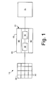
- Fig. 1 shows a known solar power generation system 10.
- the solar power generation system 10 may include one or more photovoltaic arrays 20.
- the photovoltaic arrays 20 each may have any number of photovoltaic cells 30 in any desired size and/or configuration. As described above, the photovoltaic cells 30 of the photovoltaic array 20 produce variable DC power based upon the local weather and other operating conditions.
- the solar power generation system 10 further includes a power conversion system 40.
- the power conversion system 40 includes the components required to convert the DC power from the photovoltaic array 20 to AC power.
- the power conversion system 40 may include a DC to DC converter 50.
- the DC to DC converter 50 may be coupled to the photovoltaic array 20 so as to condition the DC power.
- the DC to DC converter 50 may include a switching type regulator so as to regulate the DC voltage using a form of pulse width modulation control and other types of devices.
- the DC to DC converter 50 also may include a power converter, or step up converter, that may be operable to boost the DC power from a first voltage to a second voltage and the like. Other configurations may be used herein.
- the power conversion system 40 further may include a DC to AC inverter 60.
- the DC to AC inverter 60 may convert the relatively stable DC power produced by the DC to DC converter 50 into AC power.
- the DC to AC inverter 60 may provide AC power in the form of a 60 Hertz sinusoidal wave and the like. Other types of outputs and configurations may be used herein.
- the power conversion system 40 may be housed in an enclosure 65.
- the enclosure 65 may be largely airtight and/or hermetically sealed so as to eliminate ambient airflow and associated filtering efforts.
- the solar power generation system 10 thus provides AC power to a utility grid 70, another type of load, or otherwise as may be desired. Other configurations may be used herein.
- the solar power generation system 10 further may include a thermal management system 80.
- the thermal management system 80 may include one or more heat exchangers 90 positioned within the enclosure 65.
- the heat exchangers 90 may be liquid to air exchangers, liquid to liquid exchangers, and/or other types of configurations and devices.
- the heat exchangers 90 function to remove heat from the components of the power conversion system 40 in a conventional manner as described above (above ground). Other types of cooling systems may be used herein.
- the thermal management system 80 further may include one or more heaters 95 positioned about the power conversion system 40 to warm the components therein.
- the heater 95 may be a resistive type device or other type of heating device.
- the thermal management system 80 also may use heat exchangers 90 so as to provide heat. Other types of heating systems may be used herein.
- the thermal management system 80 may be powered by the overall solar power generation system 10 or otherwise by an external source.
- Fig. 2 shows a geothermal cooling and heating system 100 as is described herein.
- the geothermal cooling and heating system 100 may be used with the solar power generation system 10 largely as described above and/or with similar types of components.
- the solar power generation system 10 may include the photovoltaic array 20 in communication with the power conversion system 40 within the enclosure 65.
- the enclosure 65 may be largely airtight and/or hermetically sealed.
- the solar power generation system 10 thus may provide AC power to the utility grid 70 as described above.
- the geothermal cooling and heating system 100 may include a number of pipes 110.
- the pipes 110 may be largely buried in the ground 120 in a trench or the like such that the ground 120 acts as a heat source or heat sink.
- the pipes 110 may be arranged in a closed loop field, an open loop field, a horizontal closed loop field, a vertical closed loop field, a slinky closed loop field, or in any desired configuration.
- the pipes 110 also may be positioned within a water source so as to use the water source as the heat source or heat sink.
- the pipes 110 may have any length, diameter, and configuration. Any number of pipes 110 may be used.
- the pipes 110 may extend about ten (10) feet (about three (3) meters) into the ground 120 although any depth below the frost line may be used.
- One set of pipes 110 of a geothermal system 100 may be used with several solar power generation systems 10, power conversion systems 40, and the like.
- the geothermal system 100 further may include a thermal management system 130.
- the thermal management system 130 may be largely similar to the thermal management system 80 described above and the like.
- the thermal management system 130 may be positioned within the enclosure 65 about the power conversion system 40 of the solar power generation system 10 so as to exchange heat therewith.
- the thermal management system 130 may include a heat exchanger 140 in communication with the pipes 110.
- the heat exchanger 140 may be a liquid to air exchanger, a liquid to liquid exchanger, and/or other types of configurations and devices.
- the heat exchanger 140 may be in the form of a cold plate, a series of coils, or any desired configuration or combinations thereof.
- the geothermal system 100 may include a thermal transfer medium 150 running through the pipes 110 and the heat exchanger 140.
- the thermal transfer medium may be ionized water, de-ionized water, antifreeze, oil, or any desired medium.
- the thermal transfer medium 150 may be electrically conductive or non-conductive.
- the thermal transfer medium 150 may be pumped through the pipes 110 and the heat exchanger 140 via a pump 160 or a similar type of fluid movement device.
- the upper ten (10) feet (about three (3) meters) of the ground 120 maintains a nearly constant temperature of between about 50 and 60 degrees Fahrenheit (about 10 to 16 degrees Celsius) and may serve as the heat source or heat sink depending upon the weather conditions on the surface.
- the thermal transfer medium 150 thus may be pumped through the pipes 110 in the ground 120 and through the heat exchanger 140 positioned about the power conversion system 40.
- the geothermal system 100 thus may transfer the heat generated by the power conversion system 40 to the ground 120 when the ground 120 is cooler than the surface and/or the components.
- the heat generated by the DC to DC converter 50, the DC to AC inverter 60, and other types of conversion components such as the semiconductors, the inductors, the capacitors, and the like within the enclosure 65 may be transferred to the ground 120 where the heat may be dissipated within the pipes 110.
- heating also may be provided to the power conversion system 40 when the ground 120 is warmer than the surface and/or the components.
- the geothermal system 100 thus may provide a constant inflow temperature to the power conversion system 40 and other components of the solar power generation system 10 irrespective of environmental conditions.
- the cooling and heating equipment 90, 95 formerly used for large temperature variations thus may be avoided as well as the associated operating and maintenance costs.
- the overall solar power generation system 10 thus may be designed for a narrow temperature range so as to minimize further the costs.
- geothermal system 100 has been described in the context of the solar power generation system 10, the system 100 may be applicable to battery storage applications, electric generator applications, fuel cell applications, high voltage DC transmission systems, variable speed drives, and the like. Specifically, the geothermal system 100 may be used in any solar application and any other application in which the power conversion systems and other systems may be enclosed and/or not in contact with the outside environment.
Applications Claiming Priority (1)
| Application Number | Priority Date | Filing Date | Title |
|---|---|---|---|
| US12/560,564 US20100139736A1 (en) | 2009-09-16 | 2009-09-16 | Geothermal heating and cooling management system |
Publications (2)
| Publication Number | Publication Date |
|---|---|
| EP2306119A2 true EP2306119A2 (de) | 2011-04-06 |
| EP2306119A3 EP2306119A3 (de) | 2014-01-15 |
Family
ID=42229714
Family Applications (1)
| Application Number | Title | Priority Date | Filing Date |
|---|---|---|---|
| EP10175693.0A Withdrawn EP2306119A3 (de) | 2009-09-16 | 2010-09-08 | Steuerungssystem für mit Erdwärme betriebenes Heiz- und Kühlsystem |
Country Status (4)
| Country | Link |
|---|---|
| US (1) | US20100139736A1 (de) |
| EP (1) | EP2306119A3 (de) |
| CN (1) | CN102025260A (de) |
| AU (1) | AU2010219420A1 (de) |
Families Citing this family (8)
| Publication number | Priority date | Publication date | Assignee | Title |
|---|---|---|---|---|
| US8776867B2 (en) * | 2009-03-23 | 2014-07-15 | John Stojanowski | Modular, stackable, geothermal block heat exchange system with solar assist |
| CN102086967B (zh) * | 2010-11-20 | 2013-01-02 | 盘锦思创空调科技有限公司 | 一种用于原油伴热的地源热泵系统 |
| EP2482626B1 (de) * | 2011-01-31 | 2014-06-11 | ABB Oy | Verfahren und Anordnung in Verbindung mit einem Solarenergiesystem |
| CN102435033B (zh) * | 2011-12-01 | 2014-05-14 | 国家电网公司 | 密闭式循环水冷却装置及其方法 |
| CN103292517B (zh) * | 2012-03-05 | 2015-12-09 | 北京兆阳光热技术有限公司 | 一种应用于太阳能发电系统的地源冷却装置 |
| US9351430B2 (en) * | 2013-06-13 | 2016-05-24 | Microsoft Technology Licensing, Llc | Renewable energy based datacenter cooling |
| CN103324216A (zh) * | 2013-06-17 | 2013-09-25 | 上海大学 | 一种太阳能最大功率发电温控系统及方法 |
| US11224145B2 (en) * | 2018-08-01 | 2022-01-11 | Nautilus True, Llc | Datacenter geothermal cooling system and method |
Family Cites Families (11)
| Publication number | Priority date | Publication date | Assignee | Title |
|---|---|---|---|---|
| US6866092B1 (en) * | 1981-02-19 | 2005-03-15 | Stephen Molivadas | Two-phase heat-transfer systems |
| US4449572A (en) * | 1981-03-27 | 1984-05-22 | Ladek Corporation | Subterranean heating and cooling system |
| US5216577A (en) * | 1991-10-25 | 1993-06-01 | Comtronics Enclosures Corporation | Stable thermal enclosure for outdoor electronics |
| IL129392A0 (en) * | 1999-04-11 | 2000-06-01 | Eci Telecom Ltd | System and method for heat exchanging |
| DE10044096A1 (de) * | 2000-09-07 | 2002-04-04 | Aloys Wobben | Inselnetz und Verfahren zum Betrieb eines Inselnetzes |
| DE10153933A1 (de) * | 2000-11-11 | 2002-05-29 | Rittal Gmbh & Co Kg | Schaltschrank mit einer Klimatisierungseinrichtung |
| US6989989B2 (en) * | 2003-06-17 | 2006-01-24 | Utc Power Llc | Power converter cooling |
| AT412818B (de) * | 2004-04-28 | 2005-07-25 | Karl-Heinz Dipl Ing Hinrichs | Heiz- und warmwasserbereitungsanlage und verfahren zum betrieb einer solchen anlage |
| US20080154801A1 (en) * | 2006-12-22 | 2008-06-26 | Genedics Llc | System and Method for Creating a Geothermal Roadway Utility with Alternative Energy Pumping Billing System |
| US20090094981A1 (en) * | 2007-10-12 | 2009-04-16 | General Electric Company | Wind turbine geothermal heating and cooling system |
| US20100302728A1 (en) * | 2007-11-28 | 2010-12-02 | Voltwerk Electronics Gmbh | Chassis for inverter |
-
2009
- 2009-09-16 US US12/560,564 patent/US20100139736A1/en not_active Abandoned
-
2010
- 2010-09-08 EP EP10175693.0A patent/EP2306119A3/de not_active Withdrawn
- 2010-09-14 AU AU2010219420A patent/AU2010219420A1/en not_active Abandoned
- 2010-09-16 CN CN2010102934898A patent/CN102025260A/zh active Pending
Non-Patent Citations (1)
| Title |
|---|
| None |
Also Published As
| Publication number | Publication date |
|---|---|
| AU2010219420A1 (en) | 2011-03-31 |
| CN102025260A (zh) | 2011-04-20 |
| EP2306119A3 (de) | 2014-01-15 |
| US20100139736A1 (en) | 2010-06-10 |
Similar Documents
| Publication | Publication Date | Title |
|---|---|---|
| EP2306119A2 (de) | Steuerungssystem für mit Erdwärme betriebenes Heiz- und Kühlsystem | |
| CN201332372Y (zh) | 利用液冷循环冷却的余热温差发电系统 | |
| US10104814B2 (en) | System and method for cooling electrical components of a power converter | |
| CN102647122B (zh) | 太阳能光伏-温差自动控温联合发电装置 | |
| JP2020520547A (ja) | 熱調節型モジュール式エネルギー貯蔵装置および方法 | |
| US20140299174A1 (en) | System of geothermal cooling for photovoltaic solar panels and application thereof | |
| US20180292097A1 (en) | Passive energy storage systems and related methods | |
| CN201656818U (zh) | 太阳能光伏及温差发电驱动型直流冰箱 | |
| US20050051208A1 (en) | System for transferring heat in a thermoelectric generator system | |
| CN102128139A (zh) | 利用塔筒壁冷却的风力发电机 | |
| CN102355168B (zh) | 一种太阳能温差发电装置 | |
| CN1667935A (zh) | 用于高温气冷堆事故后监测仪表电源的温差发电器 | |
| CN102664209A (zh) | 太阳能光伏电池冷却装置 | |
| US10590916B2 (en) | Multisiphon passive cooling system | |
| US10727777B2 (en) | System and apparatus for generating electricity with integrated circuitry | |
| Aghakhani et al. | Experimental study of the effect of simultaneous application of the air-and water-cooled flow on efficiency in a Photovoltaic thermal solar collector with porous plates | |
| CN108599720A (zh) | 一种密排cpv组件散热装置 | |
| US20120075901A1 (en) | Geothermally cooled power conversion system | |
| CN1912501A (zh) | 小户型太阳光热转换致冷系统 | |
| KR101494241B1 (ko) | 폐열 회수 발전 시스템 | |
| CN206237363U (zh) | 一种光伏电池组件用节能型水冷散热降温装置 | |
| CN115568165A (zh) | 一种用于变流器的恒温控制装置及其安装结构 | |
| Leow et al. | PIC 18F4550 controlled solar panel cooling system using DC hybrid | |
| CN215120147U (zh) | 储能电站 | |
| CN106656026A (zh) | 一种光伏电池组件用节能型水冷散热降温装置 |
Legal Events
| Date | Code | Title | Description |
|---|---|---|---|
| PUAI | Public reference made under article 153(3) epc to a published international application that has entered the european phase |
Free format text: ORIGINAL CODE: 0009012 |
|
| AK | Designated contracting states |
Kind code of ref document: A2 Designated state(s): AL AT BE BG CH CY CZ DE DK EE ES FI FR GB GR HR HU IE IS IT LI LT LU LV MC MK MT NL NO PL PT RO SE SI SK SM TR |
|
| AX | Request for extension of the european patent |
Extension state: BA ME RS |
|
| PUAL | Search report despatched |
Free format text: ORIGINAL CODE: 0009013 |
|
| AK | Designated contracting states |
Kind code of ref document: A3 Designated state(s): AL AT BE BG CH CY CZ DE DK EE ES FI FR GB GR HR HU IE IS IT LI LT LU LV MC MK MT NL NO PL PT RO SE SI SK SM TR |
|
| AX | Request for extension of the european patent |
Extension state: BA ME RS |
|
| RIC1 | Information provided on ipc code assigned before grant |
Ipc: H02M 7/00 20060101ALI20131210BHEP Ipc: F24J 3/08 20060101AFI20131210BHEP |
|
| STAA | Information on the status of an ep patent application or granted ep patent |
Free format text: STATUS: THE APPLICATION IS DEEMED TO BE WITHDRAWN |
|
| 18D | Application deemed to be withdrawn |
Effective date: 20140401 |