EP2305610A1 - Sterilizing/antibacterializing device - Google Patents
Sterilizing/antibacterializing device Download PDFInfo
- Publication number
- EP2305610A1 EP2305610A1 EP09802764A EP09802764A EP2305610A1 EP 2305610 A1 EP2305610 A1 EP 2305610A1 EP 09802764 A EP09802764 A EP 09802764A EP 09802764 A EP09802764 A EP 09802764A EP 2305610 A1 EP2305610 A1 EP 2305610A1
- Authority
- EP
- European Patent Office
- Prior art keywords
- bacterialization
- sterilization
- water
- active oxygen
- oxygen species
- Prior art date
- Legal status (The legal status is an assumption and is not a legal conclusion. Google has not performed a legal analysis and makes no representation as to the accuracy of the status listed.)
- Granted
Links
Images


Classifications
-
- C—CHEMISTRY; METALLURGY
- C02—TREATMENT OF WATER, WASTE WATER, SEWAGE, OR SLUDGE
- C02F—TREATMENT OF WATER, WASTE WATER, SEWAGE, OR SLUDGE
- C02F1/00—Treatment of water, waste water, or sewage
- C02F1/46—Treatment of water, waste water, or sewage by electrochemical methods
- C02F1/461—Treatment of water, waste water, or sewage by electrochemical methods by electrolysis
- C02F1/467—Treatment of water, waste water, or sewage by electrochemical methods by electrolysis by electrochemical disinfection; by electrooxydation or by electroreduction
- C02F1/4672—Treatment of water, waste water, or sewage by electrochemical methods by electrolysis by electrochemical disinfection; by electrooxydation or by electroreduction by electrooxydation
-
- C—CHEMISTRY; METALLURGY
- C02—TREATMENT OF WATER, WASTE WATER, SEWAGE, OR SLUDGE
- C02F—TREATMENT OF WATER, WASTE WATER, SEWAGE, OR SLUDGE
- C02F1/00—Treatment of water, waste water, or sewage
- C02F1/46—Treatment of water, waste water, or sewage by electrochemical methods
- C02F1/461—Treatment of water, waste water, or sewage by electrochemical methods by electrolysis
- C02F1/46104—Devices therefor; Their operating or servicing
-
- C—CHEMISTRY; METALLURGY
- C02—TREATMENT OF WATER, WASTE WATER, SEWAGE, OR SLUDGE
- C02F—TREATMENT OF WATER, WASTE WATER, SEWAGE, OR SLUDGE
- C02F1/00—Treatment of water, waste water, or sewage
- C02F1/46—Treatment of water, waste water, or sewage by electrochemical methods
- C02F1/461—Treatment of water, waste water, or sewage by electrochemical methods by electrolysis
- C02F1/46104—Devices therefor; Their operating or servicing
- C02F1/46109—Electrodes
- C02F2001/46123—Movable electrodes
-
- C—CHEMISTRY; METALLURGY
- C02—TREATMENT OF WATER, WASTE WATER, SEWAGE, OR SLUDGE
- C02F—TREATMENT OF WATER, WASTE WATER, SEWAGE, OR SLUDGE
- C02F1/00—Treatment of water, waste water, or sewage
- C02F1/46—Treatment of water, waste water, or sewage by electrochemical methods
- C02F1/461—Treatment of water, waste water, or sewage by electrochemical methods by electrolysis
- C02F1/46104—Devices therefor; Their operating or servicing
- C02F1/46109—Electrodes
- C02F2001/46133—Electrodes characterised by the material
Definitions
- the present invention relates to sterilization and anti-bacterialization equipment which makes possible continuous creation of active oxygen species, which are useful to sterilization and anti-bacterialization.
- the electrodes are composed of a cathode which is capable of creating active oxygen species and an anode which is composed of low surface-resistant metal or carbon material.
- active oxygen species such as superoxide (O 2 -), hydroxyl-radical ( ⁇ OH) and hydrogen peroxide (H 2 O 2 ) are created. These active oxygen species make the microbes in the water to be treated inactive and sterilization and anti-bacterialization of the water is performed.
- the objective of the present invention is to provide equipment capable of creating necessary amount of active oxygen species for sterilization and anti-bacterialization in the water to be treated, for long time. This can be attained by making the amount of active oxygen species consumed at the anode electrode restrained and the amount of active oxygen species in appearance close to the amount actually created with the cathode electrode, so that the creating efficiency is improved.
- the sterilization and anti-bacterialization equipment according to the present invention is provided with an anode electrode and a cathode electrode capable of creating active oxygen species.
- the anode electrode is made of an electrically conductive material which is mainly made of a polymeric material.
- Oxidation reaction usually occurs with the anode electrode; for example, chlorine and hydroxide in tap water supply electrons.
- the active oxygen species created with the cathode electrode are spread in the water to be treated and it is expected that they will make microbes such as bacteria inactive.
- the movement of the active oxygen species spread in a solvent can not be controlled, part of them are practically consumed in the oxidation reactions of the anode electrode.
- sterilizationand anti-bacterialization equipment is provided with the anode electrode made of a polymeric material as a main material (a base material), which is hardly oxidized by the active oxygen species, it becomes possible that consumptive reaction of active oxygen species created with the cathode electrode is restrained, the amount of created active oxygen species in appearance is increased, and therefore the efficiency of the actual creation of active oxygen species can be improved. Consequently, because a large amount of active oxygen species can stably exist in the water to be treated, the capability of sterilization and anti-bacterialization of the water improves.
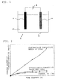
- Fig.1 is a schematic constitution diagram in accordance with a first embodiment of the present invention.
- the sterilization and anti-bacterialization equipment 1 includes a reaction chamber 3 for storing water to be treated 2 and creating active oxygen species, a pair of electrodes consisting of a cathode electrode 4 having capability of creating active oxygen species and an anode electrode 5, both of which are disposed such that at least some part of them are immersed in the water 2, and a power source 6 for energizing said electrodes 4 and 5.
- the cathode electrode 4 is made of carbon, metal or other electrically conductive material. It is favorable that a material having the capability of catalysis, which makes active oxygen species such as superoxide (O 2 -), hydroxyl radial ( ⁇ OH) and hydrogen peroxide (H 2 O 2 ) ,which makes active oxygen species easily created, or an electrically conductive polymeric material such as polyaniline, be brought into contact with the surface of the cathode electrode 4.
- active oxygen species such as superoxide (O 2 -), hydroxyl radial ( ⁇ OH) and hydrogen peroxide (H 2 O 2 )
- an electrically conductive polymeric material such as polyaniline
- the anode electrode 5 is made of a polymeric material or a material mainly made of the polymeric material. It is not important whether the polymeric material used is electrically conductive or not. However, the electrode 5 needs to be electrically conductive. Therefore in case when a polymeric material without electrical conductivity is used for the electrode 5, it shall be manufactured by mixture with the electrically conductive material such as carbon-filler in order to add the electrical conductivity to the electrode 5.
- the resin provided with the electrical conductivity is designated as "electrically conductive resin” hereafter.
- the anode electrode can be made mainly of polymeric materials such as polypropylene (PP), PET and ABS resin, which have no electrical conductivity but property of acid-resistance or alkali-resistance, this structure can prevent the anode 5 from being corroded by the water to be treated or the active oxygen species.
- electrical conductivity, acid-resistance and alkali-resistance of the anode electrode 5 can be improved by making the anode electrode 5 manufactured by mixing electrically conductive polymer (such as polyaniline).
- the capability of creating active oxygen species was provided to the cathode electrode 4 by means that a material having the property of catalytic action, such as polyaniline, by which active oxygen species were produced by reduction of dissolved oxygen in the water to be treated, was brought into contact with the surface of the cathode electrode 4.
- a material having the property of catalytic action such as polyaniline, by which active oxygen species were produced by reduction of dissolved oxygen in the water to be treated.
- the same objective measurements by using the following four kinds of materials, carbon, metal (Ti) and the electrically conductive resins, (PP, ABS) were conducted. According to the measurements, as shown in Fig.
- the concentration of the hydrogen peroxide in the water to be treated became an equilibrium state after approximately five hours from the start of reaction.
- the amounts of hydrogen peroxide after three hours from the start of reaction were 1.7mg/L with the carbon (surface resistance 3 ⁇ ), 1.7mg/L with the metal (Ti, surface resistance 1 ⁇ ), 9.3mg/L with the electrically conductive resin (PP, surface resistance 35 ⁇ ) and 4.0mg/L with the electrically conductive resin (ABS, 60 ⁇ ).
- the created amount of hydrogen peroxide was measured with the anode electrode 5 of which the main constituent material was ABS resin and the surface resistance was 60-10 11 ⁇ . According to the measurements, as shown in Fig. 3 , the created amounts of hydrogen peroxide after three hours from the start of reaction were 3. 4mg/L with the surface resistance 60 ⁇ , 3. 7mg/L with the surface resistance 200 ⁇ and 1.1mg/L with the surface resistance 10 6 ⁇ . In these measurements, hydrogen peroxide was not created when ABS resin with surface resistance of 10 11 ⁇ was used, because the water between the two electrodes could not be energized at this time.
- the main composed material of the anode electrode 5 is a polymeric material
- consumptive reaction of the hydrogen peroxide on the surface of the anode electrode 5 can be restrained, and, therefore, the amount of hydrogen peroxide in the water to be treated is increased.
- the corrosion of the anode electrode 5 caused by the hydrogen peroxide created with the cathode electrode 4 can be prevented, when the polymeric material, which does not easily affect the consumption reaction of the hydrogen peroxide around the anode electrode 5, is used for the electrode 5 or a main material of the electrode 5.
- the efficient creation of hydrogen peroxide can be carried out, so that the capability of sterilization and anti-bacterialization of the sterilization and anti-bacterialization equipment can be improved. Consequently, as shown in Fig.3 , the decreased amount of hydrogen peroxide consumed on the surface of the anode electrode 5 is made more than the decreased amount of hydrogen peroxide created with the cathode electrode 4, by making the surface resistance of the anode electrode 5 set to be 0-10 4 ⁇ . As a result, the amount of usable hydrogen peroxide can be increased.
- the water to be treated 2 mentioned in the first embodiment includes not only tap water, groundwater, water for the industrial use and drinking water but also water in a pool or a bathhouse, seawater and water to be supplied to various kinds of industrial facilities.
- the microbes to be considered for the sterilization ⁇ anti-bacterialization action in the first embodiment are bacteria, hyphomycetes, colibacillus, yeast, unicellular organism, protozoa, virus and so forth.
- both electrodes 4 and 5 are not necessarily arranged oppositely to each other; moreover, more than two electrodes 4 and 5 may be disposed within the reaction chamber 3. Also, in the first embodiment, it is not necessary that the material having a property of catalysis such as polyaniline is attached to the cathode electrode 4.
- Fig.4 is a perspective view of a part of a sterilization and anti-bacterialization equipment in accordance with a second embodiment of the present invention, where water to be treated is sterilized and anti-bacterialized.
- an inner wall 8 of a tube 7, in which water to be treated flows is let to be a cathode electrode 4, having the capability of creation of the active oxygen species.
- an anode electrode 5 having a polygonal shaped outer circumference is disposed in the middle of the tube 7.
- the tube 7 plays the same roll as the reaction chamber 3 in Fig.1 .
- the sterilization and anti-bacterialization equipment in accordance with the second embodiment has a structure, in which the polygonal shaped anode electrode 5 is disposed in the middle of the tube 7, products created around the both electrodes can flow down without coming in contact with the opposed electrode. Also, the shape of the anode electrode 5 is polygonal, so that the area in contact with the water to be treated is increased.
- sterilization and anti-bacterialization can be efficiently carried out even in the reduced space
- sterilization and anti-bacterialization can be carried out in places such as the inside of a drain pipe of an air conditioner.
- Fig.5 is a perspective view of a part of a sterilization and anti-bacterialization equipment, in accordance with the third embodiment of the present invention, where water to be treated is sterilized and anti-bacterialized.
- This is a variation of the second embodiment, and the different point from the second embodiment is that a plurality of the anode electrodes 5 is disposed along the inner wall 8 of the tube 7.
- Fig.6 is explanatory diagrams of a first example (a) and a second example (b), each showing a part of the sterilization and anti-bacterialization equipment, in accordance with the third embodiment, where sterilization ⁇ anti-bacterialization of water to be treated is performed.
- the anode electrodes 5 can independently be installed inside the inner wall 8 of the tube 7 as shown in Fig. 6 (a) or can be connected to each other as shown in Fig.6 (b) .
- one another cathode electrode 4 can be additionally installed in the middle of the tube 7 in addition to the inner wall 8.
- it is favorable that the outer circumference of the tube 7 is wrapped with the insulated material such as rubber so as to present leakage of current.
- the anode electrodes 5 are located along the inner wall 8 of the tube 7 (the shape of the outer circumference of one anode electrode can be a circular cylinder or a polygon), products created around both of the anode electrodes 5 and the cathode electrode 4 can flow down without coming in contact with the other opposed electrodes.
- the contact area with the water to be treated 2 can be increased by means of a plurality of anode electrodes 5 installed. Consequently, the sterilization and anti-bacterialization effect of the sterilization and anti-bacterialization equipment in accordance with the third embodiment can be more than or equal to that of the equipment in accordance with the second embodiment.
- Fig.7 is a constitution side view (a) and a constitution front view (b), each showing a part of the sterilization and anti-bacterialization equipment in accordance with the fourth embodiment of the present invention, where sterilization and anti-bacterialization of water to be treated is performed.
- the water to be treated 2 is reserved in a reaction chamber 3, and a plurality of plate-shaped anode electrodes 5 are maintained in stationary conditions and disposed in parallel at equal intervals within the reaction chamber 3.
- a plurality of disk-shaped cathode electrodes 4, which are able to be rotated, are disposed between plate-shaped anode electrodes 5.
- the central part of each disk-shaped cathode electrode 4 is attached to the electrically conductive rotational shaft 9, and these electrodes are rotatable with the rotational shaft 9.
- this equipment is designed so that the upper part of the electrode 4 is located in air, and the lower part in the water.
- a part projected out of the surface of the water 2 and a part immersed in the water 2 exist by making the cathode electrode 4 rotatable. Since the cathode electrodes 4 are rotated around the rotational shaft 9, they can be positioned so that a part of them alternately comes into and goes out of the water 2. Furthermore, it is favorable that the twist of wiring caused by the disk rotation is prevented by making the rotational shaft 9 electrically conductive.
- the cathode electrode 4 can be immersed in the water 2, and brought in contact with the air as a whole, and, as a result, the efficient creation of active oxygen species are made possible.
- the cathode electrodes 4 can also be made of electrically conductive resins. Furthermore, the material used for the cathode or the anode, which was explained in the first embodiment, can also be utilized in the fourth embodiment.
Landscapes
- Chemical & Material Sciences (AREA)
- Chemical Kinetics & Catalysis (AREA)
- Electrochemistry (AREA)
- General Chemical & Material Sciences (AREA)
- Life Sciences & Earth Sciences (AREA)
- Hydrology & Water Resources (AREA)
- Engineering & Computer Science (AREA)
- Environmental & Geological Engineering (AREA)
- Water Supply & Treatment (AREA)
- Organic Chemistry (AREA)
- Water Treatment By Electricity Or Magnetism (AREA)
Abstract
Description
- The present invention relates to sterilization and anti-bacterialization equipment which makes possible continuous creation of active oxygen species, which are useful to sterilization and anti-bacterialization.
- There are conventional methods for creating active oxygen species, in which voltage is applied to electrodes immersed in water to be treated and active oxygen species are created by making use of electrolysis of water (see, for example, Patent Document 1). In these cases, the electrodes are composed of a cathode which is capable of creating active oxygen species and an anode which is composed of low surface-resistant metal or carbon material. With the cathode electrode, active oxygen species such as superoxide (O2-), hydroxyl-radical (·OH) and hydrogen peroxide (H2O2) are created. These active oxygen species make the microbes in the water to be treated inactive and sterilization and anti-bacterialization of the water is performed.
-
- [Patent Document 1] Japanese Unexamined Patent Application Publication No.
2003-000957 - In traditional methods, a lot of hydrogen and chlorine are produced as by-products. Since active oxygen species created with a cathode electrode were partly disappeared at an anode electrode, the amount of active oxygen species in appearance was less than the actual amount of active oxygen species created with the cathode electrode. For example, when carbon material is used for the anode electrode, the active oxygen species turn to carbon dioxide (CO2) in oxidizing reaction. Also, when relatively chemically stable metal, such as titanium is used for the anode electrode, the active oxygen species turn to metal oxide in oxidizing reaction. As a result of these phenomena, a problem such that the active oxygen species necessary for the performance capable of sterilization and anti-bacterialization could not stably created over a long period of time.
- The objective of the present invention is to provide equipment capable of creating necessary amount of active oxygen species for sterilization and anti-bacterialization in the water to be treated, for long time. This can be attained by making the amount of active oxygen species consumed at the anode electrode restrained and the amount of active oxygen species in appearance close to the amount actually created with the cathode electrode, so that the creating efficiency is improved.
- The sterilization and anti-bacterialization equipment according to the present invention is provided with an anode electrode and a cathode electrode capable of creating active oxygen species. In the sterilization and anti-bacterialization equipment in which active oxygen species are created by energizing the water intervening between both electrodes, the anode electrode is made of an electrically conductive material which is mainly made of a polymeric material.
- Oxidation reaction usually occurs with the anode electrode; for example, chlorine and hydroxide in tap water supply electrons. On the other hand, the active oxygen species created with the cathode electrode are spread in the water to be treated and it is expected that they will make microbes such as bacteria inactive. However, since the movement of the active oxygen species spread in a solvent can not be controlled, part of them are practically consumed in the oxidation reactions of the anode electrode.
Since sterilizationand anti-bacterialization equipment according to the present invention is provided with the anode electrode made of a polymeric material as a main material (a base material), which is hardly oxidized by the active oxygen species, it becomes possible that consumptive reaction of active oxygen species created with the cathode electrode is restrained, the amount of created active oxygen species in appearance is increased, and therefore the efficiency of the actual creation of active oxygen species can be improved. Consequently, because a large amount of active oxygen species can stably exist in the water to be treated, the capability of sterilization and anti-bacterialization of the water improves. -
- [
Fig.1 ]
Fig.1 is a constitution diagram in accordance with the first embodiment of the present invention. - [
Fig.2 ]
Fig.2 is a graph showing the relationship among the materials of an anode electrode, time from the start of the reaction and the amount of created hydrogen peroxide. - [
Fig.3 ]
Fig.3 is a graph showing the surface resistance of an anode electrode made of ABS resin and the amount of hydrogen peroxide created after three hours from the start of the reaction. - [
Fig.4 ]
Fig.4 is a perspective view showing a part of a sterilization and anti-bacterialization equipment in accordance with the second embodiment, where sterilization and anti-bacterialization are performed. - [
Fig.5 ]
Fig.5 is a perspective view showing a part of a sterilization and anti-bacterialization equipment in accordance with the third embodiment, where sterilization and anti-bacterialization are performed. - [
Fig.6 ]
Fig.6 is an explanatory diagram of a first example (a) and an explanatory diagram of a second example (b), each showing a part of sterilization and anti-bacterialization equipment in accordance with the third embodiment where sterilization and anti-bacterialization are performed. - [
Fig.7 ]
Fig.7 is a constitution side view (a) and a constitution front view (b), each showing the part of sterilization and anti-bacterialization equipment in accordance with the fourth embodiment, where sterilization and anti-bacterialization are performed. - Embodiments of the sterilization and anti-bacterialization equipment according to the present invention will be described hereunder with reference to the accompanying drawings.
-
Fig.1 is a schematic constitution diagram in accordance with a first embodiment of the present invention. The sterilization andanti-bacterialization equipment 1 includes areaction chamber 3 for storing water to be treated 2 and creating active oxygen species, a pair of electrodes consisting of acathode electrode 4 having capability of creating active oxygen species and ananode electrode 5, both of which are disposed such that at least some part of them are immersed in thewater 2, and apower source 6 for energizing saidelectrodes - The
cathode electrode 4 is made of carbon, metal or other electrically conductive material. It is favorable that a material having the capability of catalysis, which makes active oxygen species such as superoxide (O2-), hydroxyl radial (·OH) and hydrogen peroxide (H2O2) ,which makes active oxygen species easily created, or an electrically conductive polymeric material such as polyaniline, be brought into contact with the surface of thecathode electrode 4. - The
anode electrode 5 is made of a polymeric material or a material mainly made of the polymeric material. It is not important whether the polymeric material used is electrically conductive or not. However, theelectrode 5 needs to be electrically conductive. Therefore in case when a polymeric material without electrical conductivity is used for theelectrode 5, it shall be manufactured by mixture with the electrically conductive material such as carbon-filler in order to add the electrical conductivity to theelectrode 5. (The resin provided with the electrical conductivity is designated as "electrically conductive resin" hereafter.) Consequently, since the anode electrode can be made mainly of polymeric materials such as polypropylene (PP), PET and ABS resin, which have no electrical conductivity but property of acid-resistance or alkali-resistance, this structure can prevent theanode 5 from being corroded by the water to be treated or the active oxygen species. Also, electrical conductivity, acid-resistance and alkali-resistance of theanode electrode 5 can be improved by making theanode electrode 5 manufactured by mixing electrically conductive polymer (such as polyaniline). - By using the sterilization · anti-bacteria equipment as shown in
Fig.1 , the amount of created hydrogen peroxide (H2O2), which is one kind of active oxygen species, was measured. Here, the capability of creating active oxygen species was provided to thecathode electrode 4 by means that a material having the property of catalytic action, such as polyaniline, by which active oxygen species were produced by reduction of dissolved oxygen in the water to be treated, was brought into contact with the surface of thecathode electrode 4. Also, for theanode electrode 5, the same objective measurements by using the following four kinds of materials, carbon, metal (Ti) and the electrically conductive resins, (PP, ABS) were conducted. According to the measurements, as shown inFig. 2 , the concentration of the hydrogen peroxide in the water to be treated became an equilibrium state after approximately five hours from the start of reaction. The amounts of hydrogen peroxide after three hours from the start of reaction were 1.7mg/L with the carbon (surface resistance 3Ω), 1.7mg/L with the metal (Ti, surface resistance 1Ω), 9.3mg/L with the electrically conductive resin (PP, surface resistance 35Ω) and 4.0mg/L with the electrically conductive resin (ABS, 60Ω). As a result of these measurements, it was understood that the amount of created hydrogen peroxide in appearance varies depending on the material being used for theanode electrode 5, although the surface resistance of the anode affected this result. - Also, the created amount of hydrogen peroxide was measured with the
anode electrode 5 of which the main constituent material was ABS resin and the surface resistance was 60-1011Ω.
According to the measurements, as shown inFig. 3 , the created amounts of hydrogen peroxide after three hours from the start of reaction were 3. 4mg/L with the surface resistance 60Ω, 3. 7mg/L with the surface resistance 200Ω and 1.1mg/L with thesurface resistance 106Ω. In these measurements, hydrogen peroxide was not created when ABS resin with surface resistance of 1011Ω was used, because the water between the two electrodes could not be energized at this time.
According to these measurements, it was turned out that when the surface resistance of theanode electrode 5 was between 1Ω and 200Ω, the amount of hydrogen peroxide consumed on the surface ofanode electrode 5 was restrained, and, as a result of this, the amount of usable hydrogen peroxide was increased. Also, when the surface resistance of theelectrode 5 was between 200Ω and 106Ω, decreased of the amount of created hydrogen peroxide caused by decreasing the amount of electrons per unit time received by thecathode electrode 4 was more than decrease of the amount of hydrogen peroxide consumed on the surface of theanode electrode 5, so that the amount of usable hydrogen peroxide was consequently decreased. - By the reasons stated above, in case that the main composed material of the
anode electrode 5 is a polymeric material, in comparison with a case that the main composed material ofanode electrode 5 is not a polymeric material, consumptive reaction of the hydrogen peroxide on the surface of theanode electrode 5 can be restrained, and, therefore, the amount of hydrogen peroxide in the water to be treated is increased. In addition, it is possible that the corrosion of theanode electrode 5 caused by the hydrogen peroxide created with thecathode electrode 4 can be prevented, when the polymeric material, which does not easily affect the consumption reaction of the hydrogen peroxide around theanode electrode 5, is used for theelectrode 5 or a main material of theelectrode 5. Therefore, since the consumption reaction of hydrogen peroxide around theanode electrode 5 can be restrained by means of using the above mentioned constitution in the sterilization and anti-bacterialization equipment, the efficient creation of hydrogen peroxide can be carried out, so that the capability of sterilization and anti-bacterialization of the sterilization and anti-bacterialization equipment can be improved.
Consequently, as shown inFig.3 , the decreased amount of hydrogen peroxide consumed on the surface of theanode electrode 5 is made more than the decreased amount of hydrogen peroxide created with thecathode electrode 4, by making the surface resistance of theanode electrode 5 set to be 0-104Ω. As a result, the amount of usable hydrogen peroxide can be increased. - The water to be treated 2 mentioned in the first embodiment includes not only tap water, groundwater, water for the industrial use and drinking water but also water in a pool or a bathhouse, seawater and water to be supplied to various kinds of industrial facilities. Also, the microbes to be considered for the sterilization·anti-bacterialization action in the first embodiment are bacteria, hyphomycetes, colibacillus, yeast, unicellular organism, protozoa, virus and so forth.
Furthermore, in the first embodiment, bothelectrodes electrodes reaction chamber 3.
Also, in the first embodiment, it is not necessary that the material having a property of catalysis such as polyaniline is attached to thecathode electrode 4. -
Fig.4 is a perspective view of a part of a sterilization and anti-bacterialization equipment in accordance with a second embodiment of the present invention, where water to be treated is sterilized and anti-bacterialized. Here, an inner wall 8 of atube 7, in which water to be treated flows, is let to be acathode electrode 4, having the capability of creation of the active oxygen species. On the other hand, ananode electrode 5 having a polygonal shaped outer circumference is disposed in the middle of thetube 7. In this equipment, thetube 7 plays the same roll as thereaction chamber 3 inFig.1 . - Since the sterilization and anti-bacterialization equipment in accordance with the second embodiment has a structure, in which the polygonal shaped
anode electrode 5 is disposed in the middle of thetube 7, products created around the both electrodes can flow down without coming in contact with the opposed electrode. Also, the shape of theanode electrode 5 is polygonal, so that the area in contact with the water to be treated is increased. - In this constitution, because the water flowing down in the
tube 7 is not easily agitated, active oxygen species created with thecathode electrode 4 are hardly brought into contact with theanode electrode 5 and hardly consumed at theanode electrode 5. With this constitution, the amount of created active oxygen species in appearance can be made close to the actual amount of active oxygen species created, without some special measures to be taken such as setting ion-exchange membrane between thecathode electrode 4 and theanode electrode 5. Moreover, sufficient electron-receiving area can be secured even in the reduced space.
In addition, since some active oxygen species are created around the inner wall 8 of thetube 7, the chances of contact with the microbes in the water to be treated increase, and, therefore, the effect for the capability of sterilization and anti-bacterialization is improved. Also, since it is expected that sterilization and anti-bacterialization can be efficiently carried out even in the reduced space, sterilization and anti-bacterialization can be carried out in places such as the inside of a drain pipe of an air conditioner.
By making the sterilization and anti-bacterialization equipment constructed using the inner wall of thetube 7 as the one in the second embodiment, the efficient sterilization and anti-bacterialization can be carried out. -
Fig.5 is a perspective view of a part of a sterilization and anti-bacterialization equipment, in accordance with the third embodiment of the present invention, where water to be treated is sterilized and anti-bacterialized. This is a variation of the second embodiment, and the different point from the second embodiment is that a plurality of theanode electrodes 5 is disposed along the inner wall 8 of thetube 7. -
Fig.6 is explanatory diagrams of a first example (a) and a second example (b), each showing a part of the sterilization and anti-bacterialization equipment, in accordance with the third embodiment, where sterilization·anti-bacterialization of water to be treated is performed. Theanode electrodes 5 can independently be installed inside the inner wall 8 of thetube 7 as shown inFig. 6 (a) or can be connected to each other as shown inFig.6 (b) . Also, one anothercathode electrode 4 can be additionally installed in the middle of thetube 7 in addition to the inner wall 8.
Furthermore, in the second and the third embodiments, it is favorable that the outer circumference of thetube 7 is wrapped with the insulated material such as rubber so as to present leakage of current. - In the sterilization and anti-bacterialization equipment in accordance with the third embodiment, since the
anode electrodes 5 are located along the inner wall 8 of the tube 7 (the shape of the outer circumference of one anode electrode can be a circular cylinder or a polygon), products created around both of theanode electrodes 5 and thecathode electrode 4 can flow down without coming in contact with the other opposed electrodes. In addition, the contact area with the water to be treated 2 can be increased by means of a plurality ofanode electrodes 5 installed. Consequently, the sterilization and anti-bacterialization effect of the sterilization and anti-bacterialization equipment in accordance with the third embodiment can be more than or equal to that of the equipment in accordance with the second embodiment. -
Fig.7 is a constitution side view (a) and a constitution front view (b), each showing a part of the sterilization and anti-bacterialization equipment in accordance with the fourth embodiment of the present invention, where sterilization and anti-bacterialization of water to be treated is performed. Here, the water to be treated 2 is reserved in areaction chamber 3, and a plurality of plate-shapedanode electrodes 5 are maintained in stationary conditions and disposed in parallel at equal intervals within thereaction chamber 3. A plurality of disk-shapedcathode electrodes 4, which are able to be rotated, are disposed between plate-shapedanode electrodes 5.
The central part of each disk-shapedcathode electrode 4 is attached to the electrically conductive rotational shaft 9, and these electrodes are rotatable with the rotational shaft 9. Also, this equipment is designed so that the upper part of theelectrode 4 is located in air, and the lower part in the water. - In the sterilization and anti-bacterialization equipment in accordance with the fourth embodiment, a part projected out of the surface of the
water 2 and a part immersed in thewater 2 exist by making thecathode electrode 4 rotatable. Since thecathode electrodes 4 are rotated around the rotational shaft 9, they can be positioned so that a part of them alternately comes into and goes out of thewater 2. Furthermore, it is favorable that the twist of wiring caused by the disk rotation is prevented by making the rotational shaft 9 electrically conductive. - In this equipment constitution, water membrane is always formed on the surface of the part projected out of the surface of the
water 2, by adjusting the velocity of rotation, in order for thecathode electrode 4 not to be dried. Also, since thecathode electrodes 4, which have the property of creating active oxygen species, are rotatable, they periodically come in contact with a large amount of oxygen, and as a result, the efficient creation of active oxygen species is made possible.
Also, although inFig.7 , the upper part of the cathode electrode 4 (approximately two third of the entire electrode) is positioned in the air and the lower part (approximately one third) in thewater 2, the constitution of the equipment is not necessarily limited to this example. For instance, by making half of theentire cathode electrode 4 immersed in thewater 2, thecathode electrode 4 can be immersed in thewater 2, and brought in contact with the air as a whole, and, as a result, the efficient creation of active oxygen species are made possible. - Also, although the above mentioned first to the fourth embodiments were explained in the cases that the
anode electrodes 5 were made of electrically conductive resins, thecathode electrodes 4 can also be made of electrically conductive resins.
Furthermore, the material used for the cathode or the anode, which was explained in the first embodiment, can also be utilized in the fourth embodiment. - 1 sterilization and anti-bacterialization equipment, 2 water to be treated, 3 reaction chamber, 4 cathode electrode, 5 anode electrode, 6 power source, 7 tube, 8 inner wall of the tube, 9 rotational shaft
Claims (6)
- Sterilization and anti-bacterialization equipment (1) for creating active oxygen species, comprising
an anode electrode (5) and a cathode electrode (4) having the capability of creating active oxygen species,
water to be treated (2) intervening between said both electrodes, the water between said both electrodes being electrically energized to create active oxygen species, wherein:said anode electrode (5) is made of a polymeric material or mainly made of the polymeric material. - The sterilization and anti-bacterialization equipment (1) according to claim 1, wherein:said anode electrode (5) is made of a polymeric material mixed with an electrically conductive material.
- The sterilization and anti-bacterialization equipment (1) according to claim 1 or claim 2, wherein:said anode electrode (5) is made of a polymeric material having a property of acid-resistance and/or alkali-resistance.
- The sterilization and anti-bacterialization equipment (1) according to any one of claims 1 to 3, wherein:said cathode electrode (4) is disposed to be rotated freely around a rotational shaft (9) so that a part of it comes in and goes out of the water to be treated (2) and air alternately.
- The sterilization and anti-bacterialization equipment (1) according to claim 4, wherein:said rotational shaft (9) is made electrically conductive.
- The sterilization and anti-bacterialization equipment (1) according to any one of claims 1 to 5, wherein:the range of surface resistance of said anode electrode (5) lies between 0Ω and 104Ω.
Applications Claiming Priority (2)
| Application Number | Priority Date | Filing Date | Title |
|---|---|---|---|
| JP2008197689 | 2008-07-31 | ||
| PCT/JP2009/057107 WO2010013519A1 (en) | 2008-07-31 | 2009-04-07 | Sterilizing/antibacterializing device |
Publications (3)
| Publication Number | Publication Date |
|---|---|
| EP2305610A1 true EP2305610A1 (en) | 2011-04-06 |
| EP2305610A4 EP2305610A4 (en) | 2011-12-14 |
| EP2305610B1 EP2305610B1 (en) | 2021-03-24 |
Family
ID=41610229
Family Applications (1)
| Application Number | Title | Priority Date | Filing Date |
|---|---|---|---|
| EP09802764.2A Not-in-force EP2305610B1 (en) | 2008-07-31 | 2009-04-07 | Sterilizing/antibacterializing device |
Country Status (5)
| Country | Link |
|---|---|
| US (1) | US20110100889A1 (en) |
| EP (1) | EP2305610B1 (en) |
| JP (1) | JP5355572B2 (en) |
| CN (1) | CN102083755B (en) |
| WO (1) | WO2010013519A1 (en) |
Families Citing this family (3)
| Publication number | Priority date | Publication date | Assignee | Title |
|---|---|---|---|---|
| JP5116793B2 (en) * | 2010-03-30 | 2013-01-09 | 三菱電機株式会社 | Reactive oxygen species generator |
| RU2636483C2 (en) * | 2012-09-21 | 2017-11-23 | Реоксин Дискавериз Груп, Инк. | Cell for liquid electrolysis |
| CN103638884A (en) * | 2013-11-29 | 2014-03-19 | 南通诚信氨基酸有限公司 | Process improved system for producing praziquantel |
Family Cites Families (21)
| Publication number | Priority date | Publication date | Assignee | Title |
|---|---|---|---|---|
| US4384943A (en) * | 1980-09-11 | 1983-05-24 | The University Of Virginia Alumni Patents Foundation | Fluid treatment |
| US4436601A (en) * | 1981-07-24 | 1984-03-13 | Diamond Shamrock Corporation | Metal removal process |
| US5242571A (en) * | 1992-10-26 | 1993-09-07 | Asarco Incorporated | Method and apparatus for the electrolytic production of copper wire |
| JP3181796B2 (en) * | 1994-10-28 | 2001-07-03 | 日本電気株式会社 | Electrolyzed water production equipment |
| CN1172774A (en) * | 1996-08-07 | 1998-02-11 | 森田健一 | Method for degerming by water and processing device used by said method |
| CN2331659Y (en) * | 1998-01-24 | 1999-08-04 | 张策 | Plasma treatment machine for cooling water special used by electric power plant |
| JP2002177819A (en) * | 2000-12-08 | 2002-06-25 | Zeotekku Kenkyusho:Kk | Electrostatic coagulation/adsorption separator for impurity in liquid |
| US6692662B2 (en) * | 2001-02-16 | 2004-02-17 | Elecon, Inc. | Compositions produced by solvent exchange methods and uses thereof |
| JP2002317287A (en) * | 2001-04-18 | 2002-10-31 | Permelec Electrode Ltd | Electrolytic cell for preparation of hydrogen peroxide and method for producing hydrogen peroxide |
| WO2003000957A1 (en) * | 2001-06-21 | 2003-01-03 | Sanyo Electric Co., Ltd. | Electrolyzing electrode and production method therefor and electrolysis method using electrolyzing electrode and electrolysis solution producing device |
| JP2003000957A (en) | 2001-06-21 | 2003-01-07 | Aruze Corp | Server and character generation system for controlling a system for renting characters via a communication line |
| KR100407710B1 (en) * | 2001-11-08 | 2003-12-01 | (주) 테크윈 | Catalytic oxide anode manufacturing method by high temperature sintering |
| CN2527553Y (en) * | 2002-02-05 | 2002-12-25 | 周新华 | High voltage electrostatic water treatment ion bar |
| JP4116949B2 (en) * | 2003-07-29 | 2008-07-09 | ペルメレック電極株式会社 | Electrochemical sterilization and sterilization method |
| JP2005152867A (en) * | 2003-11-25 | 2005-06-16 | Mututry:Kk | Electrolytic water manufacturing means |
| JP2007046129A (en) * | 2005-08-11 | 2007-02-22 | Sanyo Electric Co Ltd | Electrode for electrolysis, and method for producing electrode for electrolysis |
| JP4649681B2 (en) * | 2005-09-02 | 2011-03-16 | 圀武 永良 | Electrolytic treatment equipment |
| MX2008014300A (en) * | 2006-05-08 | 2008-11-26 | Siemens Water Tech Corp | Electrolytic apparatus with polymeric electrode and methods of preparation and use. |
| JP2008095173A (en) * | 2006-09-13 | 2008-04-24 | Sanyo Electric Co Ltd | Electrode for electrolysis, electrolytic process using the electrode and electrolytic apparatus using them |
| CN100500585C (en) * | 2007-02-14 | 2009-06-17 | 浙江工业大学 | A kind of electrooxidation treatment method of wastewater containing chlorobenzene compounds |
| US8491709B2 (en) * | 2008-04-14 | 2013-07-23 | Mitsubishi Electric Corporation | Active oxygen generating device, humidifier, and air purification system with humidifier |
-
2009
- 2009-04-07 EP EP09802764.2A patent/EP2305610B1/en not_active Not-in-force
- 2009-04-07 WO PCT/JP2009/057107 patent/WO2010013519A1/en not_active Ceased
- 2009-04-07 JP JP2010522644A patent/JP5355572B2/en active Active
- 2009-04-07 US US12/997,771 patent/US20110100889A1/en not_active Abandoned
- 2009-04-07 CN CN2009801261186A patent/CN102083755B/en not_active Expired - Fee Related
Also Published As
| Publication number | Publication date |
|---|---|
| EP2305610A4 (en) | 2011-12-14 |
| US20110100889A1 (en) | 2011-05-05 |
| WO2010013519A1 (en) | 2010-02-04 |
| EP2305610B1 (en) | 2021-03-24 |
| CN102083755A (en) | 2011-06-01 |
| JP5355572B2 (en) | 2013-11-27 |
| JPWO2010013519A1 (en) | 2012-01-05 |
| CN102083755B (en) | 2013-09-04 |
Similar Documents
| Publication | Publication Date | Title |
|---|---|---|
| Turkay et al. | The application of an electro-peroxone process in water and wastewater treatment | |
| Kraft | Electrochemical water disinfection: a short review | |
| Nadais et al. | Bio-electro-Fenton process for the degradation of non-steroidal anti-inflammatory drugs in wastewater | |
| Ma et al. | Reduction of oxygen to H2O2 at carbon felt cathode in undivided cells. Effect of the ratio between the anode and the cathode surfaces and of other operative parameters | |
| US7491453B2 (en) | Bio-electrochemically assisted microbial reactor that generates hydrogen gas and methods of generating hydrogen gas | |
| Santoro et al. | Microbial desalination cells with efficient platinum‐group‐metal‐free cathode catalysts | |
| CN101423266B (en) | Wastewater treatment device of horizontal polar plate multi-electrodes electrocatalysis reactor | |
| Alaoui et al. | Activity of Pt/MnO2 electrode in the electrochemical degradation of methylene blue in aqueous solution | |
| CN104628090B (en) | A kind of bio-electrochemical reactor and the application in degraded Fluoronitrobenzene class waste water thereof | |
| Tatinclaux et al. | Electricity generation from wastewater using a floating air cathode microbial fuel cell | |
| Souza et al. | Removal of herbicide 2, 4-D using conductive-diamond sono-electrochemical oxidation | |
| Zhang et al. | Improving electricity production in tubular microbial fuel cells through optimizing the anolyte flow with spiral spacers | |
| Cheng et al. | Electrochemical degradation of the antibiotic metronidazole in aqueous solution by the Ti/SnO2–Sb–Ce anode | |
| WO2008059331A2 (en) | Bioelectrochemical reactor | |
| Gao et al. | A novel electro-catalytic degradation method of phenol wastewater with Ti/IrO2-Ta2O5 anodes in high-gravity fields | |
| US10347932B2 (en) | Method and apparatus for converting chemical energy stored in wastewater | |
| Walter et al. | Scalability of self-stratifying microbial fuel cell: Towards height miniaturisation | |
| EP2305610A1 (en) | Sterilizing/antibacterializing device | |
| Taskan et al. | Combination of a novel electrode material and artificial mediators to enhance power generation in an MFC | |
| de Moura et al. | Cl-mediated electrochemical oxidation for treating an effluent using platinum and diamond anodes | |
| CN106517440B (en) | A multifunctional and efficient device for generating hydroxyl radicals and its application | |
| Liu et al. | Enhanced electrochemical disinfection for decentralized sewage treatment through nickel foam cathode modified with CoFe2O4-spinel ferrite and multi-way carbon nanotubes | |
| Chang et al. | Performance of nano-and nonnano-catalytic electrodes for decontaminating municipal wastewater | |
| Agladze et al. | The “In-cell” and “Ex-cell” Fenton treatment of phenol, 4-chlorophenol and aniline | |
| CN117401781B (en) | A method for electromagnetic synergistic oxidation of organic matter in wastewater |
Legal Events
| Date | Code | Title | Description |
|---|---|---|---|
| PUAI | Public reference made under article 153(3) epc to a published international application that has entered the european phase |
Free format text: ORIGINAL CODE: 0009012 |
|
| 17P | Request for examination filed |
Effective date: 20101216 |
|
| AK | Designated contracting states |
Kind code of ref document: A1 Designated state(s): AT BE BG CH CY CZ DE DK EE ES FI FR GB GR HR HU IE IS IT LI LT LU LV MC MK MT NL NO PL PT RO SE SI SK TR |
|
| AX | Request for extension of the european patent |
Extension state: AL BA RS |
|
| DAX | Request for extension of the european patent (deleted) | ||
| A4 | Supplementary search report drawn up and despatched |
Effective date: 20111110 |
|
| RIC1 | Information provided on ipc code assigned before grant |
Ipc: C02F 1/46 20060101AFI20111104BHEP |
|
| 17Q | First examination report despatched |
Effective date: 20160831 |
|
| STAA | Information on the status of an ep patent application or granted ep patent |
Free format text: STATUS: EXAMINATION IS IN PROGRESS |
|
| REG | Reference to a national code |
Ref country code: DE Ref legal event code: R079 Ref document number: 602009063499 Country of ref document: DE Free format text: PREVIOUS MAIN CLASS: C02F0001460000 Ipc: C02F0001461000 |
|
| RIC1 | Information provided on ipc code assigned before grant |
Ipc: C02F 1/461 20060101AFI20200930BHEP Ipc: C02F 1/467 20060101ALI20200930BHEP |
|
| GRAP | Despatch of communication of intention to grant a patent |
Free format text: ORIGINAL CODE: EPIDOSNIGR1 |
|
| STAA | Information on the status of an ep patent application or granted ep patent |
Free format text: STATUS: GRANT OF PATENT IS INTENDED |
|
| INTG | Intention to grant announced |
Effective date: 20201109 |
|
| RIN1 | Information on inventor provided before grant (corrected) |
Inventor name: SAITO, MARI Inventor name: FURUHASHI, TAKUYA Inventor name: TAKEUCHI, SHIRO |
|
| GRAS | Grant fee paid |
Free format text: ORIGINAL CODE: EPIDOSNIGR3 |
|
| GRAA | (expected) grant |
Free format text: ORIGINAL CODE: 0009210 |
|
| STAA | Information on the status of an ep patent application or granted ep patent |
Free format text: STATUS: THE PATENT HAS BEEN GRANTED |
|
| AK | Designated contracting states |
Kind code of ref document: B1 Designated state(s): AT BE BG CH CY CZ DE DK EE ES FI FR GB GR HR HU IE IS IT LI LT LU LV MC MK MT NL NO PL PT RO SE SI SK TR |
|
| REG | Reference to a national code |
Ref country code: GB Ref legal event code: FG4D |
|
| REG | Reference to a national code |
Ref country code: CH Ref legal event code: EP |
|
| REG | Reference to a national code |
Ref country code: IE Ref legal event code: FG4D |
|
| REG | Reference to a national code |
Ref country code: AT Ref legal event code: REF Ref document number: 1374332 Country of ref document: AT Kind code of ref document: T Effective date: 20210415 Ref country code: DE Ref legal event code: R096 Ref document number: 602009063499 Country of ref document: DE |
|
| REG | Reference to a national code |
Ref country code: SE Ref legal event code: TRGR |
|
| REG | Reference to a national code |
Ref country code: LT Ref legal event code: MG9D |
|
| PG25 | Lapsed in a contracting state [announced via postgrant information from national office to epo] |
Ref country code: HR Free format text: LAPSE BECAUSE OF FAILURE TO SUBMIT A TRANSLATION OF THE DESCRIPTION OR TO PAY THE FEE WITHIN THE PRESCRIBED TIME-LIMIT Effective date: 20210324 Ref country code: FI Free format text: LAPSE BECAUSE OF FAILURE TO SUBMIT A TRANSLATION OF THE DESCRIPTION OR TO PAY THE FEE WITHIN THE PRESCRIBED TIME-LIMIT Effective date: 20210324 Ref country code: GR Free format text: LAPSE BECAUSE OF FAILURE TO SUBMIT A TRANSLATION OF THE DESCRIPTION OR TO PAY THE FEE WITHIN THE PRESCRIBED TIME-LIMIT Effective date: 20210625 Ref country code: BG Free format text: LAPSE BECAUSE OF FAILURE TO SUBMIT A TRANSLATION OF THE DESCRIPTION OR TO PAY THE FEE WITHIN THE PRESCRIBED TIME-LIMIT Effective date: 20210624 Ref country code: NO Free format text: LAPSE BECAUSE OF FAILURE TO SUBMIT A TRANSLATION OF THE DESCRIPTION OR TO PAY THE FEE WITHIN THE PRESCRIBED TIME-LIMIT Effective date: 20210624 |
|
| PG25 | Lapsed in a contracting state [announced via postgrant information from national office to epo] |
Ref country code: LV Free format text: LAPSE BECAUSE OF FAILURE TO SUBMIT A TRANSLATION OF THE DESCRIPTION OR TO PAY THE FEE WITHIN THE PRESCRIBED TIME-LIMIT Effective date: 20210324 |
|
| REG | Reference to a national code |
Ref country code: NL Ref legal event code: MP Effective date: 20210324 |
|
| REG | Reference to a national code |
Ref country code: AT Ref legal event code: MK05 Ref document number: 1374332 Country of ref document: AT Kind code of ref document: T Effective date: 20210324 |
|
| PG25 | Lapsed in a contracting state [announced via postgrant information from national office to epo] |
Ref country code: NL Free format text: LAPSE BECAUSE OF FAILURE TO SUBMIT A TRANSLATION OF THE DESCRIPTION OR TO PAY THE FEE WITHIN THE PRESCRIBED TIME-LIMIT Effective date: 20210324 |
|
| PG25 | Lapsed in a contracting state [announced via postgrant information from national office to epo] |
Ref country code: LT Free format text: LAPSE BECAUSE OF FAILURE TO SUBMIT A TRANSLATION OF THE DESCRIPTION OR TO PAY THE FEE WITHIN THE PRESCRIBED TIME-LIMIT Effective date: 20210324 Ref country code: EE Free format text: LAPSE BECAUSE OF FAILURE TO SUBMIT A TRANSLATION OF THE DESCRIPTION OR TO PAY THE FEE WITHIN THE PRESCRIBED TIME-LIMIT Effective date: 20210324 Ref country code: CZ Free format text: LAPSE BECAUSE OF FAILURE TO SUBMIT A TRANSLATION OF THE DESCRIPTION OR TO PAY THE FEE WITHIN THE PRESCRIBED TIME-LIMIT Effective date: 20210324 Ref country code: AT Free format text: LAPSE BECAUSE OF FAILURE TO SUBMIT A TRANSLATION OF THE DESCRIPTION OR TO PAY THE FEE WITHIN THE PRESCRIBED TIME-LIMIT Effective date: 20210324 |
|
| PG25 | Lapsed in a contracting state [announced via postgrant information from national office to epo] |
Ref country code: PT Free format text: LAPSE BECAUSE OF FAILURE TO SUBMIT A TRANSLATION OF THE DESCRIPTION OR TO PAY THE FEE WITHIN THE PRESCRIBED TIME-LIMIT Effective date: 20210726 Ref country code: PL Free format text: LAPSE BECAUSE OF FAILURE TO SUBMIT A TRANSLATION OF THE DESCRIPTION OR TO PAY THE FEE WITHIN THE PRESCRIBED TIME-LIMIT Effective date: 20210324 Ref country code: SK Free format text: LAPSE BECAUSE OF FAILURE TO SUBMIT A TRANSLATION OF THE DESCRIPTION OR TO PAY THE FEE WITHIN THE PRESCRIBED TIME-LIMIT Effective date: 20210324 Ref country code: ES Free format text: LAPSE BECAUSE OF FAILURE TO SUBMIT A TRANSLATION OF THE DESCRIPTION OR TO PAY THE FEE WITHIN THE PRESCRIBED TIME-LIMIT Effective date: 20210324 Ref country code: IS Free format text: LAPSE BECAUSE OF FAILURE TO SUBMIT A TRANSLATION OF THE DESCRIPTION OR TO PAY THE FEE WITHIN THE PRESCRIBED TIME-LIMIT Effective date: 20210724 Ref country code: RO Free format text: LAPSE BECAUSE OF FAILURE TO SUBMIT A TRANSLATION OF THE DESCRIPTION OR TO PAY THE FEE WITHIN THE PRESCRIBED TIME-LIMIT Effective date: 20210324 |
|
| PG25 | Lapsed in a contracting state [announced via postgrant information from national office to epo] |
Ref country code: LU Free format text: LAPSE BECAUSE OF NON-PAYMENT OF DUE FEES Effective date: 20210407 |
|
| REG | Reference to a national code |
Ref country code: DE Ref legal event code: R097 Ref document number: 602009063499 Country of ref document: DE |
|
| REG | Reference to a national code |
Ref country code: BE Ref legal event code: MM Effective date: 20210430 |
|
| PG25 | Lapsed in a contracting state [announced via postgrant information from national office to epo] |
Ref country code: CH Free format text: LAPSE BECAUSE OF NON-PAYMENT OF DUE FEES Effective date: 20210430 Ref country code: MC Free format text: LAPSE BECAUSE OF FAILURE TO SUBMIT A TRANSLATION OF THE DESCRIPTION OR TO PAY THE FEE WITHIN THE PRESCRIBED TIME-LIMIT Effective date: 20210324 Ref country code: LI Free format text: LAPSE BECAUSE OF NON-PAYMENT OF DUE FEES Effective date: 20210430 Ref country code: DK Free format text: LAPSE BECAUSE OF FAILURE TO SUBMIT A TRANSLATION OF THE DESCRIPTION OR TO PAY THE FEE WITHIN THE PRESCRIBED TIME-LIMIT Effective date: 20210324 |
|
| PLBE | No opposition filed within time limit |
Free format text: ORIGINAL CODE: 0009261 |
|
| STAA | Information on the status of an ep patent application or granted ep patent |
Free format text: STATUS: NO OPPOSITION FILED WITHIN TIME LIMIT |
|
| PG25 | Lapsed in a contracting state [announced via postgrant information from national office to epo] |
Ref country code: SI Free format text: LAPSE BECAUSE OF FAILURE TO SUBMIT A TRANSLATION OF THE DESCRIPTION OR TO PAY THE FEE WITHIN THE PRESCRIBED TIME-LIMIT Effective date: 20210324 |
|
| 26N | No opposition filed |
Effective date: 20220104 |
|
| PG25 | Lapsed in a contracting state [announced via postgrant information from national office to epo] |
Ref country code: IE Free format text: LAPSE BECAUSE OF NON-PAYMENT OF DUE FEES Effective date: 20210407 |
|
| PG25 | Lapsed in a contracting state [announced via postgrant information from national office to epo] |
Ref country code: IS Free format text: LAPSE BECAUSE OF FAILURE TO SUBMIT A TRANSLATION OF THE DESCRIPTION OR TO PAY THE FEE WITHIN THE PRESCRIBED TIME-LIMIT Effective date: 20210724 |
|
| PG25 | Lapsed in a contracting state [announced via postgrant information from national office to epo] |
Ref country code: BE Free format text: LAPSE BECAUSE OF NON-PAYMENT OF DUE FEES Effective date: 20210430 |
|
| PG25 | Lapsed in a contracting state [announced via postgrant information from national office to epo] |
Ref country code: IT Free format text: LAPSE BECAUSE OF FAILURE TO SUBMIT A TRANSLATION OF THE DESCRIPTION OR TO PAY THE FEE WITHIN THE PRESCRIBED TIME-LIMIT Effective date: 20210324 |
|
| PGFP | Annual fee paid to national office [announced via postgrant information from national office to epo] |
Ref country code: FR Payment date: 20230309 Year of fee payment: 15 |
|
| PG25 | Lapsed in a contracting state [announced via postgrant information from national office to epo] |
Ref country code: HU Free format text: LAPSE BECAUSE OF FAILURE TO SUBMIT A TRANSLATION OF THE DESCRIPTION OR TO PAY THE FEE WITHIN THE PRESCRIBED TIME-LIMIT; INVALID AB INITIO Effective date: 20090407 Ref country code: CY Free format text: LAPSE BECAUSE OF FAILURE TO SUBMIT A TRANSLATION OF THE DESCRIPTION OR TO PAY THE FEE WITHIN THE PRESCRIBED TIME-LIMIT Effective date: 20210324 |
|
| PGFP | Annual fee paid to national office [announced via postgrant information from national office to epo] |
Ref country code: SE Payment date: 20230227 Year of fee payment: 15 Ref country code: GB Payment date: 20230302 Year of fee payment: 15 |
|
| P01 | Opt-out of the competence of the unified patent court (upc) registered |
Effective date: 20230512 |
|
| REG | Reference to a national code |
Ref country code: DE Ref legal event code: R084 Ref document number: 602009063499 Country of ref document: DE |
|
| PGFP | Annual fee paid to national office [announced via postgrant information from national office to epo] |
Ref country code: DE Payment date: 20230228 Year of fee payment: 15 |
|
| REG | Reference to a national code |
Ref country code: GB Ref legal event code: 746 Effective date: 20240328 |
|
| PG25 | Lapsed in a contracting state [announced via postgrant information from national office to epo] |
Ref country code: MK Free format text: LAPSE BECAUSE OF FAILURE TO SUBMIT A TRANSLATION OF THE DESCRIPTION OR TO PAY THE FEE WITHIN THE PRESCRIBED TIME-LIMIT Effective date: 20210324 |
|
| PG25 | Lapsed in a contracting state [announced via postgrant information from national office to epo] |
Ref country code: TR Free format text: LAPSE BECAUSE OF FAILURE TO SUBMIT A TRANSLATION OF THE DESCRIPTION OR TO PAY THE FEE WITHIN THE PRESCRIBED TIME-LIMIT Effective date: 20210324 |
|
| PG25 | Lapsed in a contracting state [announced via postgrant information from national office to epo] |
Ref country code: MT Free format text: LAPSE BECAUSE OF FAILURE TO SUBMIT A TRANSLATION OF THE DESCRIPTION OR TO PAY THE FEE WITHIN THE PRESCRIBED TIME-LIMIT Effective date: 20210324 |
|
| REG | Reference to a national code |
Ref country code: DE Ref legal event code: R119 Ref document number: 602009063499 Country of ref document: DE |
|
| REG | Reference to a national code |
Ref country code: SE Ref legal event code: EUG |
|
| GBPC | Gb: european patent ceased through non-payment of renewal fee |
Effective date: 20240407 |
|
| PG25 | Lapsed in a contracting state [announced via postgrant information from national office to epo] |
Ref country code: DE Free format text: LAPSE BECAUSE OF NON-PAYMENT OF DUE FEES Effective date: 20241105 |
|
| PG25 | Lapsed in a contracting state [announced via postgrant information from national office to epo] |
Ref country code: GB Free format text: LAPSE BECAUSE OF NON-PAYMENT OF DUE FEES Effective date: 20240407 |
|
| PG25 | Lapsed in a contracting state [announced via postgrant information from national office to epo] |
Ref country code: FR Free format text: LAPSE BECAUSE OF NON-PAYMENT OF DUE FEES Effective date: 20240430 |
|
| PG25 | Lapsed in a contracting state [announced via postgrant information from national office to epo] |
Ref country code: GB Free format text: LAPSE BECAUSE OF NON-PAYMENT OF DUE FEES Effective date: 20240407 Ref country code: FR Free format text: LAPSE BECAUSE OF NON-PAYMENT OF DUE FEES Effective date: 20240430 Ref country code: DE Free format text: LAPSE BECAUSE OF NON-PAYMENT OF DUE FEES Effective date: 20241105 |
|
| PG25 | Lapsed in a contracting state [announced via postgrant information from national office to epo] |
Ref country code: SE Free format text: LAPSE BECAUSE OF NON-PAYMENT OF DUE FEES Effective date: 20240408 |