EP2305445A1 - Key and method of manufacturing the same - Google Patents
Key and method of manufacturing the same Download PDFInfo
- Publication number
- EP2305445A1 EP2305445A1 EP10176358A EP10176358A EP2305445A1 EP 2305445 A1 EP2305445 A1 EP 2305445A1 EP 10176358 A EP10176358 A EP 10176358A EP 10176358 A EP10176358 A EP 10176358A EP 2305445 A1 EP2305445 A1 EP 2305445A1
- Authority
- EP
- European Patent Office
- Prior art keywords
- key
- layer
- manufacturing
- molded layer
- film
- Prior art date
- Legal status (The legal status is an assumption and is not a legal conclusion. Google has not performed a legal analysis and makes no representation as to the accuracy of the status listed.)
- Withdrawn
Links
Images





Classifications
-
- B—PERFORMING OPERATIONS; TRANSPORTING
- B29—WORKING OF PLASTICS; WORKING OF SUBSTANCES IN A PLASTIC STATE IN GENERAL
- B29C—SHAPING OR JOINING OF PLASTICS; SHAPING OF MATERIAL IN A PLASTIC STATE, NOT OTHERWISE PROVIDED FOR; AFTER-TREATMENT OF THE SHAPED PRODUCTS, e.g. REPAIRING
- B29C45/00—Injection moulding, i.e. forcing the required volume of moulding material through a nozzle into a closed mould; Apparatus therefor
- B29C45/16—Making multilayered or multicoloured articles
- B29C45/1671—Making multilayered or multicoloured articles with an insert
-
- B—PERFORMING OPERATIONS; TRANSPORTING
- B29—WORKING OF PLASTICS; WORKING OF SUBSTANCES IN A PLASTIC STATE IN GENERAL
- B29L—INDEXING SCHEME ASSOCIATED WITH SUBCLASS B29C, RELATING TO PARTICULAR ARTICLES
- B29L2031/00—Other particular articles
- B29L2031/46—Knobs or handles, push-buttons, grips
- B29L2031/466—Keypads, keytops
-
- H—ELECTRICITY
- H01—ELECTRIC ELEMENTS
- H01H—ELECTRIC SWITCHES; RELAYS; SELECTORS; EMERGENCY PROTECTIVE DEVICES
- H01H2229/00—Manufacturing
- H01H2229/044—Injection moulding
- H01H2229/046—Multi-colour or double shot injection moulding
-
- Y—GENERAL TAGGING OF NEW TECHNOLOGICAL DEVELOPMENTS; GENERAL TAGGING OF CROSS-SECTIONAL TECHNOLOGIES SPANNING OVER SEVERAL SECTIONS OF THE IPC; TECHNICAL SUBJECTS COVERED BY FORMER USPC CROSS-REFERENCE ART COLLECTIONS [XRACs] AND DIGESTS
- Y10—TECHNICAL SUBJECTS COVERED BY FORMER USPC
- Y10T—TECHNICAL SUBJECTS COVERED BY FORMER US CLASSIFICATION
- Y10T428/00—Stock material or miscellaneous articles
- Y10T428/24—Structurally defined web or sheet [e.g., overall dimension, etc.]
- Y10T428/24479—Structurally defined web or sheet [e.g., overall dimension, etc.] including variation in thickness
- Y10T428/24521—Structurally defined web or sheet [e.g., overall dimension, etc.] including variation in thickness with component conforming to contour of nonplanar surface
Definitions
- the present application relates to a key and a method of manufacturing the key.
- a typical input key is manufactured as follows. Molten plastic material is injection molded to form a plastic main body having a contact surface, and an ink layer is formed on the contact surface of the main body according to predetermined patterns to represent characters. However, with use, the ink layer may fade and eventually disappear.
- FIG. 1 is a cross section of one embodiment of a key including a preform, a first molded layer formed on a first side surface of the preform, a second molded layer formed on a second side surface of the perform, and a film.
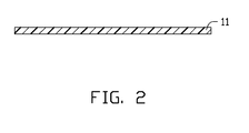
- FIG. 2 is a cross section of the film of FIG. 1 .
- FIG. 3 is a cross section of an ink layer formed on the film of FIG.2 .
- FIG. 4 is a cross section of the preform, the film, and the ink layer of FIG. 3 after hot pressing.
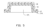
- FIG. 5 is a cross section of the first molded layer of FIG. 1 formed on the first side surface of the preform of FIG. 4 .
- FIG. 6 is a cross section of one embodiment of an injection mold used to manufacture the key of FIG. 1 .
- FIG. 7 is a cross section of a key having a stub bar manufactured by the injection mold of FIG. 6 .
- a key 10 includes a preform 15, a first molded layer 17, and a second molded layer 19.
- the preform 15 has a first side surface 153 and a second side surface 155 opposite to the first side surface 153.
- the first molded layer 17 is formed on the first side surface 153 by injection molding.
- the second molded layer 19 is formed on the second side surface 155 by injection molding.
- the preform 15, the first molded layer 17, and the second molded layer 19 cooperatively define a depression 21 to receive electronic components (not shown) positioned on an electronic device. A part of the first molded layer 17 forms the interior of the depression 21.
- a periphery of the first molded layer 17 forms an assembly portion 173 that engages with components of the electronic device to efficiently fix the key 10 to the electronic device.
- the preform 15 further includes a film 11 and an ink layer 13 formed on a side surface of the film 11.
- the preform 15 is made by hot pressing and cutting the film 11.
- the film 11 may be plastic, such as polycarbonate, acrylonitrile-butadiene-styrene terpolymer, polystyrene, poly vinyl chloride, polycarbonate, or acrylonitrile-butadiene-styrene.
- a thickness of ink layer 13 is about 0.1 millimeters (mm) to about 0.2mm.
- the first molded layer 17 may be plastic such as polycarbonate, acrylonitrile-butadiene-styrene terpolymer, polystyrene, poly vinyl chloride, polycarbonate, or acrylonitrile-butadiene-styrene.
- a thickness of the first molded layer 17 may be about 0.6mm to about 1.0mm.
- the second molded layer 19 is transparent or semi-transparent and may be plastic, such as polycarbonate, acrylonitrile-butadiene-styrene terpolymer, or poly-methylmethacrylate. Additionally, a portion of the second layer 19 on the periphery of the first molder layer 17 is substantially parallel to a portion of the ink layer 13 on the periphery of the first molder layer 17.
- One embodiment of a method for manufacturing the key 10 is described as follows.
- the film 11 is first provided.
- the ink layer 13 is then formed on a surface of the film 11 by printing.
- the film 11 is hot pressed to define a plurality of depressions 111 with a part of the ink layer 13 as the interior of the depressions 111.
- the film 11 is cut and a plurality of preforms 15 are formed.
- Each preform 15 corresponds to a depression 111 and has a first side surface 153 and a second side surface 155 opposite thereto.
- the first molded layer 17 is formed on the first side surface 153 of the preform 15 by injection molding.
- the first molded layer 17, the film 11, and the ink layer 13 cooperatively define the depressions 171.
- the injection mold 50 includes a cavity 51, a runner 53, and a gate 55 communicating the runner 53 with the cavity 51.
- the preform 15 and the first molded layer 17 are received in the cavity 51 such that the gate 55 substantially aligns with an edge of the preform 15 and is adjacent to the second side surface 155, and the gate 55 substantially parallels the ink layer 13.
- a molten material of a second molded layer 19 passes the runner 53 and the gate 55, and enters the cavity 51.
- the molten material of the second molded layer 19 is transparent or semi-transparent and may be plastic such as polycarbonate, acrylonitrile-butadiene-styrene terpolymer, or poly-methylmethacrylate.
- the molten material of the second molded layer 19 is solidified and the second molded layer 19 is formed on the second side surface 155 of the preform 15.
- a stub bar 23 is then cut off, thus yielding the key 10 as shown in FIG. 1 .
- the second molded layer 19 may be formed on the second side surface 155 of the preform 15 directly without additional steps and the ink layer 13 remains protected.
Landscapes
- Engineering & Computer Science (AREA)
- Manufacturing & Machinery (AREA)
- Mechanical Engineering (AREA)
- Injection Moulding Of Plastics Or The Like (AREA)
- Manufacture Of Switches (AREA)
Abstract
A key (10) includes a preform (15), a first molded layer (17) formed on a first side surface of the preform by injection molding, and a second molded layer (19) formed on the second side surface by injection molding. The preform, the first molded layer, and the second molded layer cooperatively define a depression (21). A periphery of the first molded layer forms an assembly portion. A portion of the second layer on the periphery of the first molder layer is substantially parallel to a portion of the ink layer (13) on the periphery of the first molder layer. A method of manufacturing the key (10) is also provided.
Description
- The present application relates to a key and a method of manufacturing the key.
- A typical input key is manufactured as follows. Molten plastic material is injection molded to form a plastic main body having a contact surface, and an ink layer is formed on the contact surface of the main body according to predetermined patterns to represent characters. However, with use, the ink layer may fade and eventually disappear.
- Therefore, there is room for improvement within the art.
- The components in the drawings are not necessarily drawn to scale, the emphasis instead being placed upon clearly illustrating the principles of the present disclosure.
-
FIG. 1 is a cross section of one embodiment of a key including a preform, a first molded layer formed on a first side surface of the preform, a second molded layer formed on a second side surface of the perform, and a film. -
FIG. 2 is a cross section of the film ofFIG. 1 . -
FIG. 3 is a cross section of an ink layer formed on the film ofFIG.2 . -
FIG. 4 is a cross section of the preform, the film, and the ink layer ofFIG. 3 after hot pressing. -
FIG. 5 is a cross section of the first molded layer ofFIG. 1 formed on the first side surface of the preform ofFIG. 4 . -
FIG. 6 is a cross section of one embodiment of an injection mold used to manufacture the key ofFIG. 1 . -
FIG. 7 is a cross section of a key having a stub bar manufactured by the injection mold ofFIG. 6 . - Referring to
FIG. 1 , akey 10 includes apreform 15, a first moldedlayer 17, and a second moldedlayer 19. Thepreform 15 has afirst side surface 153 and asecond side surface 155 opposite to thefirst side surface 153. The first moldedlayer 17 is formed on thefirst side surface 153 by injection molding. The second moldedlayer 19 is formed on thesecond side surface 155 by injection molding. Thepreform 15, the first moldedlayer 17, and the second moldedlayer 19 cooperatively define adepression 21 to receive electronic components (not shown) positioned on an electronic device. A part of the first moldedlayer 17 forms the interior of thedepression 21. - A periphery of the first molded
layer 17 forms anassembly portion 173 that engages with components of the electronic device to efficiently fix thekey 10 to the electronic device. - In the illustrated embodiment, the
preform 15 further includes afilm 11 and anink layer 13 formed on a side surface of thefilm 11. Thepreform 15 is made by hot pressing and cutting thefilm 11. Thefilm 11 may be plastic, such as polycarbonate, acrylonitrile-butadiene-styrene terpolymer, polystyrene, poly vinyl chloride, polycarbonate, or acrylonitrile-butadiene-styrene. A thickness ofink layer 13 is about 0.1 millimeters (mm) to about 0.2mm. - The first molded
layer 17 may be plastic such as polycarbonate, acrylonitrile-butadiene-styrene terpolymer, polystyrene, poly vinyl chloride, polycarbonate, or acrylonitrile-butadiene-styrene. - A thickness of the first molded
layer 17 may be about 0.6mm to about 1.0mm. - The second molded
layer 19 is transparent or semi-transparent and may be plastic, such as polycarbonate, acrylonitrile-butadiene-styrene terpolymer, or poly-methylmethacrylate. Additionally, a portion of thesecond layer 19 on the periphery of thefirst molder layer 17 is substantially parallel to a portion of theink layer 13 on the periphery of thefirst molder layer 17. - One embodiment of a method for manufacturing the
key 10 is described as follows. - Referring to
FIG. 2 , thefilm 11 is first provided. - Referring to
FIG. 3 , theink layer 13 is then formed on a surface of thefilm 11 by printing. - Referring to
FIG. 4 , thefilm 11 is hot pressed to define a plurality ofdepressions 111 with a part of theink layer 13 as the interior of thedepressions 111. Thefilm 11 is cut and a plurality ofpreforms 15 are formed. Eachpreform 15 corresponds to adepression 111 and has afirst side surface 153 and asecond side surface 155 opposite thereto. - Next, referring to
FIG. 5 , the first moldedlayer 17 is formed on thefirst side surface 153 of thepreform 15 by injection molding. The first moldedlayer 17, thefilm 11, and theink layer 13 cooperatively define thedepressions 171. - Referring to
FIG. 6 , aninjection mold 50 is provided. Theinjection mold 50 includes acavity 51, arunner 53, and agate 55 communicating therunner 53 with thecavity 51. - The
preform 15 and the first moldedlayer 17 are received in thecavity 51 such that thegate 55 substantially aligns with an edge of thepreform 15 and is adjacent to thesecond side surface 155, and thegate 55 substantially parallels theink layer 13. - Also referring to
FIG. 7 , a molten material of a second moldedlayer 19 passes therunner 53 and thegate 55, and enters thecavity 51. The molten material of the second moldedlayer 19 is transparent or semi-transparent and may be plastic such as polycarbonate, acrylonitrile-butadiene-styrene terpolymer, or poly-methylmethacrylate. The molten material of the second moldedlayer 19 is solidified and the second moldedlayer 19 is formed on thesecond side surface 155 of thepreform 15. - A
stub bar 23 is then cut off, thus yielding thekey 10 as shown inFIG. 1 . - Because the
gate 55 substantially aligns with an edge of thepreform 15 and is adjacent to thesecond side surface 155, and thegate 55 is substantially parallel to theink layer 13, the second moldedlayer 19 may be formed on thesecond side surface 155 of thepreform 15 directly without additional steps and theink layer 13 remains protected. - Finally, while various embodiments have been described and illustrated, the embodiments are not to be construed as being limited thereto. Various modifications can be made to the embodiments by those skilled in the art without departing from the true spirit and scope of the embodiments as defined by the appended claims.
Claims (19)
- A key, comprising:a preform having a first side surface and a second side surface opposite to the first side surface;a first molded layer formed on the first side surface by injection molding; anda second molded layer formed on the second side surface by injection molding, whereinthe preform, the first molded layer, and the second molded layer cooperatively define a depression; a periphery of the first molded layer forms an assembly portion; and a portion of the second layer on the periphery of the first molder layer is substantially parallel to a portion of the ink layer on the periphery of the first molder layer.
- The key of claim 1, wherein the preform comprises a film and an ink layer formed on a side surface of the film.
- The key of claim 2, wherein the film is polycarbonate, acrylonitrile-butadiene-styrene terpolymer, polystyrene, poly vinyl chloride, or polycarbonate/acrylonitrile-butadiene-styrene.
- The key of claim 2 or claim 3, wherein a thickness of the ink layer is in a range from about 0.1mm to about 0.2mm.
- The key of any preceding claim, wherein the first molded layer is selected from a group consisting of polycarbonate, acrylonitrile-butadiene-styrene terpolymer, polystyrene, poly vinyl chloride, polycarbonate, and acrylonitrile-butadiene-styrene.
- The key of any preceding claim, wherein a thickness of the first molded layer is about 0.6mm to about 1.0mm.
- A method for manufacturing a key, comprising steps of:providing a film;forming an ink layer on the film;hot pressing the film and cutting the film, thus forming a plurality of preforms, whereineach preform has a first side surface and a second side surface opposite to the first side surface, the ink layer being on the first side surface;forming a first molded layer on the ink layer by injection molding;providing an injection mold comprising a runner, a cavity, and a gate communicating the runner with the cavity;positioning the first molded layer and the preform in the cavity of the injection mold such that the gate of the injection mold substantially aligns with an edge of the preform and is adjacent to the second side surface of the preform;passing molten material through the runner and the gate into the cavity, thereby forming a second molded layer on the second side surface of the preform.
- The method of manufacturing the key of claim 7, wherein a material of the film is selected from a group consisting of polycarbonate, acrylonitrile-butadiene-styrene terpolymer, polystyrene, poly vinyl chloride, polycarbonate, and acrylonitrile-butadiene-styrene.
- The method of manufacturing the key of claim 7 or claim 8, wherein a thickness of the ink layer is about 0.1mm to about 0.2mm.
- The method of manufacturing the key of one of claims 7 to 9, wherein the ink layer is formed by printing.
- The method of manufacturing the key of one of claims 7 to 10, wherein a thickness of the first molded layer is about 1.5mm to about 2.5mm.
- The method of manufacturing the key of one of claims 7 to 11, wherein a plurality of depressions is defined in the film after hot pressing the film.
- The method of manufacturing the key of claim 12, wherein the ink layer is in the interior of the depression.
- The method of manufacturing the key of one of claims 7 to 13, wherein the first molded layer covers the ink layer completely.
- The method of manufacturing the key of one of claims 7 to 14, wherein a material of the first molded layer is selected from a group consisting of polycarbonate, acrylonitrile-butadiene-styrene terpolymer, polystyrene, poly vinyl chloride, polycarbonate, and acrylonitrile-butadiene-styrene.
- The method of manufacturing the key of one of claims 7 to 15, wherein a periphery of the first molded layer forms an assembly portion.
- The method of manufacturing the key of one of claims 7 to 16, wherein the second molded layer is transparent or semi-transparent.
- The method of manufacturing the key of one of claims 7 to 17, wherein a material of the second molded layer is selected from a group consisting of polycarbonate, acrylonitrile-butadiene-styrene terpolymer, and poly-methylmethacrylate.
- The method of manufacturing the key of one of claims 7 to 18, wherein a thickness of the second molded layer is about 0.6mm to about 1.0mm.
Applications Claiming Priority (1)
| Application Number | Priority Date | Filing Date | Title |
|---|---|---|---|
| CN2009103080581A CN102034625A (en) | 2009-09-30 | 2009-09-30 | Key manufacturing method and key manufactured by same |
Publications (1)
| Publication Number | Publication Date |
|---|---|
| EP2305445A1 true EP2305445A1 (en) | 2011-04-06 |
Family
ID=43413670
Family Applications (1)
| Application Number | Title | Priority Date | Filing Date |
|---|---|---|---|
| EP10176358A Withdrawn EP2305445A1 (en) | 2009-09-30 | 2010-09-13 | Key and method of manufacturing the same |
Country Status (4)
| Country | Link |
|---|---|
| US (1) | US20110076455A1 (en) |
| EP (1) | EP2305445A1 (en) |
| JP (1) | JP2011073438A (en) |
| CN (1) | CN102034625A (en) |
Families Citing this family (12)
| Publication number | Priority date | Publication date | Assignee | Title |
|---|---|---|---|---|
| US20120084966A1 (en) * | 2010-10-07 | 2012-04-12 | Microsoft Corporation | Method of making an interactive keyboard |
| CN104750259B (en) * | 2013-12-31 | 2018-10-02 | 群光电子股份有限公司 | Cover structure, input device and cover structure manufacturing method |
| CN103943397A (en) * | 2014-03-31 | 2014-07-23 | 美的集团股份有限公司 | Key and air conditioner |
| TWI494963B (en) * | 2014-05-02 | 2015-08-01 | Darfon Electronics Corp | Keycap and manufacturing method thereof |
| CN105782116B (en) * | 2014-12-24 | 2017-12-26 | 富瑞精密组件(昆山)有限公司 | The manufacture method of fan, fan frame and fan frame |
| CN105555068B (en) * | 2015-09-29 | 2018-09-07 | 宇龙计算机通信科技(深圳)有限公司 | A kind of double-color shell and mobile terminal |
| JP6341185B2 (en) * | 2015-11-24 | 2018-06-13 | マツダ株式会社 | Molding method of resin molded product and primary molded product used for the molding |
| TWI651745B (en) * | 2017-11-23 | 2019-02-21 | 世洋科技股份有限公司 | Method for manufacturing a key cap for a cover type keyboard device |
| CN107825651A (en) * | 2017-12-14 | 2018-03-23 | 显亮(昆山)汽车配件有限公司 | The former of staight shank anti-theft key |
| CN108878194B (en) * | 2018-07-26 | 2019-07-19 | 江苏传艺科技股份有限公司 | A kind of keyboard automated assembly line |
| CN109501125A (en) * | 2019-01-26 | 2019-03-22 | 庐江凯胜塑胶有限公司 | A kind of double-colored plus in-molded power button injection molding process method |
| CN111469543B (en) * | 2020-04-15 | 2020-11-17 | 张益国 | Keycap processing equipment |
Citations (3)
| Publication number | Priority date | Publication date | Assignee | Title |
|---|---|---|---|---|
| JP2000010483A (en) * | 1998-06-18 | 2000-01-14 | Bamboo Try Kk | Member for display and its production |
| JP2002052566A (en) * | 2000-07-27 | 2002-02-19 | Karo Sai | Method for molding key top |
| US20070170621A1 (en) * | 2006-01-21 | 2007-07-26 | Hon Hai Precision Industry Co., Ltd. | Cover and method for manufacturing the same |
Family Cites Families (7)
| Publication number | Priority date | Publication date | Assignee | Title |
|---|---|---|---|---|
| US3246066A (en) * | 1963-04-17 | 1966-04-12 | Jules P Gits | Method of making three dimensional molded articles |
| JP3514577B2 (en) * | 1995-11-15 | 2004-03-31 | 日本写真印刷株式会社 | Keypad and its manufacturing method |
| JP3514576B2 (en) * | 1996-01-18 | 2004-03-31 | 日本写真印刷株式会社 | Keypad manufacturing method and keypad |
| FR2778134B1 (en) * | 1998-04-29 | 2000-08-11 | Oreal | PROCESS AND DEVICE FOR THE MANUFACTURE OF PAINTED OR VARNISHED PARTS IN MOLDED PLASTIC MATERIAL |
| FI20002038A7 (en) * | 2000-09-15 | 2002-03-16 | Nokia Corp | Decorated injection molded product and method for making same |
| JP4119707B2 (en) * | 2002-08-02 | 2008-07-16 | ポリマテック株式会社 | Keypad, injection mold for resin key top, and method for manufacturing resin key top |
| JP4502172B2 (en) * | 2003-03-31 | 2010-07-14 | 株式会社吉野工業所 | Method for molding transparent lid with synthetic resin pattern and mold used in the molding method |
-
2009
- 2009-09-30 CN CN2009103080581A patent/CN102034625A/en active Pending
- 2009-11-24 US US12/624,410 patent/US20110076455A1/en not_active Abandoned
-
2010
- 2010-08-16 JP JP2010181618A patent/JP2011073438A/en not_active Withdrawn
- 2010-09-13 EP EP10176358A patent/EP2305445A1/en not_active Withdrawn
Patent Citations (3)
| Publication number | Priority date | Publication date | Assignee | Title |
|---|---|---|---|---|
| JP2000010483A (en) * | 1998-06-18 | 2000-01-14 | Bamboo Try Kk | Member for display and its production |
| JP2002052566A (en) * | 2000-07-27 | 2002-02-19 | Karo Sai | Method for molding key top |
| US20070170621A1 (en) * | 2006-01-21 | 2007-07-26 | Hon Hai Precision Industry Co., Ltd. | Cover and method for manufacturing the same |
Also Published As
| Publication number | Publication date |
|---|---|
| CN102034625A (en) | 2011-04-27 |
| US20110076455A1 (en) | 2011-03-31 |
| JP2011073438A (en) | 2011-04-14 |
Similar Documents
| Publication | Publication Date | Title |
|---|---|---|
| US20110076455A1 (en) | Key and method of manufacturing the same | |
| US20070172664A1 (en) | Cover and method for manufacturing the same | |
| US8142880B2 (en) | Housing for electronic device, mold for making the housing, and method for making the housing | |
| US20070170621A1 (en) | Cover and method for manufacturing the same | |
| US8655481B2 (en) | IMR (in-mold roller or in-mold release)/IMF (in-mold forming) making method using a digital printer printing and pre-forming technique | |
| US20120168339A1 (en) | Housing for electronic device and method for manufacturing the same | |
| US20100007045A1 (en) | Method for manufacturing shell with textured appearance | |
| US8242396B2 (en) | Keypad assembly and method for making the same | |
| US7486280B2 (en) | Contoured capacitive touch control panel | |
| CN1243632C (en) | Injection-moulded decorative product and its production method | |
| US20100055417A1 (en) | Decorative film and device housing using the same | |
| CN101218084B (en) | Die for injection compression molding | |
| KR100946282B1 (en) | Display window formed with a three-dimensional logo and its manufacturing method | |
| TWI223767B (en) | Improved key cap of keyboard and method of manufacture | |
| CN103660132A (en) | In molding label product and injection molding method thereof | |
| CN101138929B (en) | A kind of injection molding part and its manufacturing method | |
| JP2002156912A (en) | Protecting panel of display window of electronic instrument | |
| CN101184608B (en) | System, device, and method for producing thin plastic lenses | |
| CN102514144B (en) | Resin molding apparatus, resin molding method and multi-layer molded articles | |
| US20130221573A1 (en) | Texturing a Mobile Electronic Device Part | |
| CN205040121U (en) | Back lid and terminal | |
| CN201549403U (en) | key structure | |
| KR102681922B1 (en) | Masking pattern, and manufacturing method of symbol button for automobile by using the same | |
| CN101340467A (en) | A kind of mobile phone and its mobile phone panel, panel manufacturing method | |
| CN201132462Y (en) | Surface decoration |
Legal Events
| Date | Code | Title | Description |
|---|---|---|---|
| PUAI | Public reference made under article 153(3) epc to a published international application that has entered the european phase |
Free format text: ORIGINAL CODE: 0009012 |
|
| AK | Designated contracting states |
Kind code of ref document: A1 Designated state(s): AL AT BE BG CH CY CZ DE DK EE ES FI FR GB GR HR HU IE IS IT LI LT LU LV MC MK MT NL NO PL PT RO SE SI SK SM TR |
|
| AX | Request for extension of the european patent |
Extension state: BA ME RS |
|
| STAA | Information on the status of an ep patent application or granted ep patent |
Free format text: STATUS: THE APPLICATION IS DEEMED TO BE WITHDRAWN |
|
| 18D | Application deemed to be withdrawn |
Effective date: 20111007 |