EP2305199A2 - Occupant transfer sheet - Google Patents
Occupant transfer sheet Download PDFInfo
- Publication number
- EP2305199A2 EP2305199A2 EP10178432A EP10178432A EP2305199A2 EP 2305199 A2 EP2305199 A2 EP 2305199A2 EP 10178432 A EP10178432 A EP 10178432A EP 10178432 A EP10178432 A EP 10178432A EP 2305199 A2 EP2305199 A2 EP 2305199A2
- Authority
- EP
- European Patent Office
- Prior art keywords
- mattress
- inner layer
- occupant
- sheet
- skirt
- Prior art date
- Legal status (The legal status is an assumption and is not a legal conclusion. Google has not performed a legal analysis and makes no representation as to the accuracy of the status listed.)
- Withdrawn
Links
- 239000011248 coating agent Substances 0.000 claims description 3
- 238000000576 coating method Methods 0.000 claims description 3
- 230000001747 exhibiting effect Effects 0.000 claims 2
- 239000010410 layer Substances 0.000 description 32
- 238000010276 construction Methods 0.000 description 2
- 239000011229 interlayer Substances 0.000 description 2
- 230000013011 mating Effects 0.000 description 2
- 229920000742 Cotton Polymers 0.000 description 1
- 239000004677 Nylon Substances 0.000 description 1
- 208000027418 Wounds and injury Diseases 0.000 description 1
- 230000006378 damage Effects 0.000 description 1
- 239000004744 fabric Substances 0.000 description 1
- 230000005484 gravity Effects 0.000 description 1
- 208000014674 injury Diseases 0.000 description 1
- 230000001788 irregular Effects 0.000 description 1
- 229920001778 nylon Polymers 0.000 description 1
Images





Classifications
-
- A—HUMAN NECESSITIES
- A47—FURNITURE; DOMESTIC ARTICLES OR APPLIANCES; COFFEE MILLS; SPICE MILLS; SUCTION CLEANERS IN GENERAL
- A47G—HOUSEHOLD OR TABLE EQUIPMENT
- A47G9/00—Bed-covers; Counterpanes; Travelling rugs; Sleeping rugs; Sleeping bags; Pillows
- A47G9/02—Bed linen; Blankets; Counterpanes
- A47G9/0238—Bed linen
- A47G9/0246—Fitted sheets
-
- A—HUMAN NECESSITIES
- A61—MEDICAL OR VETERINARY SCIENCE; HYGIENE
- A61G—TRANSPORT, PERSONAL CONVEYANCES, OR ACCOMMODATION SPECIALLY ADAPTED FOR PATIENTS OR DISABLED PERSONS; OPERATING TABLES OR CHAIRS; CHAIRS FOR DENTISTRY; FUNERAL DEVICES
- A61G7/00—Beds specially adapted for nursing; Devices for lifting patients or disabled persons
- A61G7/05—Parts, details or accessories of beds
- A61G7/0504—Harnesses or restraining devices in order to evacuate a patient with the mattress, e.g. in situations of emergency, disaster or fire
Definitions
- One example application for the occupant transfer device is for transferring a patient from one bed to another.
- Various devices are used to assist in patient transfers. These include reduced friction sheets or pads and powered surfaces that create an air cushion. These devices are not without merit, but also suffer from drawbacks. For example occupant transfer devices can be costly. In addition, occupant transfer devices are typically specialized devices dedicated to patient transfer rather than being intended for "full time" use on the bed. As a result, the device must be retrieved from a remote location and must be positioned under the patient before the transfer can take place. In addition, occupant transfer devices can be awkward to use, requiring the caregiver to bend at the waist in order to reach across the width of the destination bed and pull the transfer device, now bearing the patient's weight, onto the destination bed. The caregiver's posture along with the need to exert a substantial force increases the risk of caregiver injury.
- an occupant transfer device for use on a host mattress having a top side and a flank is in the form of a fitted sheet.
- the device has a top for covering the top side of the mattress and a skirt extending from the top.
- the top and skirt each have an occupant side and a mattress side. Substantially all of the mattress side of the top exhibits relatively low friction; the occupant side of at least the top exhibits relatively higher friction.
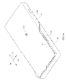
- FIGS. 1-3 show a bed for a hospital or other caregiving setting.
- the illustrations include reference axes 16, 18 indicating longitudinal and lateral directions respectively.
- the bed includes a mattress 20 having a top side 22 and a four-sided flank 24 comprised of left, right, foot end and head end flank sections 24L, 24R, 24F , 24H corresponding to the head, feet, left and right sides of a supine occupant of the bed.
- the mattress top side 22 and the four flanks 24 define mattress edges 30L, 30R , 30F, 30H .
- the mattress normally rests on a frame, not illustrated.
- the mattress hosts an occupant transfer device 34 which is in the form of a fitted bed sheet.
- the occupant transfer sheet has a top 36 for covering the top side 22 of the mattress.
- the top 36 is substantially spatially coextensive with the top side of the mattress.
- a skirt 38 having head, foot, left and right panels 38H, 38F, 38L, 38R extends from the top 36 to cover the mattress flanks.
- the top 36 of the sheet and the four skirt panels define sheet edges 32L, 32R , 32F, 32H .
- the portion of the skirt near the perimeter of the sheet is normally turned inward as seen in FIGS. 2 and 3 and tucked under the bottom of the mattress. Part or all of the sheet may be slightly elastic to ensure that the sheet fits snugly and securely on the mattress.
- the top 36 of the sheet has an occupant side 40 facing away from the mattress and a mattress side 42 facing toward the mattress.
- the skirt panels 38 each have an occupant side 44 and a mattress side 46 .
- Substantially all of the mattress side of the top 36 exhibits relatively low friction.
- the occupant side of at least the top exhibits relatively higher friction.
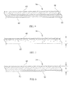
- the difference in friction can be achieved in any suitable manner. As seen in FIG. 4 the frictional properties of the occupant and mattress sides of the sheet may result from distinct high and low friction lamina 48, 50. Or, as seen in FIGS.
- the frictional properties may vary as a function of sheet thickness t such that the occupant side is of relatively high friction (as suggested by the irregular line used to depict the occupant side 40 ) and the mattress side is of relatively low friction (as suggested by the smooth line used to depict the mattress side 42 ).
- the varying density of the faceted symbols between sides 40 and 42 signifies a graduated change in frictional properties.
- the low friction properties of the mattress side 42 result from a low friction coating 52 .
- Two openings 54 are formed on both the left and right side panels of the skirt. Similar openings may also be present on the head and/or foot skirt panels. The openings serve as hand-hold openings so that a caregiver can grasp the sheet and slide it, and the occupant lying thereon, from a source bed to a destination bed.
- the margin 56 of each opening is reinforced to resist ripping.
- the left and right panel openings are approximately longitudinally equidistant from the estimated location CG of an occupant's center of gravity.
- one specific embodiment of the sheet is comprised of an outer layer made of cotton fabric 60 and a separate inner layer 62 made of rip-stop nylon.
- the outer layer has a top portion 64 for covering the top side of the mattress and a skirt portion 66 extending from the top portion and corresponding to the flank of the mattress.
- the outer layer has an exterior side 70 and an interior side 72 .
- the exterior side 70 of the outer layer is the occupant side 40, 44 of the fitted sheet and therefore exhibits high friction.
- the inner layer 62 has a top portion 78 substantially coextensive with the top portion 64 of the outer layer 60 .
- the inner layer also has an optional skirt portion 80 (included in FIG. 7 ; excluded in FIG. 8 ) extending from the top portion and corresponding to the mattress flank.
- the inner layer has an exterior side 82 and an interior side 84 .
- the exterior side 82 of the inner layer is the mattress side 42 , 46 of the fitted sheet.
- the exterior side of the inner layer top portion 78 exhibits relatively low friction. If the inner layer includes the optional skirt portion, the exterior side of the inner layer skirt portion 80 , is also preferably of low friction.
- the frictional properties of the inner layer may vary as a function of sheet thickness t such that the friction increases from the exterior side 82 toward the interior side 84 .
- the interior sides 72, 84 of the layers face each other and exhibit relatively low friction with respect to each other, allowing those interior sides to easily slide relative to each other.
- FIGS. 9-11 show how the inner layer 62 is stitched to the outer layer 60 near the layer edges.
- the stitching forms a continuous seam 90 along the head and foot ends of the sheet ( FIGS. 9 and 11 )
- the layers are spot stitched 92 to each other along the left and right sides ( FIGS. 10 and 11 ),
- the continuous seam 90 imparts strength to the inter-layer connection whereas the spot stitching allows the inner and outer layers to slip or move independently relative to each other both longitudinally and laterally.
- the location and extent of the continuous seam and the location of the spot stitching can be to the desired of strength and inter-layer slippage.
- the illustrated sheet employs a combination of continuous stitching and spot stitching, either way of stitching can be used exclusively.
- Openings 54 are formed by openings in the skirt portion left and right panels of the outer layer and companion openings in the skirt portion left and right of the inner layer. Similar openings may also be present on the head and/or foot skirt panels of the outer and inner layers.
- the margin of each outer layer opening its substantially continuously stitched, or otherwise attached, to the margin of its companion opening in the inner layer to form the opening margin 56 .
- inelastic bridge straps 98 having a grip loop 100 are secured to and extend from the occupant transfer sheet 34 instead of or in addition to openings 54 .
- FIG. 12 shows two possible types of attachment - a linear attachment nearer the head end of the sheet and a "delta" attachment nearer the foot end.
- Each strap has a working length W which is the distance from the left or right lateral edge 30L, 30R of the mattress (corresponding to the left and right edges 32L, 32R of the to the end 104 of the grip loop when a strap is extended substantially perpendicular to the longitudinal centerline 102 .
- the minimum working length equals about the width of a destination mattress reduced by the arm length of a fifth percentile female.
- Typical mattress widths in use in the United States are 36 inches (approximately 91.4cm.) for non-bariatric mattresses and 40 inches (approximately 101.5 cm) for bariatric mattresses.
- the arm length of a fifth percentile female can be determined from anthropometric data, such as the data compiled in " The Measure of Man and Women - Human Factors in Design” by Alvin R. Tilley, ISBN 0-471-09955-4 .
- FIGS. 13A and 13B show an alternative construction for a bridge strap.
- bridge strap 98 ' comprises an elastic member 112 , shown in its relaxed state, and an inelestic member 114 .
- the inelastic member includes folds 116 and is attached to the elastic member at locations 118 intermediate the folds.
- the bridge strap has a length W 1 smaller than its working length W . The smaller length allows the strap to be stored, when not in use, more conveniently than a strap of fixed length W .
- elastic member 112 stretches under the load while inelastic member 114 unfolds as seen in FIG. 13B .
- the inelastic member extends unfolded along the stretched length of the elastic member thus providing a second load path in parallel with the load path through the elastic member and preventing any further elongation of the elastic member,
- the strap is thus at its full working length W .
- the straps and sheet include mating fasteners, such as mating hook and loop fasteners 106 ( FIG. 12 ).
- mating fasteners such as mating hook and loop fasteners 106 ( FIG. 12 ).
- loop handles 108 secured to the mattress side of the skirt of the sheet instead of or in combination with the openings 54 and/or the bridge straps 98 .
- the handles When the handles are not in use they remain stored the and the sheet where they are easily accessible when needed but out of the way when not.
- a caregiver To use the loop handles rather than the hand-hold openings, a caregiver first turns up the skirt panel to gain access to the loop handles. If desired the loop handles could be installed on the occupant side of the sheet skirt instead of on the mattress side.
- the occupant transfer device doubles as a fitted sheet which is used on the mattress in lieu of a conventional fitted sheet.
- the caregiver staff need not retrieve a dedicated transfer apparatus from a remote location and position the apparatus under the occupant as a prelude to occupant transfer.
- a staff member will untuck the perimeter edge of the occupant transfer sheet, position a destination bed laterally along side the source bed occupied by the occupant, and deploy the bridge straps 98 by lying them across the top side of the destination mattress as shown.
- the caregiver positions himself along the lateral edge of the destination mattress remote from the source mattress. Because of the working length of the bridge straps, the free ends of the straps will be within easy of the caregiver.
- the caregiver can grasp the straps and pull the transfer sheet and the occupant onto the destination mattress without assuming a risky posture. If the caregiver can grasp the handhold openings or the loop handles to finish the transfer.
- the bridge straps may be dispensed with in favor of the openings 54 and/or loop handles 108 , but will lack the ergonomic benefits of a transfer sheet with bridge straps.
Landscapes
- Health & Medical Sciences (AREA)
- Business, Economics & Management (AREA)
- Critical Care (AREA)
- Emergency Management (AREA)
- Nursing (AREA)
- Life Sciences & Earth Sciences (AREA)
- Animal Behavior & Ethology (AREA)
- General Health & Medical Sciences (AREA)
- Public Health (AREA)
- Veterinary Medicine (AREA)
- Mattresses And Other Support Structures For Chairs And Beds (AREA)
- Invalid Beds And Related Equipment (AREA)
Abstract
Description
- The subject matter described herein to occupant transfer from one occupant support to another occupant support, and particularly to a fitted sheet for facilitating such transfer. One example application for the occupant transfer device is for transferring a patient from one bed to another.
- In hospitals and other caregiving settings it is sometimes necessary to transfer a patient from one bed (the source bed) to another (the destination bed). One or more caregivers transfer the patient by lifting and/or sliding the patient from the source bed to the destination bed. The physical effort required of the caregivers increases with increasing patient size and weight.
- Various devices are used to assist in patient transfers. These include reduced friction sheets or pads and powered surfaces that create an air cushion. These devices are not without merit, but also suffer from drawbacks. For example occupant transfer devices can be costly. In addition, occupant transfer devices are typically specialized devices dedicated to patient transfer rather than being intended for "full time" use on the bed. As a result, the device must be retrieved from a remote location and must be positioned under the patient before the transfer can take place. In addition, occupant transfer devices can be awkward to use, requiring the caregiver to bend at the waist in order to reach across the width of the destination bed and pull the transfer device, now bearing the patient's weight, onto the destination bed. The caregiver's posture along with the need to exert a substantial force increases the risk of caregiver injury.
- Accordingly, it is desirable to provide a patient transfer device that addresses at least some of the shortcomings of existing devices.
- There is disclosed an occupant transfer device for use on a host mattress having a top side and a flank is in the form of a fitted sheet. The device has a top for covering the top side of the mattress and a skirt extending from the top. The top and skirt each have an occupant side and a mattress side. Substantially all of the mattress side of the top exhibits relatively low friction; the occupant side of at least the top exhibits relatively higher friction.
- The invention will now be further described by way of example with reference to the accompanying drawings, in which:
-
FIG. 1 is a perspective view of a mattress and the occupant transfer device in the form of a fitted sheet viewed from above. -
FIG. 2 is a perspective view of a mattress and the occupant transfer sheet viewed from below. -
FIG. 3 is a perspective view of a corner of the occupant transfer sheet installed on a mattress and partially broken away to reveal the mattress. -
FIG. 4 is a partial side elevation view of the occupant transfer sheet showing distinct lamina forming high and low friction sides of the sheet. -
FIG. 5 is a partial side elevation view of the occupant transfer sheet with faceted symbols signifying graduated frictional properties through the thickness of the sheet. -
FIG. 6 is a partial side elevation view of the occupant transfer sheet with a coating to impart low friction to one side thereof. -
FIG. 7 is a view in the direction 7--7 ofFiG. 1 showing an embodiment of the occupant transfer sheet having a relatively high friction outer layer and a relatively low friction inner layer, each having a skirt portion. -
FIG. 8 is a view in thedirection 8--8 ofFiG. 1 showing an embodiment of the occupant transfer sheet a relatively high friction outer layer and a relatively low friction inner layer, only the outer layer having a skirt portion. -
FIG. 9 is an end elevation view of the embodiment ofFIG. 7 showing a continuous seam between the outer and inner layers along the head end panel of the sheet. -
FIG. 10 is a side elevation view of the embodiment ofFIG. 7 showing spot stitching between the outer and inner layers along the left side panel of the sheet. -
FIG. 11 is a plan view showing the continuous seam and spot stitching ofFIGS. 9 and10 . -
FIG. 12 is a perspective view of an occupant transfer sheet having bridge straps secured thereto -
FIGS. 13A and13B are perspective views showing a bridge strap featuring an elongation limited elastic construction,FIG. 13A showing the strap in a relaxed state andFIG. 13B showing the strap in a partially elongated state. -
FIG. 14 is a perspective view of a mattress with an occupant transfer sheet partially installed and a portion of the sheet turned up to reveal a loop handle. -
FIG. 15 is a perspective view showing the use of the bridge straps to transfer the occupant transfer sheet from a source mattress to a destination mattress. -
FIGS. 1-3 show a bed for a hospital or other caregiving setting. The illustrations includereference axes mattress 20 having atop side 22 and a four-sided flank 24 comprised of left, right, foot end and headend flank sections top side 22 and the fourflanks 24 definemattress edges occupant transfer device 34 which is in the form of a fitted bed sheet. - The occupant transfer sheet has a
top 36 for covering thetop side 22 of the mattress. When the sheet is installed on the mattress thetop 36 is substantially spatially coextensive with the top side of the mattress. Askirt 38 having head, foot, left andright panels top 36 to cover the mattress flanks. Thetop 36 of the sheet and the four skirt panels definesheet edges FIGS. 2 and3 and tucked under the bottom of the mattress. Part or all of the sheet may be slightly elastic to ensure that the sheet fits snugly and securely on the mattress. - The
top 36 of the sheet has anoccupant side 40 facing away from the mattress and amattress side 42 facing toward the mattress. Likewise, theskirt panels 38 each have anoccupant side 44 and amattress side 46. Substantially all of the mattress side of thetop 36 exhibits relatively low friction. The occupant side of at least the top exhibits relatively higher friction. The difference in friction can be achieved in any suitable manner. As seen inFIG. 4 the frictional properties of the occupant and mattress sides of the sheet may result from distinct high andlow friction lamina FIGS. 5 and 6 , the frictional properties may vary as a function of sheet thickness t such that the occupant side is of relatively high friction (as suggested by the irregular line used to depict the occupant side 40) and the mattress side is of relatively low friction (as suggested by the smooth line used to depict the mattress side 42). InFIG. 5 the varying density of the faceted symbols betweensides FIG. 6 the low friction properties of themattress side 42 result from alow friction coating 52. - Two
openings 54 are formed on both the left and right side panels of the skirt. Similar openings may also be present on the head and/or foot skirt panels. The openings serve as hand-hold openings so that a caregiver can grasp the sheet and slide it, and the occupant lying thereon, from a source bed to a destination bed. Themargin 56 of each opening is reinforced to resist ripping. The left and right panel openings are approximately longitudinally equidistant from the estimated location CG of an occupant's center of gravity. - As seen in
FIGS. 7 and 8 one specific embodiment of the sheet is comprised of an outer layer made ofcotton fabric 60 and a separateinner layer 62 made of rip-stop nylon. The outer layer has atop portion 64 for covering the top side of the mattress and askirt portion 66 extending from the top portion and corresponding to the flank of the mattress. The outer layer has an exterior side 70 and aninterior side 72. The exterior side 70 of the outer layer is theoccupant side - The
inner layer 62 has atop portion 78 substantially coextensive with thetop portion 64 of theouter layer 60. The inner layer also has an optional skirt portion 80 (included inFIG. 7 ; excluded inFIG. 8 ) extending from the top portion and corresponding to the mattress flank. The inner layer has an exterior side 82 and aninterior side 84. The exterior side 82 of the inner layer is themattress side top portion 78, exhibits relatively low friction. If the inner layer includes the optional skirt portion, the exterior side of the innerlayer skirt portion 80, is also preferably of low friction. The frictional properties of the inner layer may vary as a function of sheet thickness t such that the friction increases from the exterior side 82 toward theinterior side 84. - The interior sides 72, 84 of the layers face each other and exhibit relatively low friction with respect to each other, allowing those interior sides to easily slide relative to each other.
-
FIGS. 9-11 show how theinner layer 62 is stitched to theouter layer 60 near the layer edges. The stitching forms acontinuous seam 90 along the head and foot ends of the sheet (FIGS. 9 and11 ) The layers are spot stitched 92 to each other along the left and right sides (FIGS. 10 and11 ), Thecontinuous seam 90 imparts strength to the inter-layer connection whereas the spot stitching allows the inner and outer layers to slip or move independently relative to each other both longitudinally and laterally. The location and extent of the continuous seam and the location of the spot stitching can be to the desired of strength and inter-layer slippage. Although the illustrated sheet employs a combination of continuous stitching and spot stitching, either way of stitching can be used exclusively. -
Openings 54 are formed by openings in the skirt portion left and right panels of the outer layer and companion openings in the skirt portion left and right of the inner layer. Similar openings may also be present on the head and/or foot skirt panels of the outer and inner layers. The margin of each outer layer opening its substantially continuously stitched, or otherwise attached, to the margin of its companion opening in the inner layer to form theopening margin 56. - Referring to
FIG. 12 , inelastic bridge straps 98 having agrip loop 100 are secured to and extend from theoccupant transfer sheet 34 instead of or in addition toopenings 54.FIG. 12 shows two possible types of attachment - a linear attachment nearer the head end of the sheet and a "delta" attachment nearer the foot end. Each strap has a working length W which is the distance from the left or rightlateral edge right edges end 104 of the grip loop when a strap is extended substantially perpendicular to thelongitudinal centerline 102. The minimum working length equals about the width of a destination mattress reduced by the arm length of a fifth percentile female. Typical mattress widths in use in the United States are 36 inches (approximately 91.4cm.) for non-bariatric mattresses and 40 inches (approximately 101.5 cm) for bariatric mattresses. The arm length of a fifth percentile female can be determined from anthropometric data, such as the data compiled in "The Measure of Man and Woman - Human Factors in Design" by Alvin R. Tilley, ISBN 0-471-09955-4. -
FIGS. 13A and13B show an alternative construction for a bridge strap. Referring first toFIG. 13A bridge strap 98' comprises anelastic member 112, shown in its relaxed state, and aninelestic member 114. The inelastic member includesfolds 116 and is attached to the elastic member atlocations 118 intermediate the folds. When not in use, the bridge strap has a length W1 smaller than its working length W. The smaller length allows the strap to be stored, when not in use, more conveniently than a strap of fixed length W. When a caregiver applies a force F to the strap,elastic member 112 stretches under the load whileinelastic member 114 unfolds as seen inFIG. 13B . In the limit, the inelastic member extends unfolded along the stretched length of the elastic member thus providing a second load path in parallel with the load path through the elastic member and preventing any further elongation of the elastic member, The strap is thus at its full working length W. - It may be desirable to provide a way to secure the straps between the mattress flanks 24 and the mattress sides 48 of the
sheet skirt 38 when the straps are not in use. To this end the straps and sheet include mating fasteners, such as mating hook and loop fasteners 106 (FIG. 12 ). When the straps are not in use they may be stored securely but accessibly in the space between the mattress flank and the skirt portion of the sheet with the hook and loop fasteners keeping the straps in place. - Referring to
FIG. 14 it may also be desirable to include loop handles 108 secured to the mattress side of the skirt of the sheet instead of or in combination with theopenings 54 and/or the bridge straps 98. When the handles are not in use they remain stored the and the sheet where they are easily accessible when needed but out of the way when not. To use the loop handles rather than the hand-hold openings, a caregiver first turns up the skirt panel to gain access to the loop handles. If desired the loop handles could be installed on the occupant side of the sheet skirt instead of on the mattress side. - The occupant transfer device doubles as a fitted sheet which is used on the mattress in lieu of a conventional fitted sheet. As a result the caregiver staff need not retrieve a dedicated transfer apparatus from a remote location and position the apparatus under the occupant as a prelude to occupant transfer. Instead, as seen in
FIG. 15 , it is envisioned that a staff member will untuck the perimeter edge of the occupant transfer sheet, position a destination bed laterally along side the source bed occupied by the occupant, and deploy the bridge straps 98 by lying them across the top side of the destination mattress as shown. The caregiver positions himself along the lateral edge of the destination mattress remote from the source mattress. Because of the working length of the bridge straps, the free ends of the straps will be within easy of the caregiver. Accordingly, the caregiver can grasp the straps and pull the transfer sheet and the occupant onto the destination mattress without assuming a risky posture. If the caregiver can grasp the handhold openings or the loop handles to finish the transfer. As already noted the bridge straps may be dispensed with in favor of theopenings 54 and/or loop handles 108, but will lack the ergonomic benefits of a transfer sheet with bridge straps. - Although this disclosure refers to specific embodiments, it will be understood by those skilled in the art that various changes in form and detail may be made.
Claims (10)
- An occupant transfer device for use on a host mattress having a top side and a flank, the device comprising a fitted sheet having a top for covering the top side of the mattress and a skirt extending from the top, the top and skirt each having an inner layer having a top portion for covering the top side of the mattress, the inner layer having an exterior side and an interior side, the exterior side of the inner layer is a mattress side of the fitted sheet, and an outer layer having a top portion substantially with the top portion of the inner layer, the outer layer also having an exterior side and an interior side, wherein the exterior side of the inner layer is an occupant side of the fitted sheet, substantially all of the top portion of the inner layer exhibiting relatively low friction, and the top portion of the outer layer exhibiting relatively higher friction.
- The of claim 1 wherein the exterior side of the skirt portion of the inner layer also exhibits relatively lower friction.
- The device of either claim 1 or claim 2 wherein the relatively low friction results from a coating.
- The device of any preceding claim including aligned openings in the skirt portion of the outer layer and the skirt portion of the inner layer, each opening having a margin, the margins being substantially continuously attached to each other.
- The device of any preceding claim including a bridge strap secured to the sheet, the bridge strap having a working length of approximately at least the width of a destination mattress minus the arm length of a fifth percentile female.
- The of claim 5 wherein the destination mattress is a bariatric mattress.
- The device of either claim 5 or claim 6 wherein the bridge strap is storable between the mattress and the skirt.
- The device of any preceding claim including a loop handle secured to the side of the sheet.
- The occupant transfer device of any preceding claim wherein the inner layer has an inner layer edge, the outer layer has an outer layer edge, the layer edges being joined to each other over at least part of their respective lengths with a continuous seam and over any remainder of their respective lengths with spot connections.
- The occupant transfer device of claim 9 wherein the layer edges are joined to each other the continuous seam along laterally extending portions thereof and are joined to each other with the spot connections along longitudinally extending portions thereof.
Applications Claiming Priority (1)
| Application Number | Priority Date | Filing Date | Title |
|---|---|---|---|
| US12/570,673 US7849533B1 (en) | 2009-09-30 | 2009-09-30 | Occupant transfer sheet |
Publications (2)
| Publication Number | Publication Date |
|---|---|
| EP2305199A2 true EP2305199A2 (en) | 2011-04-06 |
| EP2305199A3 EP2305199A3 (en) | 2011-07-06 |
Family
ID=43302994
Family Applications (1)
| Application Number | Title | Priority Date | Filing Date |
|---|---|---|---|
| EP10178432A Withdrawn EP2305199A3 (en) | 2009-09-30 | 2010-09-22 | Occupant transfer sheet |
Country Status (2)
| Country | Link |
|---|---|
| US (1) | US7849533B1 (en) |
| EP (1) | EP2305199A3 (en) |
Cited By (1)
| Publication number | Priority date | Publication date | Assignee | Title |
|---|---|---|---|---|
| WO2015101631A1 (en) | 2013-12-31 | 2015-07-09 | Sense Textile B.V. | Stretchable textile stay and transfer sheet |
Families Citing this family (25)
| Publication number | Priority date | Publication date | Assignee | Title |
|---|---|---|---|---|
| WO2008109099A1 (en) * | 2007-03-05 | 2008-09-12 | Paper-Pak Industries | Disposable transporter |
| US20110265268A1 (en) * | 2010-05-03 | 2011-11-03 | William John Scarleski | Passive mattress spinner |
| US8006331B1 (en) | 2010-05-03 | 2011-08-30 | William J. Scarleski | Active mattress spinner |
| US11470981B2 (en) | 2010-05-03 | 2022-10-18 | Levitation Sciences Llc | Four-in-one mattress management system |
| US9021630B2 (en) | 2010-05-03 | 2015-05-05 | Levitation Sciences Llc | Bedmaker |
| US20210321786A1 (en) * | 2010-05-03 | 2021-10-21 | Levitation Sciences Llc | Single Cover Passive Mattress Spinner |
| US10327562B2 (en) | 2010-05-03 | 2019-06-25 | Levitation Sciences Llc | Four-in-one mattress management system |
| US10123630B2 (en) * | 2010-05-03 | 2018-11-13 | Levitation Sciences Llc | Single cover passive mattress spinner |
| US9414977B2 (en) * | 2011-01-26 | 2016-08-16 | Sage Products, Llc | Apparatus and system for turning and positioning a patient |
| US8789533B2 (en) | 2011-01-26 | 2014-07-29 | Sage Products, Llc | Method for turning and positioning a patient |
| EP2900106A4 (en) * | 2012-09-27 | 2016-10-12 | Levitation Sciences Llc | Single cover passive mattress spinner |
| US9814324B2 (en) | 2013-10-04 | 2017-11-14 | Levitation Sciences Llc | Passive mattress encasement |
| US20170340133A1 (en) | 2013-10-04 | 2017-11-30 | Levitation Sciences Llc | Passive mattress encasement |
| US9596946B2 (en) * | 2013-10-04 | 2017-03-21 | Levitation Sciences Llc | Active mattress encasement |
| US20170340132A1 (en) | 2013-10-04 | 2017-11-30 | Levitation Sciences Llc | Active mattress encasement |
| USD748932S1 (en) * | 2014-03-03 | 2016-02-09 | Elaine Snider Puricelli | Two-layer towel having a corrugated design |
| US9693919B2 (en) * | 2014-10-07 | 2017-07-04 | Medline Industries, Inc. | Patient transport device with strap concealment apparatus and corresponding methods |
| WO2016081781A2 (en) * | 2014-11-19 | 2016-05-26 | Science Medical, LLC | Disposable therapeutic bed linen |
| US20160184154A1 (en) * | 2014-12-31 | 2016-06-30 | Stryker Corporation | Support surface system |
| US9820905B2 (en) | 2015-09-01 | 2017-11-21 | Science Medical, LLC | Bed sheet lift system |
| US20180353361A1 (en) * | 2015-11-24 | 2018-12-13 | Lateral Prep, LLC | Supine patient transfer package |
| US10828216B2 (en) | 2017-03-03 | 2020-11-10 | Medline Industries, Inc. | Inflatable patient repositioning sheet |
| US10772778B2 (en) * | 2017-04-25 | 2020-09-15 | Medline Industries, Inc. | Patient repositioning sheet and sling |
| US11331235B2 (en) | 2019-09-13 | 2022-05-17 | Medline Industries, Lp | Patient repositioning sheet, system, and method |
| US20250127307A1 (en) * | 2023-10-20 | 2025-04-24 | Hill-Rom Services, Inc. | Attachment system for patient support apparatus |
Citations (1)
| Publication number | Priority date | Publication date | Assignee | Title |
|---|---|---|---|---|
| US3829914A (en) | 1972-12-26 | 1974-08-20 | C Treat | Patient positioning device |
Family Cites Families (17)
| Publication number | Priority date | Publication date | Assignee | Title |
|---|---|---|---|---|
| US3769642A (en) * | 1971-03-29 | 1973-11-06 | B Warman | Patient transfer method and apparatus |
| US4051565A (en) * | 1976-07-26 | 1977-10-04 | Trygve Berge | Mat conveyor |
| US4651370A (en) * | 1985-04-04 | 1987-03-24 | Perfect Fit Industries, Inc. | One-piece fitted sheet and mattress pad |
| US4747170A (en) | 1986-08-15 | 1988-05-31 | Knouse Bobby W | Patient mover |
| US5138731A (en) * | 1991-10-11 | 1992-08-18 | Beverly A. Heron | Person movement assistance appliance |
| US5249320A (en) * | 1991-11-12 | 1993-10-05 | Moretz Herbert L | Moisture-managing bed pad and bed sheet |
| AU6256694A (en) | 1993-03-09 | 1994-09-26 | Inter Care A/S | A sheet, and an assembly comprising a sheet and a mat conveyor |
| US5329655A (en) | 1993-05-18 | 1994-07-19 | Dean Garner | Slidable hospital sheet for turning patients |
| US5465441A (en) * | 1994-07-25 | 1995-11-14 | Chun; Bongsoo | Slideable seating member |
| US5615425A (en) * | 1995-10-06 | 1997-04-01 | Corente; Joseph N. | Fitted sheet for use as a disposable stretcher/gurney linen |
| US5742958A (en) | 1996-03-28 | 1998-04-28 | Solazzo; Anthony | Inflatable patient transfer roller mattress |
| US5860174A (en) | 1996-12-03 | 1999-01-19 | Hausted, Inc. | Patient transfer mattress system |
| US5920929A (en) * | 1997-12-01 | 1999-07-13 | Henwood Corporation | Immobile-patient transfer device |
| US6381778B1 (en) * | 2000-01-11 | 2002-05-07 | Jennifer R. Peterson | Fitted sheet |
| US20070000048A1 (en) | 2004-12-16 | 2007-01-04 | Davis David T | Pneumatic lift and method for transferring an invalid patient |
| US7904979B2 (en) | 2006-02-06 | 2011-03-15 | Hill-Rom Services, Inc. | Mattress with patient transport apparatus incorporated therein |
| US7650654B2 (en) | 2007-03-05 | 2010-01-26 | Stryker Corporation | Transfer device |
-
2009
- 2009-09-30 US US12/570,673 patent/US7849533B1/en not_active Expired - Fee Related
-
2010
- 2010-09-22 EP EP10178432A patent/EP2305199A3/en not_active Withdrawn
Patent Citations (1)
| Publication number | Priority date | Publication date | Assignee | Title |
|---|---|---|---|---|
| US3829914A (en) | 1972-12-26 | 1974-08-20 | C Treat | Patient positioning device |
Cited By (2)
| Publication number | Priority date | Publication date | Assignee | Title |
|---|---|---|---|---|
| WO2015101631A1 (en) | 2013-12-31 | 2015-07-09 | Sense Textile B.V. | Stretchable textile stay and transfer sheet |
| EP2921579A1 (en) | 2013-12-31 | 2015-09-23 | Sense Textile B.V. | Stretchable textile stay and transfer sheet |
Also Published As
| Publication number | Publication date |
|---|---|
| EP2305199A3 (en) | 2011-07-06 |
| US7849533B1 (en) | 2010-12-14 |
Similar Documents
| Publication | Publication Date | Title |
|---|---|---|
| US7849533B1 (en) | Occupant transfer sheet | |
| US7975330B2 (en) | Occupant transfer topper | |
| US9445963B2 (en) | Patient transfer system | |
| US7904979B2 (en) | Mattress with patient transport apparatus incorporated therein | |
| US8789533B2 (en) | Method for turning and positioning a patient | |
| US5901388A (en) | Mono-pull drawsheet | |
| JP5425625B2 (en) | Rescue and transport equipment | |
| US5729850A (en) | Stretcher | |
| US7240384B2 (en) | Method of repositioning immobile patient in bed using patient positioning aid | |
| US5920929A (en) | Immobile-patient transfer device | |
| US20120186012A1 (en) | Apparatus and system for turning and positioning a patient | |
| US20050246834A1 (en) | Patient transfer mattress having side pull straps | |
| JPWO2008013239A1 (en) | Mattress cover for transport during disasters | |
| CA2324197C (en) | Sheet for stretcher/gurney | |
| EP2667836B1 (en) | Apparatus, system, and method for turning and positioning a patient | |
| US3364506A (en) | Draw sheet stretcher | |
| US7836528B2 (en) | Differential traction bedding | |
| US10307312B2 (en) | Gurney protective cover | |
| KR20200012230A (en) | A body straighter | |
| CN106999331A (en) | Patient Lifting Equipment | |
| JP2008212186A (en) | Variable slide board for care | |
| JP4147558B2 (en) | Nursing care mat | |
| CN206167246U (en) | Novel prevent sheet that glides | |
| US5787526A (en) | Bed with removable passive restraining device for a user of the bed | |
| GB2338700A (en) | Patient transfer aid |
Legal Events
| Date | Code | Title | Description |
|---|---|---|---|
| PUAI | Public reference made under article 153(3) epc to a published international application that has entered the european phase |
Free format text: ORIGINAL CODE: 0009012 |
|
| AK | Designated contracting states |
Kind code of ref document: A2 Designated state(s): AL AT BE BG CH CY CZ DE DK EE ES FI FR GB GR HR HU IE IS IT LI LT LU LV MC MK MT NL NO PL PT RO SE SI SK SM TR |
|
| AX | Request for extension of the european patent |
Extension state: BA ME RS |
|
| PUAL | Search report despatched |
Free format text: ORIGINAL CODE: 0009013 |
|
| AK | Designated contracting states |
Kind code of ref document: A3 Designated state(s): AL AT BE BG CH CY CZ DE DK EE ES FI FR GB GR HR HU IE IS IT LI LT LU LV MC MK MT NL NO PL PT RO SE SI SK SM TR |
|
| AX | Request for extension of the european patent |
Extension state: BA ME RS |
|
| 17P | Request for examination filed |
Effective date: 20120106 |
|
| 17Q | First examination report despatched |
Effective date: 20120412 |
|
| RAP1 | Party data changed (applicant data changed or rights of an application transferred) |
Owner name: HILL-ROM SERVICES, INC. |
|
| RIC1 | Information provided on ipc code assigned before grant |
Ipc: A61G 7/10 20060101ALI20130122BHEP Ipc: A47G 9/02 20060101ALI20130122BHEP Ipc: A61G 7/05 20060101AFI20130122BHEP |
|
| GRAP | Despatch of communication of intention to grant a patent |
Free format text: ORIGINAL CODE: EPIDOSNIGR1 |
|
| STAA | Information on the status of an ep patent application or granted ep patent |
Free format text: STATUS: THE APPLICATION IS DEEMED TO BE WITHDRAWN |
|
| 18D | Application deemed to be withdrawn |
Effective date: 20130723 |