EP2305132A1 - Method of suture identification and mesh marking for orienting and locating a mesh during hernia repair - Google Patents
Method of suture identification and mesh marking for orienting and locating a mesh during hernia repair Download PDFInfo
- Publication number
- EP2305132A1 EP2305132A1 EP20100251733 EP10251733A EP2305132A1 EP 2305132 A1 EP2305132 A1 EP 2305132A1 EP 20100251733 EP20100251733 EP 20100251733 EP 10251733 A EP10251733 A EP 10251733A EP 2305132 A1 EP2305132 A1 EP 2305132A1
- Authority
- EP
- European Patent Office
- Prior art keywords
- mesh
- suture
- mesh material
- visual indicators
- kit according
- Prior art date
- Legal status (The legal status is an assumption and is not a legal conclusion. Google has not performed a legal analysis and makes no representation as to the accuracy of the status listed.)
- Granted
Links
- 238000000034 method Methods 0.000 title claims description 29
- 230000008439 repair process Effects 0.000 title claims description 9
- 206010019909 Hernia Diseases 0.000 title claims description 4
- 239000000463 material Substances 0.000 claims abstract description 52
- 230000000007 visual effect Effects 0.000 claims abstract description 35
- 244000309464 bull Species 0.000 claims description 24
- 239000003086 colorant Substances 0.000 claims description 9
- 230000008569 process Effects 0.000 claims description 7
- 229920000642 polymer Polymers 0.000 claims description 2
- 239000012636 effector Substances 0.000 claims 1
- 210000001519 tissue Anatomy 0.000 description 15
- 239000003356 suture material Substances 0.000 description 13
- 230000008901 benefit Effects 0.000 description 7
- 238000012978 minimally invasive surgical procedure Methods 0.000 description 7
- 238000001356 surgical procedure Methods 0.000 description 7
- 230000000712 assembly Effects 0.000 description 4
- 238000000429 assembly Methods 0.000 description 4
- 238000013461 design Methods 0.000 description 4
- 239000000853 adhesive Substances 0.000 description 3
- 230000001070 adhesive effect Effects 0.000 description 3
- 238000000576 coating method Methods 0.000 description 3
- 239000001993 wax Substances 0.000 description 3
- 238000004040 coloring Methods 0.000 description 2
- 238000010304 firing Methods 0.000 description 2
- 238000004519 manufacturing process Methods 0.000 description 2
- 238000012986 modification Methods 0.000 description 2
- 230000004048 modification Effects 0.000 description 2
- 229920001296 polysiloxane Polymers 0.000 description 2
- 239000001856 Ethyl cellulose Substances 0.000 description 1
- ZZSNKZQZMQGXPY-UHFFFAOYSA-N Ethyl cellulose Chemical compound CCOCC1OC(OC)C(OCC)C(OCC)C1OC1C(O)C(O)C(OC)C(CO)O1 ZZSNKZQZMQGXPY-UHFFFAOYSA-N 0.000 description 1
- 229920006360 Hostaflon Polymers 0.000 description 1
- 239000004698 Polyethylene Substances 0.000 description 1
- 239000004809 Teflon Substances 0.000 description 1
- 229920006362 Teflon® Polymers 0.000 description 1
- 238000005299 abrasion Methods 0.000 description 1
- 239000002253 acid Substances 0.000 description 1
- 238000004873 anchoring Methods 0.000 description 1
- 235000013871 bee wax Nutrition 0.000 description 1
- 239000012166 beeswax Substances 0.000 description 1
- 210000004204 blood vessel Anatomy 0.000 description 1
- 239000003054 catalyst Substances 0.000 description 1
- 239000011248 coating agent Substances 0.000 description 1
- 230000007547 defect Effects 0.000 description 1
- 238000002405 diagnostic procedure Methods 0.000 description 1
- 238000002674 endoscopic surgery Methods 0.000 description 1
- 238000005516 engineering process Methods 0.000 description 1
- 229920001249 ethyl cellulose Polymers 0.000 description 1
- 235000019325 ethyl cellulose Nutrition 0.000 description 1
- 239000012530 fluid Substances 0.000 description 1
- 230000006870 function Effects 0.000 description 1
- 239000003292 glue Substances 0.000 description 1
- 230000035876 healing Effects 0.000 description 1
- 238000003780 insertion Methods 0.000 description 1
- 230000037431 insertion Effects 0.000 description 1
- 238000012977 invasive surgical procedure Methods 0.000 description 1
- 238000002357 laparoscopic surgery Methods 0.000 description 1
- 239000002184 metal Substances 0.000 description 1
- 239000000178 monomer Substances 0.000 description 1
- 238000007645 offset printing Methods 0.000 description 1
- 238000002355 open surgical procedure Methods 0.000 description 1
- 238000007649 pad printing Methods 0.000 description 1
- 239000012169 petroleum derived wax Substances 0.000 description 1
- 235000019381 petroleum wax Nutrition 0.000 description 1
- -1 polyethylene Polymers 0.000 description 1
- 229920000573 polyethylene Polymers 0.000 description 1
- 229920001343 polytetrafluoroethylene Polymers 0.000 description 1
- 239000004810 polytetrafluoroethylene Substances 0.000 description 1
- 230000009467 reduction Effects 0.000 description 1
- 238000009958 sewing Methods 0.000 description 1
- 229920002379 silicone rubber Polymers 0.000 description 1
- 210000003491 skin Anatomy 0.000 description 1
- 210000004872 soft tissue Anatomy 0.000 description 1
- BFKJFAAPBSQJPD-UHFFFAOYSA-N tetrafluoroethene Chemical compound FC(F)=C(F)F BFKJFAAPBSQJPD-UHFFFAOYSA-N 0.000 description 1
- 238000002560 therapeutic procedure Methods 0.000 description 1
- 230000017423 tissue regeneration Effects 0.000 description 1
- 210000001835 viscera Anatomy 0.000 description 1
- 238000012800 visualization Methods 0.000 description 1
- 238000009941 weaving Methods 0.000 description 1
Images



Classifications
-
- A—HUMAN NECESSITIES
- A61—MEDICAL OR VETERINARY SCIENCE; HYGIENE
- A61B—DIAGNOSIS; SURGERY; IDENTIFICATION
- A61B17/00—Surgical instruments, devices or methods
- A61B17/04—Surgical instruments, devices or methods for suturing wounds; Holders or packages for needles or suture materials
- A61B17/06—Needles ; Sutures; Needle-suture combinations; Holders or packages for needles or suture materials
- A61B17/06166—Sutures
-
- A—HUMAN NECESSITIES
- A61—MEDICAL OR VETERINARY SCIENCE; HYGIENE
- A61B—DIAGNOSIS; SURGERY; IDENTIFICATION
- A61B90/00—Instruments, implements or accessories specially adapted for surgery or diagnosis and not covered by any of the groups A61B1/00 - A61B50/00, e.g. for luxation treatment or for protecting wound edges
- A61B90/90—Identification means for patients or instruments, e.g. tags
- A61B90/94—Identification means for patients or instruments, e.g. tags coded with symbols, e.g. text
-
- A—HUMAN NECESSITIES
- A61—MEDICAL OR VETERINARY SCIENCE; HYGIENE
- A61F—FILTERS IMPLANTABLE INTO BLOOD VESSELS; PROSTHESES; DEVICES PROVIDING PATENCY TO, OR PREVENTING COLLAPSING OF, TUBULAR STRUCTURES OF THE BODY, e.g. STENTS; ORTHOPAEDIC, NURSING OR CONTRACEPTIVE DEVICES; FOMENTATION; TREATMENT OR PROTECTION OF EYES OR EARS; BANDAGES, DRESSINGS OR ABSORBENT PADS; FIRST-AID KITS
- A61F2/00—Filters implantable into blood vessels; Prostheses, i.e. artificial substitutes or replacements for parts of the body; Appliances for connecting them with the body; Devices providing patency to, or preventing collapsing of, tubular structures of the body, e.g. stents
- A61F2/0063—Implantable repair or support meshes, e.g. hernia meshes
-
- A—HUMAN NECESSITIES
- A61—MEDICAL OR VETERINARY SCIENCE; HYGIENE
- A61B—DIAGNOSIS; SURGERY; IDENTIFICATION
- A61B17/00—Surgical instruments, devices or methods
- A61B17/0057—Implements for plugging an opening in the wall of a hollow or tubular organ, e.g. for sealing a vessel puncture or closing a cardiac septal defect
- A61B2017/00646—Type of implements
- A61B2017/00659—Type of implements located only on one side of the opening
-
- A—HUMAN NECESSITIES
- A61—MEDICAL OR VETERINARY SCIENCE; HYGIENE
- A61B—DIAGNOSIS; SURGERY; IDENTIFICATION
- A61B90/00—Instruments, implements or accessories specially adapted for surgery or diagnosis and not covered by any of the groups A61B1/00 - A61B50/00, e.g. for luxation treatment or for protecting wound edges
- A61B90/39—Markers, e.g. radio-opaque or breast lesions markers
- A61B2090/3937—Visible markers
-
- A—HUMAN NECESSITIES
- A61—MEDICAL OR VETERINARY SCIENCE; HYGIENE
- A61F—FILTERS IMPLANTABLE INTO BLOOD VESSELS; PROSTHESES; DEVICES PROVIDING PATENCY TO, OR PREVENTING COLLAPSING OF, TUBULAR STRUCTURES OF THE BODY, e.g. STENTS; ORTHOPAEDIC, NURSING OR CONTRACEPTIVE DEVICES; FOMENTATION; TREATMENT OR PROTECTION OF EYES OR EARS; BANDAGES, DRESSINGS OR ABSORBENT PADS; FIRST-AID KITS
- A61F2/00—Filters implantable into blood vessels; Prostheses, i.e. artificial substitutes or replacements for parts of the body; Appliances for connecting them with the body; Devices providing patency to, or preventing collapsing of, tubular structures of the body, e.g. stents
- A61F2/02—Prostheses implantable into the body
- A61F2/30—Joints
- A61F2002/30001—Additional features of subject-matter classified in A61F2/28, A61F2/30 and subgroups thereof
- A61F2002/30316—The prosthesis having different structural features at different locations within the same prosthesis; Connections between prosthetic parts; Special structural features of bone or joint prostheses not otherwise provided for
- A61F2002/30535—Special structural features of bone or joint prostheses not otherwise provided for
- A61F2002/30617—Visible markings for adjusting, locating or measuring
-
- A—HUMAN NECESSITIES
- A61—MEDICAL OR VETERINARY SCIENCE; HYGIENE
- A61F—FILTERS IMPLANTABLE INTO BLOOD VESSELS; PROSTHESES; DEVICES PROVIDING PATENCY TO, OR PREVENTING COLLAPSING OF, TUBULAR STRUCTURES OF THE BODY, e.g. STENTS; ORTHOPAEDIC, NURSING OR CONTRACEPTIVE DEVICES; FOMENTATION; TREATMENT OR PROTECTION OF EYES OR EARS; BANDAGES, DRESSINGS OR ABSORBENT PADS; FIRST-AID KITS
- A61F2250/00—Special features of prostheses classified in groups A61F2/00 - A61F2/26 or A61F2/82 or A61F9/00 or A61F11/00 or subgroups thereof
- A61F2250/0058—Additional features; Implant or prostheses properties not otherwise provided for
- A61F2250/0096—Markers and sensors for detecting a position or changes of a position of an implant, e.g. RF sensors, ultrasound markers
- A61F2250/0097—Visible markings, e.g. indicia
Definitions
- the present disclosure relates to mesh and suture kits. Particularly, the present disclosure relates to sutures and mesh material each having one or more markings for identifying the orientation of the mesh relative to tissue of a subject.
- suture material is commonly used to repair openings in skin, internal organs, blood vessels, and a variety of other tissues of the human body. Conventionally, suturing of human tissue occurs during open surgery or minimally invasive surgical procedures.
- a surgeon performs diagnostic and therapeutic procedures at the surgical site through a natural body aperture or through one or more small incisions, using instruments specially designed for this purpose.
- Problems encountered by a surgeon in such minimally invasive surgical procedures include identifying which suture strands belong in a pair and which belong to a specific corner of a mesh material.
- suturing procedures can be particularly challenging in minimally invasive surgical procedures. For example, it can be difficult for a surgeon to determine various properties of the suture material being used, such as the orientation of the mesh and the distinction between the various sutures.
- suture management can present particular challenges for a surgeon, particularly since such procedures are often arthroscopically performed using remote visualization. The surgeon must be able to identify which suture ends are associated with each suture anchor and with each other, to properly execute a repair and to ensure that a suture is not accidentally demounted from an anchor. In arthroscopic repair procedures, suture management can be particularly difficult because the visibility of the anchors at the surgical site, and of the sutures associated with the anchors, may be very limited. Moreover, the presence of a large number of suture strands extending from a surgical site can result in physical and visual clutter, further increasing the difficulty of the surgical procedure for the surgeon, and presenting a risk of tangling sutures.
- the present disclosure is directed to a suture kit including a plurality of flexible strands of suture, each of the strands of suture having one or more suture markings indicative of a suture orientation and a mesh material configured to enable the strands of suture to be passed therethrough, wherein at least one quadrant/section of the mesh material having one or more mesh markings is indicative of a mesh material orientation.
- the one or more suture markings include visual indicators and the one or more mesh markings include visual indicators, the suture visual indicators correspond to the mesh visual indicators for indicating correct orientation of the mesh material with respect to tissue of a subject.
- a method for suturing including providing a suture kit having a plurality of flexible strands of suture and a mesh material, introducing the mesh material into a surgical site, and orientating the mesh material in relation to the surgical site via one or more mesh visual indicators.
- the next step includes correlating the plurality of flexible strands of suture having one or more suture markings to corresponding mesh markings. Additionally, the fastening of the mesh material to the surgical site via the plurality of flexible strands is performed.
- a surgical kit assembly including four sutures, each of the four sutures having a different suture color and a mesh layer having four patches, each of the four patches having a different patch color.
- the suture colors on the sutures correspond to the patch colors on the mesh layer, the mesh layer further including lettering and a bull's eye stamp on the anterior surface of the mesh layer to indicate an orientation of the mesh layer.
- the mesh material includes lettering placed on a top surface or an anterior surface of the mesh material, preferably the lettering on the top surface or the anterior surface of the material is "TOP.”
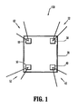
- FIG. 1 is a perspective view of a plurality of different colored sutures in cooperation with a pre-marked mesh, in accordance with the present disclosure
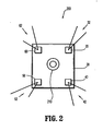
- FIG. 2 is a perspective view of a plurality of different colored sutures in cooperation with a pre-marked mesh having a bull's eye stamp on the anterior side of the mesh, in accordance with the present disclosure
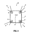
- FIG. 3 is a perspective view of a plurality of different colored sutures in cooperation with a pre-marked mesh having lettering across the anterior side of the mesh, in accordance with the present disclosure
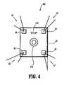
- FIG. 4 is a perspective view of a plurality of different colored sutures in cooperation with a pre-marked mesh having both a bull's eye stamp and lettering across the anterior side of the mesh, in accordance with the present disclosure
- FIG. 5 is a perspective view of a plurality of different colored sutures in cooperation with a pre-marked mesh having both lettering and arrow-like indicia across the anterior side of the mesh, in accordance with the present disclosure
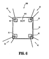
- FIG. 6 is a perspective view of a plurality of different colored sutures in cooperation with a pre-marked mesh having lettering across the anterior side of the mesh, where the lettering indicates that the orientation of the mesh is incorrect, in accordance with the present disclosure
- FIG. 7 is a perspective view of a plurality of different colored sutures in cooperation with a pre-marked mesh having both a bull's eye stamp and lettering across the anterior side of the mesh, where the mesh and the patches on the mesh are circular, in accordance with a second embodiment of the present disclosure
- FIG. 8A is a perspective view of a pre-marked mesh including four regions suitable for inserting surgical fasteners, in accordance with a third embodiment of the present disclosure.
- FIG. 8B is a perspective view of a pre-marked mesh including two regions suitable for inserting surgical fasteners, in accordance with a third embodiment of the present disclosure.
- the present disclosure generally provides a suture material that includes a flexible strand of suture that can have formed thereon at least one marking.
- the marking is adapted to provide various informational properties of the suture to a user of the improved suture material.
- a marking can indicate information relating to at least one use characteristic of the suture.
- An example of a use characteristic may include orientation of the suture.
- correct orientation of the mesh may also be provided by the exemplary embodiments of the present disclosure.
- the present disclosure further provides suture anchor assemblies, methods and devices for anchoring suture to, for example, tissue of a subject.
- the assemblies, methods and devices of the present disclosure provide for the management of suture routing, positioning and identification during surgical procedures, with particular application to procedures that include tissue of a subject by using one or more suture anchors having one or more suture elements mounted thereto.
- the present disclosure also has particular application to arthroscopic surgery, although there is utility in other surgical procedures as well, such as open procedures.
- FIGS. 1-7 generally describe sutures and mesh material that may be incorporated within a suture kit provided to a surgeon.
- FIG. 1 a perspective view of a plurality of different colored sutures in cooperation with a pre-marked mesh, in accordance with the present disclosure is illustrated.
- the suture/mesh configuration 100 of FIG. 1 includes a mesh 20, a first patch 30 having sutures 32, a second patch 40 having sutures 42, a third patch 50 having sutures 52, and a fourth patch 60 having sutures 62.
- the sutures 32, 42, 52, 62 are visually coded to uniquely identify each suture element.
- the patches 30, 40, 50, 60 are also visually coded to uniquely identify each patch element.
- the visual code is preferably a color code.
- one skilled in the art can envision several different visual codes to discern the patches 30, 40, 50, 60 and the sutures 32, 42, 52, 62.
- Such visual codes may include using different suture materials, patterns, designs, shapes, sizes, etc.
- a suture kit is provided incorporating at least the mesh 20, the sutures 32, 42, 52, 62, and the patches 30, 40, 50, 60.
- the suture kit may include at least four contrasting suture colors to aid in the ease of identifying the sutures 32, 42, 52, 62 used to secure the corners of the mesh 20 during, for example, a hernia repair procedure. Each color is assigned to a single suture.
- the first patch 30 provides a visual indicator of the position of the first end of the first suture 32, a visual code to distinguish the first suture 32 from the other sutures 42, 52, 62, and a surface for convenient grasping by the surgeon using forceps or another surgical tool, for manipulating the first suture 32.
- sutures 42, 52, 62 provide visual indicators for distinguishing such sutures from each other.
- patches 30, 40, 50, 60 may be mounted on the mesh 20.
- Any kind of visual code compatible with use in a surgical field can be used, including a color code, a visual pattern displayed on the patches 30, 40, 50, 60, or incorporated into the shape of the patches 30, 40, 50, 60.
- Suture markings for visual coding can incorporate colored wax, markers, tags, or other means.
- a color coding, shape or other identifying characteristics of the patches 30, 40, 50, 60 can match a color coding, shape or other identifying characteristic on the sutures 32, 42, 52, 62.
- the patches 30, 40, 50, 60 are sized for visibility and for convenience of grasping during the surgical procedure. In one embodiment, the patches 30, 40, 50, 60 have a maximum area or length of about 10 mm.
- the patches 30, 40, 50, 60 need not be of equal size.
- the first patch 30 and the second patch 40 may be 10mm in length and the third patch 50 and the fourth patch 60 may be 1 inch in length, depending on desired applications.
- the patches 30, 40, 50, 60 may include an aperture for engagement by a hook, a surgical grasper, or for passing another suture element therethrough.
- tactile elements may be formed into or mounted to the patches 30, 40, 50, 60.
- at least one patch can optionally have one or more holes formed therein, such that suture elements are able to pass therethrough.
- a plurality of patches may be incorporated within each corner of the mesh 20.
- the patches 30, 40, 50, 60 need not only be located on the corners of the mesh 20.
- the patches 30, 40, 50, 60 may be positioned on any location of the mesh 20.
- the sutures 32, 42, 52, 62 may be coated with wax (beeswax, petroleum wax, polyethylene wax, or others), silicone (DOW CORNING ® silicone fluid 202A or others), silicone rubbers (NUSIL TECHNOLOGY TM Med 2245 and Med 2174 with a bonding catalyst, or others) PTFE (TEFLON ® , HOSTAFLON', or others), PBA (polybutylate acid), ethyl cellulose (FILODEL TM ) or other coatings, to improve lubricity of the braid, knot security, or abrasion resistance, for example.
- wax beeswax, petroleum wax, polyethylene wax, or others
- silicone DOW CORNING ® silicone fluid 202A or others
- silicone rubbers NUSIL TECHNOLOGY TM Med 2245 and Med 2174 with a bonding catalyst, or others
- PTFE TEFLON ® , HOSTAFLON', or others
- PBA polybutylate acid
- the sutures 32, 42, 52, 62 may be any combination of natural (clear), white, blue, green, violet, black, or any other non-flesh color to aid in contrast and identification. Also, the sutures 32, 42, 52, 62 may be configured as monofilament, multifilament, braid, barbed, and/or any combination thereof. Moreover, the sutures 32, 42, 52, 62 may consist of absorbable, non-absorbable monomers, polymers, and combinations thereof.
- the mesh 20 may also be marked in four or more regions, such as with four patches 30, 40, 50, 60 corresponding to colors that match the sutures 32, 42, 52, 62.
- the one or more suture markings may be suture color markings and the one or more mesh markings may be mesh color markings, the suture color markings corresponding to the mesh color markings for indicating correct orientation of the mesh material with respect to tissue of a subject.
- each colored suture 32, 42, 52, 62 may correspond to a patch 30, 40, 50, 60 on the mesh 20 having the same color for aiding the surgeon in identifying which suture should be matched with which patch of the mesh 20.
- the color markings of the mesh 20 may be derived by either incorporating dyed yarns in a mesh weave or by a stamping process after the mesh 20 is woven.
- the patches 30, 40, 50, 60 may be of any desirable size. They may be small enough to cover a minor portion of the corner of the mesh 20 or they may be large enough to encompass an entire quadrant of the mesh 20.
- the mesh 20 may also be provided in a plurality of shapes and sizes (see FIG. 7 ). For example, the mesh 20 may be square, rectangular, circular, oval or other shapes typical for repairs where the mesh 20 is utilized.
- the sutures 32, 42, 52, 62 are passed through tissue that is being sutured, and a user is able to discern at least one use characteristic (e.g., orientation) of the suture based on the indications provided by at least one marking that is formed on the suture.
- the marked sutures 32, 42, 52, 62 are advantageous in that they provide an enhanced ease of use of the sutures 32, 42, 52, 62 by a surgeon, and facilitate in alleviating some of the visibility and orientation problems encountered when suturing tissue, particularly in a minimally invasive surgical procedure.
- the suture material of the present disclosure can be otherwise constructed to indicate other use characteristics of the suture material and/or to enhance visibility of the suture.
- at least one marking formed on a flexible strand of suture as described herein can be radiopaque.
- the markings on a suture described herein can be of a contrasting color.
- at least one marking can be of a color other than the color of the suture.
- the markings formed on the sutures described herein can be of a texture different from a texture of the suture.
- the markings can be indented in the strand of suture, or raised on the suture strand.
- the sutures 32, 42, 52, 62 of the present disclosure can include any combination of markings or features described herein, as well as other markings or features known in the art.
- FIG. 2 a perspective view of a plurality of different colored sutures in cooperation with a pre-marked mesh having a bull's eye stamp on the anterior side of the mesh, in accordance with the present disclosure is illustrated.
- the suture/mesh configuration 200 further includes a bull's eye stamp 210.
- the bull's eye stamp 210 may be used as an alternative to coloring the sutures 32, 42, 52, 62 or in addition to coloring the sutures 32, 42, 52, 62. It is possible to apply an adhesive to the mesh 20, to print on the mesh 20, to stamp the mesh 20 and/or to form symbols on the mesh 20. Symbols may also be introduced into the mesh 20 by means of cutouts or the like.
- the mesh 20, or several portions of the mesh 20 in which area the mesh structure of the object is desired to be stamped, can also be referred to as the identification surface/portion/area. Moreover, it is conceivable for the mesh 20 to serve as a support for or to receive any desired parts, not just sutures 32, 42, 52, 62.
- the bull's eye stamp 210 formed on the mesh 20 is preferably formed by means of deformation, in particular as a result of pressure and/or heat. This means that the material forming the bull's eye stamp 210 is heated or compressed until a continuous surface is formed.
- continuous surface does not mean that a completely smooth and homogeneous bull's eye stamp 210 structure need be present. It is acceptable if some interstices remain in the continuous surface, even if the surface is not completely continuous.
- the bull's eye stamp 210 formed on the mesh 20 can be sufficient to serve as a base or support for the information, symbols, writing/lettering, stickers, or other items that are to be applied or introduced. If the purpose of the bull's eye stamp 210 requires, it should be possible for an adhesive to be able to adhere sufficiently firmly to this bull's eye stamp 210.
- the bull's eye stamp 210 may be used to orient/direct the mesh 20. However, the bull's eye stamp 210 may also be used to locate and/or center and/or position the mesh 20 over one or more defects. Also, there may be a plurality of bull's eye stamps 210 in any shape or size across the entire length of the mesh 20.
- FIG. 3 a perspective view of a plurality of different colored sutures in cooperation with a pre-marked mesh having lettering across the anterior side of the mesh, in accordance with the present disclosure is illustrated.
- the suture/mesh configuration 300 further includes a lettering 310.
- lettering 310 may be placed on the surface of the mesh 20.
- the lettering 310 may be placed on the anterior (ventral) facing of the mesh 20.
- the lettering 310 may be any desired word, such as "TOP.”
- the lettering 310 may be positioned on any portion of the mesh 20 in any size and in any color.
- the lettering 310 may consist of a plurality of the same words (e.g., "TOP,” “TOP,” “TOP,”) or different words (e.g., "TOP,” “HERE,” etc.) spread throughout the surface of the mesh 20.
- the lettering 310 may be presented in a serial manner or in a parallel manner and the words may be spaced apart in predetermined horizontal or vertical intervals.
- FIG. 4 a perspective view of a plurality of different colored sutures in cooperation with a pre-marked mesh having both a bull's eye stamp and lettering across the anterior side of the mesh, in accordance with the present disclosure is illustrated.
- the suture/mesh configuration 400 further includes both the bull's eye stamp 210 and the lettering 310.
- the advantages of having both the lettering 310 (e.g., "TOP") and the bull's eye stamp 210 stamped on the anterior side of the mesh 20 would be to assure the surgeon that the proper side of the mesh 20 is in contact with the correct type of tissue of the subject.
- some mesh products have coatings on the posterior (dorsal) side specific to alleviate adhesion, aid in healing, and correct placement of the mesh 20. If the mesh 20 is positioned in an incorrect position (e.g., upside down or backwards), the surgeon would be able to determine that the coating is facing upward or that the lettering is backwards (see FIG. 6 ).
- a combination of different markings may be incorporated within the same mesh 20 of a suture kit.
- FIG. 5 a perspective view of a plurality of different colored sutures in cooperation with a pre-marked mesh having both lettering and arrow-like indicia across the anterior side of the mesh, in accordance with the present disclosure is illustrated.
- the suture/mesh configuration 500 further includes arrow-like indicia 510.
- the arrow-like indicia 510 may be placed on a top surface of the mesh 20 or on an anterior surface of the mesh 20, either at the corners of the mesh 20 or along a length of the mesh 20 in predetermined spaced apart intervals.
- the arrow-like indicia 510 may preferably be placed so that they face one direction.
- one skilled in the art may envision placing a plurality of arrow-like indicia 510 in a number of configurations, where the arrows have different shapes and sizes and colors depending on the desired application.
- a combination of different markings may be incorporated within the same mesh 20 of a suture kit.
- FIG. 6 a perspective view of a plurality of different colored sutures in cooperation with a pre-marked mesh having lettering across the anterior side of the mesh, where the lettering indicates that the orientation of the mesh is incorrect, in accordance with the present disclosure is illustrated.
- suture/mesh configuration 600 further includes lettering 610.
- Lettering 610 indicates to a surgeon using the mesh 20 and the sutures 32, 42, 52, 62 that the mesh 20 has been positioned backwards or upside-down. If the incorrect side of the mesh 20 is placed on the tissue site, the surgeon would see, in this example, the lettering 610 read "9OT” instead of "TOP" and would be inclined to flip the mesh 20 to correct the orientation.
- the lettering may refer to cardinal directions or cardinal points, such as “posterior,” “anterior,” “dorsal,” and “ventral.” Of course, only the initials of the cardinal directions “P,” “A,” “D,” and “V” may be used. Moreover, any type of lettering or phrases or text or symbols in any language may be used to indicate an orientation/direction of the mesh 20.
- FIG. 7 a perspective view of a plurality of different colored sutures in cooperation with a pre-marked mesh having both a bull's eye stamp and lettering across the anterior side of the mesh, where the mesh and the patches on the mesh are circular, in accordance with a second embodiment of the present disclosure is illustrated.
- the suture/mesh configuration 700 includes a mesh 710, a first patch 720 having sutures 722, a second patch 730, a third patch 740, and a fourth patch 750.
- Each of the patches 720, 730, 740, 750 may have a plurality of sutures passed therethrough.
- the mesh 710 includes a bull's eye stamp 760 and lettering 770.
- the suture/mesh configuration 700 illustrates a circular mesh 710 having circular patches 720, 730, 740, 750 positioned on the outer circumference/perimeter of the mesh 710.
- One skilled in the art can envision a plurality of different mesh/suture configurations of a variety of different shapes, sizes, and colors being incorporated within a suture kit.
- FIGS. 8A and 8B a perspective view of a pre-marked mesh including a plurality of regions suitable for inserting tacks, respectively, in accordance with a third embodiment of the present disclosure is presented.
- the mesh design 800A includes a mesh 810 having four regions 820, 830, 840, 850 suitable for firing or inserting fasteners.
- the mesh design 800B includes a mesh 810 having two regions 860, 870 suitable for firing or inserting fasteners.
- the regions 820, 830, 840, 850, 860, 870 are target zones for a medical professional to place fasteners, such as tacks, staples, clips or the like.
- the regions 820, 830, 840, 850, 860, 870 enable the medical professional to ensure correct or accurate positioning of the, for example, tacks in relation to the mesh 810.
- the mesh designs 800A and 800B provide a patch with one or more types of indicia that would help the surgeon ensure that the patch has been properly sized, shaped and positioned and would provide the surgeon with visual guides for fixing the patch to the tissue surrounding the surgical area.
- the regions 820, 830, 840, 850, 860, 870 may include any type of lettering, in any language, in any size to indicate to a surgeon the proper zone for fastening the mesh 810 to the tissue of a patient.
- the lettering "Fire Here" indicates where the surgeon should insert, for example, the tacks.
- the regions 820, 830, 840, 850, 860, 870 may be any shape or size and may be located on any portions of the mesh 810.
- regions 820, 830, 840, 850, 860, 870 may be any shape or size and may be located on any portions of the mesh 810.
- one skilled in the art may contemplate using any type of grid configuration that would act as a visual guide for a surgeon and/or medical professional.
- the markings may also be attached to the mesh 810 by a variety of mechanical means such as sewing or weaving the markings into the mesh material.
- markings such as metal threads may also be attached to the material by adhesive means, such as with bio-compatible glues.
- the regions 820, 830, 840, 850, 860, 870 may be reinforced regions. In other words, regions 820, 830, 840, 850, 860, 870 may be thicker than the mesh 810 in order to accommodate tacks, clips or the like. These reinforced regions may be formed of a material having a higher tensile strength relative to the remainder of the mesh 810 in order to accommodate such tacks, clips or the like.
- one skilled in the art may contemplate using a plurality of the different materials of different tensile strengths to construct a mesh 810 for a desirable application.
- the suture material of the present disclosure can be used in a variety of surgical procedures, for example, for repairing or re-attaching tissue.
- the sutures can be used in a suturing procedure conducted during a minimally invasive surgical procedure, such as an endoscopic or laparoscopic procedure.
- the suture material is used in the context of stitching epidermal disruptions. It will be understood, however, that the method described herein is equally applicable to connecting detached tissue in other contexts as well, such as during open and invasive surgical procedures.
- the improved suture materials of the present disclosure can be formed from a variety of known materials that are suitable for use in forming suture material.
- the exemplary embodiments of the present disclosure can be formed onto the suture material in a variety of processes.
- the various suture markings embodying the present disclosure can be applied to the sutures described herein by an off-set printing process.
- the markings can also be applied to the sutures of the present disclosure by a pad printing process, which can involve obtaining an ink from a master, and subsequently transferring the impression to the suture material.
- a suture anchor assembly according to the present disclosure is provided as a kit including a suture anchor mounted to an insertion tool, and one or more visually coded suture element as described above, pre-mounted to the anchor.
- several different kits are provided, each having unique visual coding of included suture elements, thereby enabling the surgeon to take additional advantage of the suture management capabilities of the present disclosure for multi-anchor procedures.
- Suture anchor assemblies and their application according to the present disclosure have many advantages. These advantages include, but are not limited to, advantages associated with ease of use for the surgeon/user and probable reductions in surgical time and skill required to perform soft tissue repairs. Using suture anchor assemblies according to the present disclosure also reduces the number of suture limbs requiring management about a surgical site, thereby reducing possible confusion and risk of tangling associated with conventional suture configurations.
Landscapes
- Health & Medical Sciences (AREA)
- Life Sciences & Earth Sciences (AREA)
- Surgery (AREA)
- General Health & Medical Sciences (AREA)
- Public Health (AREA)
- Biomedical Technology (AREA)
- Heart & Thoracic Surgery (AREA)
- Veterinary Medicine (AREA)
- Engineering & Computer Science (AREA)
- Animal Behavior & Ethology (AREA)
- Molecular Biology (AREA)
- Nuclear Medicine, Radiotherapy & Molecular Imaging (AREA)
- Medical Informatics (AREA)
- Oral & Maxillofacial Surgery (AREA)
- Cardiology (AREA)
- Transplantation (AREA)
- Vascular Medicine (AREA)
- Pathology (AREA)
- Materials For Medical Uses (AREA)
- Surgical Instruments (AREA)
Abstract
Description
- The present application claims the benefit of and priority to
U.S. Provisional Application Serial No. 61/248,605 filed on October 5, 2009 - The present disclosure relates to mesh and suture kits. Particularly, the present disclosure relates to sutures and mesh material each having one or more markings for identifying the orientation of the mesh relative to tissue of a subject.
- It is well known that suture material is commonly used to repair openings in skin, internal organs, blood vessels, and a variety of other tissues of the human body. Conventionally, suturing of human tissue occurs during open surgery or minimally invasive surgical procedures.
- In certain minimally invasive surgical procedures, e.g., endoscopic and laparoscopic surgeries, a surgeon performs diagnostic and therapeutic procedures at the surgical site through a natural body aperture or through one or more small incisions, using instruments specially designed for this purpose. Problems encountered by a surgeon in such minimally invasive surgical procedures include identifying which suture strands belong in a pair and which belong to a specific corner of a mesh material. Thus, suturing procedures can be particularly challenging in minimally invasive surgical procedures. For example, it can be difficult for a surgeon to determine various properties of the suture material being used, such as the orientation of the mesh and the distinction between the various sutures.
- Additionally, complex or extensive surgical repairs may require the use of several suture anchors and up to several times as many free suture ends. In these procedures, tracking of individual suture strands and their relationship to one another, that is, suture management, can present particular challenges for a surgeon, particularly since such procedures are often arthroscopically performed using remote visualization. The surgeon must be able to identify which suture ends are associated with each suture anchor and with each other, to properly execute a repair and to ensure that a suture is not accidentally demounted from an anchor. In arthroscopic repair procedures, suture management can be particularly difficult because the visibility of the anchors at the surgical site, and of the sutures associated with the anchors, may be very limited. Moreover, the presence of a large number of suture strands extending from a surgical site can result in physical and visual clutter, further increasing the difficulty of the surgical procedure for the surgeon, and presenting a risk of tangling sutures.
- Accordingly, a need exists for an improved suture kit that provides enhanced ease of use and easy identification for managing sutures, particularly in minimally invasive surgical procedures, such as procedures related to hernia repairs.
- The present disclosure is directed to a suture kit including a plurality of flexible strands of suture, each of the strands of suture having one or more suture markings indicative of a suture orientation and a mesh material configured to enable the strands of suture to be passed therethrough, wherein at least one quadrant/section of the mesh material having one or more mesh markings is indicative of a mesh material orientation. The one or more suture markings include visual indicators and the one or more mesh markings include visual indicators, the suture visual indicators correspond to the mesh visual indicators for indicating correct orientation of the mesh material with respect to tissue of a subject.
- According to another aspect of the present disclosure, a method for suturing is disclosed, including providing a suture kit having a plurality of flexible strands of suture and a mesh material, introducing the mesh material into a surgical site, and orientating the mesh material in relation to the surgical site via one or more mesh visual indicators. The next step includes correlating the plurality of flexible strands of suture having one or more suture markings to corresponding mesh markings. Additionally, the fastening of the mesh material to the surgical site via the plurality of flexible strands is performed.
- According to another aspect of the present disclosure, a surgical kit assembly is disclosed including four sutures, each of the four sutures having a different suture color and a mesh layer having four patches, each of the four patches having a different patch color. The suture colors on the sutures correspond to the patch colors on the mesh layer, the mesh layer further including lettering and a bull's eye stamp on the anterior surface of the mesh layer to indicate an orientation of the mesh layer.
- In a preferred embodiment of the invention the mesh material includes lettering placed on a top surface or an anterior surface of the mesh material, preferably the lettering on the top surface or the anterior surface of the material is "TOP."
- The above and other aspects and features of the present disclosure will become more apparent in light of the following detailed description when taken in conjunction with the accompanying drawings in which:
-
FIG. 1 is a perspective view of a plurality of different colored sutures in cooperation with a pre-marked mesh, in accordance with the present disclosure; -
FIG. 2 is a perspective view of a plurality of different colored sutures in cooperation with a pre-marked mesh having a bull's eye stamp on the anterior side of the mesh, in accordance with the present disclosure; -
FIG. 3 is a perspective view of a plurality of different colored sutures in cooperation with a pre-marked mesh having lettering across the anterior side of the mesh, in accordance with the present disclosure; -
FIG. 4 is a perspective view of a plurality of different colored sutures in cooperation with a pre-marked mesh having both a bull's eye stamp and lettering across the anterior side of the mesh, in accordance with the present disclosure; -
FIG. 5 is a perspective view of a plurality of different colored sutures in cooperation with a pre-marked mesh having both lettering and arrow-like indicia across the anterior side of the mesh, in accordance with the present disclosure; -
FIG. 6 is a perspective view of a plurality of different colored sutures in cooperation with a pre-marked mesh having lettering across the anterior side of the mesh, where the lettering indicates that the orientation of the mesh is incorrect, in accordance with the present disclosure; -
FIG. 7 is a perspective view of a plurality of different colored sutures in cooperation with a pre-marked mesh having both a bull's eye stamp and lettering across the anterior side of the mesh, where the mesh and the patches on the mesh are circular, in accordance with a second embodiment of the present disclosure; -
FIG. 8A is a perspective view of a pre-marked mesh including four regions suitable for inserting surgical fasteners, in accordance with a third embodiment of the present disclosure; and -
FIG. 8B is a perspective view of a pre-marked mesh including two regions suitable for inserting surgical fasteners, in accordance with a third embodiment of the present disclosure. - Certain exemplary embodiments will now be described to provide an overall understanding of the principles, structure, function, manufacture, and use of the devices and methods disclosed herein. One or more examples of these embodiments are illustrated in the accompanying drawings. Those skilled in the art will understand that the devices and methods specifically described herein and illustrated in the accompanying drawings are non-limiting exemplary embodiments and that the scope of the present disclosure is defined solely by the claims. The features illustrated or described in connection with one exemplary embodiment may be combined with the features of other embodiments. Such modifications and variations are intended to be included within the scope of the present disclosure.
- The present disclosure generally provides a suture material that includes a flexible strand of suture that can have formed thereon at least one marking. The marking is adapted to provide various informational properties of the suture to a user of the improved suture material. For example, a marking can indicate information relating to at least one use characteristic of the suture. An example of a use characteristic may include orientation of the suture. Additionally, correct orientation of the mesh may also be provided by the exemplary embodiments of the present disclosure.
- The present disclosure further provides suture anchor assemblies, methods and devices for anchoring suture to, for example, tissue of a subject. The assemblies, methods and devices of the present disclosure provide for the management of suture routing, positioning and identification during surgical procedures, with particular application to procedures that include tissue of a subject by using one or more suture anchors having one or more suture elements mounted thereto. The present disclosure also has particular application to arthroscopic surgery, although there is utility in other surgical procedures as well, such as open procedures.
- Particular embodiments of the present disclosure will be described herein with reference to the accompanying drawings.
- Referring now to the drawings, in which like reference numerals identify identical or substantially similar parts throughout the several views,
FIGS. 1-7 generally describe sutures and mesh material that may be incorporated within a suture kit provided to a surgeon. - With reference to
FIG. 1 , a perspective view of a plurality of different colored sutures in cooperation with a pre-marked mesh, in accordance with the present disclosure is illustrated. - The suture/
mesh configuration 100 ofFIG. 1 includes amesh 20, afirst patch 30 havingsutures 32, asecond patch 40 havingsutures 42, athird patch 50 havingsutures 52, and afourth patch 60 havingsutures 62. - The
sutures patches patches sutures mesh 20, thesutures patches sutures mesh 20 during, for example, a hernia repair procedure. Each color is assigned to a single suture. - The
first patch 30 provides a visual indicator of the position of the first end of thefirst suture 32, a visual code to distinguish thefirst suture 32 from theother sutures first suture 32. Similarly, sutures 42, 52, 62 provide visual indicators for distinguishing such sutures from each other. -
Multiple patches mesh 20. Any kind of visual code compatible with use in a surgical field can be used, including a color code, a visual pattern displayed on thepatches patches patches sutures patches patches patches first patch 30 and thesecond patch 40 may be 10mm in length and thethird patch 50 and thefourth patch 60 may be 1 inch in length, depending on desired applications. - In another embodiment, the
patches patches mesh 20. Of course, thepatches mesh 20. Thepatches mesh 20. - The
sutures - The
sutures sutures sutures - The
mesh 20 may also be marked in four or more regions, such as with fourpatches sutures colored suture patch mesh 20 having the same color for aiding the surgeon in identifying which suture should be matched with which patch of themesh 20. - The color markings of the
mesh 20 may be derived by either incorporating dyed yarns in a mesh weave or by a stamping process after themesh 20 is woven. Thepatches mesh 20 or they may be large enough to encompass an entire quadrant of themesh 20. Themesh 20 may also be provided in a plurality of shapes and sizes (seeFIG. 7 ). For example, themesh 20 may be square, rectangular, circular, oval or other shapes typical for repairs where themesh 20 is utilized. - In use, the
sutures sutures - One skilled in the art will appreciate that the suture material of the present disclosure can be otherwise constructed to indicate other use characteristics of the suture material and/or to enhance visibility of the suture. For example, at least one marking formed on a flexible strand of suture as described herein can be radiopaque. Alternatively, the markings on a suture described herein can be of a contrasting color. For example, at least one marking can be of a color other than the color of the suture. Further, the markings formed on the sutures described herein can be of a texture different from a texture of the suture. For example, the markings can be indented in the strand of suture, or raised on the suture strand. In addition, a person skilled in the art will appreciate that the
sutures - With reference to
FIG. 2 , a perspective view of a plurality of different colored sutures in cooperation with a pre-marked mesh having a bull's eye stamp on the anterior side of the mesh, in accordance with the present disclosure is illustrated. - Like reference numerals of
FIG. 1 that identify identical or substantially similar parts ofFIG. 2 will not be described in this section. InFIG. 2 the suture/mesh configuration 200 further includes a bull'seye stamp 210. - The bull's
eye stamp 210 may be used as an alternative to coloring thesutures sutures mesh 20, to print on themesh 20, to stamp themesh 20 and/or to form symbols on themesh 20. Symbols may also be introduced into themesh 20 by means of cutouts or the like. Themesh 20, or several portions of themesh 20 in which area the mesh structure of the object is desired to be stamped, can also be referred to as the identification surface/portion/area. Moreover, it is conceivable for themesh 20 to serve as a support for or to receive any desired parts, not just sutures 32, 42, 52, 62. - The bull's
eye stamp 210 formed on themesh 20 is preferably formed by means of deformation, in particular as a result of pressure and/or heat. This means that the material forming the bull'seye stamp 210 is heated or compressed until a continuous surface is formed. The definition "continuous surface" does not mean that a completely smooth and homogeneous bull'seye stamp 210 structure need be present. It is acceptable if some interstices remain in the continuous surface, even if the surface is not completely continuous. The bull'seye stamp 210 formed on themesh 20 can be sufficient to serve as a base or support for the information, symbols, writing/lettering, stickers, or other items that are to be applied or introduced. If the purpose of the bull'seye stamp 210 requires, it should be possible for an adhesive to be able to adhere sufficiently firmly to this bull'seye stamp 210. - Additionally, the bull's
eye stamp 210 may be used to orient/direct themesh 20. However, the bull'seye stamp 210 may also be used to locate and/or center and/or position themesh 20 over one or more defects. Also, there may be a plurality of bull'seye stamps 210 in any shape or size across the entire length of themesh 20. - With reference to
FIG. 3 , a perspective view of a plurality of different colored sutures in cooperation with a pre-marked mesh having lettering across the anterior side of the mesh, in accordance with the present disclosure is illustrated. - Like reference numerals of
FIG. 1 that identify identical or substantially similar parts ofFIG. 3 will not be described in this section. InFIG. 3 the suture/mesh configuration 300 further includes alettering 310. - Additionally,
lettering 310 may be placed on the surface of themesh 20. Thelettering 310 may be placed on the anterior (ventral) facing of themesh 20. Thelettering 310 may be any desired word, such as "TOP." Thelettering 310 may be positioned on any portion of themesh 20 in any size and in any color. Additionally, thelettering 310 may consist of a plurality of the same words (e.g., "TOP," "TOP," "TOP,") or different words (e.g., "TOP," "HERE," etc.) spread throughout the surface of themesh 20. Thelettering 310 may be presented in a serial manner or in a parallel manner and the words may be spaced apart in predetermined horizontal or vertical intervals. - With reference to
FIG. 4 , a perspective view of a plurality of different colored sutures in cooperation with a pre-marked mesh having both a bull's eye stamp and lettering across the anterior side of the mesh, in accordance with the present disclosure is illustrated. - Like reference numerals of
FIG. 1 that identify identical or substantially similar parts ofFIG. 4 will not be described in this section. InFIG. 4 the suture/mesh configuration 400 further includes both the bull'seye stamp 210 and thelettering 310. - The advantages of having both the lettering 310 (e.g., "TOP") and the bull's
eye stamp 210 stamped on the anterior side of themesh 20 would be to assure the surgeon that the proper side of themesh 20 is in contact with the correct type of tissue of the subject. For example, some mesh products have coatings on the posterior (dorsal) side specific to alleviate adhesion, aid in healing, and correct placement of themesh 20. If themesh 20 is positioned in an incorrect position (e.g., upside down or backwards), the surgeon would be able to determine that the coating is facing upward or that the lettering is backwards (seeFIG. 6 ). Thus, a combination of different markings may be incorporated within thesame mesh 20 of a suture kit. - With reference to
FIG. 5 , a perspective view of a plurality of different colored sutures in cooperation with a pre-marked mesh having both lettering and arrow-like indicia across the anterior side of the mesh, in accordance with the present disclosure is illustrated. - Like reference numerals of
FIG. 1 that identify identical or substantially similar parts ofFIG. 5 will not be described in this section. InFIG. 5 the suture/mesh configuration 500 further includes arrow-like indicia 510. - The arrow-
like indicia 510 may be placed on a top surface of themesh 20 or on an anterior surface of themesh 20, either at the corners of themesh 20 or along a length of themesh 20 in predetermined spaced apart intervals. The arrow-like indicia 510 may preferably be placed so that they face one direction. However, one skilled in the art may envision placing a plurality of arrow-like indicia 510 in a number of configurations, where the arrows have different shapes and sizes and colors depending on the desired application. Thus, a combination of different markings may be incorporated within thesame mesh 20 of a suture kit. - With reference to
FIG. 6 , a perspective view of a plurality of different colored sutures in cooperation with a pre-marked mesh having lettering across the anterior side of the mesh, where the lettering indicates that the orientation of the mesh is incorrect, in accordance with the present disclosure is illustrated. - Like reference numerals of
FIG. 1 that identify identical or substantially similar parts ofFIG. 6 will not be described in this section. InFIG. 6 the suture/mesh configuration 600 further includeslettering 610. -
Lettering 610 indicates to a surgeon using themesh 20 and thesutures mesh 20 has been positioned backwards or upside-down. If the incorrect side of themesh 20 is placed on the tissue site, the surgeon would see, in this example, thelettering 610 read "9OT" instead of "TOP" and would be inclined to flip themesh 20 to correct the orientation. - Additionally, the lettering may refer to cardinal directions or cardinal points, such as "posterior," "anterior," "dorsal," and "ventral." Of course, only the initials of the cardinal directions "P," "A," "D," and "V" may be used. Moreover, any type of lettering or phrases or text or symbols in any language may be used to indicate an orientation/direction of the
mesh 20. - With reference to
FIG. 7 , a perspective view of a plurality of different colored sutures in cooperation with a pre-marked mesh having both a bull's eye stamp and lettering across the anterior side of the mesh, where the mesh and the patches on the mesh are circular, in accordance with a second embodiment of the present disclosure is illustrated. - The suture/
mesh configuration 700 includes amesh 710, afirst patch 720 havingsutures 722, asecond patch 730, athird patch 740, and afourth patch 750. Each of thepatches mesh 710 includes a bull'seye stamp 760 andlettering 770. - The suture/
mesh configuration 700 illustrates acircular mesh 710 havingcircular patches mesh 710. One skilled in the art can envision a plurality of different mesh/suture configurations of a variety of different shapes, sizes, and colors being incorporated within a suture kit. - With reference to
FIGS. 8A and 8B , a perspective view of a pre-marked mesh including a plurality of regions suitable for inserting tacks, respectively, in accordance with a third embodiment of the present disclosure is presented. - In
FIG. 8A , themesh design 800A includes amesh 810 having fourregions FIG. 8B , themesh design 800B includes amesh 810 having tworegions regions regions mesh 810. Thus, the mesh designs 800A and 800B provide a patch with one or more types of indicia that would help the surgeon ensure that the patch has been properly sized, shaped and positioned and would provide the surgeon with visual guides for fixing the patch to the tissue surrounding the surgical area. Theregions mesh 810 to the tissue of a patient. InFIGS. 8A and 8B , the lettering "Fire Here" indicates where the surgeon should insert, for example, the tacks. Theregions mesh 810. Of course, one skilled in the art may contemplate using any type of grid configuration that would act as a visual guide for a surgeon and/or medical professional. - Additionally, the markings may also be attached to the
mesh 810 by a variety of mechanical means such as sewing or weaving the markings into the mesh material. Similarly, markings such as metal threads may also be attached to the material by adhesive means, such as with bio-compatible glues. Moreover, theregions regions mesh 810 in order to accommodate tacks, clips or the like. These reinforced regions may be formed of a material having a higher tensile strength relative to the remainder of themesh 810 in order to accommodate such tacks, clips or the like. Of course, one skilled in the art may contemplate using a plurality of the different materials of different tensile strengths to construct amesh 810 for a desirable application. - In conclusion, the suture material of the present disclosure can be used in a variety of surgical procedures, for example, for repairing or re-attaching tissue. In an exemplary embodiment, the sutures can be used in a suturing procedure conducted during a minimally invasive surgical procedure, such as an endoscopic or laparoscopic procedure. In another exemplary embodiment, the suture material is used in the context of stitching epidermal disruptions. It will be understood, however, that the method described herein is equally applicable to connecting detached tissue in other contexts as well, such as during open and invasive surgical procedures.
- The improved suture materials of the present disclosure can be formed from a variety of known materials that are suitable for use in forming suture material. Moreover, the exemplary embodiments of the present disclosure can be formed onto the suture material in a variety of processes. By way of example, the various suture markings embodying the present disclosure can be applied to the sutures described herein by an off-set printing process. The markings can also be applied to the sutures of the present disclosure by a pad printing process, which can involve obtaining an ink from a master, and subsequently transferring the impression to the suture material.
- In another embodiment, a suture anchor assembly according to the present disclosure is provided as a kit including a suture anchor mounted to an insertion tool, and one or more visually coded suture element as described above, pre-mounted to the anchor. In a further embodiment, several different kits are provided, each having unique visual coding of included suture elements, thereby enabling the surgeon to take additional advantage of the suture management capabilities of the present disclosure for multi-anchor procedures.
- Suture anchor assemblies and their application according to the present disclosure have many advantages. These advantages include, but are not limited to, advantages associated with ease of use for the surgeon/user and probable reductions in surgical time and skill required to perform soft tissue repairs. Using suture anchor assemblies according to the present disclosure also reduces the number of suture limbs requiring management about a surgical site, thereby reducing possible confusion and risk of tangling associated with conventional suture configurations.
- While several embodiments of the disclosure have been shown in the drawings, it is not intended that the disclosure be limited thereto, as it is intended that the disclosure be as broad in scope as the art will allow and that the specification be read likewise. Therefore, the above description should not be construed as limiting, but merely as exemplifications of presently disclosed embodiments. Thus the scope of the embodiments should be determined by the appended claims and their legal equivalents, rather than by the examples given.
- Persons skilled in the art will understand that the devices and methods specifically described herein and illustrated in the accompanying drawings are non-limiting exemplary embodiments. The features illustrated or described in connection with one exemplary embodiment may be combined with the features of other embodiments. Such modifications and variations are intended to be included within the scope of the present disclosure. As well, one skilled in the art will appreciate further features and advantages of the invention based on the above-described embodiments. Accordingly, the present disclosure is not to be limited by what has been particularly shown and described, except as indicated by the appended claims.
Claims (16)
- A suture kit, comprising:a plurality of flexible strands of suture, each of the strands of suture having one or more suture markings indicative of a suture orientation; anda mesh material configured to enable the strands of suture to be passed therethrough, wherein at least one quadrant/section of the mesh material has one or more mesh markings indicative of a mesh material orientation;wherein the one or more suture markings include visual indicators and the one or more mesh markings include visual indicators, the suture visual indicators corresponding to the mesh visual indicators for indicating correct orientation of the mesh material with respect to tissue of a subject.
- The suture kit according to Claim 1, wherein the at least one quadrant/section of the mesh further comprises a patch having one of more markings indicative of a mesh material orientation.
- The suture kit according to Claim 1 or Claim 2, wherein the visual indicators are color markings, preferably wherein the plurality of flexible strands of suture include at least four contrasting color sutures corresponding to at least four contrasting color mesh markings.
- The suture kit according to Claim 3, wherein the at least four contrasting color sutures secure the quadrants/sections of the mesh material to the tissue of the subject during a hernia repair procedure.
- The suture kit according to any preceding Claim, wherein the visual indicators are prepared with a dye process or a stamping process.
- The suture kit according to any preceding Claim, wherein each of the plurality of flexible strands of suture is configured as monofilament, multifilament, barbed or combinations thereof, and/or the suture kit according to any preceding Claim, wherein each of the plurality of flexible strands of suture includes polymers that are absorbable, non-absorbable and combinations thereof.
- The suture kit according to Claim 1, wherein the visual indicators are selected from a group consisting of a plurality of colors, shapes, patterns and/or end effectors.
- The suture kit according to Claim 7, wherein the visual indicators are derived by incorporating dyed yarns in a mesh weave of the mesh material.
- The suture kit according to Claim 1, wherein the visual indicators are derived by a stamping process after the mesh material is woven.
- The suture kit according to any preceding Claim, wherein the mesh material includes lettering placed on a top surface or an anterior surface of the mesh material.
- The suture according to any preceding Claim, wherein the lettering on the top surface or the anterior surface of the material is "TOP."
- The suture kit according to any preceding claim, wherein the mesh material includes a bull's eye stamp placed on a top surface or an anterior surface of the mesh material; and/or the suture kit according to any preceding claim, wherein the mesh material includes arrow-like indicia placed on a top surface or an anterior surface of the mesh material, either at corners of the mesh material or along a length of the mesh material in predetermined spaced apart intervals.
- The suture kit according to any preceding Claim, wherein the mesh visual indicators are of a variable size; and/or the suture kit according to any preceding Claim, wherein the suture visual indicators and the mesh visual indicators are radiopaque.
- A suture kit having a plurality of flexible strands of suture and a mesh material, according to any preceding claim for use in a method of suturing, wherein the method comprises the steps of:;
introducing the mesh material into a surgical site;
orientating the mesh material in relation to the surgical site via one or more mesh visual indicators;
correlating the plurality of flexible strands of suture having one or more suture markings to corresponding mesh markings of the mesh material; and
fastening the mesh material to the surgical site via the plurality of flexible strands. - A suture kit according to Claim 12, further comprising passing four sutures through the mesh material at four corresponding mesh corners/quadrants/sections; and/or further comprising incorporating printed lettering on the mesh material; and/or further comprising incorporating a bull's eye stamp on the mesh material; and/or further comprising incorporating a plurality of indicia on the mesh material; and/or further comprising incorporating dyed yarns in a mesh weave of the mesh material.
- A surgical kit assembly, comprising:four sutures, each of the four sutures having a different suture color; anda mesh layer having four patches, each of the four patches having a different patch color;wherein the suture colors on the sutures correspond to the patch colors on the mesh layer, the mesh layer further including lettering and a bull's eye stamp on the anterior surface of the mesh layer to indicate an orientation of the mesh layer.
Applications Claiming Priority (2)
| Application Number | Priority Date | Filing Date | Title |
|---|---|---|---|
| US24860509P | 2009-10-05 | 2009-10-05 | |
| US12/889,497 US8579922B2 (en) | 2009-10-05 | 2010-09-24 | Method of suture identification and mesh marking for orienting and locating a mesh during hernia repair |
Publications (2)
| Publication Number | Publication Date |
|---|---|
| EP2305132A1 true EP2305132A1 (en) | 2011-04-06 |
| EP2305132B1 EP2305132B1 (en) | 2016-07-27 |
Family
ID=43413663
Family Applications (1)
| Application Number | Title | Priority Date | Filing Date |
|---|---|---|---|
| EP10251733.1A Not-in-force EP2305132B1 (en) | 2009-10-05 | 2010-10-04 | Assembly for suture identification and mesh marking for orienting and locating a mesh during hernia repair |
Country Status (5)
| Country | Link |
|---|---|
| US (1) | US8579922B2 (en) |
| EP (1) | EP2305132B1 (en) |
| JP (2) | JP2011078767A (en) |
| AU (1) | AU2010226934A1 (en) |
| CA (1) | CA2716164A1 (en) |
Cited By (6)
| Publication number | Priority date | Publication date | Assignee | Title |
|---|---|---|---|---|
| WO2014048922A1 (en) * | 2012-09-25 | 2014-04-03 | Sofradim Production | Prosthesis comprising a mesh and a strengthening means |
| WO2016069327A1 (en) * | 2014-10-31 | 2016-05-06 | Prevent Patch, LLC | Devices and methods for preventing incisional hernias |
| WO2016160148A1 (en) * | 2015-03-31 | 2016-10-06 | Prevent Patch, LLC | Devices and methods for preventing incisional hernias |
| US9622844B2 (en) | 2014-10-31 | 2017-04-18 | Prevent Patch, LLC | Devices and methods for preventing incisional hernias |
| CN107072766A (en) * | 2014-10-15 | 2017-08-18 | 强生医疗有限责任公司 | Method of making a marked surgical implant |
| CN108186066A (en) * | 2018-01-12 | 2018-06-22 | 付静 | A kind of operation wire manager |
Families Citing this family (44)
| Publication number | Priority date | Publication date | Assignee | Title |
|---|---|---|---|---|
| JP2013518630A (en) * | 2010-02-02 | 2013-05-23 | ターゲット テープ インコーポレイテッド | Medical procedure location support tool |
| FR2962646B1 (en) * | 2010-07-16 | 2012-06-22 | Sofradim Production | PROSTHETIC WITH RADIO OPAQUE ELEMENT |
| FR2962645B1 (en) * | 2010-07-16 | 2012-06-22 | Sofradim Production | PROSTHETIC MARQUEE |
| FR2968537B1 (en) * | 2010-12-09 | 2013-04-19 | Sofradim Production | PROTHESIS WITH SEWING IN ZIG-ZAG |
| FR2972626B1 (en) | 2011-03-16 | 2014-04-11 | Sofradim Production | PROSTHETIC COMPRISING A THREE-DIMENSIONAL KNIT AND ADJUSTED |
| AU2012230848A1 (en) * | 2011-03-24 | 2013-09-26 | Covidien Lp | Suture loaded umbilical mesh |
| JP6004677B2 (en) | 2011-03-31 | 2016-10-12 | 住友化学株式会社 | Method for producing modified conjugated diene polymer, modified conjugated diene polymer, and polymer composition |
| FR2977789B1 (en) | 2011-07-13 | 2013-07-19 | Sofradim Production | PROSTHETIC FOR UMBILIC HERNIA |
| US20150127103A1 (en) * | 2011-08-02 | 2015-05-07 | Xiros Limited | Connective tissue repair |
| US9492261B2 (en) * | 2011-09-30 | 2016-11-15 | Covidien Lp | Hernia repair device and method |
| FR2985170B1 (en) | 2011-12-29 | 2014-01-24 | Sofradim Production | PROSTHESIS FOR INGUINAL HERNIA |
| FR2985171B1 (en) | 2011-12-29 | 2014-06-06 | Sofradim Production | PROSTHETIC FOR HERNIA WITH MEDIUM MARKING |
| US8932309B2 (en) | 2012-03-06 | 2015-01-13 | Linares Medical Devices, Llc | Surgical polymer molded and flexible covering material with or without secondary composite additive materials for providing anti-bacterial and tear resistant properties |
| US8948871B2 (en) | 2012-07-26 | 2015-02-03 | Nyxoah SA | Electrical contacts on a medical device patch |
| FR2994185B1 (en) | 2012-08-02 | 2015-07-31 | Sofradim Production | PROCESS FOR THE PREPARATION OF A POROUS CHITOSAN LAYER |
| FR2995788B1 (en) | 2012-09-25 | 2014-09-26 | Sofradim Production | HEMOSTATIC PATCH AND PREPARATION METHOD |
| US20160135939A1 (en) * | 2012-12-17 | 2016-05-19 | Atex Technologies, Inc. | Medical textile and methods of making the same |
| US9757221B2 (en) * | 2013-09-16 | 2017-09-12 | Boston Scientific Scimed, Inc. | Medical device and method of making the same |
| US9314244B2 (en) | 2013-12-20 | 2016-04-19 | Medos International Sarl | Directional surgical sutures |
| USD770047S1 (en) | 2014-08-27 | 2016-10-25 | Johnson & Johnson Medical Gmbh | Surgical mesh implant having a floating thread grid marker |
| US9788827B2 (en) | 2014-09-24 | 2017-10-17 | Ethicon, Inc. | Method and means to attach anchor suture onto mesh implants |
| EP3059255B1 (en) | 2015-02-17 | 2020-05-13 | Sofradim Production | Method for preparing a chitosan-based matrix comprising a fiber reinforcement member |
| EP3085337B1 (en) | 2015-04-24 | 2022-09-14 | Sofradim Production | Prosthesis for supporting a breast structure |
| US10111727B2 (en) * | 2015-05-15 | 2018-10-30 | Db Patent Holding Company, Llc | Surgical specimen marking mechanism |
| US12376939B2 (en) | 2015-05-15 | 2025-08-05 | Marginview, Llc | Method of marking a specimen |
| US11464599B1 (en) | 2015-05-15 | 2022-10-11 | Marginview, Llc | Specimen marking mechanism |
| EP3106185B1 (en) | 2015-06-19 | 2018-04-25 | Sofradim Production | Synthetic prosthesis comprising a knit and a non porous film and method for forming same |
| CA3003058A1 (en) * | 2015-10-29 | 2017-05-04 | Sharp Fluidics Llc | Systems and methods for data capture in an operating room |
| DE102015013989A1 (en) * | 2015-10-30 | 2017-05-04 | Johnson & Johnson Medical Gmbh | Surgical implant |
| WO2017074639A1 (en) | 2015-10-30 | 2017-05-04 | Ethicon Llc | Surgical implant |
| EP3195830B1 (en) | 2016-01-25 | 2020-11-18 | Sofradim Production | Prosthesis for hernia repair |
| RU2640560C2 (en) * | 2016-04-22 | 2018-01-09 | Сергей Владимирович Шалашов | Device for plastic surgery of posterior wall of inguinal canal |
| EP3312325B1 (en) | 2016-10-21 | 2021-09-22 | Sofradim Production | Method for forming a mesh having a barbed suture attached thereto and the mesh thus obtained |
| KR101767600B1 (en) | 2016-10-31 | 2017-08-11 | (주)오스테오닉 | mesh-type medical suture anchor |
| EP3398554B1 (en) | 2017-05-02 | 2025-06-25 | Sofradim Production | Prosthesis for inguinal hernia repair |
| WO2019079709A1 (en) * | 2017-10-19 | 2019-04-25 | C.R.Bard, Inc. | Self-gripping hernia prosthesis |
| US12064330B2 (en) | 2020-04-28 | 2024-08-20 | Covidien Lp | Implantable prothesis for minimally invasive hernia repair |
| WO2021222752A1 (en) | 2020-05-01 | 2021-11-04 | Harbor Medtech, Inc. | Port-accessible multidirectional reinforced minimally invasive collagen device for soft tissue repair |
| US12527569B1 (en) | 2020-06-10 | 2026-01-20 | New Wave Endo—Surgical Corp. | Multi-port closure device, corresponding suture material and mesh, a method for repairing and closing a fascial defect, and related devices and methods |
| CN111759539B (en) * | 2020-08-07 | 2022-06-24 | 周锋杰 | Antiskid fixed silicon rubber nose bridge implant |
| USD990679S1 (en) | 2021-06-21 | 2023-06-27 | Marginview, Llc | Tissue specimen marking clip |
| USD1002009S1 (en) | 2021-08-31 | 2023-10-17 | New Wave Endo-Surgical Corp. | Medical device |
| USD1029259S1 (en) | 2021-08-31 | 2024-05-28 | New Wave Endo-Surgical Corp. | Portion of a medical device |
| US12653924B2 (en) * | 2022-11-22 | 2026-06-16 | Cilag Gmbh International | Application of topical skin adhesive to surgical mesh |
Citations (4)
| Publication number | Priority date | Publication date | Assignee | Title |
|---|---|---|---|---|
| WO2002007648A1 (en) * | 2000-07-25 | 2002-01-31 | C.R. Bard, Inc. | Implantable prosthesis |
| US20040019360A1 (en) * | 2002-07-25 | 2004-01-29 | Farnsworth Ted R. | Tissue repair device with a removable support member |
| US20040039453A1 (en) * | 2001-07-27 | 2004-02-26 | Anderson Kimberly A. | Pelvic health implants and methods |
| EP1836970A1 (en) * | 2006-03-23 | 2007-09-26 | Ethicon Endo-Surgery, Inc. | Marked suture |
Family Cites Families (26)
| Publication number | Priority date | Publication date | Assignee | Title |
|---|---|---|---|---|
| US5216700A (en) | 1992-02-18 | 1993-06-01 | George Cherian | Tape having graduated scale providing location indicia during x-ray processes |
| US5474543A (en) * | 1993-05-17 | 1995-12-12 | Mckay; Hunter A. | Single needle apparatus and method for performing retropublic urethropexy |
| US5489294A (en) * | 1994-02-01 | 1996-02-06 | Medtronic, Inc. | Steroid eluting stitch-in chronic cardiac lead |
| JP3568280B2 (en) | 1995-07-12 | 2004-09-22 | 富士写真フイルム株式会社 | Surgical operation support system |
| US5961538A (en) * | 1996-04-10 | 1999-10-05 | Mitek Surgical Products, Inc. | Wedge shaped suture anchor and method of implantation |
| US6254635B1 (en) * | 1998-02-02 | 2001-07-03 | St. Jude Medical, Inc. | Calcification-resistant medical articles |
| US6322571B1 (en) * | 1998-06-05 | 2001-11-27 | Brian D. Adams | Apparatus and method for placing sutures in the lacerated end of a tendon and similar body tissues |
| US6681773B2 (en) | 2001-02-28 | 2004-01-27 | Chase Medical, Inc. | Kit and method for use during ventricular restoration |
| US7029490B2 (en) * | 2001-09-13 | 2006-04-18 | Arthrex, Inc. | High strength suture with coating and colored trace |
| US7163546B2 (en) | 2001-12-21 | 2007-01-16 | Mirizzi Michael S | Method and apparatus for avulsion of varicose veins |
| US6736823B2 (en) * | 2002-05-10 | 2004-05-18 | C.R. Bard, Inc. | Prosthetic repair fabric |
| US7101381B2 (en) * | 2002-08-02 | 2006-09-05 | C.R. Bard, Inc. | Implantable prosthesis |
| US7021316B2 (en) * | 2003-08-07 | 2006-04-04 | Tools For Surgery, Llc | Device and method for tacking a prosthetic screen |
| US20050288691A1 (en) | 2004-06-28 | 2005-12-29 | Leiboff Arnold R | Hernia patch |
| US7975702B2 (en) | 2005-04-05 | 2011-07-12 | El.En. S.P.A. | System and method for laser lipolysis |
| US8506582B2 (en) | 2005-10-25 | 2013-08-13 | Ethicon, Inc. | Template for surgical meshes |
| US7465489B2 (en) * | 2005-11-15 | 2008-12-16 | Poly-Med, Inc. | Inorganic-organic melted-extruded hybrid filaments and medical applications thereof |
| US7894872B2 (en) | 2005-12-26 | 2011-02-22 | Depuy Orthopaedics, Inc | Computer assisted orthopaedic surgery system with light source and associated method |
| WO2007094002A2 (en) | 2006-02-16 | 2007-08-23 | Navotek Medical Ltd. | Location indication by pointing to an intrabody radiation source |
| US20080172073A1 (en) * | 2006-06-16 | 2008-07-17 | Searete Llc, A Limited Liability Corporation Of The State Of Delaware | Active blood vessel sleeve |
| US20080167519A1 (en) * | 2007-01-10 | 2008-07-10 | Pascal St-Germain | Prosthetic repair patch with integrated sutures |
| US20110184441A1 (en) * | 2007-01-10 | 2011-07-28 | Pascal St-Germain | Prosthetic repair patch with integrated sutures and method therefor |
| CA2700531A1 (en) | 2007-09-24 | 2009-04-02 | Surgivision, Inc. | Mri-compatible patches and methods for using the same |
| FR2935604B1 (en) | 2008-09-08 | 2012-01-06 | Centre Nat Rech Scient | METHOD AND DEVICE FOR MARKING A MEDIUM, AND MARKER USABLE IN SUCH A METHOD |
| US8437833B2 (en) | 2008-10-07 | 2013-05-07 | Bard Access Systems, Inc. | Percutaneous magnetic gastrostomy |
| FR2962646B1 (en) * | 2010-07-16 | 2012-06-22 | Sofradim Production | PROSTHETIC WITH RADIO OPAQUE ELEMENT |
-
2010
- 2010-09-24 US US12/889,497 patent/US8579922B2/en not_active Expired - Fee Related
- 2010-10-01 AU AU2010226934A patent/AU2010226934A1/en not_active Abandoned
- 2010-10-04 JP JP2010225270A patent/JP2011078767A/en active Pending
- 2010-10-04 CA CA2716164A patent/CA2716164A1/en not_active Abandoned
- 2010-10-04 EP EP10251733.1A patent/EP2305132B1/en not_active Not-in-force
-
2014
- 2014-08-29 JP JP2014175027A patent/JP2015003051A/en active Pending
Patent Citations (4)
| Publication number | Priority date | Publication date | Assignee | Title |
|---|---|---|---|---|
| WO2002007648A1 (en) * | 2000-07-25 | 2002-01-31 | C.R. Bard, Inc. | Implantable prosthesis |
| US20040039453A1 (en) * | 2001-07-27 | 2004-02-26 | Anderson Kimberly A. | Pelvic health implants and methods |
| US20040019360A1 (en) * | 2002-07-25 | 2004-01-29 | Farnsworth Ted R. | Tissue repair device with a removable support member |
| EP1836970A1 (en) * | 2006-03-23 | 2007-09-26 | Ethicon Endo-Surgery, Inc. | Marked suture |
Cited By (10)
| Publication number | Priority date | Publication date | Assignee | Title |
|---|---|---|---|---|
| WO2014048922A1 (en) * | 2012-09-25 | 2014-04-03 | Sofradim Production | Prosthesis comprising a mesh and a strengthening means |
| US9839505B2 (en) | 2012-09-25 | 2017-12-12 | Sofradim Production | Prosthesis comprising a mesh and a strengthening means |
| CN107072766A (en) * | 2014-10-15 | 2017-08-18 | 强生医疗有限责任公司 | Method of making a marked surgical implant |
| CN107072766B (en) * | 2014-10-15 | 2019-03-12 | 强生医疗有限责任公司 | Method of making a marked surgical implant |
| WO2016069327A1 (en) * | 2014-10-31 | 2016-05-06 | Prevent Patch, LLC | Devices and methods for preventing incisional hernias |
| US9622844B2 (en) | 2014-10-31 | 2017-04-18 | Prevent Patch, LLC | Devices and methods for preventing incisional hernias |
| US9895212B2 (en) | 2014-10-31 | 2018-02-20 | Prevent Patch LLC | Devices and methods for preventing incisional hernias |
| WO2016160148A1 (en) * | 2015-03-31 | 2016-10-06 | Prevent Patch, LLC | Devices and methods for preventing incisional hernias |
| US10603154B2 (en) | 2015-03-31 | 2020-03-31 | Prevent Patch, LLC | Devices and methods for preventing incisional hernias |
| CN108186066A (en) * | 2018-01-12 | 2018-06-22 | 付静 | A kind of operation wire manager |
Also Published As
| Publication number | Publication date |
|---|---|
| US20110082478A1 (en) | 2011-04-07 |
| CA2716164A1 (en) | 2011-04-05 |
| EP2305132B1 (en) | 2016-07-27 |
| JP2011078767A (en) | 2011-04-21 |
| US8579922B2 (en) | 2013-11-12 |
| JP2015003051A (en) | 2015-01-08 |
| AU2010226934A1 (en) | 2011-04-21 |
Similar Documents
| Publication | Publication Date | Title |
|---|---|---|
| US8579922B2 (en) | Method of suture identification and mesh marking for orienting and locating a mesh during hernia repair | |
| AU2007201201B8 (en) | Marked suture | |
| CN102076269B (en) | Coded heterofunctional sutures and methods | |
| EP2255732B1 (en) | Suture management system | |
| US10945823B2 (en) | Guide for selecting and positioning a prosthesis | |
| CN222804389U (en) | Surgical prosthesis | |
| AU2014200502A1 (en) | Hernia mesh placement system and method for in-situ surgical applications | |
| AU2015201685B2 (en) | Coded heterofunctional sutures and methods |
Legal Events
| Date | Code | Title | Description |
|---|---|---|---|
| PUAI | Public reference made under article 153(3) epc to a published international application that has entered the european phase |
Free format text: ORIGINAL CODE: 0009012 |
|
| AK | Designated contracting states |
Kind code of ref document: A1 Designated state(s): AL AT BE BG CH CY CZ DE DK EE ES FI FR GB GR HR HU IE IS IT LI LT LU LV MC MK MT NL NO PL PT RO RS SE SI SK SM TR |
|
| AX | Request for extension of the european patent |
Extension state: BA ME |
|
| 17P | Request for examination filed |
Effective date: 20111004 |
|
| RAP1 | Party data changed (applicant data changed or rights of an application transferred) |
Owner name: COVIDIEN LP |
|
| 17Q | First examination report despatched |
Effective date: 20141111 |
|
| GRAP | Despatch of communication of intention to grant a patent |
Free format text: ORIGINAL CODE: EPIDOSNIGR1 |
|
| INTG | Intention to grant announced |
Effective date: 20150929 |
|
| INTG | Intention to grant announced |
Effective date: 20160210 |
|
| RIC1 | Information provided on ipc code assigned before grant |
Ipc: A61B 17/06 20060101AFI20160201BHEP Ipc: A61B 90/90 20160101ALN20160201BHEP Ipc: A61B 17/00 20060101ALN20160201BHEP Ipc: A61F 2/00 20060101ALN20160201BHEP |
|
| GRAS | Grant fee paid |
Free format text: ORIGINAL CODE: EPIDOSNIGR3 |
|
| GRAA | (expected) grant |
Free format text: ORIGINAL CODE: 0009210 |
|
| RIN1 | Information on inventor provided before grant (corrected) |
Inventor name: GLICK, JONATHAN P Inventor name: SCHIRETZ, RICHARD |
|
| AK | Designated contracting states |
Kind code of ref document: B1 Designated state(s): AL AT BE BG CH CY CZ DE DK EE ES FI FR GB GR HR HU IE IS IT LI LT LU LV MC MK MT NL NO PL PT RO RS SE SI SK SM TR |
|
| REG | Reference to a national code |
Ref country code: GB Ref legal event code: FG4D |
|
| REG | Reference to a national code |
Ref country code: CH Ref legal event code: EP |
|
| REG | Reference to a national code |
Ref country code: AT Ref legal event code: REF Ref document number: 815133 Country of ref document: AT Kind code of ref document: T Effective date: 20160815 |
|
| REG | Reference to a national code |
Ref country code: IE Ref legal event code: FG4D |
|
| REG | Reference to a national code |
Ref country code: DE Ref legal event code: R096 Ref document number: 602010035008 Country of ref document: DE |
|
| REG | Reference to a national code |
Ref country code: FR Ref legal event code: PLFP Year of fee payment: 7 |
|
| PGFP | Annual fee paid to national office [announced via postgrant information from national office to epo] |
Ref country code: GB Payment date: 20160928 Year of fee payment: 7 Ref country code: IE Payment date: 20160922 Year of fee payment: 7 |
|
| REG | Reference to a national code |
Ref country code: LT Ref legal event code: MG4D |
|
| REG | Reference to a national code |
Ref country code: NL Ref legal event code: MP Effective date: 20160727 |
|
| REG | Reference to a national code |
Ref country code: AT Ref legal event code: MK05 Ref document number: 815133 Country of ref document: AT Kind code of ref document: T Effective date: 20160727 |
|
| PG25 | Lapsed in a contracting state [announced via postgrant information from national office to epo] |
Ref country code: NL Free format text: LAPSE BECAUSE OF FAILURE TO SUBMIT A TRANSLATION OF THE DESCRIPTION OR TO PAY THE FEE WITHIN THE PRESCRIBED TIME-LIMIT Effective date: 20160727 Ref country code: IS Free format text: LAPSE BECAUSE OF FAILURE TO SUBMIT A TRANSLATION OF THE DESCRIPTION OR TO PAY THE FEE WITHIN THE PRESCRIBED TIME-LIMIT Effective date: 20161127 Ref country code: NO Free format text: LAPSE BECAUSE OF FAILURE TO SUBMIT A TRANSLATION OF THE DESCRIPTION OR TO PAY THE FEE WITHIN THE PRESCRIBED TIME-LIMIT Effective date: 20161027 Ref country code: RS Free format text: LAPSE BECAUSE OF FAILURE TO SUBMIT A TRANSLATION OF THE DESCRIPTION OR TO PAY THE FEE WITHIN THE PRESCRIBED TIME-LIMIT Effective date: 20160727 Ref country code: HR Free format text: LAPSE BECAUSE OF FAILURE TO SUBMIT A TRANSLATION OF THE DESCRIPTION OR TO PAY THE FEE WITHIN THE PRESCRIBED TIME-LIMIT Effective date: 20160727 Ref country code: IT Free format text: LAPSE BECAUSE OF FAILURE TO SUBMIT A TRANSLATION OF THE DESCRIPTION OR TO PAY THE FEE WITHIN THE PRESCRIBED TIME-LIMIT Effective date: 20160727 Ref country code: LT Free format text: LAPSE BECAUSE OF FAILURE TO SUBMIT A TRANSLATION OF THE DESCRIPTION OR TO PAY THE FEE WITHIN THE PRESCRIBED TIME-LIMIT Effective date: 20160727 Ref country code: FI Free format text: LAPSE BECAUSE OF FAILURE TO SUBMIT A TRANSLATION OF THE DESCRIPTION OR TO PAY THE FEE WITHIN THE PRESCRIBED TIME-LIMIT Effective date: 20160727 |
|
| PG25 | Lapsed in a contracting state [announced via postgrant information from national office to epo] |
Ref country code: GR Free format text: LAPSE BECAUSE OF FAILURE TO SUBMIT A TRANSLATION OF THE DESCRIPTION OR TO PAY THE FEE WITHIN THE PRESCRIBED TIME-LIMIT Effective date: 20161028 Ref country code: AT Free format text: LAPSE BECAUSE OF FAILURE TO SUBMIT A TRANSLATION OF THE DESCRIPTION OR TO PAY THE FEE WITHIN THE PRESCRIBED TIME-LIMIT Effective date: 20160727 Ref country code: LV Free format text: LAPSE BECAUSE OF FAILURE TO SUBMIT A TRANSLATION OF THE DESCRIPTION OR TO PAY THE FEE WITHIN THE PRESCRIBED TIME-LIMIT Effective date: 20160727 Ref country code: SE Free format text: LAPSE BECAUSE OF FAILURE TO SUBMIT A TRANSLATION OF THE DESCRIPTION OR TO PAY THE FEE WITHIN THE PRESCRIBED TIME-LIMIT Effective date: 20160727 Ref country code: BE Free format text: LAPSE BECAUSE OF NON-PAYMENT OF DUE FEES Effective date: 20160727 Ref country code: PT Free format text: LAPSE BECAUSE OF FAILURE TO SUBMIT A TRANSLATION OF THE DESCRIPTION OR TO PAY THE FEE WITHIN THE PRESCRIBED TIME-LIMIT Effective date: 20161128 Ref country code: ES Free format text: LAPSE BECAUSE OF FAILURE TO SUBMIT A TRANSLATION OF THE DESCRIPTION OR TO PAY THE FEE WITHIN THE PRESCRIBED TIME-LIMIT Effective date: 20160727 Ref country code: PL Free format text: LAPSE BECAUSE OF FAILURE TO SUBMIT A TRANSLATION OF THE DESCRIPTION OR TO PAY THE FEE WITHIN THE PRESCRIBED TIME-LIMIT Effective date: 20160727 |
|
| PG25 | Lapsed in a contracting state [announced via postgrant information from national office to epo] |
Ref country code: RO Free format text: LAPSE BECAUSE OF FAILURE TO SUBMIT A TRANSLATION OF THE DESCRIPTION OR TO PAY THE FEE WITHIN THE PRESCRIBED TIME-LIMIT Effective date: 20160727 Ref country code: EE Free format text: LAPSE BECAUSE OF FAILURE TO SUBMIT A TRANSLATION OF THE DESCRIPTION OR TO PAY THE FEE WITHIN THE PRESCRIBED TIME-LIMIT Effective date: 20160727 |
|
| REG | Reference to a national code |
Ref country code: DE Ref legal event code: R097 Ref document number: 602010035008 Country of ref document: DE |
|
| PG25 | Lapsed in a contracting state [announced via postgrant information from national office to epo] |
Ref country code: DK Free format text: LAPSE BECAUSE OF FAILURE TO SUBMIT A TRANSLATION OF THE DESCRIPTION OR TO PAY THE FEE WITHIN THE PRESCRIBED TIME-LIMIT Effective date: 20160727 Ref country code: BG Free format text: LAPSE BECAUSE OF FAILURE TO SUBMIT A TRANSLATION OF THE DESCRIPTION OR TO PAY THE FEE WITHIN THE PRESCRIBED TIME-LIMIT Effective date: 20161027 Ref country code: SM Free format text: LAPSE BECAUSE OF FAILURE TO SUBMIT A TRANSLATION OF THE DESCRIPTION OR TO PAY THE FEE WITHIN THE PRESCRIBED TIME-LIMIT Effective date: 20160727 Ref country code: CZ Free format text: LAPSE BECAUSE OF FAILURE TO SUBMIT A TRANSLATION OF THE DESCRIPTION OR TO PAY THE FEE WITHIN THE PRESCRIBED TIME-LIMIT Effective date: 20160727 Ref country code: SK Free format text: LAPSE BECAUSE OF FAILURE TO SUBMIT A TRANSLATION OF THE DESCRIPTION OR TO PAY THE FEE WITHIN THE PRESCRIBED TIME-LIMIT Effective date: 20160727 |
|
| REG | Reference to a national code |
Ref country code: CH Ref legal event code: PL |
|
| PLBE | No opposition filed within time limit |
Free format text: ORIGINAL CODE: 0009261 |
|
| STAA | Information on the status of an ep patent application or granted ep patent |
Free format text: STATUS: NO OPPOSITION FILED WITHIN TIME LIMIT |
|
| 26N | No opposition filed |
Effective date: 20170502 |
|
| PG25 | Lapsed in a contracting state [announced via postgrant information from national office to epo] |
Ref country code: LI Free format text: LAPSE BECAUSE OF NON-PAYMENT OF DUE FEES Effective date: 20161031 Ref country code: CH Free format text: LAPSE BECAUSE OF NON-PAYMENT OF DUE FEES Effective date: 20161031 |
|
| PG25 | Lapsed in a contracting state [announced via postgrant information from national office to epo] |
Ref country code: SI Free format text: LAPSE BECAUSE OF FAILURE TO SUBMIT A TRANSLATION OF THE DESCRIPTION OR TO PAY THE FEE WITHIN THE PRESCRIBED TIME-LIMIT Effective date: 20160727 Ref country code: LU Free format text: LAPSE BECAUSE OF NON-PAYMENT OF DUE FEES Effective date: 20161004 |
|
| REG | Reference to a national code |
Ref country code: FR Ref legal event code: PLFP Year of fee payment: 8 |
|
| PG25 | Lapsed in a contracting state [announced via postgrant information from national office to epo] |
Ref country code: CY Free format text: LAPSE BECAUSE OF FAILURE TO SUBMIT A TRANSLATION OF THE DESCRIPTION OR TO PAY THE FEE WITHIN THE PRESCRIBED TIME-LIMIT Effective date: 20160727 Ref country code: HU Free format text: LAPSE BECAUSE OF FAILURE TO SUBMIT A TRANSLATION OF THE DESCRIPTION OR TO PAY THE FEE WITHIN THE PRESCRIBED TIME-LIMIT; INVALID AB INITIO Effective date: 20101004 |
|
| GBPC | Gb: european patent ceased through non-payment of renewal fee |
Effective date: 20171004 |
|
| PG25 | Lapsed in a contracting state [announced via postgrant information from national office to epo] |
Ref country code: MT Free format text: LAPSE BECAUSE OF NON-PAYMENT OF DUE FEES Effective date: 20161031 Ref country code: TR Free format text: LAPSE BECAUSE OF FAILURE TO SUBMIT A TRANSLATION OF THE DESCRIPTION OR TO PAY THE FEE WITHIN THE PRESCRIBED TIME-LIMIT Effective date: 20160727 Ref country code: MC Free format text: LAPSE BECAUSE OF FAILURE TO SUBMIT A TRANSLATION OF THE DESCRIPTION OR TO PAY THE FEE WITHIN THE PRESCRIBED TIME-LIMIT Effective date: 20160727 Ref country code: MK Free format text: LAPSE BECAUSE OF FAILURE TO SUBMIT A TRANSLATION OF THE DESCRIPTION OR TO PAY THE FEE WITHIN THE PRESCRIBED TIME-LIMIT Effective date: 20160727 |
|
| REG | Reference to a national code |
Ref country code: IE Ref legal event code: MM4A |
|
| PG25 | Lapsed in a contracting state [announced via postgrant information from national office to epo] |
Ref country code: GB Free format text: LAPSE BECAUSE OF NON-PAYMENT OF DUE FEES Effective date: 20171004 |
|
| REG | Reference to a national code |
Ref country code: FR Ref legal event code: PLFP Year of fee payment: 9 |
|
| PG25 | Lapsed in a contracting state [announced via postgrant information from national office to epo] |
Ref country code: IE Free format text: LAPSE BECAUSE OF NON-PAYMENT OF DUE FEES Effective date: 20171004 Ref country code: AL Free format text: LAPSE BECAUSE OF FAILURE TO SUBMIT A TRANSLATION OF THE DESCRIPTION OR TO PAY THE FEE WITHIN THE PRESCRIBED TIME-LIMIT Effective date: 20160727 |
|
| PGFP | Annual fee paid to national office [announced via postgrant information from national office to epo] |
Ref country code: FR Payment date: 20180920 Year of fee payment: 9 |
|
| PGFP | Annual fee paid to national office [announced via postgrant information from national office to epo] |
Ref country code: DE Payment date: 20180819 Year of fee payment: 9 |
|
| REG | Reference to a national code |
Ref country code: DE Ref legal event code: R119 Ref document number: 602010035008 Country of ref document: DE |
|
| PG25 | Lapsed in a contracting state [announced via postgrant information from national office to epo] |
Ref country code: DE Free format text: LAPSE BECAUSE OF NON-PAYMENT OF DUE FEES Effective date: 20200501 |
|
| PG25 | Lapsed in a contracting state [announced via postgrant information from national office to epo] |
Ref country code: FR Free format text: LAPSE BECAUSE OF NON-PAYMENT OF DUE FEES Effective date: 20191031 |