EP2304472B1 - Marine seismic acquisition with controlled streamer flaring - Google Patents
Marine seismic acquisition with controlled streamer flaring Download PDFInfo
- Publication number
- EP2304472B1 EP2304472B1 EP09774052.6A EP09774052A EP2304472B1 EP 2304472 B1 EP2304472 B1 EP 2304472B1 EP 09774052 A EP09774052 A EP 09774052A EP 2304472 B1 EP2304472 B1 EP 2304472B1
- Authority
- EP
- European Patent Office
- Prior art keywords
- seismic
- streamers
- marine
- receivers
- range
- Prior art date
- Legal status (The legal status is an assumption and is not a legal conclusion. Google has not performed a legal analysis and makes no representation as to the accuracy of the status listed.)
- Active
Links
Images


Classifications
-
- G—PHYSICS
- G01—MEASURING; TESTING
- G01V—GEOPHYSICS; GRAVITATIONAL MEASUREMENTS; DETECTING MASSES OR OBJECTS; TAGS
- G01V1/00—Seismology; Seismic or acoustic prospecting or detecting
- G01V1/38—Seismology; Seismic or acoustic prospecting or detecting specially adapted for water-covered areas
-
- G—PHYSICS
- G01—MEASURING; TESTING
- G01V—GEOPHYSICS; GRAVITATIONAL MEASUREMENTS; DETECTING MASSES OR OBJECTS; TAGS
- G01V1/00—Seismology; Seismic or acoustic prospecting or detecting
- G01V1/38—Seismology; Seismic or acoustic prospecting or detecting specially adapted for water-covered areas
- G01V1/3817—Positioning of seismic devices
Definitions
- the present invention relates to seismic data acquisition. More particularly, the invention relates to the acquisition of seismic data in marine environments.
- Marine seismic exploration investigates and maps the structure and character of subsurface geological formations underlying a body of water.
- Marine seismic data is typically gathered by towing seismic sources (e.g., air guns) and seismic receivers (e.g., hydrophones) through a body of water behind one or more marine vessels.
- seismic sources and receivers are towed through the water, the seismic sources generate acoustic pulses that travel through the water and into the earth, where they are reflected and/or refracted by interfaces between subsurface geological formations.
- the seismic receivers sense the resulting reflected and/or refracted energy, thereby acquiring seismic data that provides information about the geological formations underlying the body of water.
- seismic receivers typically an array of thousands of seismic receivers is used to gather marine seismic data.
- the seismic receivers are generally attached to streamer cables that are towed behind the marine vessel. It is known that the relative positions of the marine seismic receivers during seismic data acquisition can affect the quality and utility of the resulting seismic data.
- unpredictable environmental forces such as currents, winds, and sea states present in many marine environments can cause the relative positions of marine seismic receivers to vary greatly as they are towed through the water. Therefore, it is common for steering devices (commonly know as "birds") to be attached to the streamer cables so that the relative positions (both lateral and vertical) of the seismic receivers can be controlled as they are towed through the water.
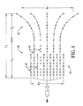
- FIG. 1 is a simplified depiction of a conventional marine seismic data acquisition system employing a marine vessel 10 to tow seismic sources 12 and a system 14 of steerable seismic streamers 16 through a body of water 18.
- Each of the seismic streamers 16 includes a streamer cable 20, a series of seismic receivers 22 coupled to the cable 20, and a series of steering devices 24 coupled to the cable 20.
- the steering devices 24 are used to maintain substantially constant lateral spacing between the seismic streamers 16.
- a system of this type is disclosed in US-A-2009262601 .
- Gaps in seismic data can be caused by a number of factors including, for example, skewing of the seismic streamers relative to the direction of travel of the towing vessel during data acquisition. Even when steerable streamers are employed, gaps in seismic data are common, particularly when strong crosscurrents are present. When strong crosscurrents are present during seismic data acquisition, it is not practical to maintain all the streamers in an orientation that is parallel to the direction of travel of the towing vessel because fighting strong crosscurrents with steering devices produces noise that dramatically reduces the quality of the gathered seismic data.
- a method of acquiring seismic data in a marine environment comprises:
- a marine seismic data acquisition system according to one embodiment of the present invention is illustrated as generally comprising a marine vessel 30, marine seismic sources 32, and a marine seismic streamer system 34.
- the marine seismic streamer system 34 of FIG. 2 is depicted in a flared configuration.
- the streamer system 34 is intentionally maintained in a flare configuration and is used to gather marine seismic data, while the marine vessel 30 tows the seismic sources 32 and the streamer system 34 through a body of water 38.
- the marine vessel 30 can be any vessel capable of towing the seismic sources 32 and the seismic streamer system 34 through the body of water 38 at an appropriate speed.
- appropriate speeds for the marine seismic data acquisition methods of the present invention can be in the range of 2 to 10 knots, or most commonly 4 to 6 knots.
- the marine seismic sources 32 can be any submersible acoustic wave source capable of generating wave energy powerful enough to propagate through the body of water 38 and into a subsea region of the earth, where it is reflected and/or refracted to thereby produce reflected/refracted energy that carries information about the structure of the subsea region and is detectable by marine seismic receivers. Although two seismic sources 32 are illustrated in FIG. 2 , it may be desirable to use only one seismic source. Alternatively, the vessel may have no seismic source(s), such as in the case where the vessel is only towing streamers. Alternatively, it may be desirable to use three or more seismic sources in either single or multiple vessel operations.
- the seismic sources 32 are air guns.
- One example of a suitable air gun is available from ION Geophysical of Houston, TX under the commercial designation SLEEVE GUNTM.
- the marine seismic streamer system 34 includes a plurality of laterally-spaced individual marine seismic streamers 36.
- the marine seismic streamers 36 can each include a streamer cable 38, a series of longitudinally-spaced marine seismic receivers 40 coupled to the cable 38, and a series of steering devices 42 coupled to the cable 38.
- the marine seismic streamer system 34 employs in the range of 4 to 50 individual seismic streamers 36, or optionally in the range of 5 to 25 individual seismic streamers 36.
- the seismic streamers 36 have a length in the range of 2 to 20 kilometers, or optionally in the range of 4 to 12 kilometers.
- the individual seismic streamers 36 can each include in the range of 10 to 300,000 individual seismic receivers 40, in the range of 100 to 10,000 individual seismic receivers 40, or in the range of 200 to 1,000 individual seismic receivers 40.
- the seismic receivers 40 employed in the present invention can be selected from a wide variety of commonly known marine seismic receivers.
- a suitable seismic receiver is available from Teledyne Benthos of North Falmouth, MA under the commercial designation AQ_2000TM.
- the seismic streamers 36 illustrated in FIG. 2 are steerable streamers whose lateral positions can be controlled by the steering devices 42 as the streamers 36 are towed through the water 38.
- the individual seismic streamers 36 can each include at least 3 steering devices 42, at least 10 steering devices 42, or at least 20 steering devices. Although all the seismic streamers 36 depicted in FIG. 2 are steerable streamers that include steering devices 42, it should be understood that one or more of the streamers 36 may not be equipped with any steering devices. In one embodiment, at least one-half of the seismic streamers 36 are steerable streamers equipped with steering devices 42.
- the steering devices 42 employed in the present invention can be selected from a wide variety of commonly known steering devices.
- the steering devices 42 are capable of controlling both the lateral position and the depth of the seismic streamers 36 in the body of water 38.
- One such steering device is available from WestemGeco LLC of Houston, TX under the commercial designation Q_FINTM.
- FIG. 2 depicts the seismic streamer system 34 in a flared configuration, where the rear portion of the streamer system 34 is wider than the front portion of the streamer system 34.
- the seismic streamer system 34 is in a flared configuration when the lateral distance (d r ) between the outer-most, rearward-most seismic receivers 40a,b is greater than the lateral distance (d f ) between the outer-most, front-most seismic receivers 40c,d.
- the seismic streamer system 34 is in a flared configuration when the lateral distance (d r ) between the outer-most, rearward-most seismic receivers 40a,b is at least 2 percent, at least 5 percent, at least 10 percent, at least 20 percent, or in the range of 30 to 400 percent greater than the lateral distance (d f ) between the outer-most, frontmost seismic receivers 40c,d.
- the average spacing between adjacent seismic receivers 40 of a front-most group 44 of seismic receivers 40 can be in the range of 0.1 to 300 meters, in the range of 1 to 100 meters, or in the range of 4 to 50 meters.
- the average spacing between adjacent seismic receivers 40 of a rearward-most group 46 of seismic receivers 40 is at least 2 percent, may be at least 5 percent, at least 10 percent, at least 20 percent, or in the range of 30 to 400 percent greater than the average spacing between adjacent seismic receivers 40 of the front-most group 44 of seismic receivers 40.
- the average spacing between adjacent seismic receivers 40 of the rearward-most group 46 of seismic receivers 40 is in the range of 15 to 250 meters, or may be in the range of 25 to 150 meters.
- the seismic streamer system 34 depicted in FIG. 2 has a generally trapezoidal shape, with a substantially constant rate of flaring along the entire length of the seismic streamer system 34.
- rate of flaring is used to denote the rate at which the average spacing between adjacent seismic streamers increases rearwardly along a certain length of the seismic streamer system.
- FIG. 3 depicts an alternative seismic streamer system 50 in a f1 ared configuration.
- seismic streamer system 50 has a trumpet-shaped configuration, with a rearwardly increasing rate of flaring in a flared section 52 of the seismic streamer system 50.
- the "flared section" of a seismic streamer system is simply the section of the seismic streamer system that is in a flared configuration.
- the entire length of the streamer system 34 would be considered a flared section.
- the flared section 52 has a length (l f ) that is less than the total length (l t ) of the seismic streamer system 50.
- the seismic streamer system 50 can also include a non-flared/straight section 54 that exhibits a substantially constant streamer spacing over its length (l s ).
- the length (l f ) of the flared section of a seismic streamer system can be at least 5 percent, at least 10 percent, at least 20 percent, at least 40 percent, at least 60 percent, at least 80 percent, or at least 100 percent of the total length (l t ) of the seismic streamer system.
- the flared section of a seismic streamer system can exhibit an average lateral spacing between adjacent seismic streamers that increases rearwardly at a rate of at least 0.001 meters (lateral) per meter (longitudinal), at least 0.002 meters per meter, at least 0.005 meters per meter, at least 0.01 meters per meter, at least 0.05 meters per meter, or at least 0.1 meters per meter.
- FIG. 5 outlines certain steps that can be used to carry out a marine seismic data acquisition method according to embodiments of the present invention.
- a marine vessel tows a seismic streamer system to a location where a seismic data acquisition pass is to be performed.
- a desired flared streamer configuration is determined.
- flared streamer configurations include, but are not limited to, configurations similar to those depicted in FIGS. 2-4 .
- step 104 while the seismic streamer system is being towed through the water, the relative positions of the streamers and/or seismic receivers are checked to determine if the seismic streamer system is in the desired flared configuration.
- step 106 a determination is made as to whether the seismic streamer system is in the desired flared configuration. If the seismic streamer system is not in the desired flared configuration, step 108 adjusts the steering devices so as to steer to seismic streamer system from an undesirable, non-flared configuration toward the desired flared configuration. Steps 104, 106, and 108 can then be repeated until the seismic streamer system is in the desired flared configuration.
- seismic data acquisition can be initiated by exciting marine seismic sources and detecting reflected and/or refracted wave energy with the seismic receivers of the seismic streamer system.
- steps 104, 106, 108 can be repeated in order to ensure that the seismic streamer system is in the desired flared configuration.
- decision is made whether or not the current seismic data acquisition pass is complete.
- step 116 if the current seismic data acquisition pass is not complete, seismic data acquisition is continued. Thereafter, steps 104, 106, 108, 110, 114, and 116 arc repeated to ensure that the seismic streamer system is maintained in the desired flared configuration during seismic data acquisition.
- step 118 a determination is made in step 118 as to whether another seismic data acquisition pass is desired. If another pass is desired, the process returns to step 100. If another pass is not desired, the seismic data acquisition process is complete, as depicted in step 120.
- the marine seismic data acquisition method intentionally controls the position of the seismic streamers in a flared configuration while the streamers are being towed through the water and seismic data is being acquired.
- the seismic streamer system is continuously maintained in a flared configuration over a controlled flaring distance of at least one kilometer, at least five kilometers, or at least 15 kilometers.
- the seismic streamer system is continuously maintained in the flared configuration for a controlled flaring time of at least five minutes, at least 20 minutes, at least 60 minutes, or at least 120 minutes. During the controlled flaring time and/or over the controlled flaring distance, the seismic streamer system is used to gather marine seismic data.
- the term "and/or,” when used in a list of two or more items, means that anyone of the listed items can be employed by itself, or any combination of two or more of the listed items can be employed.
- the composition can contain A alone; B alone; C alone; A and B in combination; A and C in combination; B and C in combination; or A, B, and C in combination.
- the terms “comprising,” “comprises,” and “comprise” are open-ended transition terms used to transition from a subject recited before the term to one or elements recited after the term, where the element or elements listed after the transition term are not necessarily the only elements that make up the subject.
- the terms “having,” “has,” and “have” have the same open-ended meaning as “comprising,” “comprises,” and “comprise,” provided above.
- the terms “including,” “includes,” and “include” have the same open ended meaning as “comprising,” “comprises,” and “comprise,” provided above.
Landscapes
- Life Sciences & Earth Sciences (AREA)
- Physics & Mathematics (AREA)
- Oceanography (AREA)
- Engineering & Computer Science (AREA)
- Acoustics & Sound (AREA)
- Environmental & Geological Engineering (AREA)
- Geology (AREA)
- Remote Sensing (AREA)
- General Life Sciences & Earth Sciences (AREA)
- General Physics & Mathematics (AREA)
- Geophysics (AREA)
- Geophysics And Detection Of Objects (AREA)
Description
- The present invention relates to seismic data acquisition. More particularly, the invention relates to the acquisition of seismic data in marine environments.
- Marine seismic exploration investigates and maps the structure and character of subsurface geological formations underlying a body of water. Marine seismic data is typically gathered by towing seismic sources (e.g., air guns) and seismic receivers (e.g., hydrophones) through a body of water behind one or more marine vessels. As the seismic sources and receivers are towed through the water, the seismic sources generate acoustic pulses that travel through the water and into the earth, where they are reflected and/or refracted by interfaces between subsurface geological formations. The seismic receivers sense the resulting reflected and/or refracted energy, thereby acquiring seismic data that provides information about the geological formations underlying the body of water.
- Typically an array of thousands of seismic receivers is used to gather marine seismic data. The seismic receivers are generally attached to streamer cables that are towed behind the marine vessel. It is known that the relative positions of the marine seismic receivers during seismic data acquisition can affect the quality and utility of the resulting seismic data. However, unpredictable environmental forces such as currents, winds, and sea states present in many marine environments can cause the relative positions of marine seismic receivers to vary greatly as they are towed through the water. Therefore, it is common for steering devices (commonly know as "birds") to be attached to the streamer cables so that the relative positions (both lateral and vertical) of the seismic receivers can be controlled as they are towed through the water.
-
FIG. 1 is a simplified depiction of a conventional marine seismic data acquisition system employing amarine vessel 10 to towseismic sources 12 and asystem 14 of steerableseismic streamers 16 through a body ofwater 18. Each of theseismic streamers 16 includes astreamer cable 20, a series ofseismic receivers 22 coupled to thecable 20, and a series ofsteering devices 24 coupled to thecable 20. As depicted inFIG. 1 , during conventional marine seismic acquisition, thesteering devices 24 are used to maintain substantially constant lateral spacing between theseismic streamers 16. A system of this type is disclosed inUS-A-2009262601 . - A common problem encountered with conventional marine seismic surveys is "gaps" in the acquired seismic data. These data gaps can occur when the spacing between adjacent acquisition passes is too large to provide sufficient resolution for proper data processing. Gaps in seismic data can be caused by a number of factors including, for example, skewing of the seismic streamers relative to the direction of travel of the towing vessel during data acquisition. Even when steerable streamers are employed, gaps in seismic data are common, particularly when strong crosscurrents are present. When strong crosscurrents are present during seismic data acquisition, it is not practical to maintain all the streamers in an orientation that is parallel to the direction of travel of the towing vessel because fighting strong crosscurrents with steering devices produces noise that dramatically reduces the quality of the gathered seismic data.
- When gaps in marine seismic data are discovered, the areas corresponding to the data gaps must be resurveyed - a process commonly known as "shooting in-fill" or "in-filling." Unfortunately, the existence of gaps in marine seismic data may not be discovered until the initial marine seismic survey has been completed and the resulting seismic data is being processed. Obviously, in-filling is very undesirable because of the significant expense and time involved in resurveying in-fill areas that may be located hundreds of kilometers from one another or even retransiting the same vessel pass again to make up coverage.
US3840845 discloses a two-streamer arrangement where the near ends of the streamers are coincident.EP-A-0525391 discloses the use of two parallel streamers and two highly flared streamers at an angle of 30 degrees or more to the towing line. - In accordance with the present invention, a method of acquiring seismic data in a marine environment, said method comprises:
- (a) towing a system of 4 to 50 laterally-spaced steerable seismic streamers through a body of water, wherein each of said seismic streamers comprises a series of longitudinally-spaced marine seismic receivers, characterised by:
- (b) simultaneously with step (a), steering said system of seismic streamers into a flared configuration where (i) all the streamers have a length of between 2km and 20km, (ii) the lateral distance between the outer-most, rearward-most marine seismic receivers is at least 2 percent greater than the lateral distance between the outer-most, forward-most marine seismic receivers, (iii) the average lateral spacing between adjacent seismic receivers of the rearward-most group of seismic receivers is in the range of 15 to 250 meters; and
- (c) simultaneously with steps (a) and (b), recording reflected and/or refracted seismic data with said marine seismic receivers.
- Although the prior art teaches that streamer flaring during seismic data acquisition should be avoided, the inventors have discovered that the use of controlled streamer flaring can reduce or eliminate the need for in-filling, without requiring more equipment or more acquisition passes than conventional marine seismic surveying techniques.
-
FIG. 1 is a simplified depiction of a conventional marine seismic acquisition system in a non-flared configuration where the lateral spacing between the streamers is substantially constant over the entire length of the streamers. -
FIG. 2 is a simplified depiction of an exemplary inventive marine seismic acquisition system in a flared configuration, particularly illustrating a trapezoidally shaped system of seismic streamers exhibiting lateral streamer spacing that increases rearwardly at a substantially constant rate over the entire length of the streamers. -
FIG. 3 is a simplified depiction of an exemplary inventive marine seismic acquisition system in a flared configuration, particularly illustrating a trumpet-shaped system of seismic streamers exhibiting lateral streamer spacing that increases rearwardly at an increasing rate. -
FIG. 4 is a simplified depiction of an exemplary inventive marine seismic acquisition system in a flared configuration, particularly illustrating a trumpet-shaped system of variable length seismic streamers exhibiting lateral streamer spacing that increases rearwardly at an increasing rate. - Referring initially to
FIG. 2 , a marine seismic data acquisition system according to one embodiment of the present invention is illustrated as generally comprising amarine vessel 30, marineseismic sources 32, and a marineseismic streamer system 34. The marineseismic streamer system 34 ofFIG. 2 is depicted in a flared configuration. In accordance with various embodiments of the inventive marine seismic data acquisition process described herein, thestreamer system 34 is intentionally maintained in a flare configuration and is used to gather marine seismic data, while themarine vessel 30 tows theseismic sources 32 and thestreamer system 34 through a body ofwater 38. - The
marine vessel 30 can be any vessel capable of towing theseismic sources 32 and theseismic streamer system 34 through the body ofwater 38 at an appropriate speed. Generally, appropriate speeds for the marine seismic data acquisition methods of the present invention can be in the range of 2 to 10 knots, or most commonly 4 to 6 knots. - The marine
seismic sources 32 can be any submersible acoustic wave source capable of generating wave energy powerful enough to propagate through the body ofwater 38 and into a subsea region of the earth, where it is reflected and/or refracted to thereby produce reflected/refracted energy that carries information about the structure of the subsea region and is detectable by marine seismic receivers. Although twoseismic sources 32 are illustrated inFIG. 2 , it may be desirable to use only one seismic source. Alternatively, the vessel may have no seismic source(s), such as in the case where the vessel is only towing streamers. Alternatively, it may be desirable to use three or more seismic sources in either single or multiple vessel operations. One skilled in the art will recognize that a variety of types of equipment can be employed as theseismic sources 32 depending on the conditions of the marine environment and design parameters of the seismic survey. In one embodiment, the marineseismic sources 32 are air guns. One example of a suitable air gun is available from ION Geophysical of Houston, TX under the commercial designation SLEEVE GUN™. - As illustrated in
FIG. 2 , the marineseismic streamer system 34 includes a plurality of laterally-spaced individual marineseismic streamers 36. The marineseismic streamers 36 can each include astreamer cable 38, a series of longitudinally-spaced marineseismic receivers 40 coupled to thecable 38, and a series ofsteering devices 42 coupled to thecable 38. - The marine
seismic streamer system 34 employs in the range of 4 to 50 individualseismic streamers 36, or optionally in the range of 5 to 25 individualseismic streamers 36. Theseismic streamers 36 have a length in the range of 2 to 20 kilometers, or optionally in the range of 4 to 12 kilometers. - The individual
seismic streamers 36 can each include in the range of 10 to 300,000 individualseismic receivers 40, in the range of 100 to 10,000 individualseismic receivers 40, or in the range of 200 to 1,000 individualseismic receivers 40. Theseismic receivers 40 employed in the present invention can be selected from a wide variety of commonly known marine seismic receivers. One example a suitable seismic receiver is available from Teledyne Benthos of North Falmouth, MA under the commercial designation AQ_2000™. - The
seismic streamers 36 illustrated inFIG. 2 are steerable streamers whose lateral positions can be controlled by thesteering devices 42 as thestreamers 36 are towed through thewater 38. The individualseismic streamers 36 can each include at least 3steering devices 42, at least 10steering devices 42, or at least 20 steering devices. Although all theseismic streamers 36 depicted inFIG. 2 are steerable streamers that includesteering devices 42, it should be understood that one or more of thestreamers 36 may not be equipped with any steering devices. In one embodiment, at least one-half of theseismic streamers 36 are steerable streamers equipped withsteering devices 42. Thesteering devices 42 employed in the present invention can be selected from a wide variety of commonly known steering devices. In accordance with one embodiment of the present invention, thesteering devices 42 are capable of controlling both the lateral position and the depth of theseismic streamers 36 in the body ofwater 38. One such steering device is available from WestemGeco LLC of Houston, TX under the commercial designation Q_FIN™. - As noted above,
FIG. 2 depicts theseismic streamer system 34 in a flared configuration, where the rear portion of thestreamer system 34 is wider than the front portion of thestreamer system 34. In accordance with one embodiment of the present invention, theseismic streamer system 34 is in a flared configuration when the lateral distance (dr) between the outer-most, rearward-mostseismic receivers 40a,b is greater than the lateral distance (df) between the outer-most, front-mostseismic receivers 40c,d. In other embodiments, theseismic streamer system 34 is in a flared configuration when the lateral distance (dr) between the outer-most, rearward-mostseismic receivers 40a,b is at least 2 percent, at least 5 percent, at least 10 percent, at least 20 percent, or in the range of 30 to 400 percent greater than the lateral distance (df) between the outer-most, frontmostseismic receivers 40c,d. - Referring again to
FIG. 2 , the average spacing between adjacentseismic receivers 40 of afront-most group 44 ofseismic receivers 40 can be in the range of 0.1 to 300 meters, in the range of 1 to 100 meters, or in the range of 4 to 50 meters. The average spacing between adjacentseismic receivers 40 of arearward-most group 46 ofseismic receivers 40 is at least 2 percent, may be at least 5 percent, at least 10 percent, at least 20 percent, or in the range of 30 to 400 percent greater than the average spacing between adjacentseismic receivers 40 of thefront-most group 44 ofseismic receivers 40. The average spacing between adjacentseismic receivers 40 of therearward-most group 46 ofseismic receivers 40 is in the range of 15 to 250 meters, or may be in the range of 25 to 150 meters. - The
seismic streamer system 34 depicted inFIG. 2 has a generally trapezoidal shape, with a substantially constant rate of flaring along the entire length of theseismic streamer system 34. As used herein, the term "rate of flaring" is used to denote the rate at which the average spacing between adjacent seismic streamers increases rearwardly along a certain length of the seismic streamer system. -
FIG. 3 depicts an alternativeseismic streamer system 50 in a f1 ared configuration. In particular,seismic streamer system 50 has a trumpet-shaped configuration, with a rearwardly increasing rate of flaring in a flaredsection 52 of theseismic streamer system 50. As used herein, the "flared section" of a seismic streamer system is simply the section of the seismic streamer system that is in a flared configuration. Thus, for theseismic streamer system 34 ofFIG. 1 , the entire length of thestreamer system 34 would be considered a flared section. However, for theseismic streamer system 50 ofFIG. 3 , the flaredsection 52 has a length (lf) that is less than the total length (lt) of theseismic streamer system 50. As depicted inFIG. 3 theseismic streamer system 50 can also include a non-flared/straight section 54 that exhibits a substantially constant streamer spacing over its length (ls). - In accordance with various embodiments of the present invention, the length (lf) of the flared section of a seismic streamer system can be at least 5 percent, at least 10 percent, at least 20 percent, at least 40 percent, at least 60 percent, at least 80 percent, or at least 100 percent of the total length (lt) of the seismic streamer system. In accordance with embodiments of the present invention, the flared section of a seismic streamer system can exhibit an average lateral spacing between adjacent seismic streamers that increases rearwardly at a rate of at least 0.001 meters (lateral) per meter (longitudinal), at least 0.002 meters per meter, at least 0.005 meters per meter, at least 0.01 meters per meter, at least 0.05 meters per meter, or at least 0.1 meters per meter.
- FIG. 5 outlines certain steps that can be used to carry out a marine seismic data acquisition method according to embodiments of the present invention. In step 100, a marine vessel tows a seismic streamer system to a location where a seismic data acquisition pass is to be performed. In step 102, a desired flared streamer configuration is determined. As discussed above, a wide variety of flared streamer configurations can be employed in the seismic data acquisition process. These flared streamer configurations include, but are not limited to, configurations similar to those depicted in
FIGS. 2-4 . - In step 104, while the seismic streamer system is being towed through the water, the relative positions of the streamers and/or seismic receivers are checked to determine if the seismic streamer system is in the desired flared configuration. In step 106, a determination is made as to whether the seismic streamer system is in the desired flared configuration. If the seismic streamer system is not in the desired flared configuration, step 108 adjusts the steering devices so as to steer to seismic streamer system from an undesirable, non-flared configuration toward the desired flared configuration. Steps 104, 106, and 108 can then be repeated until the seismic streamer system is in the desired flared configuration.
- As depicted in steps 110 and 112, once the seismic streamer system is in the desired flared configuration, seismic data acquisition can be initiated by exciting marine seismic sources and detecting reflected and/or refracted wave energy with the seismic receivers of the seismic streamer system. After initiation of seismic data acquisition, steps 104, 106, 108 can be repeated in order to ensure that the seismic streamer system is in the desired flared configuration. In step 114, decision is made whether or not the current seismic data acquisition pass is complete. As depicted in step 116, if the current seismic data acquisition pass is not complete, seismic data acquisition is continued. Thereafter, steps 104, 106, 108, 110, 114, and 116 arc repeated to ensure that the seismic streamer system is maintained in the desired flared configuration during seismic data acquisition. After it is determined in step 114 that the current seismic data acquisition pass is complete, a determination is made in step 118 as to whether another seismic data acquisition pass is desired. If another pass is desired, the process returns to step 100. If another pass is not desired, the seismic data acquisition process is complete, as depicted in step 120.
- As mentioned above, the marine seismic data acquisition method according to embodiments of the present invention intentionally controls the position of the seismic streamers in a flared configuration while the streamers are being towed through the water and seismic data is being acquired. In certain embodiments of the present invention, the seismic streamer system is continuously maintained in a flared configuration over a controlled flaring distance of at least one kilometer, at least five kilometers, or at least 15 kilometers. In certain embodiments of the present invention, the seismic streamer system is continuously maintained in the flared configuration for a controlled flaring time of at least five minutes, at least 20 minutes, at least 60 minutes, or at least 120 minutes. During the controlled flaring time and/or over the controlled flaring distance, the seismic streamer system is used to gather marine seismic data.
- The present description uses numerical ranges to quantify certain parameters relating to the invention. It should be understood that when numerical ranges are provided, such ranges are to be construed as providing literal suppOli for claim limitations that only recite the lower value of the range as well as claims limitation that only recite the upper value of the range. For example, a disclosed numerical range of 10 to 100 provides literal support for a claim reciting "greater than 10" (with no upper bounds) and a claim reciting "less than 100" (with no lower bounds).
- As used herein, the terms "a," "an," "the," and "said" mean one or more.
- As used herein, the term "and/or," when used in a list of two or more items, means that anyone of the listed items can be employed by itself, or any combination of two or more of the listed items can be employed. For example, if a composition is described as containing components A, B, and/or C, the composition can contain A alone; B alone; C alone; A and B in combination; A and C in combination; B and C in combination; or A, B, and C in combination.
- As used herein, the terms "comprising," "comprises," and "comprise" are open-ended transition terms used to transition from a subject recited before the term to one or elements recited after the term, where the element or elements listed after the transition term are not necessarily the only elements that make up the subject.
- As used herein, the terms "containing," "contains," and "contain" have the same open-ended meaning as "comprising," "comprises," and "comprise," provided below.
- As used herein, the terms "having," "has," and "have" have the same open-ended meaning as "comprising," "comprises," and "comprise," provided above. As used herein, the terms "including," "includes," and "include" have the same open ended meaning as "comprising," "comprises," and "comprise," provided above.
Claims (13)
- A method of acquiring seismic data in a marine environment, said method comprising:(a) towing a system (34) of 4 to 50 laterally-spaced steerable seismic streamers (36) through a body of water, wherein each of said seismic streamers (36) comprises a series of longitudinally-spaced marine seismic receivers (40), characterised by:(b) simultaneously with step (a), steering said system of seismic streamers (36) into a flared configuration where (i) all the streamers have a length of between 2km and 20km, (ii) the lateral distance (dr) between the outer-most, rearward-most marine seismic receivers (40) is at least 2 percent greater than the lateral distance (df) between the outer-most, forward-most marine seismic receivers, (iii) the average lateral spacing between adjacent seismic receivers of the rearward-most group (46) of seismic receivers is in the range of 15 to 250 meters; and(c) simultaneously with steps (a) and (b), recording reflected and/or refracted seismic data with said marine seismic receivers (40).
- The method of claim 1 wherein when said system (34) of seismic streamers (36) is in said flared configuration the lateral distance (dr) between the outer-most, rearward-most marine seismic receivers is at least 5 percent greater than the lateral distance (df) between the outer-most, forward-most marine seismic receivers.
- The method of claim 1 wherein when said system (34) of seismic streamers (36) is in said flared configuration the average lateral spacing between said seismic streamers in a flared section of said system of seismic streamers increases rearwardly at a rate of at least 0.001 meters per meter, wherein said flared section of said system of seismic streamers has a length that is at least 20 percent of the total length of said system of seismic streamers.
- The method of claim 1 wherein at least two of said seismic streamers (36) include a series of longitudinally-spaced steering devices (42) capable of controlling the lateral position of said seismic streamers (36) during said towing of step (a).
- The method of claim 4 wherein each of said seismic streamers (36) comprises at least three of said steering devices (42).
- The method of claim 4 wherein said steering devices (42) are capable of simultaneously controlling both the lateral position and the depth of said seismic streamers in said body of water.
- The method of claim 1 wherein said system (34) of seismic streamers (36) comprises in the range of 3 to 100 individual streamers.
- The method of claim 1 wherein each of said seismic streamers (36) comprises in the range of 10 to 300,000 of said marine seismic receivers (40).
- The method of claim 1 wherein said towing of step (a) is carried out at a speed in the range of 2 to 10 knots.
- The method of claim 1 wherein at least one-half of said seismic streamers (36) comprise a series of longitudinally-spaced steering devices (42) capable of controlling the lateral position of said seismic streamers (36) during said towing of step (a), wherein said system (34) of seismic streamers (36) comprises in the range of 4 to 50 individual streamers (36), wherein each of said seismic streamers (36) has a length in the range of 2 to 20 kilometers, wherein each of said seismic streamers (36) includes in the range of 100 to 10,000 of said marine seismic receivers (40), wherein the average lateral spacing between a forward-most group of said marine seismic receivers (40) is in the range of 1 to 100 meters, wherein the average lateral spacing between a rearward-most group of said marine seismic receivers (40) is at least 10 percent greater than the average lateral spacing between said forward-most group of said marine seismic receivers (40).
- The method of claim 1 wherein said system of seismic streamers is continuously maintained in said flared configuration over a controlled flaring distance of at least one kilometer, wherein over said controlled flaring distance the average lateral distance between the outer-most, rearward-most marine seismic receivers is at least 10 percent greater than the average lateral distance between the outer-most, forward-most marine seismic receivers.
- The method of claim 11, wherein said controlled flaring distance is at least five kilometers, wherein over said controlled flaring distance the average lateral distance between the outer-most, rearward-most marine seismic receivers is at least 20 percent greater than the average lateral distance between the outer-most, forward-most marine seismic receivers.
- The method of claim 12 wherein each of said seismic streamers comprises a series of longitudinally-spaced steering devices capable of controlling the lateral position of said seismic streamers during said towing of step (a), wherein said system of seismic streamers comprises in the range of 5 to 25 individual streamers, wherein each of said seismic streamers has a length in the range of 4 to 12 kilometers, wherein each of said seismic streamers includes in the range of 200 to 1,000 of said marine seismic receivers, wherein the average lateral spacing between a forward-most group of said marine seismic receivers is in the range of 4 to 50 meters.
Priority Applications (1)
| Application Number | Priority Date | Filing Date | Title |
|---|---|---|---|
| EP13189158.2A EP2711739B1 (en) | 2008-07-03 | 2009-06-18 | Marine seismic acquisition with controlled streamer flaring |
Applications Claiming Priority (2)
| Application Number | Priority Date | Filing Date | Title |
|---|---|---|---|
| US12/167,683 US8391101B2 (en) | 2008-07-03 | 2008-07-03 | Marine seismic acquisition with controlled streamer flaring |
| PCT/US2009/047756 WO2010002600A2 (en) | 2008-07-03 | 2009-06-18 | Marine seismic acquisition with controlled streamer flaring |
Related Child Applications (2)
| Application Number | Title | Priority Date | Filing Date |
|---|---|---|---|
| EP13189158.2A Division EP2711739B1 (en) | 2008-07-03 | 2009-06-18 | Marine seismic acquisition with controlled streamer flaring |
| EP13189158.2A Division-Into EP2711739B1 (en) | 2008-07-03 | 2009-06-18 | Marine seismic acquisition with controlled streamer flaring |
Publications (2)
| Publication Number | Publication Date |
|---|---|
| EP2304472A2 EP2304472A2 (en) | 2011-04-06 |
| EP2304472B1 true EP2304472B1 (en) | 2014-05-14 |
Family
ID=41396447
Family Applications (2)
| Application Number | Title | Priority Date | Filing Date |
|---|---|---|---|
| EP13189158.2A Active EP2711739B1 (en) | 2008-07-03 | 2009-06-18 | Marine seismic acquisition with controlled streamer flaring |
| EP09774052.6A Active EP2304472B1 (en) | 2008-07-03 | 2009-06-18 | Marine seismic acquisition with controlled streamer flaring |
Family Applications Before (1)
| Application Number | Title | Priority Date | Filing Date |
|---|---|---|---|
| EP13189158.2A Active EP2711739B1 (en) | 2008-07-03 | 2009-06-18 | Marine seismic acquisition with controlled streamer flaring |
Country Status (6)
| Country | Link |
|---|---|
| US (1) | US8391101B2 (en) |
| EP (2) | EP2711739B1 (en) |
| AU (1) | AU2009264966B2 (en) |
| CA (1) | CA2727439C (en) |
| DK (1) | DK2304472T3 (en) |
| WO (1) | WO2010002600A2 (en) |
Families Citing this family (40)
| Publication number | Priority date | Publication date | Assignee | Title |
|---|---|---|---|---|
| US7400552B2 (en) | 2006-01-19 | 2008-07-15 | Westerngeco L.L.C. | Methods and systems for efficiently acquiring towed streamer seismic surveys |
| US8488409B2 (en) | 2007-05-17 | 2013-07-16 | Westerngeco L.L.C. | Acquiring azimuth rich seismic data in the marine environment using a regular sparse pattern of continuously curved sail lines |
| US8681580B2 (en) | 2008-05-15 | 2014-03-25 | Westerngeco L.L.C. | Multi-vessel coil shooting acquisition |
| US9857491B2 (en) | 2008-05-15 | 2018-01-02 | Westerngeco L.L.C. | Multi-vessel coil shooting acquisition |
| US8724426B2 (en) * | 2008-06-03 | 2014-05-13 | Westerngeco L.L.C. | Marine seismic streamer system configurations, systems, and methods for non-linear seismic survey navigation |
| US9594181B2 (en) | 2008-06-13 | 2017-03-14 | Westerngeco L.L.C. | Filtering and presentation of heading observations for coil shooting |
| US9052411B2 (en) | 2008-06-13 | 2015-06-09 | Westerngeco L.L.C. | Method to determine the deviation of seismic equipment from a planned curved path |
| US20100103773A1 (en) * | 2008-10-29 | 2010-04-29 | Conocophillips Company | Simultaneous Multiple Source Extended Inversion |
| US9213119B2 (en) * | 2008-10-29 | 2015-12-15 | Conocophillips Company | Marine seismic acquisition |
| CA2741865C (en) | 2008-11-10 | 2015-05-12 | Conocophillips Company | Practical autonomous seismic recorder implementation and use |
| AU2010319714B2 (en) | 2009-11-11 | 2014-02-13 | Conocophillips Company | Seismic acquisition in marine environments using survey paths following a series of linked deviated paths and methods of use |
| EP2507654B1 (en) * | 2009-12-02 | 2022-09-28 | ConocoPhillips Company | Extraction of discrete records from continuous seismic recordings |
| EP2577355B1 (en) * | 2010-06-07 | 2023-07-26 | ConocoPhillips Company | Flaring methodologies for marine seismic data acquisition |
| CA3092055C (en) * | 2010-06-09 | 2022-07-12 | Conocophillips Company | Seismic data acquisition using designed non-uniform receiver spacing |
| WO2012061735A2 (en) * | 2010-11-05 | 2012-05-10 | Conocophillips Company | Active steering curved and flared seismic streamers |
| US8730760B2 (en) * | 2011-04-05 | 2014-05-20 | Pgs Geophysical As | Method for seismic surveying using wider lateral spacing between sources to improve efficiency |
| US10459099B2 (en) | 2011-09-22 | 2019-10-29 | Cgg Services Sas | Device and method to determine shape of streamer |
| US9103942B2 (en) | 2011-10-28 | 2015-08-11 | Westerngeco L.L.C. | Methods and systems for survey designs |
| EP2771722B1 (en) | 2011-10-28 | 2018-08-22 | GX Technology Canada Ltd. | Steerable fairing string |
| US9001615B2 (en) | 2011-11-08 | 2015-04-07 | Conocophillips Company | Oscillating flared streamers |
| WO2013070195A1 (en) * | 2011-11-08 | 2013-05-16 | Conocophillips Company | Oscillating flared streamers |
| US10795041B2 (en) * | 2012-10-16 | 2020-10-06 | Conocophillips Company | Flared pseudo-random spiral marine acquisition |
| EP2889646A1 (en) * | 2013-12-31 | 2015-07-01 | Sercel | Method and device for steering a seismic vessel, on the basis of boundaries of binning coverage zones |
| EP3227728B1 (en) * | 2014-12-01 | 2020-08-12 | Subvision AB | A system and method for sea bed surveying |
| WO2016100797A1 (en) | 2014-12-18 | 2016-06-23 | Conocophillips Company | Methods for simultaneous source separation |
| AU2016332565B2 (en) | 2015-09-28 | 2022-07-21 | Shearwater Geoservices Software Inc. | 3D seismic acquisition |
| RU2729696C2 (en) * | 2015-10-15 | 2020-08-11 | Ион Джиофизикал Корпорейшн | Dynamically controlled wing systems and methods |
| EP3764129A1 (en) | 2016-02-16 | 2021-01-13 | GX Technology Canada Ltd. | Ribbon foil depressor |
| US11035968B2 (en) | 2016-11-02 | 2021-06-15 | Conocophillips Company | Use nuos technology to acquire optimized 2D data |
| JP6849999B2 (en) * | 2017-04-25 | 2021-03-31 | 国立大学法人東京海洋大学 | Submarine geological exploration system, submarine geological exploration method and submarine geological exploration program |
| US10809402B2 (en) | 2017-05-16 | 2020-10-20 | Conocophillips Company | Non-uniform optimal survey design principles |
| AU2018368796B2 (en) | 2017-11-20 | 2023-10-12 | Shearwater Geoservices Software Inc. | Offshore application of non-uniform optimal sampling survey design |
| EP3857268B1 (en) | 2018-09-30 | 2024-10-23 | Shearwater Geoservices Software Inc. | Machine learning based signal recovery |
| CN113382922B (en) | 2018-10-09 | 2024-07-19 | Gx技术加拿大有限公司 | Modular airfoil system for towed ocean arrays |
| US12066585B2 (en) | 2020-02-07 | 2024-08-20 | Pgs Geophysical As | Wide-tow source surveying with subline infill |
| US12105239B2 (en) | 2020-09-25 | 2024-10-01 | Pgs Geophysical As | Surveying with non-uniform survey configuration with wide-tow source geometry |
| JP7664060B2 (en) * | 2021-03-12 | 2025-04-17 | ヤンマーホールディングス株式会社 | Navigation equipment and vessel |
| US12377942B1 (en) * | 2022-04-19 | 2025-08-05 | Brunswick Corporation | Systems and methods for detecting waves and controlling a marine vessel based on the detected waves |
| JP7439162B2 (en) * | 2022-04-21 | 2024-02-27 | ヤマハ発動機株式会社 | Ship speed control method and ship |
| US12566436B2 (en) * | 2023-06-13 | 2026-03-03 | Honda Motor Co., Ltd | Maneuvering control devices for vessels, vessels |
Citations (2)
| Publication number | Priority date | Publication date | Assignee | Title |
|---|---|---|---|---|
| AU2039892A (en) * | 1991-08-01 | 1993-02-04 | Prakla-Seismos Gmbh | Method for marine seismic data aquisition |
| US20060256654A1 (en) * | 2005-05-12 | 2006-11-16 | Paulsen Jens O | Seismic streamer receiver selection systems and methods |
Family Cites Families (15)
| Publication number | Priority date | Publication date | Assignee | Title |
|---|---|---|---|---|
| US3840845A (en) * | 1973-06-29 | 1974-10-08 | Chevron Res | Method of initiating and collecting seismic data related to strata underlying bodies of water using a continuously moving seismic exploration system located on a single boat using separate streamers |
| NO830358L (en) | 1983-02-02 | 1984-08-03 | Kongsberg Vaapenfabrik Corp Bu | DEVICE FOR A HYDROPHONE CABLE FOR MARINE SEISM STUDIES |
| US5353223A (en) * | 1992-10-26 | 1994-10-04 | Western Atlas International, Inc. | Marine navigation method for geophysical exploration |
| GB9424744D0 (en) | 1994-12-08 | 1995-02-08 | Geco As | Method of and apparatus for marine seismic surveying |
| US5790472A (en) * | 1996-12-20 | 1998-08-04 | Western Atlas International, Inc. | Adaptive control of marine seismic streamers |
| US6285956B1 (en) * | 1997-12-30 | 2001-09-04 | Westerngeco, Llc | Marine Seismic tow system |
| GB9821277D0 (en) * | 1998-10-01 | 1998-11-25 | Geco As | Seismic data acquisition equipment control system |
| US6629037B1 (en) | 2000-06-26 | 2003-09-30 | Westerngeco, L.L.C. | Optimal paths for marine data collection |
| US6691038B2 (en) * | 2001-06-15 | 2004-02-10 | Westerngeco L.L.C. | Active separation tracking and positioning system for towed seismic arrays |
| US7092315B2 (en) * | 2004-05-27 | 2006-08-15 | Input/Output, Inc. | Device for laterally steering streamer cables |
| US7167412B2 (en) * | 2004-12-17 | 2007-01-23 | Pgs Americas, Inc. | Apparatus for steering a marine seismic streamer via controlled bending |
| US7450467B2 (en) * | 2005-04-08 | 2008-11-11 | Westerngeco L.L.C. | Apparatus and methods for seismic streamer positioning |
| US7203130B1 (en) * | 2006-03-21 | 2007-04-10 | Westerngeco, L.L.C. | Methods for deriving shape of seismic data acquisition cables and streamers employing a force model |
| DE602006007130D1 (en) | 2006-07-12 | 2009-07-16 | Kongsberg Seatex As | Method and system for position control of marine seismic streamers |
| US8976622B2 (en) * | 2008-04-21 | 2015-03-10 | Pgs Geophysical As | Methods for controlling towed marine sensor array geometry |
-
2008
- 2008-07-03 US US12/167,683 patent/US8391101B2/en active Active
-
2009
- 2009-06-18 CA CA2727439A patent/CA2727439C/en active Active
- 2009-06-18 WO PCT/US2009/047756 patent/WO2010002600A2/en not_active Ceased
- 2009-06-18 EP EP13189158.2A patent/EP2711739B1/en active Active
- 2009-06-18 EP EP09774052.6A patent/EP2304472B1/en active Active
- 2009-06-18 DK DK09774052.6T patent/DK2304472T3/en active
- 2009-06-18 AU AU2009264966A patent/AU2009264966B2/en active Active
Patent Citations (2)
| Publication number | Priority date | Publication date | Assignee | Title |
|---|---|---|---|---|
| AU2039892A (en) * | 1991-08-01 | 1993-02-04 | Prakla-Seismos Gmbh | Method for marine seismic data aquisition |
| US20060256654A1 (en) * | 2005-05-12 | 2006-11-16 | Paulsen Jens O | Seismic streamer receiver selection systems and methods |
Also Published As
| Publication number | Publication date |
|---|---|
| US20100002536A1 (en) | 2010-01-07 |
| AU2009264966B2 (en) | 2013-12-19 |
| DK2304472T3 (en) | 2014-06-30 |
| EP2711739A3 (en) | 2017-09-13 |
| WO2010002600A3 (en) | 2010-10-14 |
| EP2711739A2 (en) | 2014-03-26 |
| AU2009264966A1 (en) | 2010-01-07 |
| WO2010002600A2 (en) | 2010-01-07 |
| CA2727439A1 (en) | 2010-01-07 |
| CA2727439C (en) | 2016-11-01 |
| EP2711739B1 (en) | 2018-08-29 |
| US8391101B2 (en) | 2013-03-05 |
| EP2304472A2 (en) | 2011-04-06 |
Similar Documents
| Publication | Publication Date | Title |
|---|---|---|
| EP2304472B1 (en) | Marine seismic acquisition with controlled streamer flaring | |
| US12216238B2 (en) | Flaring methodologies for marine seismic data acquisition | |
| AU2010319714B2 (en) | Seismic acquisition in marine environments using survey paths following a series of linked deviated paths and methods of use | |
| CN1954239B (en) | Enhanced low-frequency acquisition and processing for subsalt imaging | |
| AU2017203968B9 (en) | Method and apparatus to facilitate cleaning marine survey equipment | |
| EP2821814B1 (en) | Variable depth multicomponent sensor streamer | |
| Manning et al. | Impact of survey design and acquisition technology on 3D Marine Mega-survey success, a recent example from Southern Australia | |
| EP2372401A1 (en) | Method for towing marine sensor streamers | |
| WO2018208168A1 (en) | Wide spread seismic source towing configuration | |
| EP2909655B1 (en) | Flared pseudo-random spiral marine acquisition | |
| CA2399645A1 (en) | Marine seismic surveying | |
| AU2020217456B2 (en) | Surveying with low frequency impulse sources | |
| Bünz et al. | CAGE22-5 Cruise Report: High-resolution 2D and 3D seismic investigations on the Vøring Margin | |
| CA2730813A1 (en) | Method for towing marine sensor streamers |
Legal Events
| Date | Code | Title | Description |
|---|---|---|---|
| PUAI | Public reference made under article 153(3) epc to a published international application that has entered the european phase |
Free format text: ORIGINAL CODE: 0009012 |
|
| 17P | Request for examination filed |
Effective date: 20110117 |
|
| AK | Designated contracting states |
Kind code of ref document: A2 Designated state(s): AT BE BG CH CY CZ DE DK EE ES FI FR GB GR HR HU IE IS IT LI LT LU LV MC MK MT NL NO PL PT RO SE SI SK TR |
|
| AX | Request for extension of the european patent |
Extension state: AL BA RS |
|
| DAX | Request for extension of the european patent (deleted) | ||
| 17Q | First examination report despatched |
Effective date: 20111012 |
|
| GRAP | Despatch of communication of intention to grant a patent |
Free format text: ORIGINAL CODE: EPIDOSNIGR1 |
|
| INTG | Intention to grant announced |
Effective date: 20131202 |
|
| GRAS | Grant fee paid |
Free format text: ORIGINAL CODE: EPIDOSNIGR3 |
|
| GRAA | (expected) grant |
Free format text: ORIGINAL CODE: 0009210 |
|
| AK | Designated contracting states |
Kind code of ref document: B1 Designated state(s): AT BE BG CH CY CZ DE DK EE ES FI FR GB GR HR HU IE IS IT LI LT LU LV MC MK MT NL NO PL PT RO SE SI SK TR |
|
| REG | Reference to a national code |
Ref country code: GB Ref legal event code: FG4D |
|
| REG | Reference to a national code |
Ref country code: AT Ref legal event code: REF Ref document number: 668692 Country of ref document: AT Kind code of ref document: T Effective date: 20140615 |
|
| REG | Reference to a national code |
Ref country code: DE Ref legal event code: R096 Ref document number: 602009024126 Country of ref document: DE Effective date: 20140618 Ref country code: IE Ref legal event code: FG4D |
|
| REG | Reference to a national code |
Ref country code: DK Ref legal event code: T3 Effective date: 20140624 |
|
| REG | Reference to a national code |
Ref country code: NO Ref legal event code: T2 Effective date: 20140514 |
|
| REG | Reference to a national code |
Ref country code: AT Ref legal event code: MK05 Ref document number: 668692 Country of ref document: AT Kind code of ref document: T Effective date: 20140514 Ref country code: NL Ref legal event code: VDEP Effective date: 20140514 |
|
| REG | Reference to a national code |
Ref country code: LT Ref legal event code: MG4D |
|
| PG25 | Lapsed in a contracting state [announced via postgrant information from national office to epo] |
Ref country code: IS Free format text: LAPSE BECAUSE OF FAILURE TO SUBMIT A TRANSLATION OF THE DESCRIPTION OR TO PAY THE FEE WITHIN THE PRESCRIBED TIME-LIMIT Effective date: 20140914 Ref country code: LT Free format text: LAPSE BECAUSE OF FAILURE TO SUBMIT A TRANSLATION OF THE DESCRIPTION OR TO PAY THE FEE WITHIN THE PRESCRIBED TIME-LIMIT Effective date: 20140514 Ref country code: FI Free format text: LAPSE BECAUSE OF FAILURE TO SUBMIT A TRANSLATION OF THE DESCRIPTION OR TO PAY THE FEE WITHIN THE PRESCRIBED TIME-LIMIT Effective date: 20140514 Ref country code: GR Free format text: LAPSE BECAUSE OF FAILURE TO SUBMIT A TRANSLATION OF THE DESCRIPTION OR TO PAY THE FEE WITHIN THE PRESCRIBED TIME-LIMIT Effective date: 20140815 Ref country code: CY Free format text: LAPSE BECAUSE OF FAILURE TO SUBMIT A TRANSLATION OF THE DESCRIPTION OR TO PAY THE FEE WITHIN THE PRESCRIBED TIME-LIMIT Effective date: 20140514 |
|
| PG25 | Lapsed in a contracting state [announced via postgrant information from national office to epo] |
Ref country code: SE Free format text: LAPSE BECAUSE OF FAILURE TO SUBMIT A TRANSLATION OF THE DESCRIPTION OR TO PAY THE FEE WITHIN THE PRESCRIBED TIME-LIMIT Effective date: 20140514 Ref country code: ES Free format text: LAPSE BECAUSE OF FAILURE TO SUBMIT A TRANSLATION OF THE DESCRIPTION OR TO PAY THE FEE WITHIN THE PRESCRIBED TIME-LIMIT Effective date: 20140514 Ref country code: LV Free format text: LAPSE BECAUSE OF FAILURE TO SUBMIT A TRANSLATION OF THE DESCRIPTION OR TO PAY THE FEE WITHIN THE PRESCRIBED TIME-LIMIT Effective date: 20140514 Ref country code: AT Free format text: LAPSE BECAUSE OF FAILURE TO SUBMIT A TRANSLATION OF THE DESCRIPTION OR TO PAY THE FEE WITHIN THE PRESCRIBED TIME-LIMIT Effective date: 20140514 Ref country code: HR Free format text: LAPSE BECAUSE OF FAILURE TO SUBMIT A TRANSLATION OF THE DESCRIPTION OR TO PAY THE FEE WITHIN THE PRESCRIBED TIME-LIMIT Effective date: 20140514 Ref country code: PL Free format text: LAPSE BECAUSE OF FAILURE TO SUBMIT A TRANSLATION OF THE DESCRIPTION OR TO PAY THE FEE WITHIN THE PRESCRIBED TIME-LIMIT Effective date: 20140514 |
|
| PG25 | Lapsed in a contracting state [announced via postgrant information from national office to epo] |
Ref country code: PT Free format text: LAPSE BECAUSE OF FAILURE TO SUBMIT A TRANSLATION OF THE DESCRIPTION OR TO PAY THE FEE WITHIN THE PRESCRIBED TIME-LIMIT Effective date: 20140915 |
|
| REG | Reference to a national code |
Ref country code: DE Ref legal event code: R119 Ref document number: 602009024126 Country of ref document: DE |
|
| PG25 | Lapsed in a contracting state [announced via postgrant information from national office to epo] |
Ref country code: SK Free format text: LAPSE BECAUSE OF FAILURE TO SUBMIT A TRANSLATION OF THE DESCRIPTION OR TO PAY THE FEE WITHIN THE PRESCRIBED TIME-LIMIT Effective date: 20140514 Ref country code: RO Free format text: LAPSE BECAUSE OF FAILURE TO SUBMIT A TRANSLATION OF THE DESCRIPTION OR TO PAY THE FEE WITHIN THE PRESCRIBED TIME-LIMIT Effective date: 20140514 Ref country code: CZ Free format text: LAPSE BECAUSE OF FAILURE TO SUBMIT A TRANSLATION OF THE DESCRIPTION OR TO PAY THE FEE WITHIN THE PRESCRIBED TIME-LIMIT Effective date: 20140514 Ref country code: BE Free format text: LAPSE BECAUSE OF FAILURE TO SUBMIT A TRANSLATION OF THE DESCRIPTION OR TO PAY THE FEE WITHIN THE PRESCRIBED TIME-LIMIT Effective date: 20140514 Ref country code: EE Free format text: LAPSE BECAUSE OF FAILURE TO SUBMIT A TRANSLATION OF THE DESCRIPTION OR TO PAY THE FEE WITHIN THE PRESCRIBED TIME-LIMIT Effective date: 20140514 |
|
| REG | Reference to a national code |
Ref country code: CH Ref legal event code: PL |
|
| PG25 | Lapsed in a contracting state [announced via postgrant information from national office to epo] |
Ref country code: NL Free format text: LAPSE BECAUSE OF FAILURE TO SUBMIT A TRANSLATION OF THE DESCRIPTION OR TO PAY THE FEE WITHIN THE PRESCRIBED TIME-LIMIT Effective date: 20140514 |
|
| PLBE | No opposition filed within time limit |
Free format text: ORIGINAL CODE: 0009261 |
|
| STAA | Information on the status of an ep patent application or granted ep patent |
Free format text: STATUS: NO OPPOSITION FILED WITHIN TIME LIMIT |
|
| REG | Reference to a national code |
Ref country code: IE Ref legal event code: MM4A |
|
| REG | Reference to a national code |
Ref country code: DE Ref legal event code: R119 Ref document number: 602009024126 Country of ref document: DE Effective date: 20150101 |
|
| 26N | No opposition filed |
Effective date: 20150217 |
|
| PG25 | Lapsed in a contracting state [announced via postgrant information from national office to epo] |
Ref country code: CH Free format text: LAPSE BECAUSE OF NON-PAYMENT OF DUE FEES Effective date: 20140630 Ref country code: DE Free format text: LAPSE BECAUSE OF NON-PAYMENT OF DUE FEES Effective date: 20150101 Ref country code: IE Free format text: LAPSE BECAUSE OF NON-PAYMENT OF DUE FEES Effective date: 20140618 Ref country code: LI Free format text: LAPSE BECAUSE OF NON-PAYMENT OF DUE FEES Effective date: 20140630 Ref country code: IT Free format text: LAPSE BECAUSE OF FAILURE TO SUBMIT A TRANSLATION OF THE DESCRIPTION OR TO PAY THE FEE WITHIN THE PRESCRIBED TIME-LIMIT Effective date: 20140514 |
|
| PG25 | Lapsed in a contracting state [announced via postgrant information from national office to epo] |
Ref country code: SI Free format text: LAPSE BECAUSE OF FAILURE TO SUBMIT A TRANSLATION OF THE DESCRIPTION OR TO PAY THE FEE WITHIN THE PRESCRIBED TIME-LIMIT Effective date: 20140514 |
|
| PG25 | Lapsed in a contracting state [announced via postgrant information from national office to epo] |
Ref country code: MT Free format text: LAPSE BECAUSE OF FAILURE TO SUBMIT A TRANSLATION OF THE DESCRIPTION OR TO PAY THE FEE WITHIN THE PRESCRIBED TIME-LIMIT Effective date: 20140514 |
|
| PG25 | Lapsed in a contracting state [announced via postgrant information from national office to epo] |
Ref country code: MC Free format text: LAPSE BECAUSE OF FAILURE TO SUBMIT A TRANSLATION OF THE DESCRIPTION OR TO PAY THE FEE WITHIN THE PRESCRIBED TIME-LIMIT Effective date: 20140514 |
|
| REG | Reference to a national code |
Ref country code: FR Ref legal event code: PLFP Year of fee payment: 8 |
|
| PG25 | Lapsed in a contracting state [announced via postgrant information from national office to epo] |
Ref country code: BG Free format text: LAPSE BECAUSE OF FAILURE TO SUBMIT A TRANSLATION OF THE DESCRIPTION OR TO PAY THE FEE WITHIN THE PRESCRIBED TIME-LIMIT Effective date: 20140514 |
|
| PG25 | Lapsed in a contracting state [announced via postgrant information from national office to epo] |
Ref country code: TR Free format text: LAPSE BECAUSE OF FAILURE TO SUBMIT A TRANSLATION OF THE DESCRIPTION OR TO PAY THE FEE WITHIN THE PRESCRIBED TIME-LIMIT Effective date: 20140514 Ref country code: HU Free format text: LAPSE BECAUSE OF FAILURE TO SUBMIT A TRANSLATION OF THE DESCRIPTION OR TO PAY THE FEE WITHIN THE PRESCRIBED TIME-LIMIT; INVALID AB INITIO Effective date: 20090618 Ref country code: LU Free format text: LAPSE BECAUSE OF NON-PAYMENT OF DUE FEES Effective date: 20140618 |
|
| REG | Reference to a national code |
Ref country code: FR Ref legal event code: PLFP Year of fee payment: 9 |
|
| REG | Reference to a national code |
Ref country code: FR Ref legal event code: PLFP Year of fee payment: 10 |
|
| PG25 | Lapsed in a contracting state [announced via postgrant information from national office to epo] |
Ref country code: MK Free format text: LAPSE BECAUSE OF FAILURE TO SUBMIT A TRANSLATION OF THE DESCRIPTION OR TO PAY THE FEE WITHIN THE PRESCRIBED TIME-LIMIT Effective date: 20140514 |
|
| P01 | Opt-out of the competence of the unified patent court (upc) registered |
Effective date: 20231207 |
|
| PGFP | Annual fee paid to national office [announced via postgrant information from national office to epo] |
Ref country code: GB Payment date: 20250520 Year of fee payment: 17 Ref country code: DK Payment date: 20250520 Year of fee payment: 17 |
|
| PGFP | Annual fee paid to national office [announced via postgrant information from national office to epo] |
Ref country code: NO Payment date: 20250522 Year of fee payment: 17 |
|
| PGFP | Annual fee paid to national office [announced via postgrant information from national office to epo] |
Ref country code: FR Payment date: 20250520 Year of fee payment: 17 |