EP2304019B1 - A multitier cell culture system - Google Patents
A multitier cell culture system Download PDFInfo
- Publication number
- EP2304019B1 EP2304019B1 EP09788926.5A EP09788926A EP2304019B1 EP 2304019 B1 EP2304019 B1 EP 2304019B1 EP 09788926 A EP09788926 A EP 09788926A EP 2304019 B1 EP2304019 B1 EP 2304019B1
- Authority
- EP
- European Patent Office
- Prior art keywords
- flask
- tray
- cells
- cell
- media
- Prior art date
- Legal status (The legal status is an assumption and is not a legal conclusion. Google has not performed a legal analysis and makes no representation as to the accuracy of the status listed.)
- Active
Links
- 238000004113 cell culture Methods 0.000 title claims description 18
- 239000007788 liquid Substances 0.000 claims description 22
- 239000012530 fluid Substances 0.000 claims description 6
- 238000004891 communication Methods 0.000 claims description 5
- 239000012528 membrane Substances 0.000 claims description 5
- 239000011148 porous material Substances 0.000 claims description 5
- 239000000463 material Substances 0.000 claims description 4
- 238000000034 method Methods 0.000 claims description 3
- 239000011521 glass Substances 0.000 claims description 2
- 239000004744 fabric Substances 0.000 claims 1
- 229920000642 polymer Polymers 0.000 claims 1
- 210000004027 cell Anatomy 0.000 description 69
- 239000007789 gas Substances 0.000 description 10
- 239000006143 cell culture medium Substances 0.000 description 7
- 230000010261 cell growth Effects 0.000 description 7
- 239000010410 layer Substances 0.000 description 7
- 210000003739 neck Anatomy 0.000 description 7
- 239000004033 plastic Substances 0.000 description 7
- 238000011084 recovery Methods 0.000 description 6
- 238000013461 design Methods 0.000 description 4
- 230000007704 transition Effects 0.000 description 4
- 239000000654 additive Substances 0.000 description 3
- 238000000423 cell based assay Methods 0.000 description 3
- 230000012010 growth Effects 0.000 description 3
- 230000002209 hydrophobic effect Effects 0.000 description 3
- 238000012800 visualization Methods 0.000 description 3
- 241000894006 Bacteria Species 0.000 description 2
- 239000000853 adhesive Substances 0.000 description 2
- 230000001070 adhesive effect Effects 0.000 description 2
- 230000003698 anagen phase Effects 0.000 description 2
- 238000012832 cell culture technique Methods 0.000 description 2
- 239000000356 contaminant Substances 0.000 description 2
- 238000011109 contamination Methods 0.000 description 2
- 239000000428 dust Substances 0.000 description 2
- 230000000694 effects Effects 0.000 description 2
- 239000001963 growth medium Substances 0.000 description 2
- 238000011534 incubation Methods 0.000 description 2
- 239000002184 metal Substances 0.000 description 2
- 238000012544 monitoring process Methods 0.000 description 2
- 238000012216 screening Methods 0.000 description 2
- 229910001220 stainless steel Inorganic materials 0.000 description 2
- 239000010935 stainless steel Substances 0.000 description 2
- 210000000130 stem cell Anatomy 0.000 description 2
- 229920002725 thermoplastic elastomer Polymers 0.000 description 2
- 238000012546 transfer Methods 0.000 description 2
- 241000699666 Mus <mouse, genus> Species 0.000 description 1
- 238000003556 assay Methods 0.000 description 1
- 230000001580 bacterial effect Effects 0.000 description 1
- 230000015572 biosynthetic process Effects 0.000 description 1
- 230000000903 blocking effect Effects 0.000 description 1
- 238000006243 chemical reaction Methods 0.000 description 1
- 230000008878 coupling Effects 0.000 description 1
- 238000010168 coupling process Methods 0.000 description 1
- 238000005859 coupling reaction Methods 0.000 description 1
- 238000011161 development Methods 0.000 description 1
- 230000018109 developmental process Effects 0.000 description 1
- 229940000406 drug candidate Drugs 0.000 description 1
- 238000007876 drug discovery Methods 0.000 description 1
- 230000007613 environmental effect Effects 0.000 description 1
- 210000002950 fibroblast Anatomy 0.000 description 1
- 238000005187 foaming Methods 0.000 description 1
- 239000004615 ingredient Substances 0.000 description 1
- 239000011159 matrix material Substances 0.000 description 1
- 238000005259 measurement Methods 0.000 description 1
- 230000007246 mechanism Effects 0.000 description 1
- 230000002503 metabolic effect Effects 0.000 description 1
- 230000003287 optical effect Effects 0.000 description 1
- 238000011176 pooling Methods 0.000 description 1
- 230000008569 process Effects 0.000 description 1
- 102000004169 proteins and genes Human genes 0.000 description 1
- 108090000623 proteins and genes Proteins 0.000 description 1
- 238000011160 research Methods 0.000 description 1
- 230000000717 retained effect Effects 0.000 description 1
- 238000005070 sampling Methods 0.000 description 1
- 239000002356 single layer Substances 0.000 description 1
- 238000012360 testing method Methods 0.000 description 1
- 239000002699 waste material Substances 0.000 description 1
- 238000003466 welding Methods 0.000 description 1
Images


Classifications
-
- C—CHEMISTRY; METALLURGY
- C12—BIOCHEMISTRY; BEER; SPIRITS; WINE; VINEGAR; MICROBIOLOGY; ENZYMOLOGY; MUTATION OR GENETIC ENGINEERING
- C12M—APPARATUS FOR ENZYMOLOGY OR MICROBIOLOGY; APPARATUS FOR CULTURING MICROORGANISMS FOR PRODUCING BIOMASS, FOR GROWING CELLS OR FOR OBTAINING FERMENTATION OR METABOLIC PRODUCTS, i.e. BIOREACTORS OR FERMENTERS
- C12M23/00—Constructional details, e.g. recesses, hinges
- C12M23/02—Form or structure of the vessel
- C12M23/08—Flask, bottle or test tube
-
- C—CHEMISTRY; METALLURGY
- C12—BIOCHEMISTRY; BEER; SPIRITS; WINE; VINEGAR; MICROBIOLOGY; ENZYMOLOGY; MUTATION OR GENETIC ENGINEERING
- C12M—APPARATUS FOR ENZYMOLOGY OR MICROBIOLOGY; APPARATUS FOR CULTURING MICROORGANISMS FOR PRODUCING BIOMASS, FOR GROWING CELLS OR FOR OBTAINING FERMENTATION OR METABOLIC PRODUCTS, i.e. BIOREACTORS OR FERMENTERS
- C12M21/00—Bioreactors or fermenters specially adapted for specific uses
- C12M21/08—Bioreactors or fermenters specially adapted for specific uses for producing artificial tissue or for ex-vivo cultivation of tissue
-
- C—CHEMISTRY; METALLURGY
- C12—BIOCHEMISTRY; BEER; SPIRITS; WINE; VINEGAR; MICROBIOLOGY; ENZYMOLOGY; MUTATION OR GENETIC ENGINEERING
- C12M—APPARATUS FOR ENZYMOLOGY OR MICROBIOLOGY; APPARATUS FOR CULTURING MICROORGANISMS FOR PRODUCING BIOMASS, FOR GROWING CELLS OR FOR OBTAINING FERMENTATION OR METABOLIC PRODUCTS, i.e. BIOREACTORS OR FERMENTERS
- C12M23/00—Constructional details, e.g. recesses, hinges
- C12M23/02—Form or structure of the vessel
- C12M23/04—Flat or tray type, drawers
-
- C—CHEMISTRY; METALLURGY
- C12—BIOCHEMISTRY; BEER; SPIRITS; WINE; VINEGAR; MICROBIOLOGY; ENZYMOLOGY; MUTATION OR GENETIC ENGINEERING
- C12M—APPARATUS FOR ENZYMOLOGY OR MICROBIOLOGY; APPARATUS FOR CULTURING MICROORGANISMS FOR PRODUCING BIOMASS, FOR GROWING CELLS OR FOR OBTAINING FERMENTATION OR METABOLIC PRODUCTS, i.e. BIOREACTORS OR FERMENTERS
- C12M23/00—Constructional details, e.g. recesses, hinges
- C12M23/22—Transparent or translucent parts
-
- C—CHEMISTRY; METALLURGY
- C12—BIOCHEMISTRY; BEER; SPIRITS; WINE; VINEGAR; MICROBIOLOGY; ENZYMOLOGY; MUTATION OR GENETIC ENGINEERING
- C12M—APPARATUS FOR ENZYMOLOGY OR MICROBIOLOGY; APPARATUS FOR CULTURING MICROORGANISMS FOR PRODUCING BIOMASS, FOR GROWING CELLS OR FOR OBTAINING FERMENTATION OR METABOLIC PRODUCTS, i.e. BIOREACTORS OR FERMENTERS
- C12M23/00—Constructional details, e.g. recesses, hinges
- C12M23/34—Internal compartments or partitions
-
- C—CHEMISTRY; METALLURGY
- C12—BIOCHEMISTRY; BEER; SPIRITS; WINE; VINEGAR; MICROBIOLOGY; ENZYMOLOGY; MUTATION OR GENETIC ENGINEERING
- C12M—APPARATUS FOR ENZYMOLOGY OR MICROBIOLOGY; APPARATUS FOR CULTURING MICROORGANISMS FOR PRODUCING BIOMASS, FOR GROWING CELLS OR FOR OBTAINING FERMENTATION OR METABOLIC PRODUCTS, i.e. BIOREACTORS OR FERMENTERS
- C12M23/00—Constructional details, e.g. recesses, hinges
- C12M23/38—Caps; Covers; Plugs; Pouring means
-
- C—CHEMISTRY; METALLURGY
- C12—BIOCHEMISTRY; BEER; SPIRITS; WINE; VINEGAR; MICROBIOLOGY; ENZYMOLOGY; MUTATION OR GENETIC ENGINEERING
- C12M—APPARATUS FOR ENZYMOLOGY OR MICROBIOLOGY; APPARATUS FOR CULTURING MICROORGANISMS FOR PRODUCING BIOMASS, FOR GROWING CELLS OR FOR OBTAINING FERMENTATION OR METABOLIC PRODUCTS, i.e. BIOREACTORS OR FERMENTERS
- C12M23/00—Constructional details, e.g. recesses, hinges
- C12M23/58—Reaction vessels connected in series or in parallel
-
- C—CHEMISTRY; METALLURGY
- C12—BIOCHEMISTRY; BEER; SPIRITS; WINE; VINEGAR; MICROBIOLOGY; ENZYMOLOGY; MUTATION OR GENETIC ENGINEERING
- C12M—APPARATUS FOR ENZYMOLOGY OR MICROBIOLOGY; APPARATUS FOR CULTURING MICROORGANISMS FOR PRODUCING BIOMASS, FOR GROWING CELLS OR FOR OBTAINING FERMENTATION OR METABOLIC PRODUCTS, i.e. BIOREACTORS OR FERMENTERS
- C12M25/00—Means for supporting, enclosing or fixing the microorganisms, e.g. immunocoatings
- C12M25/06—Plates; Walls; Drawers; Multilayer plates
-
- C—CHEMISTRY; METALLURGY
- C12—BIOCHEMISTRY; BEER; SPIRITS; WINE; VINEGAR; MICROBIOLOGY; ENZYMOLOGY; MUTATION OR GENETIC ENGINEERING
- C12M—APPARATUS FOR ENZYMOLOGY OR MICROBIOLOGY; APPARATUS FOR CULTURING MICROORGANISMS FOR PRODUCING BIOMASS, FOR GROWING CELLS OR FOR OBTAINING FERMENTATION OR METABOLIC PRODUCTS, i.e. BIOREACTORS OR FERMENTERS
- C12M37/00—Means for sterilizing, maintaining sterile conditions or avoiding chemical or biological contamination
- C12M37/02—Filters
Definitions
- the present invention relates to a cell culture system having a device or vessel with one or more tiers of cell growth surfaces in fluid communication with one another. More particularly, it relates to a cell cultivating flask having multiple trays of cell growth surfaces wherein cell growth media on each tray is directly accessible through the same resealable port.
- Small-scale cell culture devices have existed in the form of shaker flasks and roller bottles for years. More recently, single layer and now multilayered flask bottles have been developed. The current trend in research has demanded more cells to fulfill the high throughput screen campaigns in drug discovery companies. Additionally, the use of cell-based assays are rapidly increasing because of the push to challenge potential drug candidates earlier in the development process.
- a typical cell based assay or HTS screening run can require from about 10 9 to about 10 10 cells.
- a standard single layered flask can deliver about 10 7 cells.
- the current cell need requires researchers to maintain and feed 10 to 100 standard flasks in order to reach a requisite number of cells to run a given cell based assay or HTS screening, so new multilayered formats are needed.
- One such product has two trays attached to each other and inserted within a flask to form a three culture layered flask.
- the flask is generally rectangular with a typical threaded bottle opening at its forward most converging sidewall which is in the form of bottle neck (See US 5,310,676 B ).
- Each tray has a sidewall around its entire periphery and the sidewalls are sealed to each other.
- In order to provide cell and liquid access to the middle and lower tray one needs to build a tunnel along the end wall of the trays or flask that liquidly interconnect the trays so that liquid and cells can be flowed into and out of the trays.
- Another product uses up to ten trays having each upper surface covered by a gas permeable film. Each tray has a sidewall extending upwardly from the surface. The trays are stacked together and the sidewalls fused to form an integral mass. A manifold and bottle neck sidewall with a typical threaded bottle opening is then bonded to the front end of the trays to complete the flask. (See WO 2008/069902 A3 ). The manifold provides access to the opened end of the trays.
- US 5,310,676 B relies upon the molded in tunnel to aid in its distribution which can be difficult and time consuming. Liquid must be added to the flask in an upright position which can lead to foaming and damage to critical proteins in the media. Then the flask is rotated in various directions to ensure that all trays receive an adequate amount of fluid. Likewise, removal of the liquid and/or cells require passage through the tunnel in order to be recovered. Lastly, the number of trays is insufficient to effectively increase the high yields needed by today's scientists.
- WO 2008/069902 A3 uses a manifold to distribute liquid and cells into a flask by adding the liquid (containing cells and/or growth media) to the neck portion of the flask. The neck is closed and the flask is shaken tapped, or otherwise moved to dislodge any air that would become trapped within the layers of the system. Lastly as the space between the trays is very small and the gas permeable film forms the upper limit of media on any given tray, the thickness of the media is fixed at about 0.32 mls per cm 2 . Depending on the cell types being cultured the media needs are different.
- a human or mouse stem cell is a highly metabolically active cell and demands a high level of media, typically in the range of 0.4 mls per cm 2 , whereas a slow metabolizing cell line such as CHO, MDCK or fibroblast may only require 0.2 mls per cm 2 .
- WO 2008/069902 A3 has a fixed media volume to fill the system, the researcher needs to adjust the cell feeding, and maintain a schedule for each cell type being cultured, or else waste expensive media and additives. Additionally, scientists prefer to be able to vary the amount of media they can use in order to optimize the growing conditions, a parameter that WO 2008/069902 A3 does not enable a scientist to optimize. It would be desirable to provide a culture device having layers that easily fill with media without the restriction of tunnels, or the need to dislodge air entrapped within the layers.
- the researcher routinely needs to access the status of growth of the culture so that appropriate steps can be taken, such as when the cells are near confluent the researcher will detach them from the culture tray for use in assays, screens or the like, or to reseed new culture systems to continue to expand the cell line. It is important to recover the cells prior to 100% confluency. These systems typically require the researcher to move the culture system to an expensive microscope that may or may not be in the culture area, to investigate the cell growth status. It would desirable to be able to fill the culture device with the desired amount of media and additives to satisfy the needs of the cell type, as well as the researcher's work schedule. Additionally, it would be desirable to provide a cell culture system that enables visualization of the cells without having to transport the flask or the like housing the cells to an expensive microscope.
- US 2001/055803 A1 and US 2007/065933 A1 disclose further examples of cell cultivating flasks with a plurality of stacked trays.
- the flask shown in the former document is formed with a plurality of necks formed on one end side of each tray, wherein the necks are cylindrical wall portions surround a hole in the tray, wherein the holes and necks have a different diameter from one tray to the adjacent tray.
- the bottom tray of the flask has a bottom plate that is flat throughout.
- the latter document also discloses a flask with a stack of trays that has a base tray with a flat bottom throughout.
- the present invention provides a single or multitier cell cultivating flask with the features of claim 1 which is easy to fill, easy to empty, easily accessible by pipette or syringe, and provides high throughput capabilities desired by the industry.
- the present invention is based on a cell cultivating flask having a bottom and a top wall joined together by one or more sidewalls, typically three or more, which are substantially perpendicular to the top and bottom walls.
- the top has a threaded opening on to which a vented cap is threadably mated, wherein the top wall is preferably substantially planar.
- An interior space is defined by the walls.
- the bottom wall has at least two portions, preferably three; a first portion in one plane, a second portion in a second plane above, and preferably parallel, to the plane of the first portion and an interconnecting portion which is at an angle to interconnect the first portion to the second portion.
- the interconnecting portion is incorporated into the second portion such that the area of the second portion adjacent the first portion is in the plane of the first portion and the area of the second portion beyond that is at an upward angle away from the first plane to a desired point or second plane.
- the bottom walls extend out from the outside bottom planar surface to form a perimeter skirt.
- the perimeter skirt forms a linear transition to the end wall.
- the linear skirt transition creates an angle such that when the cell culture system is in position, the linear transitional skirt lies flat onto a work surface such that all the internal plane portions (one, two, three and four) are positioned at a positive angle such that liquid on those surfaces will drain towards the access port end of the culture system. This feature enables full recovery of spent media during media changes and complete recovery of the cells post culture. Trays are placed in the interior space, preferably only in the area defined by the first portion of the bottom wall and a portion of the interconnecting portion if used.
- One aspect of the present invention is to provide a multitier cell culture device that permits a user to pipette the cell media and cells directly from the device, using standard pipette tools and standard cell culture techniques.
- Another aspect of the present invention to provide a cell culture system compatible with the automated systems currently used in most laboratories, and not require special articulating arms to automate.
- a further aspect of the present invention to provide a cell culture system that provides a multitier cell culture device wherein each tier or tray easily fills with media without the restriction of tunnels, or the need to dislodge air entrapped within the separate levels.
- Another aspect of the present invention to provide a multitier cell culture system that provides a cell culture device that can be easily filled or emptied with the desired amount of media, additives and cells to satisfy the needs of the cell type, as well as a researcher's work schedule.
- a cell culture system that provides visualization of the cells within the culture device without having to transport the flask or device housing the cells to an expensive microscope or other type of optical viewing instrument.
- FIG. 1 shows an embodiment of the present invention, wherein flask 2 preferably comprises a transparent, translucent or nontransparent glass or plastic material.
- the flask 2 has a top wall 4, a bottom wall 6 and three or more sidewalls 8 which extend substantially perpendicular to and between the top wall 4 and the bottom wall 6 to define an interior space 10.
- the bottom wall 6 and sidewalls 8 are formed as one piece. They may if desired be formed of individual pieces if desired.
- Top wall 4 is liquid tightly sealed to the upper edge 12 of the sidewalls 8 such as by heat bonding, melt bonding, sonic vibration welding or adhesives.
- the upper edge 12 of the sidewalls has a feature, in this case a ridge 14 that mates with a corresponding feature in this case a trough 16 in the bottom or inner surface 18 of the top wall 4 so that the walls are properly aligned and sealed together.
- a ridge 14 that mates with a corresponding feature in this case a trough 16 in the bottom or inner surface 18 of the top wall 4 so that the walls are properly aligned and sealed together.
- the top wall 4 can be secured to the sidewalls 8 by other well-known means such as screws, clamps, sliding dovetails and the like (not shown).
- the top wall 4 has a port 20 that can be selectively opened and closed.
- a cap 22 which can and preferably has a vent 24 that allows for the transfer of gases into and out of the interior 10 without contamination.
- This can be accomplished by using a frit, metal such as stainless steel or plastic such as a POREX® frit or a hydrophobic membrane or filter, all of which have a pore size designed to keep out bacteria, dust and other such contaminants.
- a typical pore size used in such a frit or filter or membrane is less than about 0.65 micron, preferably less than about 0.4 micron and more preferably about 0.22 micron.
- the bottom wall 6 in this embodiment has a first substantially flat portion 24 and a second substantially flat portion 26 connected to each other by a substantially planar interconnecting portion 28 that is on an angle so as to connect the two portions 24 and 26 together.
- the first portion 24 is at one desired horizontal plane that is below that second horizontal plane of the second portion 26. This means that when in its use position as shown in Figure 1 , the first portion 24 is the lowermost portion of the interior 10 of the device 2.
- a portion of the interior 10 contains one or more cell growing trays 30. These trays have a substantially flat bottom 32 and sidewalls 34 that run around the periphery of the tray 30.
- the number of sidewalls 34 of the tray(s) 30 is equal in number to the number of sidewalls of the flask 2.
- the front sidewall 36 of the tray(s) is different than the rest of the sidewalls 34 of the tray(s) 30 in that it is at upward angle away from the substantially flat bottom 32 of each tray 30.
- the front sidewall 36 or lip provides open access to each tray for cells, liquids and gases when they are arranged within the flask 2.
- an optional feature 38 which is a foot that extends outwardly from the front sidewall 36 of each tray 30.
- the bottom walls extend a distance from the outside bottom planar surface to form a perimeter skirt.
- the perimeter skirt forms a linear transition to the end wall.
- the linear skirt transition creates an angle that when the culture system is in position the transitional skirt flat onto a work surface all the internal plane portions (one, two, three and four) are positioned at a positive angle so that liquid on those surfaces will drain toward the access port end of the culture system.
- the feature enables full recovery of spent media during media changes and complete recovery of the cells post culture.
- the tray(s) 30 are spaced about the bottom wall 6 of the flask 2 so that the inner surface 44 of the bottom wall acts as a tray.
- the tray(s) are spaced from the bottom surface 44 by detents formed on the opposite sidewalls 8. These detents or rests extend outwardly into the interior 10 to an extent sufficient to support the tray(s) in the interior 10. Typically they can extend outwardly from the sidewalls into the space by a distance of from about 3 mm to about 7 mm.
- the bottommost tray 30 may have feet (not shown) formed on its bottom surface 32 to provide the necessary spacing with the inner bottom surface 44 of the interior 10. In another embodiment if the bottom surface 44 is not desired as a cell growth layer, no detent or feet are needed and the tray(s) bottom 32 may contact the bottom surface 44.
- the tray(s) 30 are simply stacked onto of each other and retained in the flask by the spacing considerations, making them narrow enough so that the tray(s) 30 once inserted cannot disassociate from each other.
- they may be sealed to each other such as by the use of adhesives or heat bonding and the like, or they may have a strap such as one or more tie wraps or cable wraps (not shown) placed around them, or they may contain sliding dovetails or snap fits (not shown) between their adjacent surfaces to hold them together.
- the angle of the interconnecting portion 28 is equal to or greater than the angle of the front sidewall 36 of each tray 30 so that when moved to its loading/unloading position as described in Figure 2 the liquid and cells can flow to their appropriate locations.
- the angle of the interconnecting portion 28 is from about 10 degrees to about 60 degrees as measured by the angle alpha 46 between the first plane of the first portion 24 and the outer bottom surface 48 of the interconnecting portion 28.
- the angle alpha 46 is between about 10 degrees and about 45 degrees, more preferably from about 15 degrees to about 30 degrees and most preferably about 22 degrees.
- the angle of the front sidewall 36 as described above is equal the angle alpha 46 or less than the angle alpha 46 but preferably is never greater than the angle alpha 46.
- top wall 4 may optionally have a similar third portion 29 (as shown) that corresponds to the angle alpha in a position directly above the interface between the first portion 24 and the interconnecting portion 28 of the bottom wall 6. This is a preferred option so that the space between the top tray and the inner surface of the top wall 4 is the same as the space between any other tray (if more than one is used) and the adjacent surface above it (the bottom surface of the tray above it for example).
- the top wall 4 may be substantially planar across its length and the space between the top tray and the top wall can be suitably enlarged if necessary to provide suitable flow of liquids and gases into that tray (not shown)
- the tray(s) 30 are contained within the interior 10 to the area circumscribed by the first portion 24 and preferably at least a portion of the interconnecting portion 28 of the bottom wall 6. This leaves an open area 41 in the interior 10 around and adjacent to the port 20 for the entrance and exit of liquids, cells and gases.
- foot 38 acts as a means for preventing the tray(s) from moving into the open area 41 when the flask is tilted for unloading or if desired for loading as well.
- Figure 2 shows the flask 2 when in its unloading position. This may also be the loading position as desired. As shown, the flask 2 is lifted at its rear 50 and tilted forward on its foot 42 that extends downwardly from the sidewall 8 adjacent the port 20. A pipette or syringe or funnel (pipette 52 is shown) can be inserted into the port 20 and have access to the open area 41 of the interior 10. The second portion 26 when in the unloading optionally loading position becomes the low point of the flask 2. This allows one to easily recover cells or exchange media or add new media or cells into the open area 41 without disturbing the tray(s) or requiring one to tip the flask vertically as is required by the prior art.
- Figure 3 shows ⁇ alternative embodiment of the design of Figures 1 and 2 .
- the second portion becomes a part of the interconnecting portion 28 such that there is a flat first portion of the bottom 6 and only an angled interconnecting potion 28 that meets and terminates in the front sidewall 54.
- the second portion 26 in effect becomes the point at which the interconnecting portion 28 meets the front sidewall 54.
- the device 2 is used the same way as described in Figure 2 . All elements common to Figures 1 and 3 retain the same reference numbers, perform the same functions, and have the same attributes as described in reference to the embodiment of Figure 1 .
- Figure 4 shows a series of flasks 2 according to the present invention. Due to their design with the relatively flat bottom portions 24 and top wall 4 they can be alternately stacked on top of each other to save floor or hood space during incubation and growth.
- Figures 5A-D show three different sidewall examples of the flask 2 to illustrate this feature.
- Figure 5A shows a triangular-shaped flask 2 having three sidewalls 8A.
- Figure 5B shows a polygonal sidewall configuration of four more sidewalls with sidewalls 8B and 8D being linear or straight sidewalls and sidewalls 8C being angle or tapered or curved sidewalls.
- Sidewalls 8c may be an extension of sidewalls 8B in which case there are 3 sidewalls or they may be separate sidewall portions in which the flask has 5 sidewalls.
- Figure 5C shows a rectangular-shaped design with four sidewalls 8D-8G.
- Figure 5D shows another design with five sidewalls 8I-8M.
- Figure 5E shows a single circular sidewall 8N.
- the culture system of the invention when in use, includes a flask filled and/or emptied by a pipette, syringe or similar device, having the culture system positioned on a work surface and having the threaded opening in an upward position.
- the researcher dispenses the media and cells into the system.
- the media amount can vary depending on the cell type being cultured, i.e., more media for highly metabolic cells such as stem cells.
- the researcher seals the system with a gas permeable closure, such as a threaded cap with a hydrophobic bacterial retentive microporous matrix enabling free exchange of gas from outside of the system to the inside.
- the culture system is tipped to its side, so that the media freely fills the layers insuring a uniform amount between each tray.
- the system is tipped on to the side wall opposite the closure then tipped forward, resulting in the culture system seated with the first and third portion surfaces substantially planar to the work surface. In this position the media and cells spread uniformly across each culture layer and the first portion surface.
- This readied culture system is typically placed into an environmental controlled chamber, incubation, for the cell growth phase.
- flask 2 additionally includes a lens 54 that may be molded in the top wall or the bottom walls (not shown) with the focal surface being the first adjacent culture layer.
- the magnification from this lens is 10x to 40x for low level viewing of the cell culture.
- the magnification is 25x to 40x so that visualization of cell growth status and cell detachment during cell recovery is visible with the naked eye.
- a camera system 56 such as the Dino-Lite system (BigC.com Corp., Torrance, Ca) can be secured via a coupling mechanism or mounting system 52 to the top wall 4 or the bottom wall (not shown) to provide image capture.
- this configuration is maintained within the incubator such that monitoring can occur without a researcher having to enter the incubator and disrupt the growth phase of the cells.
- the use of a wireless connection permits the remote monitoring of the cell culture (not shown).
- flask 2 may also include one or more of the following features a) an overmolded seal plastic seal 57 around the perimeter of the flask; b) a non-skid, preferably plastic, button 55 to secure the flask 2 from slipping during the recovery of spent media, cell post cultures or the like when the flask is tipped; c) overmolded plastic ribs or other such feature that provides a user with a non-slip gripping or handling surface.
- the plastic used to make these features comprises a thermoplastic elastomer (TPE) with a hard durometer greater than 49 shore A in order to provide the user an appropriate tactile feel for gripping or otherwise handling the flask.
- TPE thermoplastic elastomer
- flask 2 may also include an easy to open tear-away element 60 or the like in one of the sidewalls 8, wherein the easy to open tear- away element 60 is preferably a component of the overmolded seal 57.
- a multitier cell cultivating multitier flask 100 comprising a cover 94 including a top plate 98, side walls 96 and a resealable port 20; an intermediate tray 92 tor receiving cells and a cell culture media 105, the intermediate tray having a bottom plate 95, side walls 97, and a gap region 89 formed between an interior upwardly angled lip 78 having a swooping curvilinear interior edge 99 located on an interior portion of the bottom plate and an adjacent outwardly angled side wall 87 of the bottom plate; and a base tray 90 for receiving cells and a cell culture media, including a bottom plate 93 and side walls 91 , wherein the tray is positioned between the cover and the base tray, such that the gap region of the bottom plate of the tray is in alignment with the port located on the cover, resulting in the cover, the tray and the base tray in fluid communication with one another which enables a user to directly access each of the cell media located on the tray and the base tray.
- a cell cultivating flask 100 includes a cover 94 having a top plate 98, one or more side walls 96 and a resealable port 20; a plurality of intermediate trays 92 for receiving cells and a cell culture media 105, each intermediate tray 92 having a bottom plate 95, one or more side walls 97, and a gap region 89 formed between an interior upwardly angled lip 78 having a swooping curvilinear interior edge 99 located on an interior portion of the bottom plate and an adjacent outwardly angled side wall 87 of the bottom plate; and a base tray 90 for receiving cells and a cell culture media, having a bottom plate 93 and one or more side walls 91.
- the plurality of intermediate trays 92 are positioned between the cover 94 and the base tray 90, such that the plurality of intermediate trays are stacked on top of one another, and the gap regions of the bottom plates 95 of each intermediate tray are in alignment with each other and with the port located on the cover, resulting in the port, the plurality of intermediate trays and the base tray in fluid communication with one another which enables a user to directly access each of the cell media located on the plurality of intermediate trays and base tray, with a standard pipetting device and the like.
- the side walls 97 on each intermediate tray 92 stacked on top of one another are preferably fused to form a liquid tight seal 135, to the underside of the side walls 97 on next adjoining intermediate tray.
- the side walls on each intermediate tray stacked on top of one another are ultrasonically welded 135 to the underside of the side walls of the next adjoining intermediate tray 92; the side wall of the intermediate tray 92 adjacent the cover 94 is ultrasonically welded 145 to the underside of the side wall of the cover 94, and the side wall of the base tray 90 is ultrasonically welded 155 to the underside of the side wall of the adjoining intermediate tray 92.
- the resealable port 20 can be selectively opened and closed.
- One such means for selectively opening and closing the port 20 is a cap 22, which can be threaded and preferably has a vent 24 that allows for the transfer of gases into and out of the interior 10 without contamination.
- This can be accomplished by using a frit, metal such as stainless steel or plastic such as a POREX® frit or a hydrophobic membrane or filter, all of which have a pore size designed to keep out bacteria, dust and other such contaminants.
- a typical pore size used in such a frit or filter or membrane is less than about 0.65 micron, preferably less than about 0.4 micron and more preferably about 0.22 micron.
- a multitier cell cultivating flask 100, 110, 115 includes a bottom wall 88 of a base tray 90 having a first substantially flat portion 86 and a second substantially flat portion 84 connected to each other by a substantially planar interconnecting portion 81 that is on an angle so as to connect the portions 84 and 86 together.
- base tray 90 includes first portion 86 configured as a substantially horizontal plane that is below the second substantially horizontal plane of the second portion 84 such that media, cells and the like 105 will evenly disperse along the upper surface of base tray 90 because angled portion 81 prevents cells and media 105 from pooling on portion 84.
- first portion 86 of base tray 90 is the lowermost portion of the interior 120 of the device 110.
- each tray equally fills with media 105.
- each tray equally fills with media 105 again.
- a portion of the interior 120 contains one or more cell growing trays 92.
- These trays have a substantially flat bottom portion 76, a substantially planar lip portion 78 that is on an upward angle away from the substantially flat bottom 76 of each tray 92, and sidewalls 97 that run around the periphery of the tray 92.
- the lip portion 78 has an interior edge portion 99.
- the number of sidewalls 97 of the tray(s) 92 is equal in number to the number of sidewalls of the flask 110.
- the front sidewall 87 of the tray(s) is different than the rest of the sidewalls 97 of the tray(s) 92 in that it is angled outward and away from the interior swooping curvilinear edge 99 of the lip 78 of the bottom portion of the trays.
- the front sidewall 87 and the interior curvilinear edge 99 of the lip portion 78 provides open access or a gap region 89 to each tray for cells, liquids and gases 105 when arranged within the flask 110.
Description
- The present invention relates to a cell culture system having a device or vessel with one or more tiers of cell growth surfaces in fluid communication with one another. More particularly, it relates to a cell cultivating flask having multiple trays of cell growth surfaces wherein cell growth media on each tray is directly accessible through the same resealable port.
- Small-scale cell culture devices have existed in the form of shaker flasks and roller bottles for years. More recently, single layer and now multilayered flask bottles have been developed. The current trend in research has demanded more cells to fulfill the high throughput screen campaigns in drug discovery companies. Additionally, the use of cell-based assays are rapidly increasing because of the push to challenge potential drug candidates earlier in the development process. A typical cell based assay or HTS screening run can require from about 109 to about 1010 cells. A standard single layered flask can deliver about 107 cells. The current cell need requires researchers to maintain and feed 10 to 100 standard flasks in order to reach a requisite number of cells to run a given cell based assay or HTS screening, so new multilayered formats are needed. Thus, it would be desirable to have a cell culture system that provides a high number of cells without a substantial increase in the number of standard flasks to be maintained and fed.
- One such product has two trays attached to each other and inserted within a flask to form a three culture layered flask. The flask is generally rectangular with a typical threaded bottle opening at its forward most converging sidewall which is in the form of bottle neck (See
US 5,310,676 B ). Each tray has a sidewall around its entire periphery and the sidewalls are sealed to each other. In order to provide cell and liquid access to the middle and lower tray one needs to build a tunnel along the end wall of the trays or flask that liquidly interconnect the trays so that liquid and cells can be flowed into and out of the trays. - Another product uses up to ten trays having each upper surface covered by a gas permeable film. Each tray has a sidewall extending upwardly from the surface. The trays are stacked together and the sidewalls fused to form an integral mass. A manifold and bottle neck sidewall with a typical threaded bottle opening is then bonded to the front end of the trays to complete the flask. (See
WO 2008/069902 A3 ). The manifold provides access to the opened end of the trays. - The systems taught in
US 5,310,676 B andWO 2008/069902 A3 each have drawbacks. Neither is easily accessible with a pipette or syringe for the addition of fluid or cells, sampling or removal of the cells upon completion of the growth cycle. In fact, the use of a pipette or syringe is restricted because the bottle opening is positioned on the sidewall and the trays are blocking pipette access to the media and the cells. It would be desirable to be able to pipette the media and cells directly from a culture device, using standard pipetting tools and standard cell culture techniques. - Application of cells and liquid is difficult and often incomplete.
US 5,310,676 B relies upon the molded in tunnel to aid in its distribution which can be difficult and time consuming. Liquid must be added to the flask in an upright position which can lead to foaming and damage to critical proteins in the media. Then the flask is rotated in various directions to ensure that all trays receive an adequate amount of fluid. Likewise, removal of the liquid and/or cells require passage through the tunnel in order to be recovered. Lastly, the number of trays is insufficient to effectively increase the high yields needed by today's scientists. -
WO 2008/069902 A3 uses a manifold to distribute liquid and cells into a flask by adding the liquid (containing cells and/or growth media) to the neck portion of the flask. The neck is closed and the flask is shaken tapped, or otherwise moved to dislodge any air that would become trapped within the layers of the system. Lastly as the space between the trays is very small and the gas permeable film forms the upper limit of media on any given tray, the thickness of the media is fixed at about 0.32 mls per cm2. Depending on the cell types being cultured the media needs are different. For example, a human or mouse stem cell is a highly metabolically active cell and demands a high level of media, typically in the range of 0.4 mls per cm2, whereas a slow metabolizing cell line such as CHO, MDCK or fibroblast may only require 0.2 mls per cm2. SinceWO 2008/069902 A3 has a fixed media volume to fill the system, the researcher needs to adjust the cell feeding, and maintain a schedule for each cell type being cultured, or else waste expensive media and additives. Additionally, scientists prefer to be able to vary the amount of media they can use in order to optimize the growing conditions, a parameter thatWO 2008/069902 A3 does not enable a scientist to optimize. It would be desirable to provide a culture device having layers that easily fill with media without the restriction of tunnels, or the need to dislodge air entrapped within the layers. - As the cells grow, the researcher routinely needs to access the status of growth of the culture so that appropriate steps can be taken, such as when the cells are near confluent the researcher will detach them from the culture tray for use in assays, screens or the like, or to reseed new culture systems to continue to expand the cell line. It is important to recover the cells prior to 100% confluency. These systems typically require the researcher to move the culture system to an expensive microscope that may or may not be in the culture area, to investigate the cell growth status. It would desirable to be able to fill the culture device with the desired amount of media and additives to satisfy the needs of the cell type, as well as the researcher's work schedule. Additionally, it would be desirable to provide a cell culture system that enables visualization of the cells without having to transport the flask or the like housing the cells to an expensive microscope.
- Typically, laboratories that are working with high numbers of cells as described, use a variety of automated equipment such as multiwell plate handlers and liquid dispensing systems to increase throughput and reduce data variability due to the operator error. These culture systems can be automated, but are limited to systems equipped with articulating arms that can grasp the system and pour the liquid out into a receiver vessel. Systems with these complex articulating arms are expensive and not available to most laboratories. Therefore, most uses for the above culture systems are limited to a manual operator manipulating the systems, which runs counter to the work practices of high throughput laboratories. Thus, it would be desirable to provide a cell culture system compatible with the automated systems currently in most laboratories, and not require special articulating arms to automate.
-
US 2001/055803 A1 andUS 2007/065933 A1 disclose further examples of cell cultivating flasks with a plurality of stacked trays. The flask shown in the former document is formed with a plurality of necks formed on one end side of each tray, wherein the necks are cylindrical wall portions surround a hole in the tray, wherein the holes and necks have a different diameter from one tray to the adjacent tray. The bottom tray of the flask has a bottom plate that is flat throughout. The latter document also discloses a flask with a stack of trays that has a base tray with a flat bottom throughout. - The present invention provides a single or multitier cell cultivating flask with the features of claim 1 which is easy to fill, easy to empty, easily accessible by pipette or syringe, and provides high throughput capabilities desired by the industry.
- The present invention is based on a cell cultivating flask having a bottom and a top wall joined together by one or more sidewalls, typically three or more, which are substantially perpendicular to the top and bottom walls. The top has a threaded opening on to which a vented cap is threadably mated, wherein the top wall is preferably substantially planar. An interior space is defined by the walls. The bottom wall has at least two portions, preferably three; a first portion in one plane, a second portion in a second plane above, and preferably parallel, to the plane of the first portion and an interconnecting portion which is at an angle to interconnect the first portion to the second portion. The interconnecting portion is incorporated into the second portion such that the area of the second portion adjacent the first portion is in the plane of the first portion and the area of the second portion beyond that is at an upward angle away from the first plane to a desired point or second plane. The bottom walls extend out from the outside bottom planar surface to form a perimeter skirt. The perimeter skirt forms a linear transition to the end wall. The linear skirt transition creates an angle such that when the cell culture system is in position, the linear transitional skirt lies flat onto a work surface such that all the internal plane portions (one, two, three and four) are positioned at a positive angle such that liquid on those surfaces will drain towards the access port end of the culture system. This feature enables full recovery of spent media during media changes and complete recovery of the cells post culture. Trays are placed in the interior space, preferably only in the area defined by the first portion of the bottom wall and a portion of the interconnecting portion if used.
- One aspect of the present invention is to provide a multitier cell culture device that permits a user to pipette the cell media and cells directly from the device, using standard pipette tools and standard cell culture techniques.
- It is another aspect of the present invention to provide a cell culture system that provides a high number of cells without an increase in the number of standard flasks to be maintained and fed.
- Another aspect of the present invention to provide a cell culture system compatible with the automated systems currently used in most laboratories, and not require special articulating arms to automate.
- A further aspect of the present invention to provide a cell culture system that provides a multitier cell culture device wherein each tier or tray easily fills with media without the restriction of tunnels, or the need to dislodge air entrapped within the separate levels.
- Another aspect of the present invention to provide a multitier cell culture system that provides a cell culture device that can be easily filled or emptied with the desired amount of media, additives and cells to satisfy the needs of the cell type, as well as a researcher's work schedule.
- Also described a cell culture system that provides visualization of the cells within the culture device without having to transport the flask or device housing the cells to an expensive microscope or other type of optical viewing instrument.
- Additional features and advantages of the invention will be set forth in the detailed description which follows.
In the Drawings -
Figure 1 shows a cross-sectional view of a first embodiment of the present invention. -
Figures 2a and2b show cross-sectional views of an additional embodiment of the present invention. -
Figure 3 shows a cross-sectional view of first embodiment ofFigure 1 in the unloading position of the present invention. -
Figure 4 shows a cross-sectional view of a series of first embodiments of the present invention in stacked formation. -
Figures 5A-E shows a top down cross-sectional view of various sidewall embodiments according to the present invention. -
Figures 6A-6B show perspective views of an additional embodiment of the present invention. -
Figure 7 shows a perspective view of an additional embodiment of the present invention. -
Figure 8 shows another perspective view of an additional embodiment of the present invention. -
Figure 9 shows a perspective view of an additional embodiment of the present invention. -
Figure 10 shows a perspective view of the individual components of the embodiment inFigure 10 . -
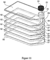
Figure 1 1 shows an exploded view of an additional embodiment of the present invention depicted inFigure 10 . -
Figure 12a shows a side view of the embodiment of the present invention depicted inFigure 1 1 .Figure 12b shows α cross-sectional view of the embodiment of fhe present invention depicted inFigure 1 1 . -
Figure 13 shows α perspective view of an additional embodiment of the present invention. -
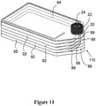
Figure 14 shows a perspective view of an additional embodiment of the present invention. -
Figure 15 shows a perspective view of an additional embodiment of the present invention filled with cell culture media. -
Figure 16a shows a perspective view of an additional embodiment of the present invention containing cell culture media equally filling the trays. -
Figure 16b shows a perspective view of the present invention depicted inFigure 15 in a tipped position in order to spread the cell culture media throughout the trays. - For the purposes of this specification and appended claims, unless otherwise indicated, all numbers expressing quantities of ingredients, percentages or proportions of materials, reaction conditions, and other numerical values used in the specification and claims, are to be understood as being modified in all instances by the term "about".
- Accordingly, unless indicated to the contrary, the numerical parameters set forth in the following specification and attached claims are approximations that may vary depending upon the desired properties sought to be obtained by the present invention. At the very least, and not as an attempt to limit the application of the doctrine of equivalents to the scope of the claims, each numerical parameter should at least be construed in light of the number of reported significant digits and by applying ordinary rounding techniques.
- Notwithstanding that the numerical ranges and parameters setting forth the broad scope of the invention are approximations, the numerical values set forth in the specific examples are reported as precisely as possible. Any numerical value, however, inherently contains certain errors necessarily resulting from the standard deviation found in their respective testing measurements. Moreover, all ranges disclosed herein are to be understood to encompass any and all subranges subsumed therein. For example, a range of "1 to 10" includes any and all subranges between (and including) the minimum value of 1 and the maximum value of 10, that is, any and all subranges having a minimum value of equal to or greater than 1 and a maximum value of equal to or less than 10, e.g., 5.5 to 10.
- As used herein, the singular forms "a," "an," and "the" include plural referents unless the context clearly dictates otherwise.
-
Figure 1 shows an embodiment of the present invention, whereinflask 2 preferably comprises a transparent, translucent or nontransparent glass or plastic material. Theflask 2 has atop wall 4, abottom wall 6 and three or more sidewalls 8 which extend substantially perpendicular to and between thetop wall 4 and thebottom wall 6 to define aninterior space 10. As shown thebottom wall 6 andsidewalls 8 are formed as one piece. They may if desired be formed of individual pieces if desired.Top wall 4 is liquid tightly sealed to theupper edge 12 of thesidewalls 8 such as by heat bonding, melt bonding, sonic vibration welding or adhesives. Optionally as in this embodiment, theupper edge 12 of the sidewalls has a feature, in this case aridge 14 that mates with a corresponding feature in this case atrough 16 in the bottom orinner surface 18 of thetop wall 4 so that the walls are properly aligned and sealed together. If the top wall is desired to be removal thetop wall 4 can be secured to thesidewalls 8 by other well-known means such as screws, clamps, sliding dovetails and the like (not shown). - The
top wall 4 has aport 20 that can be selectively opened and closed. One such means for selectively opening and closing theport 20 is acap 22 which can and preferably has avent 24 that allows for the transfer of gases into and out of the interior 10 without contamination. This can be accomplished by using a frit, metal such as stainless steel or plastic such as a POREX® frit or a hydrophobic membrane or filter, all of which have a pore size designed to keep out bacteria, dust and other such contaminants. A typical pore size used in such a frit or filter or membrane is less than about 0.65 micron, preferably less than about 0.4 micron and more preferably about 0.22 micron. - As shown the
bottom wall 6 in this embodiment has a first substantiallyflat portion 24 and a second substantiallyflat portion 26 connected to each other by a substantially planar interconnectingportion 28 that is on an angle so as to connect the twoportions first portion 24 is at one desired horizontal plane that is below that second horizontal plane of thesecond portion 26. This means that when in its use position as shown inFigure 1 , thefirst portion 24 is the lowermost portion of the interior 10 of thedevice 2. - A portion of the interior 10 contains one or more
cell growing trays 30. These trays have a substantially flat bottom 32 andsidewalls 34 that run around the periphery of thetray 30. The number ofsidewalls 34 of the tray(s) 30 is equal in number to the number of sidewalls of theflask 2. Thefront sidewall 36 of the tray(s) is different than the rest of thesidewalls 34 of the tray(s) 30 in that it is at upward angle away from the substantiallyflat bottom 32 of eachtray 30. Thefront sidewall 36 or lip provides open access to each tray for cells, liquids and gases when they are arranged within theflask 2. Also shown on eachtray 30 is anoptional feature 38 which is a foot that extends outwardly from thefront sidewall 36 of eachtray 30. - The bottom walls extend a distance from the outside bottom planar surface to form a perimeter skirt. The perimeter skirt forms a linear transition to the end wall. The linear skirt transition creates an angle that when the culture system is in position the transitional skirt flat onto a work surface all the internal plane portions (one, two, three and four) are positioned at a positive angle so that liquid on those surfaces will drain toward the access port end of the culture system. The feature enables full recovery of spent media during media changes and complete recovery of the cells post culture.
- The tray(s) 30 are spaced about the
bottom wall 6 of theflask 2 so that theinner surface 44 of the bottom wall acts as a tray. In this embodiment the tray(s) are spaced from thebottom surface 44 by detents formed on theopposite sidewalls 8. These detents or rests extend outwardly into the interior 10 to an extent sufficient to support the tray(s) in the interior 10. Typically they can extend outwardly from the sidewalls into the space by a distance of from about 3 mm to about 7 mm. Alternatively, thebottommost tray 30 may have feet (not shown) formed on itsbottom surface 32 to provide the necessary spacing with theinner bottom surface 44 of the interior 10. In another embodiment if thebottom surface 44 is not desired as a cell growth layer, no detent or feet are needed and the tray(s) bottom 32 may contact thebottom surface 44. - Preferably, the tray(s) 30 are simply stacked onto of each other and retained in the flask by the spacing considerations, making them narrow enough so that the tray(s) 30 once inserted cannot disassociate from each other. Optionally, they may be sealed to each other such as by the use of adhesives or heat bonding and the like, or they may have a strap such as one or more tie wraps or cable wraps (not shown) placed around them, or they may contain sliding dovetails or snap fits (not shown) between their adjacent surfaces to hold them together.
- The angle of the interconnecting
portion 28 is equal to or greater than the angle of thefront sidewall 36 of eachtray 30 so that when moved to its loading/unloading position as described inFigure 2 the liquid and cells can flow to their appropriate locations. Typically, the angle of the interconnectingportion 28 is from about 10 degrees to about 60 degrees as measured by theangle alpha 46 between the first plane of thefirst portion 24 and theouter bottom surface 48 of the interconnectingportion 28. Preferably theangle alpha 46 is between about 10 degrees and about 45 degrees, more preferably from about 15 degrees to about 30 degrees and most preferably about 22 degrees. The angle of thefront sidewall 36 as described above is equal theangle alpha 46 or less than theangle alpha 46 but preferably is never greater than theangle alpha 46. Additionally,top wall 4 may optionally have a similar third portion 29 (as shown) that corresponds to the angle alpha in a position directly above the interface between thefirst portion 24 and the interconnectingportion 28 of thebottom wall 6. This is a preferred option so that the space between the top tray and the inner surface of thetop wall 4 is the same as the space between any other tray (if more than one is used) and the adjacent surface above it (the bottom surface of the tray above it for example). Alternatively thetop wall 4 may be substantially planar across its length and the space between the top tray and the top wall can be suitably enlarged if necessary to provide suitable flow of liquids and gases into that tray (not shown) - The tray(s) 30 are contained within the interior 10 to the area circumscribed by the
first portion 24 and preferably at least a portion of the interconnectingportion 28 of thebottom wall 6. This leaves anopen area 41 in the interior 10 around and adjacent to theport 20 for the entrance and exit of liquids, cells and gases. In the embodiment where the tray(s) 30 are not bonded or otherwise secured to the bottom orsidewalls flask 2, foot 38 acts as a means for preventing the tray(s) from moving into theopen area 41 when the flask is tilted for unloading or if desired for loading as well. -
Figure 2 shows theflask 2 when in its unloading position. This may also be the loading position as desired. As shown, theflask 2 is lifted at its rear 50 and tilted forward on itsfoot 42 that extends downwardly from thesidewall 8 adjacent theport 20. A pipette or syringe or funnel (pipette 52 is shown) can be inserted into theport 20 and have access to theopen area 41 of the interior 10. Thesecond portion 26 when in the unloading optionally loading position becomes the low point of theflask 2. This allows one to easily recover cells or exchange media or add new media or cells into theopen area 41 without disturbing the tray(s) or requiring one to tip the flask vertically as is required by the prior art. -
Figure 3 shows απ alternative embodiment of the design ofFigures 1 and2 . In this embodiment, the second portion becomes a part of the interconnectingportion 28 such that there is a flat first portion of thebottom 6 and only anangled interconnecting potion 28 that meets and terminates in thefront sidewall 54. Thesecond portion 26 in effect becomes the point at which the interconnectingportion 28 meets thefront sidewall 54. Thedevice 2 is used the same way as described inFigure 2 . All elements common toFigures 1 and3 retain the same reference numbers, perform the same functions, and have the same attributes as described in reference to the embodiment ofFigure 1 . -
Figure 4 shows a series offlasks 2 according to the present invention. Due to their design with the relatively flatbottom portions 24 andtop wall 4 they can be alternately stacked on top of each other to save floor or hood space during incubation and growth. - As previously described the flask may have three or more sidewalls 8.
Figures 5A-D show three different sidewall examples of theflask 2 to illustrate this feature.Figure 5A shows a triangular-shapedflask 2 having three sidewalls 8A.Figure 5B shows a polygonal sidewall configuration of four more sidewalls with sidewalls 8B and 8D being linear or straight sidewalls and sidewalls 8C being angle or tapered or curved sidewalls.Sidewalls 8c may be an extension of sidewalls 8B in which case there are 3 sidewalls or they may be separate sidewall portions in which the flask has 5 sidewalls.Figure 5C shows a rectangular-shaped design with four sidewalls 8D-8G.Figure 5D shows another design with five sidewalls 8I-8M.Figure 5E shows a single circular sidewall 8N. - The culture system of the invention, when in use, includes a flask filled and/or emptied by a pipette, syringe or similar device, having the culture system positioned on a work surface and having the threaded opening in an upward position. The researcher dispenses the media and cells into the system. The media amount can vary depending on the cell type being cultured, i.e., more media for highly metabolic cells such as stem cells. The researcher seals the system with a gas permeable closure, such as a threaded cap with a hydrophobic bacterial retentive microporous matrix enabling free exchange of gas from outside of the system to the inside. The culture system is tipped to its side, so that the media freely fills the layers insuring a uniform amount between each tray. The system is tipped on to the side wall opposite the closure then tipped forward, resulting in the culture system seated with the first and third portion surfaces substantially planar to the work surface. In this position the media and cells spread uniformly across each culture layer and the first portion surface. This readied culture system is typically placed into an environmental controlled chamber, incubation, for the cell growth phase.
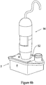
- The researcher needs to periodically investigate the status of the culture during the growth phase. This activity typically consists of the culture system being removed from the incubator and transported to a microscope that may or may not be in close proximity. As shown in
Figures 6A and6B ,flask 2 additionally includes alens 54 that may be molded in the top wall or the bottom walls (not shown) with the focal surface being the first adjacent culture layer. Ideally, the magnification from this lens is 10x to 40x for low level viewing of the cell culture. Preferably, the magnification is 25x to 40x so that visualization of cell growth status and cell detachment during cell recovery is visible with the naked eye. Additionally, acamera system 56 such as the Dino-Lite system (BigC.com Corp., Torrance, Ca) can be secured via a coupling mechanism or mountingsystem 52 to thetop wall 4 or the bottom wall (not shown) to provide image capture. Ideally, this configuration is maintained within the incubator such that monitoring can occur without a researcher having to enter the incubator and disrupt the growth phase of the cells. Additionally, the use of a wireless connection permits the remote monitoring of the cell culture (not shown). - As shown in
Figure 7 ,flask 2 may also include one or more of the following features a) an overmoldedseal plastic seal 57 around the perimeter of the flask; b) a non-skid, preferably plastic,button 55 to secure theflask 2 from slipping during the recovery of spent media, cell post cultures or the like when the flask is tipped; c) overmolded plastic ribs or other such feature that provides a user with a non-slip gripping or handling surface. In a preferred embodiment, the plastic used to make these features comprises a thermoplastic elastomer (TPE) with a hard durometer greater than 49 shore A in order to provide the user an appropriate tactile feel for gripping or otherwise handling the flask. - As shown in
Figure 8 ,flask 2 may also include an easy to open tear-awayelement 60 or the like in one of thesidewalls 8, wherein the easy to open tear- awayelement 60 is preferably a component of theovermolded seal 57. - As shown in
Figures 9 and10 , a multitier cell cultivatingmultitier flask 100 comprising acover 94 including atop plate 98,side walls 96 and aresealable port 20; anintermediate tray 92 tor receiving cells and acell culture media 105, the intermediate tray having abottom plate 95,side walls 97, and agap region 89 formed between an interior upwardlyangled lip 78 having a swooping curvilinearinterior edge 99 located on an interior portion of the bottom plate and an adjacent outwardlyangled side wall 87 of the bottom plate; and abase tray 90 for receiving cells and a cell culture media, including abottom plate 93 andside walls 91 , wherein the tray is positioned between the cover and the base tray, such that the gap region of the bottom plate of the tray is in alignment with the port located on the cover, resulting in the cover, the tray and the base tray in fluid communication with one another which enables a user to directly access each of the cell media located on the tray and the base tray. - As depicted in
Figs. 9 to 16 , acell cultivating flask 100 includes acover 94 having atop plate 98, one ormore side walls 96 and aresealable port 20; a plurality ofintermediate trays 92 for receiving cells and acell culture media 105, eachintermediate tray 92 having abottom plate 95, one ormore side walls 97, and agap region 89 formed between an interior upwardlyangled lip 78 having a swooping curvilinearinterior edge 99 located on an interior portion of the bottom plate and an adjacent outwardlyangled side wall 87 of the bottom plate; and abase tray 90 for receiving cells and a cell culture media, having abottom plate 93 and one ormore side walls 91. The plurality ofintermediate trays 92 are positioned between thecover 94 and thebase tray 90, such that the plurality of intermediate trays are stacked on top of one another, and the gap regions of thebottom plates 95 of each intermediate tray are in alignment with each other and with the port located on the cover, resulting in the port, the plurality of intermediate trays and the base tray in fluid communication with one another which enables a user to directly access each of the cell media located on the plurality of intermediate trays and base tray, with a standard pipetting device and the like. - As shown in
Fig. 13 , theside walls 97 on eachintermediate tray 92 stacked on top of one another are preferably fused to form a liquidtight seal 135, to the underside of theside walls 97 on next adjoining intermediate tray. The side walls on each intermediate tray stacked on top of one another are ultrasonically welded 135 to the underside of the side walls of the next adjoiningintermediate tray 92; the side wall of theintermediate tray 92 adjacent thecover 94 is ultrasonically welded 145 to the underside of the side wall of thecover 94, and the side wall of thebase tray 90 is ultrasonically welded 155 to the underside of the side wall of the adjoiningintermediate tray 92. - The
resealable port 20 can be selectively opened and closed. One such means for selectively opening and closing theport 20 is acap 22, which can be threaded and preferably has avent 24 that allows for the transfer of gases into and out of the interior 10 without contamination. This can be accomplished by using a frit, metal such as stainless steel or plastic such as a POREX® frit or a hydrophobic membrane or filter, all of which have a pore size designed to keep out bacteria, dust and other such contaminants. A typical pore size used in such a frit or filter or membrane is less than about 0.65 micron, preferably less than about 0.4 micron and more preferably about 0.22 micron. - As shown in
Figs. 9 to 16 , a multitiercell cultivating flask bottom wall 88 of abase tray 90 having a first substantiallyflat portion 86 and a second substantiallyflat portion 84 connected to each other by a substantially planar interconnectingportion 81 that is on an angle so as to connect theportions - As depicted in
Figs. 12a and 12b ,base tray 90 includesfirst portion 86 configured as a substantially horizontal plane that is below the second substantially horizontal plane of thesecond portion 84 such that media, cells and the like 105 will evenly disperse along the upper surface ofbase tray 90 becauseangled portion 81 prevents cells andmedia 105 from pooling onportion 84. When theflask 110 is in use as depicted inFigs. 12a, 12b and15 ,first portion 86 ofbase tray 90 is the lowermost portion of theinterior 120 of thedevice 110. - As depicted in
Figs. 16a and 16b , whenflask 110 is placed on one side as shown inFig. 16a each tray equally fills withmedia 105. Alternatively, whenflask 110 is placed in an upright position as shown inFig. 16b , each tray equally fills withmedia 105 again. - As shown in
Figs. 10 ,12a and 12b , a portion of the interior 120 contains one or morecell growing trays 92. These trays have a substantiallyflat bottom portion 76, a substantiallyplanar lip portion 78 that is on an upward angle away from the substantiallyflat bottom 76 of eachtray 92, and sidewalls 97 that run around the periphery of thetray 92. Thelip portion 78 has aninterior edge portion 99. The number ofsidewalls 97 of the tray(s) 92 is equal in number to the number of sidewalls of theflask 110. Thefront sidewall 87 of the tray(s) is different than the rest of thesidewalls 97 of the tray(s) 92 in that it is angled outward and away from the interior swoopingcurvilinear edge 99 of thelip 78 of the bottom portion of the trays. Thefront sidewall 87 and the interiorcurvilinear edge 99 of thelip portion 78 provides open access or agap region 89 to each tray for cells, liquids andgases 105 when arranged within theflask 110.
Claims (14)
- A cell cultivating flask (2;100;110;115) comprising:a cover (94) including a top plate (98), a side wall (96) and a resealable port (20);one or more intermediate tray(s) (30;92) for receiving cells and cell media, each intermediate tray (30;92) having a bottom plate (95), an underside, an upperside, a side wall (97), and a gap region (89) formed between an interior upwardly angled lip (36;78) having an edge (99) located on an interior portion of the bottom plate (95) and an adjacent side wall portion (87) of the bottom plate (95); anda base tray (90) for receiving cells and cell media, the base tray (90) including a bottom plate (93), an upperside and a side wall (91), wherein the bottom plate (93) has a first substantially flat portion (24;86), a second substantially flat portion (26;84) located above the plane of the first flat portion (24;86) and connected to the first flat portion (24;86) by an interconnecting portion (28;81) that is at an angle so as to connect the first and second flat portions (24,26;86,84) together,wherein the intermediate tray(s) (30;92) is/are positioned between the cover (94) and the base tray (90), and the gap region(s) (89) of the intermediate tray(s) (30;92) and the second flat portion (26;84) of the base tray (90) are in alignment with the port (20) on the cover (94), resulting in the port (20), the intermediate tray(s) (30;92) and the base tray (90) in fluid communication with one another providing direct access to cells and cell media when located on each of the intermediate and base trays (30;92,90).
- The flask (2;110) of claim 1, wherein a plurality of intermediate trays (30;92) are stacked on top of one another, and the gap regions (89) of each intermediate tray (30;92) are in alignment with each other, and with the port (20) on the cover (94).
- The flask (110) of claim 2, wherein the side wall (97) on each intermediate tray (92) stacked on top of one another is fused by a liquid tight seal or bond (135) to the underside of the next adjoining intermediate tray (92).
- The flask (110) of claim 3, wherein the side wall (97) of the intermediate tray (92) adjacent the cover (94) is fused by a liquid tight seal or bond (145) to the underside of the cover (94), and the side wall (91) of the base tray (90) is fused by a liquid tight seal or bond (155) to the underside of the adjoining intermediate tray (92).
- The flask (110) of claim 3 or 4, wherein the liquid tight seal (135,145,155) is formed by an ultrasonic weld.
- The flask (2;100;110;115) of any one of claims 1 to 5, wherein the resealable port (20) comprises a threaded cap (22) .
- The flask (2;100;110;115) of claim 6, wherein the threaded cap (22) includes a vent (24), preferably in the form of an air permeable fabric, in communication with an interior space of the flask (2;100;110;115).
- The flask (2;100;110;115) of claim 7, wherein the vent (24) is a frit or filter of membrane with a pore size of less than about 0.65 micron, preferably less than about 0.4 micron, preferably less than about 0.22 micron, preferably about 0.22 micron.
- The flask (2;100;110;115) of any one of claims 1 to 8, wherein a pipette like device or syringe can be used to add or remove cells and cell cultivating media from the intermediate or base trays through the port (20).
- The flask (2;100;110;115) of any one of claims 1 to 9, wherein the flask (100;110;115) is made from a material selected from the group consisting of a polymer, glass or combination thereof.
- The flask (2;100;110;115) of claim 10, wherein the material is transparent, translucent, opaque, a single color, multicolored or combinations thereof.
- The flask (2;100;110;115) of any one of claims 1 to 11, wherein the angle of the interconnecting portion (28;81) is equal to or greater than the angle of the upwardly angled lip (36;78) of the bottom plate (95) of the intermediate tray(s) (30;92).
- The flask (2;100;110;115) of any one of claims 1 to 12, wherein the angle of the interconnecting portion (28;81) is from about 10 degrees to about 60 degrees, preferably from about 10 degrees to about 45 degrees, preferably from about 15 degrees to about 30 degrees, preferably 22 degrees.
- A method of using a multitier cell culture flask comprising:a) providing a cell cultivating flask (2;100;110;115) according to any one of claims 1 to 13;b) providing cells and cell media (105);c) adding the cells and cell media (105) to the flask (100;110;115) through the port (20) by a pipette-like device or a syringe;d) growing the cells in the flask (100;110;115) for a desired amount of time and under desired conditions, ande) removing the cells and/or media from the flask (100;110;115) through the port (20) via a pipette-like device or a syringe.
Applications Claiming Priority (3)
| Application Number | Priority Date | Filing Date | Title |
|---|---|---|---|
| US13498508P | 2008-07-16 | 2008-07-16 | |
| US20768309P | 2009-02-14 | 2009-02-14 | |
| PCT/US2009/004118 WO2010008566A2 (en) | 2008-07-16 | 2009-07-16 | A single or multitier cell culture system |
Publications (2)
| Publication Number | Publication Date |
|---|---|
| EP2304019A2 EP2304019A2 (en) | 2011-04-06 |
| EP2304019B1 true EP2304019B1 (en) | 2019-04-10 |
Family
ID=41550918
Family Applications (1)
| Application Number | Title | Priority Date | Filing Date |
|---|---|---|---|
| EP09788926.5A Active EP2304019B1 (en) | 2008-07-16 | 2009-07-16 | A multitier cell culture system |
Country Status (6)
| Country | Link |
|---|---|
| US (1) | US9783769B2 (en) |
| EP (1) | EP2304019B1 (en) |
| JP (1) | JP5175396B2 (en) |
| CN (1) | CN102099459B (en) |
| ES (1) | ES2733631T3 (en) |
| WO (1) | WO2010008566A2 (en) |
Families Citing this family (44)
| Publication number | Priority date | Publication date | Assignee | Title |
|---|---|---|---|---|
| US8778669B2 (en) | 2009-07-22 | 2014-07-15 | Corning Incorporated | Multilayer tissue culture vessel |
| SG10201703990WA (en) | 2010-01-20 | 2017-06-29 | Emd Millipore Corp | Cell image capturing and remote monitoring systems |
| CN108410733A (en) * | 2010-10-12 | 2018-08-17 | 纳格·南科国际有限公司 | Cell culture apparatus |
| MX2013004170A (en) | 2010-10-12 | 2013-06-28 | Nalge Nunc Int Corp | Ventable closure with port. |
| NL2007734C2 (en) * | 2011-11-07 | 2013-05-08 | Tulip Life Science Products B V | DEVICE FOR GROWING CELLS. |
| US9417229B2 (en) * | 2011-12-20 | 2016-08-16 | Ascensia Diabetes Care Holdings Ag | Linear, cartridge-based glucose measurement system |
| EP2809770A1 (en) * | 2012-02-02 | 2014-12-10 | Corning Incorporated | Cell culture systems |
| US9383333B2 (en) | 2012-05-31 | 2016-07-05 | Ascensia Diabetes Care Holdings Ag | Replaceable multistrip cartridge and biosensor meter |
| CA2873410C (en) | 2012-05-31 | 2017-10-03 | Bayer Healthcare Llc | Multistrip cartridge |
| IN2015DN02120A (en) * | 2012-09-18 | 2015-08-14 | Bayer Technology Services Gmbh | |
| CN102864076A (en) * | 2012-09-26 | 2013-01-09 | 无锡耐思生物科技有限公司 | Cell culture bottle structure |
| US20140120607A1 (en) * | 2012-10-26 | 2014-05-01 | Corning Incorporated | Multi-Layered Cell Culture Vessel |
| US9005550B2 (en) | 2012-10-29 | 2015-04-14 | Corning Incorporated | Multi-layered cell culture vessel with manifold grips |
| CN105209908B (en) | 2013-03-12 | 2018-01-09 | 安晟信医疗科技控股公司 | With the test-strips gauge for push to test bar against the mechanism of optical reader |
| US9790465B2 (en) | 2013-04-30 | 2017-10-17 | Corning Incorporated | Spheroid cell culture well article and methods thereof |
| JP6307802B2 (en) * | 2013-07-05 | 2018-04-11 | 株式会社Ihi | Culture vessel |
| JP2015050964A (en) * | 2013-09-06 | 2015-03-19 | 住友ベークライト株式会社 | Multistage culture flask and production method of cell culture flask |
| JP2016077186A (en) * | 2014-10-14 | 2016-05-16 | 大日本印刷株式会社 | Culture container and lower container thereof |
| CN113481097A (en) | 2014-10-29 | 2021-10-08 | 康宁股份有限公司 | Perfusion bioreactor platform |
| WO2017025584A1 (en) * | 2015-08-12 | 2017-02-16 | Cytovac A/S | A cell cultivation method, a cell cultivation vessel, and uses thereof |
| US11299699B2 (en) | 2015-11-06 | 2022-04-12 | Nihon University | Culture container |
| CN106222089B (en) * | 2016-08-22 | 2018-09-21 | 王铁苗 | A kind of experiment auxiliary culture apparatus |
| CN106047703B (en) * | 2016-08-22 | 2018-08-10 | 青岛爱博生物科技有限公司 | A kind of test sample culture apparatus |
| CN106467893B (en) * | 2016-08-22 | 2018-07-24 | 王铁苗 | A kind of experiment auxiliary device |
| CN106282017B (en) * | 2016-08-22 | 2018-09-21 | 王铁苗 | A kind of integrated form sample culture apparatus |
| CN106222087B (en) * | 2016-08-22 | 2018-07-24 | 王铁苗 | A kind of sample culture carrier |
| CN106222090B (en) * | 2016-08-22 | 2018-07-24 | 王铁苗 | A kind of experiment assistant carrier |
| CN106190843B (en) * | 2016-08-22 | 2018-06-15 | 刘力伟 | A kind of multisample culture apparatus |
| CN106244457B (en) * | 2016-08-22 | 2018-08-03 | 日照安维信生物科技有限公司 | A kind of experiment culture carrier structure |
| WO2019014610A1 (en) | 2017-07-14 | 2019-01-17 | Corning Incorporated | Cell culture vessel for 3d culture and methods of culturing 3d cells |
| US11857970B2 (en) | 2017-07-14 | 2024-01-02 | Corning Incorporated | Cell culture vessel |
| EP3652289A1 (en) * | 2017-07-14 | 2020-05-20 | Corning Incorporated | Handling features for microcavity cell culture vessel |
| CN111065729A (en) | 2017-07-14 | 2020-04-24 | 康宁股份有限公司 | Cell culture container |
| EP3652290B1 (en) | 2017-07-14 | 2022-05-04 | Corning Incorporated | 3d cell culture vessels for manual or automatic media exchange |
| US11866683B2 (en) | 2017-11-06 | 2024-01-09 | Corning Incorporated | Cell culture apparatuses with manifolds including column structures |
| EP3649229B1 (en) | 2018-07-13 | 2021-08-25 | Corning Incorporated | Cell culture vessels with stabilizer devices |
| CN111065725B (en) | 2018-07-13 | 2024-03-29 | 康宁股份有限公司 | Fluidic device comprising microplates with interconnected walls |
| EP3649226B1 (en) * | 2018-07-13 | 2022-04-06 | Corning Incorporated | Microcavity dishes with sidewall including liquid medium delivery surface |
| CN109207363A (en) * | 2018-09-20 | 2019-01-15 | 南京至泰生物医药科技有限公司 | Laminar-flow type living cells culture device |
| USD907244S1 (en) | 2019-06-14 | 2021-01-05 | Emd Millipore Corporation | Cell imager |
| JP2020202784A (en) * | 2019-06-17 | 2020-12-24 | シンフォニアテクノロジー株式会社 | Multi-layered culture vessel |
| US20220290084A1 (en) | 2019-07-08 | 2022-09-15 | Nipro Corporation | Multilayer Culture Vessel |
| EP4004180A4 (en) * | 2019-07-29 | 2023-09-06 | VitroLabs Inc | Scalable bioreactor systems and methods for tissue engineering |
| KR102411446B1 (en) * | 2019-10-17 | 2022-06-23 | 주식회사 아모그린텍 | Cell culture device |
Citations (1)
| Publication number | Priority date | Publication date | Assignee | Title |
|---|---|---|---|---|
| US20070065933A1 (en) * | 2003-02-28 | 2007-03-22 | Peter Esser | Tray stack adapted for active gassing |
Family Cites Families (21)
| Publication number | Priority date | Publication date | Assignee | Title |
|---|---|---|---|---|
| US4228243A (en) * | 1978-07-13 | 1980-10-14 | Toray Industries, Inc. | Cell culture propagation apparatus |
| US5139952A (en) | 1983-09-16 | 1992-08-18 | Terumo Corporation | Tissue culture flask |
| US4770854A (en) * | 1986-02-03 | 1988-09-13 | Costar Corporation | Laboratory flask |
| US4734373A (en) | 1986-06-24 | 1988-03-29 | Bartal Arie H | Apparatus for enhancing cell growth, preservation and transport |
| EP0500549B1 (en) * | 1990-09-19 | 1996-05-08 | BERRY, Eric, Scott | Continuous high-density cell culture system |
| JPH04262775A (en) * | 1990-10-18 | 1992-09-18 | Costar Corp | Continuous cell cultivating device |
| US5310676A (en) | 1991-11-15 | 1994-05-10 | A/S Nunc | Cell cultivating device |
| US5695987A (en) | 1996-08-08 | 1997-12-09 | Becton Dickinson And Company | Reusable vented flask cap cover |
| WO1998010055A1 (en) * | 1996-09-03 | 1998-03-12 | Kaneka Corporation | Method for inducing immunosuppressive cells and culturing device to be used therefor |
| US5783440A (en) * | 1996-09-30 | 1998-07-21 | Becton Dickinson And Company | Culture vessel |
| US6107085A (en) * | 1997-07-11 | 2000-08-22 | Corning Incorporated | Self contained cell growth system |
| US6569675B2 (en) * | 2000-06-16 | 2003-05-27 | Corning Incorporated | Cell cultivating flask and method for using the cell cultivating flask |
| CN103173354B (en) * | 2003-10-08 | 2017-07-14 | 威尔森沃尔夫制造公司 | The method and device of cell culture is carried out using poromeric material |
| EP1863897A1 (en) | 2005-03-14 | 2007-12-12 | Corning Inc. | Cell cultivating flask |
| EP1862533B1 (en) * | 2005-03-22 | 2015-05-13 | Medinet., Co. Ltd. | Cell culture estimating system, method of cell culture estimation and cell culture estimating program |
| US7745209B2 (en) * | 2005-07-26 | 2010-06-29 | Corning Incorporated | Multilayered cell culture apparatus |
| EP1963479A4 (en) * | 2005-08-01 | 2010-06-02 | Life Technologies Corp | Labels, containers, system and methods for providing reagents |
| US20080118974A1 (en) | 2006-11-20 | 2008-05-22 | Gregory Roger Martin | Large scale cell culture vessel |
| US7897379B2 (en) * | 2007-02-26 | 2011-03-01 | Corning Incorporated | Device and method for reducing bubble formation in cell culture |
| WO2009017765A1 (en) * | 2007-07-30 | 2009-02-05 | Peter Florez | Disposable mini-bioreactor device and method |
| EP2311184A4 (en) | 2008-07-18 | 2014-02-26 | Peregrine Semiconductor Corp | Low-noise high efficiency bias generation circuits and method |
-
2009
- 2009-07-16 WO PCT/US2009/004118 patent/WO2010008566A2/en active Application Filing
- 2009-07-16 JP JP2011518730A patent/JP5175396B2/en active Active
- 2009-07-16 EP EP09788926.5A patent/EP2304019B1/en active Active
- 2009-07-16 ES ES09788926T patent/ES2733631T3/en active Active
- 2009-07-16 US US12/460,265 patent/US9783769B2/en active Active
- 2009-07-16 CN CN2009801280863A patent/CN102099459B/en active Active
Patent Citations (1)
| Publication number | Priority date | Publication date | Assignee | Title |
|---|---|---|---|---|
| US20070065933A1 (en) * | 2003-02-28 | 2007-03-22 | Peter Esser | Tray stack adapted for active gassing |
Also Published As
| Publication number | Publication date |
|---|---|
| JP2011528226A (en) | 2011-11-17 |
| US20100129900A1 (en) | 2010-05-27 |
| CN102099459B (en) | 2013-05-01 |
| ES2733631T3 (en) | 2019-12-02 |
| US20160137961A2 (en) | 2016-05-19 |
| EP2304019A2 (en) | 2011-04-06 |
| WO2010008566A2 (en) | 2010-01-21 |
| JP5175396B2 (en) | 2013-04-03 |
| CN102099459A (en) | 2011-06-15 |
| WO2010008566A3 (en) | 2010-05-27 |
| US9783769B2 (en) | 2017-10-10 |
Similar Documents
| Publication | Publication Date | Title |
|---|---|---|
| EP2304019B1 (en) | A multitier cell culture system | |
| US7897379B2 (en) | Device and method for reducing bubble formation in cell culture | |
| CA2551940C (en) | Containers and methods for the automated handling of a liquid | |
| JP5852048B2 (en) | Multi-layer cell culture system with limited access | |
| JP5107919B2 (en) | Multi-layer cell culture device | |
| US8323957B2 (en) | Device and method for the incubation of cells | |
| US8658422B2 (en) | Culture plate comprising a lid for lateral ventilation | |
| US20080003671A1 (en) | Fluid flow diverter for cell culture vessel | |
| EP0800571A2 (en) | Biological analysis device having improved contamination prevention | |
| JP2011501689A (en) | Microreactor | |
| EP3148700A1 (en) | Single column microplate system and carrier for analysis of biological samples | |
| JP2007187666A5 (en) | ||
| JPS60102184A (en) | Culture flask | |
| EP3998329A1 (en) | Multilayer culture vessel | |
| US20090246087A1 (en) | Microtiter plate for long-term storage | |
| JP2005502571A (en) | Reaction vessel to create sample | |
| CN220552863U (en) | Antibody incubation tube for WB experiment | |
| US20230302455A1 (en) | Container for diagnostic assays | |
| US20150315536A1 (en) | Cell cultivating flask |
Legal Events
| Date | Code | Title | Description |
|---|---|---|---|
| PUAI | Public reference made under article 153(3) epc to a published international application that has entered the european phase |
Free format text: ORIGINAL CODE: 0009012 |
|
| 17P | Request for examination filed |
Effective date: 20110114 |
|
| AK | Designated contracting states |
Kind code of ref document: A2 Designated state(s): AT BE BG CH CY CZ DE DK EE ES FI FR GB GR HR HU IE IS IT LI LT LU LV MC MK MT NL NO PL PT RO SE SI SK SM TR |
|
| AX | Request for extension of the european patent |
Extension state: AL BA RS |
|
| DAX | Request for extension of the european patent (deleted) | ||
| RAP1 | Party data changed (applicant data changed or rights of an application transferred) |
Owner name: EMD MILLIPORE CORPORATION |
|
| 17Q | First examination report despatched |
Effective date: 20160607 |
|
| GRAP | Despatch of communication of intention to grant a patent |
Free format text: ORIGINAL CODE: EPIDOSNIGR1 |
|
| STAA | Information on the status of an ep patent application or granted ep patent |
Free format text: STATUS: GRANT OF PATENT IS INTENDED |
|
| INTG | Intention to grant announced |
Effective date: 20181018 |
|
| GRAS | Grant fee paid |
Free format text: ORIGINAL CODE: EPIDOSNIGR3 |
|
| GRAA | (expected) grant |
Free format text: ORIGINAL CODE: 0009210 |
|
| STAA | Information on the status of an ep patent application or granted ep patent |
Free format text: STATUS: THE PATENT HAS BEEN GRANTED |
|
| AK | Designated contracting states |
Kind code of ref document: B1 Designated state(s): AT BE BG CH CY CZ DE DK EE ES FI FR GB GR HR HU IE IS IT LI LT LU LV MC MK MT NL NO PL PT RO SE SI SK SM TR |
|
| REG | Reference to a national code |
Ref country code: GB Ref legal event code: FG4D |
|
| REG | Reference to a national code |
Ref country code: CH Ref legal event code: EP Ref country code: AT Ref legal event code: REF Ref document number: 1118644 Country of ref document: AT Kind code of ref document: T Effective date: 20190415 |
|
| REG | Reference to a national code |
Ref country code: CH Ref legal event code: NV Representative=s name: E. BLUM AND CO. AG PATENT- UND MARKENANWAELTE , CH |
|
| REG | Reference to a national code |
Ref country code: IE Ref legal event code: FG4D |
|
| REG | Reference to a national code |
Ref country code: DE Ref legal event code: R096 Ref document number: 602009057853 Country of ref document: DE |
|
| REG | Reference to a national code |
Ref country code: NL Ref legal event code: FP |
|
| REG | Reference to a national code |
Ref country code: LT Ref legal event code: MG4D |
|
| REG | Reference to a national code |
Ref country code: AT Ref legal event code: MK05 Ref document number: 1118644 Country of ref document: AT Kind code of ref document: T Effective date: 20190410 |
|
| PG25 | Lapsed in a contracting state [announced via postgrant information from national office to epo] |
Ref country code: HR Free format text: LAPSE BECAUSE OF FAILURE TO SUBMIT A TRANSLATION OF THE DESCRIPTION OR TO PAY THE FEE WITHIN THE PRESCRIBED TIME-LIMIT Effective date: 20190410 Ref country code: LT Free format text: LAPSE BECAUSE OF FAILURE TO SUBMIT A TRANSLATION OF THE DESCRIPTION OR TO PAY THE FEE WITHIN THE PRESCRIBED TIME-LIMIT Effective date: 20190410 Ref country code: NO Free format text: LAPSE BECAUSE OF FAILURE TO SUBMIT A TRANSLATION OF THE DESCRIPTION OR TO PAY THE FEE WITHIN THE PRESCRIBED TIME-LIMIT Effective date: 20190710 Ref country code: FI Free format text: LAPSE BECAUSE OF FAILURE TO SUBMIT A TRANSLATION OF THE DESCRIPTION OR TO PAY THE FEE WITHIN THE PRESCRIBED TIME-LIMIT Effective date: 20190410 Ref country code: PT Free format text: LAPSE BECAUSE OF FAILURE TO SUBMIT A TRANSLATION OF THE DESCRIPTION OR TO PAY THE FEE WITHIN THE PRESCRIBED TIME-LIMIT Effective date: 20190910 Ref country code: SE Free format text: LAPSE BECAUSE OF FAILURE TO SUBMIT A TRANSLATION OF THE DESCRIPTION OR TO PAY THE FEE WITHIN THE PRESCRIBED TIME-LIMIT Effective date: 20190410 |
|
| PG25 | Lapsed in a contracting state [announced via postgrant information from national office to epo] |
Ref country code: BG Free format text: LAPSE BECAUSE OF FAILURE TO SUBMIT A TRANSLATION OF THE DESCRIPTION OR TO PAY THE FEE WITHIN THE PRESCRIBED TIME-LIMIT Effective date: 20190710 Ref country code: LV Free format text: LAPSE BECAUSE OF FAILURE TO SUBMIT A TRANSLATION OF THE DESCRIPTION OR TO PAY THE FEE WITHIN THE PRESCRIBED TIME-LIMIT Effective date: 20190410 Ref country code: PL Free format text: LAPSE BECAUSE OF FAILURE TO SUBMIT A TRANSLATION OF THE DESCRIPTION OR TO PAY THE FEE WITHIN THE PRESCRIBED TIME-LIMIT Effective date: 20190410 Ref country code: GR Free format text: LAPSE BECAUSE OF FAILURE TO SUBMIT A TRANSLATION OF THE DESCRIPTION OR TO PAY THE FEE WITHIN THE PRESCRIBED TIME-LIMIT Effective date: 20190711 |
|
| REG | Reference to a national code |
Ref country code: ES Ref legal event code: FG2A Ref document number: 2733631 Country of ref document: ES Kind code of ref document: T3 Effective date: 20191202 |
|
| PG25 | Lapsed in a contracting state [announced via postgrant information from national office to epo] |
Ref country code: AT Free format text: LAPSE BECAUSE OF FAILURE TO SUBMIT A TRANSLATION OF THE DESCRIPTION OR TO PAY THE FEE WITHIN THE PRESCRIBED TIME-LIMIT Effective date: 20190410 Ref country code: IS Free format text: LAPSE BECAUSE OF FAILURE TO SUBMIT A TRANSLATION OF THE DESCRIPTION OR TO PAY THE FEE WITHIN THE PRESCRIBED TIME-LIMIT Effective date: 20190810 |
|
| REG | Reference to a national code |
Ref country code: DE Ref legal event code: R097 Ref document number: 602009057853 Country of ref document: DE |
|
| PG25 | Lapsed in a contracting state [announced via postgrant information from national office to epo] |
Ref country code: EE Free format text: LAPSE BECAUSE OF FAILURE TO SUBMIT A TRANSLATION OF THE DESCRIPTION OR TO PAY THE FEE WITHIN THE PRESCRIBED TIME-LIMIT Effective date: 20190410 Ref country code: DK Free format text: LAPSE BECAUSE OF FAILURE TO SUBMIT A TRANSLATION OF THE DESCRIPTION OR TO PAY THE FEE WITHIN THE PRESCRIBED TIME-LIMIT Effective date: 20190410 Ref country code: CZ Free format text: LAPSE BECAUSE OF FAILURE TO SUBMIT A TRANSLATION OF THE DESCRIPTION OR TO PAY THE FEE WITHIN THE PRESCRIBED TIME-LIMIT Effective date: 20190410 Ref country code: RO Free format text: LAPSE BECAUSE OF FAILURE TO SUBMIT A TRANSLATION OF THE DESCRIPTION OR TO PAY THE FEE WITHIN THE PRESCRIBED TIME-LIMIT Effective date: 20190410 Ref country code: SK Free format text: LAPSE BECAUSE OF FAILURE TO SUBMIT A TRANSLATION OF THE DESCRIPTION OR TO PAY THE FEE WITHIN THE PRESCRIBED TIME-LIMIT Effective date: 20190410 |
|
| PLBE | No opposition filed within time limit |
Free format text: ORIGINAL CODE: 0009261 |
|
| STAA | Information on the status of an ep patent application or granted ep patent |
Free format text: STATUS: NO OPPOSITION FILED WITHIN TIME LIMIT |
|
| PG25 | Lapsed in a contracting state [announced via postgrant information from national office to epo] |
Ref country code: SM Free format text: LAPSE BECAUSE OF FAILURE TO SUBMIT A TRANSLATION OF THE DESCRIPTION OR TO PAY THE FEE WITHIN THE PRESCRIBED TIME-LIMIT Effective date: 20190410 Ref country code: MC Free format text: LAPSE BECAUSE OF FAILURE TO SUBMIT A TRANSLATION OF THE DESCRIPTION OR TO PAY THE FEE WITHIN THE PRESCRIBED TIME-LIMIT Effective date: 20190410 |
|
| 26N | No opposition filed |
Effective date: 20200113 |
|
| PG25 | Lapsed in a contracting state [announced via postgrant information from national office to epo] |
Ref country code: TR Free format text: LAPSE BECAUSE OF FAILURE TO SUBMIT A TRANSLATION OF THE DESCRIPTION OR TO PAY THE FEE WITHIN THE PRESCRIBED TIME-LIMIT Effective date: 20190410 |
|
| PG25 | Lapsed in a contracting state [announced via postgrant information from national office to epo] |
Ref country code: LU Free format text: LAPSE BECAUSE OF NON-PAYMENT OF DUE FEES Effective date: 20190716 Ref country code: SI Free format text: LAPSE BECAUSE OF FAILURE TO SUBMIT A TRANSLATION OF THE DESCRIPTION OR TO PAY THE FEE WITHIN THE PRESCRIBED TIME-LIMIT Effective date: 20190410 |
|
| PG25 | Lapsed in a contracting state [announced via postgrant information from national office to epo] |
Ref country code: IE Free format text: LAPSE BECAUSE OF NON-PAYMENT OF DUE FEES Effective date: 20190716 |
|
| PG25 | Lapsed in a contracting state [announced via postgrant information from national office to epo] |
Ref country code: CY Free format text: LAPSE BECAUSE OF FAILURE TO SUBMIT A TRANSLATION OF THE DESCRIPTION OR TO PAY THE FEE WITHIN THE PRESCRIBED TIME-LIMIT Effective date: 20190410 |
|
| PG25 | Lapsed in a contracting state [announced via postgrant information from national office to epo] |
Ref country code: HU Free format text: LAPSE BECAUSE OF FAILURE TO SUBMIT A TRANSLATION OF THE DESCRIPTION OR TO PAY THE FEE WITHIN THE PRESCRIBED TIME-LIMIT; INVALID AB INITIO Effective date: 20090716 Ref country code: MT Free format text: LAPSE BECAUSE OF FAILURE TO SUBMIT A TRANSLATION OF THE DESCRIPTION OR TO PAY THE FEE WITHIN THE PRESCRIBED TIME-LIMIT Effective date: 20190410 |
|
| PG25 | Lapsed in a contracting state [announced via postgrant information from national office to epo] |
Ref country code: MK Free format text: LAPSE BECAUSE OF FAILURE TO SUBMIT A TRANSLATION OF THE DESCRIPTION OR TO PAY THE FEE WITHIN THE PRESCRIBED TIME-LIMIT Effective date: 20190410 |
|
| P01 | Opt-out of the competence of the unified patent court (upc) registered |
Effective date: 20230602 |
|
| PGFP | Annual fee paid to national office [announced via postgrant information from national office to epo] |
Ref country code: FR Payment date: 20230608 Year of fee payment: 15 Ref country code: NL Payment date: 20230614 Year of fee payment: 15 Ref country code: IT Payment date: 20230612 Year of fee payment: 15 |
|
| PGFP | Annual fee paid to national office [announced via postgrant information from national office to epo] |
Ref country code: BE Payment date: 20230616 Year of fee payment: 15 |
|
| PGFP | Annual fee paid to national office [announced via postgrant information from national office to epo] |
Ref country code: GB Payment date: 20230601 Year of fee payment: 15 Ref country code: ES Payment date: 20230801 Year of fee payment: 15 Ref country code: CH Payment date: 20230801 Year of fee payment: 15 |
|
| PGFP | Annual fee paid to national office [announced via postgrant information from national office to epo] |
Ref country code: DE Payment date: 20230607 Year of fee payment: 15 |