EP2303763B1 - Material dispensing assembly - Google Patents
Material dispensing assembly Download PDFInfo
- Publication number
- EP2303763B1 EP2303763B1 EP09743377.5A EP09743377A EP2303763B1 EP 2303763 B1 EP2303763 B1 EP 2303763B1 EP 09743377 A EP09743377 A EP 09743377A EP 2303763 B1 EP2303763 B1 EP 2303763B1
- Authority
- EP
- European Patent Office
- Prior art keywords
- piston
- dispensing
- dispensing gun
- tube
- single piece
- Prior art date
- Legal status (The legal status is an assumption and is not a legal conclusion. Google has not performed a legal analysis and makes no representation as to the accuracy of the status listed.)
- Active
Links
Images



Classifications
-
- B—PERFORMING OPERATIONS; TRANSPORTING
- B05—SPRAYING OR ATOMISING IN GENERAL; APPLYING FLUENT MATERIALS TO SURFACES, IN GENERAL
- B05C—APPARATUS FOR APPLYING FLUENT MATERIALS TO SURFACES, IN GENERAL
- B05C17/00—Hand tools or apparatus using hand held tools, for applying liquids or other fluent materials to, for spreading applied liquids or other fluent materials on, or for partially removing applied liquids or other fluent materials from, surfaces
- B05C17/005—Hand tools or apparatus using hand held tools, for applying liquids or other fluent materials to, for spreading applied liquids or other fluent materials on, or for partially removing applied liquids or other fluent materials from, surfaces for discharging material from a reservoir or container located in or on the hand tool through an outlet orifice by pressure without using surface contacting members like pads or brushes
- B05C17/00576—Hand tools or apparatus using hand held tools, for applying liquids or other fluent materials to, for spreading applied liquids or other fluent materials on, or for partially removing applied liquids or other fluent materials from, surfaces for discharging material from a reservoir or container located in or on the hand tool through an outlet orifice by pressure without using surface contacting members like pads or brushes characterised by the construction of a piston as pressure exerting means, or of the co-operating container
-
- B—PERFORMING OPERATIONS; TRANSPORTING
- B05—SPRAYING OR ATOMISING IN GENERAL; APPLYING FLUENT MATERIALS TO SURFACES, IN GENERAL
- B05C—APPARATUS FOR APPLYING FLUENT MATERIALS TO SURFACES, IN GENERAL
- B05C17/00—Hand tools or apparatus using hand held tools, for applying liquids or other fluent materials to, for spreading applied liquids or other fluent materials on, or for partially removing applied liquids or other fluent materials from, surfaces
- B05C17/005—Hand tools or apparatus using hand held tools, for applying liquids or other fluent materials to, for spreading applied liquids or other fluent materials on, or for partially removing applied liquids or other fluent materials from, surfaces for discharging material from a reservoir or container located in or on the hand tool through an outlet orifice by pressure without using surface contacting members like pads or brushes
- B05C17/00583—Hand tools or apparatus using hand held tools, for applying liquids or other fluent materials to, for spreading applied liquids or other fluent materials on, or for partially removing applied liquids or other fluent materials from, surfaces for discharging material from a reservoir or container located in or on the hand tool through an outlet orifice by pressure without using surface contacting members like pads or brushes the container for the material to be dispensed being deformable
-
- B—PERFORMING OPERATIONS; TRANSPORTING
- B65—CONVEYING; PACKING; STORING; HANDLING THIN OR FILAMENTARY MATERIAL
- B65D—CONTAINERS FOR STORAGE OR TRANSPORT OF ARTICLES OR MATERIALS, e.g. BAGS, BARRELS, BOTTLES, BOXES, CANS, CARTONS, CRATES, DRUMS, JARS, TANKS, HOPPERS, FORWARDING CONTAINERS; ACCESSORIES, CLOSURES, OR FITTINGS THEREFOR; PACKAGING ELEMENTS; PACKAGES
- B65D83/00—Containers or packages with special means for dispensing contents
- B65D83/76—Containers or packages with special means for dispensing contents for dispensing fluent contents by means of a piston
- B65D83/765—Containers or packages with special means for dispensing contents for dispensing fluent contents by means of a piston the piston being a follower-piston and the dispensing means comprising a hand-operated pressure device at the opposite part of the container
-
- G—PHYSICS
- G01—MEASURING; TESTING
- G01F—MEASURING VOLUME, VOLUME FLOW, MASS FLOW OR LIQUID LEVEL; METERING BY VOLUME
- G01F11/00—Apparatus requiring external operation adapted at each repeated and identical operation to measure and separate a predetermined volume of fluid or fluent solid material from a supply or container, without regard to weight, and to deliver it
- G01F11/02—Apparatus requiring external operation adapted at each repeated and identical operation to measure and separate a predetermined volume of fluid or fluent solid material from a supply or container, without regard to weight, and to deliver it with measuring chambers which expand or contract during measurement
- G01F11/021—Apparatus requiring external operation adapted at each repeated and identical operation to measure and separate a predetermined volume of fluid or fluent solid material from a supply or container, without regard to weight, and to deliver it with measuring chambers which expand or contract during measurement of the piston type
- G01F11/025—Apparatus requiring external operation adapted at each repeated and identical operation to measure and separate a predetermined volume of fluid or fluent solid material from a supply or container, without regard to weight, and to deliver it with measuring chambers which expand or contract during measurement of the piston type with manually operated pistons
- G01F11/026—Apparatus requiring external operation adapted at each repeated and identical operation to measure and separate a predetermined volume of fluid or fluent solid material from a supply or container, without regard to weight, and to deliver it with measuring chambers which expand or contract during measurement of the piston type with manually operated pistons of the gun type
Definitions
- Dispensing tools have been available for a number of years, assisting in the application of material to a desired surface in residential, commercial, or manufacturing environments. Such materials include, for example, adhesives, lubricants, and sealants such as, silicone, urethanes, and caulk. Conventional dispensing tools frequently visualized are of the type of a handheld caulk gun 10, as illustrated in FIG. 1 . Cartridges 12 shown in FIG. 2 having any number of different types of materials, including those listed above are inserted into a cartridge support sleeve 14 located on the top side of the dispensing tool 10.
- a trigger 16 on the gun 10 when actuated drives a rack 18 having a plunger 20 that engages the material located in the cartridge 12 such that each actuation of the trigger, forces material to be dispensed from a nozzle 22 located at an end 24 of the cartridge.
- Cartridges 12 are not the only form of container for holding material used by the dispensing guns 10, 30, but another known type of container is a sausage pack or bag-type container 50 shown in FIG. 4 .
- the sausage pack 50 includes a first and second ends 52, 54, respectively extending from a main body 56 having dispensing material therein.
- the sausage pack 50 is positioned in a housing tube 58 located on the guns 10, 30 in place of the cartridge support sleeves 14, 32, respectively as illustrated in FIG. 5 and 7 .
- the sausage pack 50 once inserted into the guns has an opening 60 (shown in phantom is typically formed from removal of a containment ring or by piercing the sausage pack) toward the nozzle 22, 40 and the plunger 20, 38 squeezes the material out the nozzle when the trigger 16, 34 is engaged.
- EP 1 607 142 A1 (Sika Technology AG [CH]) 21 December 2005 , discloses a dispenser device (10) which has a drive (800) with piston (5) and guide rod (1).
- the piston (5) has two sides (5a, 5b) remote from each other with the first side acting on the material (20) to be processed which is contained in a bag (200) inserted in the cylinder (9) whilst the second side acts on the material to be processed which is contained in the cylinder of a cartridge inserted in the device.
- the piston has a threaded bore running right through so that the piston can be screwed onto the threaded bolt (12) with either the first or second side facing the guide rod.
- FR 2 646 790 A1 discloses a gun for dispensing pasty products which includes a piston seal member mounted between a cylinder and a cartridge and through which gas under pressure passes from the cylinder to a supply container in communication with the cartridge wherein the piston seal member includes a pair of annular lips of differing diameters and an inner skirt which provide for selective sealing between the cylinder and the cartridge whenever pressure is applied to the cylinder.
- the present disclosure is directed to a material dispensing assembly for converting a portable cartridge dispensing tool to a bag-type dispensing tool.
- the assembly comprises a single piece piston for advancing material though a material housing.
- the single piece piston includes a substantially square-shaped receptacle.
- the assembly further comprises a square shaped drive rack for attaching to the piston at the substantially square-shaped receptacle at a connection end.
- the drive rack further comprises a plurality of teeth located thereon.
- the assembly further has a support with a substantially square profile for receiving and supporting the drive rack during operation such that the construct of the drive rack and piston are prevented from rotating during operation.
- a further embodiment of the present disclosure includes a material dispensing gun assembly comprising a single piece piston for advancing material though a material housing.
- the single piece piston includes a substantially square-shaped receptacle for attaching the single piece piston to a dispensing gun and first and second ends.
- the first end includes an annular dome profile with first and second annular tapered surfaces extending outwardly toward the second end.
- the piston further comprises a circular seal lip integral and extending from the second annular tapered surface about the perimeter of the piston, the circular seal lip further comprises a plurality of substantially equal segments.
- the dispensing gun assembly also comprises a square shaped drive rack for attaching to the single-piece piston at the substantially square-shaped receptacle at a connection end and a plurality of teeth located thereon.
- the dispensing gun also includes a support having a substantially square profile for receiving and supporting the drive rack during operation such that the construct of the drive rack and piston are prevented from rotating during operation.
- the amount and speed of the material dispensed from the sausage pack 50 by the piston 110 could be a function of the speed of the motor (internal to the gun), or the extent of travel by the piston in the tube 104.
- the piston 110 could "bottom-out” against an empty sausage pack 50 that is compressed against the cap 116 and nozzle 114.
- the rack 112 moveably passes through components internal to the gun 102, including a pinion gear 118 (that engages and drives the rack in both forward and reverse directions) coupled to a gear set 120 driven in both a forward and reverse direction by a motor 122.
- the piston 110 comprises front 144 and back 146 ends as shown in FIGS. 8B and 8D , an annular dome 148, and circular lip portion 150, as shown in FIG. 8C .
- the construct of the annular dome 148 at the front 144 of the piston 110 is designed to extrude the maximum amount of material from the tube 104 and sausage packet 50 therein.
- the dome 148 comprises a first tapered annular surface 151, raising the unadvanced material in the sausage packet 50 up over the tapered annular face to a plurality of segmented sections 152 integrated into the dome and extending from the single piece piston 110.
- twelve (12) segmented sections represented by 152A-152L (see FIG.
- the twelve segmented sections 152A-152L are capable under the current embodiment of FIG. 8 of independently undulating to maintain substantially constant regulated pressure to the sausage pack 50, preventing bag wrap failures where the bag of the sausage pack 50 would pinch between the plunger and tube in conventional plunger designs.
- a vent spacing 154 is provided between the 12 segmented sections 152A-152L of approximately 0.762mm (0.030 inches) represented by dimension "X" in FIG. 8E .
- the overall length of the piston is approximately 25.4mm (1 inch) represented by dimension "E” in FIG. 8D and the overall diameter of the piston 110 in the illustrated embodiment of FIG. 8 is approximately 50.8mm (2.0 inches) as illustrated in FIG.
- the vent spacings 154 in addition to providing independent pressure to the inner diameter of the tube 104 and/or sausage pack 50, allow air to escape from the tube when the sausage pack is being inserted or removed. This allows for easier replacement and removal of sausage packs 50 during operation by the user.
- the piston 110 also comprises a number of voids on the back end 146. The voids 155 improve the overall structural strength and facilitate a reduction in the weight of the piston 110.
- the transparent tube 104 allows the user to visually inspect the tube while performing a cleaning operation.
Landscapes
- Engineering & Computer Science (AREA)
- Mechanical Engineering (AREA)
- Physics & Mathematics (AREA)
- Fluid Mechanics (AREA)
- General Physics & Mathematics (AREA)
- Coating Apparatus (AREA)
- Containers And Packaging Bodies Having A Special Means To Remove Contents (AREA)
- Processing Of Meat And Fish (AREA)
Description
- The present application claims priority to currently pending
U.S. Provisional Application Serial No. 61/050,406 that was filed on May 5, 2008 - The present disclosure relates to a material dispensing assembly, and more particularly, a material dispensing assembly for sausage or bag-type dispensing tools.
- Dispensing tools have been available for a number of years, assisting in the application of material to a desired surface in residential, commercial, or manufacturing environments. Such materials include, for example, adhesives, lubricants, and sealants such as, silicone, urethanes, and caulk. Conventional dispensing tools frequently visualized are of the type of a
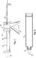
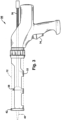
handheld caulk gun 10, as illustrated inFIG. 1 .Cartridges 12 shown inFIG. 2 having any number of different types of materials, including those listed above are inserted into acartridge support sleeve 14 located on the top side of thedispensing tool 10. Atrigger 16 on thegun 10 when actuated drives arack 18 having aplunger 20 that engages the material located in thecartridge 12 such that each actuation of the trigger, forces material to be dispensed from anozzle 22 located at anend 24 of the cartridge. - A more modern dispensing tool for applying various materials, including those materials listed above is a
power dispensing gun 30, having a battery, pneumatic, or other means for powering motor for portable use is illustrated inFIG. 3 . Thepower dispensing gun 30 is also capable of using thecartridges 12 filled with dispensing material by inserting thecartridges 12 into asupport sleeve 32 located on the top of thepower dispensing gun 30. A trigger 34 on thepower dispensing gun 30 is actuated, driving arack 36 having aplunger 38 that engages the material located in thecartridge 12 such that each actuation of the trigger forces material to be dispensed from anozzle 40 located at theend 42 of the gun. Further details of the operation and configuration of a power dispensing gun is explained inU.S. Patent Application Serial No. 11/918,689 entitled POWERED DISPENSING TOOL AND METHOD FOR CONTROLLING SAME that is assigned to the assignee of the present invention and is incorporated herein by reference in its entirety for all purposes. -
Cartridges 12 are not the only form of container for holding material used by the dispensingguns type container 50 shown inFIG. 4 . Thesausage pack 50 includes a first andsecond ends main body 56 having dispensing material therein. Thesausage pack 50 is positioned in ahousing tube 58 located on theguns cartridge support sleeves FIG. 5 and7 . Thesausage pack 50 once inserted into the guns has an opening 60 (shown in phantom is typically formed from removal of a containment ring or by piercing the sausage pack) toward thenozzle plunger trigger 16, 34 is engaged. - One example of a dispensing tool having interchanging support sleeves includes
U.S. Patent Application No. 11/973,242 filed on October 5, 2007 -
Sausage packs 50 are typically more economical because of their cheaper fabrication. As a result, thesausage packs 50 are typically used more frequently in high volume commercial and manufacturing operations overconventional cartridges 12 in material dispensing guns. -
EP 1 607 142 A1 (Sika Technology AG [CH]) 21 December 2005 , discloses a dispenser device (10) which has a drive (800) with piston (5) and guide rod (1). The piston (5) has two sides (5a, 5b) remote from each other with the first side acting on the material (20) to be processed which is contained in a bag (200) inserted in the cylinder (9) whilst the second side acts on the material to be processed which is contained in the cylinder of a cartridge inserted in the device. The piston has a threaded bore running right through so that the piston can be screwed onto the threaded bolt (12) with either the first or second side facing the guide rod. -
FR 2 646 790 A1 (Corso Dominique [FR]), 16 November 1990 -
DE 87 05 030 U1 (ARA-WERK Kramer GmbH + Co), 4 June 1987 , discloses an apparatus for discharging a bead or strand of pasty material from a deformable tubular container such as a tubular bag has a bag-loadable cylinder with a front face pointing in a discharge direction, the front face having a central opening aligned with a nozzle connection of the tubular bag. - A substantially piston-like pressure member is axially displaceable against the tubular bag in the cylinder. In order to avoid drooling and dribbling of material through the nozzle after interruption of the discharge process, and also to prevent jamming of the edges of the tubular bag, the pressure member has a pressure relief spring supported on the wall of the cylinder and cooperating therewith, the spring having spring tongues directed obliquely forward around the deformable bag.
- The present disclosure is directed to a material dispensing assembly for converting a portable cartridge dispensing tool to a bag-type dispensing tool. The assembly comprises a single piece piston for advancing material though a material housing. The single piece piston includes a substantially square-shaped receptacle. The assembly further comprises a square shaped drive rack for attaching to the piston at the substantially square-shaped receptacle at a connection end. The drive rack further comprises a plurality of teeth located thereon. The assembly further has a support with a substantially square profile for receiving and supporting the drive rack during operation such that the construct of the drive rack and piston are prevented from rotating during operation.
- One embodiment of the present disclosure concerns a single-piece piston for advancing material in a dispensing gun. The piston comprises first and second ends, the first end having a dome profile with an annular taper extending outwardly toward the second end. The piston further comprises a circular seal lip integral with and extending about the perimeter of the piston, the circular seal lip includes a plurality of substantially equal segments located therebetween. A noncircular attachment aperture is located in the piston for attaching the piston to a dispensing gun. The noncircular attachment aperture in the piston prevents loosening and rotation of the piston during operation.
- A further embodiment of the present disclosure includes a material dispensing gun assembly comprising a single piece piston for advancing material though a material housing. The single piece piston includes a substantially square-shaped receptacle for attaching the single piece piston to a dispensing gun and first and second ends. The first end includes an annular dome profile with first and second annular tapered surfaces extending outwardly toward the second end. The piston further comprises a circular seal lip integral and extending from the second annular tapered surface about the perimeter of the piston, the circular seal lip further comprises a plurality of substantially equal segments. The dispensing gun assembly also comprises a square shaped drive rack for attaching to the single-piece piston at the substantially square-shaped receptacle at a connection end and a plurality of teeth located thereon. The dispensing gun also includes a support having a substantially square profile for receiving and supporting the drive rack during operation such that the construct of the drive rack and piston are prevented from rotating during operation.
- A yet further embodiment of the present disclosure includes a method of dispensing material from a material dispensing gun comprising loading a sausage bag comprising dispensing material into a tube removably attached to a dispensing gun, the tube having an exit end from which the dispensing material is dispensed during operation. The method also comprises locating the sausage bag between the exit end and a single piece piston in the tube and engaging the sausage bag with an annular dome located at a front end of the single piece piston located in the tube. The method further comprises advancing the single piece piston against the sausage bag with a rack, fixedly attached to the single piece piston by a noncircular attachment aperture in the piston that prevents loosening and rotation of the piston during operation, such that material located in the sausage bag engaged by the annular dome is dispensed from the exit end of the tube and unadvanced material not engaged by the annular dome extends over first and second tapered annular surfaces of the dome. The method also includes engaging the unadvanced material in the sausage bag with a circular seal lip integral and extending from the second annular tapered surface about the perimeter of the piston, the circular seal lip comprises a plurality of substantially equal segments located about the perimeter of the circular seal lip and advancing the unadvanced material with the plurality of substantially equal segments of the single piece piston such that the unadvanced material located in the sausage bag engaged by the plurality of segments is dispensed from the exit end of the tube.
- An example of the present disclosure includes a material dispensing housing for use with bag-type dispensing material. The material dispensing housing comprises a transparent tube for supporting bag-type dispensing material, the tube is formed from high-temperature resistant polymeric material. The transparent tube allows for the visualization of the movement of dispensing material located within the housing during operation. The housing also comprises a base coating selected from one of a silicone coating and polysiloxane coating. The base coating provides superior service life and reduced friction of the bag holding the dispensing material and reduces the friction with a piston that engages the tube and the bag-type dispensing material during operation.
- The foregoing and other features and advantages of the present invention will become apparent to one skilled in the art to which the present invention relates upon consideration of the following description of the invention with reference to the accompanying drawings, wherein like reference numerals refer to like parts throughout the drawings and in which:
-
FIG. 1 is a side elevation view of a manual dispensing gun adapted for a cartridge-type material container; -
FIG. 2 is a side cross sectional elevation view of a cartridge-type material container for use in a manual or powered dispensing gun; -
FIG. 3 is a side elevation view of a power dispensing gun adapted for a cartridge-type material container; -
FIG. 4 is a side elevation view of a sausage pack material container for use in a manual or powered dispensing gun; -
FIG. 5 is a perspective view of a tube for housing a sausage pack material container ofFIG. 4 ; -
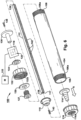
FIG. 6 is an exploded assembly view of a material dispensing assembly adapted for a power dispensing tool constructed in accordance with one embodiment of the present disclosure; -
FIG. 7 is a side view of a power dispensing gun adapted to support the material dispensing assembly ofFIG. 6 ; -
FIG. 8A is a rear isometric view of a single piece piston constructed in accordance with one embodiment of the present disclosure; -
FIG. 8B is a front isometric view of the single piece piston constructed in accordance with the example embodiment ofFIG. 8A ; -
FIG. 8C is a rear elevation view of the single piece piston constructed in accordance with the example embodiment ofFIG. 8A ; -
FIG. 8D is a side elevation view of the single piece piston constructed in accordance with the example embodiment ofFIG. 8A ; -
FIG. 8E is a front elevation view of the single piece piston constructed in accordance with the example embodiment ofFIG. 8A ; -
FIG. 8F is a cross-section elevation side view of the single piece piston constructed in accordance with the example embodiment ofFIG. 8A ; and -
FIG. 8G is a magnified view of a portion of the single piece piston cross-section identified in the example embodiment ofFIG. 8G . - The present disclosure relates to a
material dispensing assembly 100, and more particularly, a material dispensing assembly for easily converting portable cartridge dispensing tools to sausage or bag-type dispensing tools. One example embodiment of thematerial dispensing assembly 100 is illustrated inFIG. 6 . Theassembly 100 can be adapted to convert a power dispensing tool from the cartridge-type dispenser illustrated inFIG. 3 to that of a sausage type dispenser as illustrated in the example embodiment of thepower dispensing tool 102 inFIG. 7 that can be powered by battery, pneumatic means, and the like. - The
power dispensing assembly 100 ofFIG. 6 comprises asausage holding tube 104 having first and second ends 106, 108, respectively. Asausage pack 50 of various lengths is installed through thefirst end 106 and material within the sausage pack is forced out by apiston 110 that is located behind the sausage pack in thesecond end 108 during operation. The material that is dispensed from thesausage pack 50 could include caulk, adhesives, silicone, urethanes, and the like without departing from the spirit and scope of the claimed invention. Thepiston 110 is advanced by asquare piston rack 112, which forces the piston against thesausage pack 50, forcing material to dispense from thefirst end 106 through anozzle 114 that is retained to thetube 104 by acap 116 via a threadedconnection 117. - The amount and speed of the material dispensed from the
sausage pack 50 by thepiston 110 could be a function of the speed of the motor (internal to the gun), or the extent of travel by the piston in thetube 104. For example, thepiston 110 could "bottom-out" against anempty sausage pack 50 that is compressed against thecap 116 andnozzle 114. Therack 112 moveably passes through components internal to thegun 102, including a pinion gear 118 (that engages and drives the rack in both forward and reverse directions) coupled to agear set 120 driven in both a forward and reverse direction by amotor 122. The positioning of the gear set 120 andpinion gear 118 in combination withsupports 124 internal to thegun 102, fix the orientation of therack 112 through its path of travel when advancing and reversing thepiston 110 in thetube 104. Thesupports 124 comprise square shaped bushings, guides, or fixtures that maintain the orientation of therack 112 to prevent rotation of the rack orpiston 110 during operation. - The
rack 112 includes first 126 and second 128 ends. Thefirst end 126 passes through abarrel screw 127,spacer 130,end cap 132, andwasher 134. Thebarrel screw 127 couples the dispensingassembly 100 through thespacer 130 andend cap 132 to a mating threadedconnection 133 located in a housing porting 135 of thegun 102 for engagement with the barrel screw. Attached to thefirst end 126 of therack 112 is arack handle 136 for assisting in the reloading and unloading of the sausage packs 50 from thetube 104. The rack handle 136 is secured to a threaded aperture located in thefirst end 126 of rack by ascrew 138. - The first and second ends 106, and 108, respectively have respective threaded sections 106A and 108A. The first threaded section 106A co-acts with internal threads 116A associated with
cap 116 and secures the cap to thefirst end 106 of thetube 104, locking thenozzle 114 between the tube and cap at the first end. The second threaded section 108A co-acts with internal threads 132A associated withend cap 132. Once theend cap 132 is secured to thehousing 135 of the dispensinggun 102, as described above, the second threaded second 108A is screwed into the end cap, thereby supporting thetube 104 to the housing. -
Plungers 20 used in conventional dispensing guns (seeFIG. 1 ), are commonly threaded on the end of adrive rack 18. Tightening theplunger 20 to the rack and applying a lock-nut is a typical means of securing the plunger. As somecartridges 12 and their corresponding support sleeves are designed to be rotated, the tendency to have theplunger 20 "unscrew" from the drive rack is appreciable, especially during operations when the user is attempting to turn thecartridge 12 while there is axial pressure being applied to the drive rack. - Such problems are resolved by one embodiment of the present invention. In particular, the
rack 112 comprises a square configuration to be received and attached to a corresponding asquare receptacle 140 in thepiston 110, as illustrated inFIGS. 8A, 8C, and 8F . Therack 112 engages the receptacle until it is in contact with aninternal face 141 in thepiston 110 and is secured to the piston by afastener 143 that passes through anopening 165 into a counter-bore 167, for seating the fastener during attachment. Such design and the corresponding square supports 124 internal to thegun 102 prevent rotation of therack 112 and preclude any loosening of thepiston 110. - The
rack 112 construction in the illustrated embodiment ofFIG. 6 provides yet another advantage from the present disclosure. Thesquare piston 110, correspondingsquare receptacle 140, and rack 112 allow the rack to be reversed such that thefirst end 126 can be flipped with thesecond end 128. Thisreversible rack 112 feature is advantageous when the rack becomes worn by thepinion gear 118 along an advanced direction (see arrow A inFIG. 6 ). At such time that therack 112 shows signs of wear, the mirror image construction and corresponding attachments allow the rack to be flipped 180 degrees between the first and second ends 126, 128 while remaining in the same orientation as shown inFIG. 6 . Thepinion 118 now drives unworn teeth 142 in the advanced direction "A". Thefasteners rack 112 at first and second ends 126, 128 are the same, allowing thepiston 110 and rack handle 136 to be reversed, extending the life of the rack as discussed above. - The
piston 110 provides several advantages illustrated in the exemplary embodiment ofFIGS. 6 and8 . Whileconventional plungers 20 are typically configured from multiple pieces, thepiston 110 is a single uniform piece made from a single molding operation. This eliminates both material and assembly costs experienced in conventional plunger designs. While thepiston 110 can be made from any number of suitable polymeric materials, the construct of the piston in the example embodiment is formed from Nylon 66 material. The polymeric material of thepiston 110 advantageously weighs less than one ounce, while compared to conventional plungers that weigh much more and up to eight ounces. The reduction in weight in the exemplary embodiment of thesingle piece piston 110 reduces stress, strain, and other ergonomic issues typically experienced in wrists and arms of operators using conventional dispensing guns. - The
piston 110 comprisesfront 144 and back 146 ends as shown inFIGS. 8B and 8D , anannular dome 148, andcircular lip portion 150, as shown inFIG. 8C . The construct of theannular dome 148 at thefront 144 of thepiston 110 is designed to extrude the maximum amount of material from thetube 104 andsausage packet 50 therein. In particular, thedome 148 comprises a first taperedannular surface 151, raising the unadvanced material in thesausage packet 50 up over the tapered annular face to a plurality of segmented sections 152 integrated into the dome and extending from thesingle piece piston 110. In the illustrated embodiment, twelve (12) segmented sections represented by 152A-152L (seeFIG. 8E ) in thecircular lip portion 150 capture and advance forward the remaining material in thesausage packet 50 as thepiston 110 advances through thetube 104. While twelve segmented sections 152 are shown in the illustrated embodiment ofFIGS. 8 , more or less segmented sections could be used without departing from the spirit and scope of the claimed invention. - The independent flexibility achieved by the
segmented sections 152A-152L provide a heightened ability to facilitate a solid lip seal to atube 104 orcartridge 12 internal wall under varying roundness tolerances especially experienced in cartridge tubes. Further thespecific piston 110 diameter, piston lip geometry, including thickness, taper, and edge angles provide dispensing free of "bag wrap" failures, while enabling a low "pull back" force in sausage-type applications. In addition, thepiston 110 design provides a low drag force in the forward direction (see arrow A inFIG. 6 ), enabling greater dispensing forces to be achieved. In the illustrated embodiment ofFIGS. 8A-8G , the lip thickness represented by dimension "A" inFIG. 8G is approximately 8.64mm (0.34 inches), having afront taper 162 of approximately 6 degrees represented by dimension "B", and edge angle off arear edge 160 of each segmented sections 152 of approximately 15 degrees represented by dimension "C", and a back angle off a second taperedannular surface 163 on thedome 151 of approximately 92 degrees represented by dimension "D", as illustrated inFIGS. 8F and 8G . - The twelve
segmented sections 152A-152L are capable under the current embodiment ofFIG. 8 of independently undulating to maintain substantially constant regulated pressure to thesausage pack 50, preventing bag wrap failures where the bag of thesausage pack 50 would pinch between the plunger and tube in conventional plunger designs. In the exemplary embodiment ofFIGS. 8A-8G , avent spacing 154 is provided between the 12segmented sections 152A-152L of approximately 0.762mm (0.030 inches) represented by dimension "X" inFIG. 8E . The overall length of the piston is approximately 25.4mm (1 inch) represented by dimension "E" inFIG. 8D and the overall diameter of thepiston 110 in the illustrated embodiment ofFIG. 8 is approximately 50.8mm (2.0 inches) as illustrated inFIG. 8E by dimension "F", and the segmented sections extend from thedome 151 outward at approximately 17.53mm (0.69 inch) diameter radius from the center "O" of the piston. It should be appreciated however, that proportionally larger and smaller dimensions would be required for larger and smaller diameter tubes and are intended to be covered by the spirit and scope of the claimed invention. The vent spacings 154 in addition to providing independent pressure to the inner diameter of thetube 104 and/orsausage pack 50, allow air to escape from the tube when the sausage pack is being inserted or removed. This allows for easier replacement and removal of sausage packs 50 during operation by the user. Thepiston 110 also comprises a number of voids on theback end 146. Thevoids 155 improve the overall structural strength and facilitate a reduction in the weight of thepiston 110. - The
tube 104 in one exemplary embodiment is transparent so that the material dispensed from thesausage pack 50 can be observed and visually measured by the user. - In addition, the
transparent tube 104 allows the user to visually inspect the tube while performing a cleaning operation. - In another example embodiment, the
tube 104 is transparent (i.e. clear and chemical resistant) and made from an a high temperature annealed polycarbonate or polyamide basedmaterial 82 and lined with a basedcoating 84, allowing superior service life in a demanding environment of repeated stress, thermal, and chemical attack. Examples of suitable base coatings include silicone or polysiloxane. Such construction also reduces friction with thepiston 110 andsausage bag 50 and reduces the force necessary for dispensing the material from the dispensinggun 102. Thebase coatings 84 can be applied to thetube 104 by direct application, such as spraying or wiping the internal portions of the tube, through a heat treatment application process, or by extruding or impregnating thebase material 82 with the base coating material during the forming of the base material. - What have been described above are examples of the present invention. It is, of course, not possible to describe every conceivable combination of components or methodologies for purposes of describing the present invention, but one of ordinary skill in the art will recognize that many further combinations and permutations of the present invention are possible. For example, while the material dispensing assembly was illustrated being adapted to a power dispensing gun, it could equally be adapted to a manual dispensing gun without departing from the spirit or scope of the claimed invention. Accordingly, the present invention is intended to embrace all such alterations, modifications, and variations that fall within the scope of the appended claims.
Claims (13)
- A single-piece piston (110) for advancing material in a dispensing gun comprising:first and second ends (144, 146), the first end having a dome profile with an annular taper extending outwardly toward said second end;a circular seal lip (150) integral and extending from said annular taper (165) about the perimeter of the piston (110), the circular seal lip (150) comprising a plurality of substantially equal segments (152) located therebetween; anda noncircular attachment aperture (140) for attaching said piston (110) to a rack of a dispensing gun wherein said piston is molded from a polymeric material.
- The single-piece piston of claim 1 further comprises a plurality of support voids (155) comprised within a face of the second end (146).
- The single-piece piston of claim 2 wherein said piston is molded from a uniform polymeric material.
- The single-piece piston of any of claims 1 to 3 wherein the annular taper comprises first and second taper portions, the first taper portion originating at said first end and a second taper portion originating at an end of the first taper portion and extending to said circular lip seal (150) at said second end, the first taper having a first incline angle that is greater than a second incline angle of said second taper.
- The single-piece piston of any of claims 1 to 4 wherein said plurality of segments forming said circular seal lip are formed by a vent spacing between each of said segments, said vent spacing providing independent movement between each of said segments (152A - 152L) during operation.
- A material dispensing gun assembly comprising: a single piece piston according to any of claims 1 to 5.
- A method of dispensing material from a material dispensing gun comprising;loading a sausage bag comprising dispensing material into a tube removably attached to a dispensing gun, the tube having an exit end from which the dispensing material is dispensed during operation;locating said sausage bag between the exit end and a single piece piston in said tube;engaging the sausage bag with an annular dome located at a front end of the single piece piston located in said tube;advancing said single piece piston against said sausage bag with a rack, fixedly attached to said single piece piston by a noncircular attachment aperture in the piston that prevents loosening and rotation of the piston during operation, such that material located in said sausage bag engaged by said annular dome is dispensed from the exit end of said tube and unadvanced material not engaged by said annular dome extends over first and second tapered annular surfaces of said dome;engaging the unadvanced material in said sausage bag with a circular seal lip integral and extending from said second annular tapered surface about the perimeter of the piston, the circular seal lip comprising a plurality of substantially equal segments located about the perimeter of the circular seal lip the piston molded as a single piece from a polymeric material; and advancing the unadvanced material with the plurality of substantially equal segments of said single piece piston such that the unadvanced material located in the sausage bag engaged by the plurality of segments is dispensed from the exit end of said tube.
- The material dispensing gun assembly of claim 6 wherein said single piece piston is internally located in the dispensing gun.
- The material dispensing gun assembly of claim 8 wherein said dispensing gun (100) is one of a manually operated dispensing assembly or power operated dispensing assembly.
- The material dispensing gun assembly of claim 6 or claim 8 or claim 9 wherein the single piece piston is attached to a substantially square-shaped receptacle (140).
- The material dispensing gun assembly of any of claims 6, 8, 9 or 10 wherein said piston (110) is attached to a square shaped drive rack (112) at the substantially square-shaped receptacle (140) at a connection end (128) and a plurality of teeth located thereon (142).
- The material dispensing gun assembly of claim 10 wherein said piston (110) is attached to a support (127) having a substantially square profile for receiving and supporting said drive rack (112) during operation such that the construct of said drive rack and piston (110) are prevented from rotating during operation of said dispensing gun (100).
- The material dispensing gun assembly of claim 11 or claim 12 wherein said drive rack (112) is reversibly interchangeable.
Applications Claiming Priority (3)
| Application Number | Priority Date | Filing Date | Title |
|---|---|---|---|
| US5040608P | 2008-05-05 | 2008-05-05 | |
| US12/434,024 US8424727B2 (en) | 2008-05-05 | 2009-05-01 | Material dispensing assembly |
| PCT/US2009/042679 WO2009137390A1 (en) | 2008-05-05 | 2009-05-04 | Material dispensing assembly |
Publications (3)
| Publication Number | Publication Date |
|---|---|
| EP2303763A1 EP2303763A1 (en) | 2011-04-06 |
| EP2303763A4 EP2303763A4 (en) | 2018-02-28 |
| EP2303763B1 true EP2303763B1 (en) | 2024-07-03 |
Family
ID=41256439
Family Applications (1)
| Application Number | Title | Priority Date | Filing Date |
|---|---|---|---|
| EP09743377.5A Active EP2303763B1 (en) | 2008-05-05 | 2009-05-04 | Material dispensing assembly |
Country Status (5)
| Country | Link |
|---|---|
| US (3) | US8424727B2 (en) |
| EP (1) | EP2303763B1 (en) |
| CN (2) | CN102066237B (en) |
| ES (1) | ES2989107T3 (en) |
| WO (1) | WO2009137390A1 (en) |
Families Citing this family (49)
| Publication number | Priority date | Publication date | Assignee | Title |
|---|---|---|---|---|
| US9517488B2 (en) * | 2004-12-30 | 2016-12-13 | Plas-Pak Industries, Inc. | Component delivery system utilizing film bags |
| US20100108709A1 (en) | 2004-12-30 | 2010-05-06 | Plas-Pak Industries | Cartridge delivery system utilizing film bags |
| US8424727B2 (en) | 2008-05-05 | 2013-04-23 | Meritool Llc | Material dispensing assembly |
| WO2012068092A2 (en) | 2010-11-15 | 2012-05-24 | Milwaukee Electric Tool Corporation | Powered dispensing tool |
| WO2012067801A1 (en) | 2010-11-15 | 2012-05-24 | Milwaukee Electric Tool Corporation | Powered dispensing tool |
| US8857672B2 (en) | 2011-06-20 | 2014-10-14 | Milwaukee Electric Tool Corporation | Carriage assembly for dispensing tool |
| US9039557B2 (en) | 2011-09-02 | 2015-05-26 | Milwaukee Electric Tool Corporation | Powered dispensing tool |
| US20130153600A1 (en) * | 2011-10-06 | 2013-06-20 | Clear Lam Packaging, Inc. | Dispenser system for flexible bags |
| CH705569A1 (en) * | 2011-11-01 | 2013-05-15 | Medmix Systems Ag | Discharge apparatus for semi-solid materials. |
| US9694944B2 (en) * | 2012-03-06 | 2017-07-04 | Prince Castle LLC | Dispenser for viscous food products |
| USD748243S1 (en) * | 2013-08-06 | 2016-01-26 | Michael Perthu | Auto-injector |
| USD756507S1 (en) * | 2013-09-04 | 2016-05-17 | Michael Perthu | Auto-injector |
| US9538872B2 (en) | 2014-03-07 | 2017-01-10 | Prince Castle LLC | Pressurized viscous condiment dispenser |
| CA2956438C (en) | 2014-07-28 | 2023-03-21 | Cryovac, Inc. | Dispensing system, packaging system, package, closure system, dispensing gun system, method of making a package, and method of dispensing a product |
| US10118192B2 (en) * | 2014-08-13 | 2018-11-06 | Rodney Hoover | Caulking cannon |
| JP5651803B1 (en) | 2014-08-25 | 2015-01-14 | 加賀ワークス株式会社 | Plunger for pneumatic dispenser |
| CN104153161A (en) * | 2014-08-28 | 2014-11-19 | 济南大学 | Coating device for liquid washing |
| US9723845B2 (en) * | 2014-12-12 | 2017-08-08 | Helen Of Troy Limited | Dispensing gun |
| TWI576167B (en) * | 2015-04-02 | 2017-04-01 | 翔宣富企業有限公司 | Push member and caulking gun having the same |
| FR3042390B1 (en) * | 2015-10-15 | 2017-11-24 | Albea Le Treport | BOTTLE AND METHOD FOR MANUFACTURING A BOTTLE TUBE FOR BOTTLE |
| WO2017068389A1 (en) * | 2015-10-18 | 2017-04-27 | Ng Chiu Ho | A dispensing device for conveniently dispensing material |
| JP5993077B1 (en) | 2015-10-19 | 2016-09-14 | 加賀ワークス株式会社 | Viscous material dispenser cartridge |
| US9937519B2 (en) * | 2016-05-13 | 2018-04-10 | Franke Technology and Trademark, Ltd. | Kit for adapting dispensers to dispense materials from flexible-walled containers |
| DE202016103241U1 (en) * | 2016-06-20 | 2017-09-21 | Marco Roth | Sheath for receiving and adapting a cartridge to an ejection device and ejection device |
| CN106043964B (en) * | 2016-08-13 | 2018-07-10 | 台州市压缩机制造有限公司 | A kind of hand-held pneumatic extrusion device towards hard tube shell packaging soft paste |
| RU2019111778A (en) * | 2016-10-19 | 2020-11-20 | Криовак, Ллк | DOSING SYSTEM |
| US10766053B2 (en) * | 2017-01-04 | 2020-09-08 | Red Devil, Inc. | Material dispensing system and method |
| US10640280B2 (en) | 2017-04-05 | 2020-05-05 | Meritool Llc | Trigger assembly and method of operation |
| CN108792204A (en) * | 2017-04-27 | 2018-11-13 | 南京光谷数据处理有限公司 | Cardboard cylinder packing container for oxidation drying type ink |
| CN108168639B (en) * | 2017-12-11 | 2019-09-10 | 中国航空工业集团公司北京长城计量测试技术研究所 | A kind of passive piston volume tube of overturning valve plug type |
| US10968031B2 (en) | 2017-12-27 | 2021-04-06 | Sulzer Mixpac Ag | Piston for a collapsible cartridge |
| EP4613387A3 (en) | 2018-09-19 | 2025-11-19 | PRC-Desoto International, Inc. | Expandable plunger head assemblies for sealant dispensing guns |
| EP3632575A1 (en) * | 2018-10-02 | 2020-04-08 | Sulzer Mixpac AG | Reusable cartridge piston |
| EP3714994A1 (en) * | 2019-03-26 | 2020-09-30 | Sulzer Mixpac AG | Piston, cartridge, dispenser |
| US11654453B1 (en) * | 2019-07-09 | 2023-05-23 | Jacob Burns | Roof coating applicator |
| WO2021242633A1 (en) * | 2020-05-23 | 2021-12-02 | Inspire Medical Systems, Inc. | Single or multiple nerve stimulation to treat sleep disordered breathing |
| CN111992452B (en) * | 2020-08-21 | 2021-06-29 | 深圳市威利佳汽车配件有限公司 | A spacing auxiliary device that glues for auto-parts processing |
| WO2022081417A1 (en) * | 2020-10-13 | 2022-04-21 | Prc-Desoto International, Inc. | Plungers for sealant dispensing cartridges with collapsible sealant packaging |
| EP4052798A1 (en) * | 2021-03-01 | 2022-09-07 | medmix Switzerland AG | Dispenser, cartridge assembly, support sleeve and method of operating a dispenser |
| WO2023067556A1 (en) * | 2021-10-21 | 2023-04-27 | Oak Properties, Llc | Reversible caulk dispenser |
| US12227351B1 (en) * | 2021-11-08 | 2025-02-18 | Diamond Age 3D, Inc. | Reusable cartridge based system for precision placement of construction materials |
| US12649167B2 (en) * | 2021-11-19 | 2026-06-09 | Red Devil, Inc. | Plunger system, device and method |
| US12054334B2 (en) | 2021-11-19 | 2024-08-06 | Red Devil, Inc. | Sausage package dispensing system, device and method |
| KR200496329Y1 (en) * | 2022-05-30 | 2023-01-03 | 허영호 | Silicone Vinyl Tube Assembly Structure |
| WO2024220315A2 (en) * | 2023-04-21 | 2024-10-24 | Red Devil Inc. | Plunger system, device and method |
| US12612976B2 (en) | 2023-06-26 | 2026-04-28 | Franke Kindred Canada Limited | Valve assembly for dispensing foodstuff and dispenser apparatus and lid comprising the same |
| KR200500595Y1 (en) * | 2024-04-04 | 2026-07-29 | 서강덕 | oil container |
| US12447497B2 (en) | 2024-10-30 | 2025-10-21 | Dripless, Inc. | Caulking gun load sensitive variable ratio drive device |
| US12311403B1 (en) * | 2024-11-15 | 2025-05-27 | TEMCo Industrial, LLC | Drill powered caulking gun |
Family Cites Families (35)
| Publication number | Priority date | Publication date | Assignee | Title |
|---|---|---|---|---|
| US1235550A (en) * | 1916-07-07 | 1917-08-07 | Joseph M Levine | Fire-extinguisher. |
| US2138045A (en) * | 1936-07-06 | 1938-11-29 | Pecora Paint Company | Ratchet mechanism |
| US2371332A (en) * | 1942-09-25 | 1945-03-13 | James J Jacobson | Dispensing container |
| US3215320A (en) * | 1963-11-18 | 1965-11-02 | Heisler Harold | Container and dispenser for dispensing predetermined, set, measured amounts of material |
| US3527389A (en) * | 1968-10-25 | 1970-09-08 | Dow Chemical Co | Caulking cartridge with silicone fluid seal |
| US3997085A (en) | 1976-01-15 | 1976-12-14 | Berkley James Lindquist | Caulking gun |
| US4134523A (en) * | 1977-05-09 | 1979-01-16 | Southern Can Company | Vented piston for barrier pressure containers |
| US4741462A (en) * | 1981-10-29 | 1988-05-03 | Albion Engineering Company | Adjustable piston packing expander for caulking guns |
| USD285895S (en) | 1983-05-25 | 1986-09-30 | P.C. Cox (Newbury) Limited | Mastic gun |
| DE8705030U1 (en) * | 1986-07-30 | 1987-06-04 | Ara-Werk Krämer GmbH + Co, 7441 Unterensingen | Device for strand-shaped discharge of pasty masses |
| US4776458A (en) | 1986-08-11 | 1988-10-11 | Sashco, Inc. | Materials container |
| GB2197425B (en) | 1986-11-12 | 1990-02-28 | Metal Box Plc | Pistons for pressure-dispensing containers |
| US4744494A (en) * | 1986-12-01 | 1988-05-17 | Calumet Manufacturing Co. | Ram gun |
| FR2646790B1 (en) * | 1989-05-09 | 1991-10-04 | Corso Dominique | IMPROVEMENTS ON PISTOLS FOR THE EXTRUSION OF PASTY PRODUCTS |
| US5027984A (en) | 1989-09-12 | 1991-07-02 | Vermont American Corporation | Caulking gun attachment for use with a high RPM power driver and capable of being driven either directly at full speed or indirectly at a lower speed via a gear reducer |
| DE4226956A1 (en) * | 1992-08-14 | 1994-02-17 | Friedhelm Schneider | Hydraulic dispensing pistol for material in hose-type bag - has disc on piston extension expanding against housing |
| US5301835A (en) * | 1992-09-17 | 1994-04-12 | Dow Corning Corporation | Adapter for dispensing material from a sausage type package |
| US5390831A (en) | 1993-12-06 | 1995-02-21 | Albion Engineering Company | Dispensing devices for high viscosity compositions |
| DE9400524U1 (en) * | 1994-01-13 | 1995-05-18 | Thera Ges Fuer Patente | Device for emptying a tubular bag |
| DE29608299U1 (en) * | 1996-05-08 | 1996-08-01 | Su, Wei-Chieh, Hsiu-Shui Hsiang, Changhua | Press gun for cartridges |
| EP0867403A1 (en) * | 1997-03-24 | 1998-09-30 | Sicpa Holding S.A. | Scraping element, piston and arrangement for emptying a bag-like envelope containing a pasty liquid |
| DE19753766A1 (en) * | 1997-12-04 | 1999-06-17 | Schott Glas | Elongated hollow plastic body and process for its production |
| DE10036832C1 (en) * | 2000-07-28 | 2001-12-13 | Schott Glas | Applying heat fixed lubricant layer onto inner wall of cylindrical medical containers comprises applying lubricant, homogenizing to layer and selectively heat-fixing lubricant layer using IR radiation |
| AU2003209614A1 (en) | 2002-01-29 | 2003-09-02 | Zeev Brandeis | Caulking gun |
| US6712245B2 (en) | 2002-07-15 | 2004-03-30 | Arther Barrett | Venting plunger for caulk cartridges |
| US6701828B1 (en) * | 2002-12-10 | 2004-03-09 | Wilton Industries, Inc. | Automatic cookie press |
| CN1849250A (en) * | 2003-07-31 | 2006-10-18 | 丹尼·拉姆里尔 | Improved caulking gun |
| WO2005050068A1 (en) | 2003-11-13 | 2005-06-02 | Meritool Llc | Viscous material dispenser piston |
| US20090065527A1 (en) * | 2004-06-14 | 2009-03-12 | Manuel Buck | Device and method for the release of material for processing |
| EP1607142A1 (en) | 2004-06-14 | 2005-12-21 | Sika Technology AG | Device for dispensing a material |
| US20060091158A1 (en) * | 2004-10-29 | 2006-05-04 | Sonoco Development, Inc. | High-barrier plastic caulk cartridge and method of making same |
| US8011538B2 (en) | 2007-02-21 | 2011-09-06 | Meritool, Llc | Dispensing tool |
| CN201147749Y (en) * | 2007-10-31 | 2008-11-12 | 东莞长鸿五金制品有限公司 | glue gun |
| US8424727B2 (en) | 2008-05-05 | 2013-04-23 | Meritool Llc | Material dispensing assembly |
| CN103998149B (en) * | 2011-10-17 | 2017-03-29 | 苏舍米克斯帕克有限公司 | Cylinder and multicomponent cartridge |
-
2009
- 2009-05-01 US US12/434,024 patent/US8424727B2/en active Active
- 2009-05-04 EP EP09743377.5A patent/EP2303763B1/en active Active
- 2009-05-04 CN CN200980123059.7A patent/CN102066237B/en not_active Expired - Fee Related
- 2009-05-04 CN CN201410222190.1A patent/CN104097840B/en not_active Expired - Fee Related
- 2009-05-04 WO PCT/US2009/042679 patent/WO2009137390A1/en not_active Ceased
- 2009-05-04 ES ES09743377T patent/ES2989107T3/en active Active
-
2013
- 2013-04-05 US US13/857,235 patent/US8950627B2/en active Active
-
2014
- 2014-11-21 US US14/550,450 patent/US9694384B2/en active Active
Also Published As
| Publication number | Publication date |
|---|---|
| US20090272767A1 (en) | 2009-11-05 |
| US9694384B2 (en) | 2017-07-04 |
| WO2009137390A1 (en) | 2009-11-12 |
| EP2303763A1 (en) | 2011-04-06 |
| CN102066237A (en) | 2011-05-18 |
| CN104097840A (en) | 2014-10-15 |
| CN104097840B (en) | 2017-05-31 |
| ES2989107T3 (en) | 2024-11-25 |
| EP2303763A4 (en) | 2018-02-28 |
| US20130306671A1 (en) | 2013-11-21 |
| CN102066237B (en) | 2014-07-02 |
| US8424727B2 (en) | 2013-04-23 |
| US8950627B2 (en) | 2015-02-10 |
| US20150076171A1 (en) | 2015-03-19 |
Similar Documents
| Publication | Publication Date | Title |
|---|---|---|
| US8424727B2 (en) | Material dispensing assembly | |
| US5027984A (en) | Caulking gun attachment for use with a high RPM power driver and capable of being driven either directly at full speed or indirectly at a lower speed via a gear reducer | |
| JP5444320B2 (en) | dispenser | |
| US8393501B2 (en) | Dispensing tool | |
| US7690530B2 (en) | Dispenser for viscous material | |
| US20090065527A1 (en) | Device and method for the release of material for processing | |
| US20040211789A1 (en) | Grouting gun apparatus and method | |
| US6382466B1 (en) | Device for dispensing flowable materials from a plurality of cartridge assemblies | |
| JP2018126734A (en) | Motorized cartridge type fluid dispensing apparatus and system | |
| US6041976A (en) | Adhesive dispensing tool for use with a rotary power tool | |
| EP1141501B1 (en) | A cartridge dispensing gun | |
| MXPA01006729A (en) | Fluid dispensing apparatus. | |
| US5076473A (en) | Power caulking gun | |
| US20100237104A1 (en) | Cove Base Nozzle for Dispensing Applications | |
| CA2570384A1 (en) | Device and method for the release of material for processing | |
| EP3512658B1 (en) | Device adapted to dosing pasty substances | |
| CN221602442U (en) | Joint filling tool | |
| CN114929401A (en) | Apparatus and method for improved dispensing control during viscous material placement | |
| US20020145015A1 (en) | Caulking gun carriage | |
| GB2060780A (en) | Gun for applying mastic material | |
| US10272465B1 (en) | Dispensing tool | |
| EP0998983A2 (en) | Apparatus for pressurising and dispensing a pasty material | |
| CN117619682A (en) | a caulking tool | |
| WO2019207547A2 (en) | Caulking gun extension set |
Legal Events
| Date | Code | Title | Description |
|---|---|---|---|
| PUAI | Public reference made under article 153(3) epc to a published international application that has entered the european phase |
Free format text: ORIGINAL CODE: 0009012 |
|
| 17P | Request for examination filed |
Effective date: 20101202 |
|
| AK | Designated contracting states |
Kind code of ref document: A1 Designated state(s): AT BE BG CH CY CZ DE DK EE ES FI FR GB GR HR HU IE IS IT LI LT LU LV MC MK MT NL NO PL PT RO SE SI SK TR |
|
| AX | Request for extension of the european patent |
Extension state: AL BA RS |
|
| DAX | Request for extension of the european patent (deleted) | ||
| RA4 | Supplementary search report drawn up and despatched (corrected) |
Effective date: 20180125 |
|
| RIC1 | Information provided on ipc code assigned before grant |
Ipc: G01F 11/02 20060101AFI20180119BHEP |
|
| STAA | Information on the status of an ep patent application or granted ep patent |
Free format text: STATUS: EXAMINATION IS IN PROGRESS |
|
| 17Q | First examination report despatched |
Effective date: 20210607 |
|
| GRAP | Despatch of communication of intention to grant a patent |
Free format text: ORIGINAL CODE: EPIDOSNIGR1 |
|
| STAA | Information on the status of an ep patent application or granted ep patent |
Free format text: STATUS: GRANT OF PATENT IS INTENDED |
|
| INTG | Intention to grant announced |
Effective date: 20240220 |
|
| GRAS | Grant fee paid |
Free format text: ORIGINAL CODE: EPIDOSNIGR3 |
|
| GRAA | (expected) grant |
Free format text: ORIGINAL CODE: 0009210 |
|
| STAA | Information on the status of an ep patent application or granted ep patent |
Free format text: STATUS: THE PATENT HAS BEEN GRANTED |
|
| P01 | Opt-out of the competence of the unified patent court (upc) registered |
Effective date: 20240521 |
|
| AK | Designated contracting states |
Kind code of ref document: B1 Designated state(s): AT BE BG CH CY CZ DE DK EE ES FI FR GB GR HR HU IE IS IT LI LT LU LV MC MK MT NL NO PL PT RO SE SI SK TR |
|
| REG | Reference to a national code |
Ref country code: CH Ref legal event code: EP |
|
| REG | Reference to a national code |
Ref country code: DE Ref legal event code: R096 Ref document number: 602009065291 Country of ref document: DE |
|
| REG | Reference to a national code |
Ref country code: LT Ref legal event code: MG9D |
|
| REG | Reference to a national code |
Ref country code: NL Ref legal event code: MP Effective date: 20240703 |
|
| REG | Reference to a national code |
Ref country code: ES Ref legal event code: FG2A Ref document number: 2989107 Country of ref document: ES Kind code of ref document: T3 Effective date: 20241125 |
|
| PG25 | Lapsed in a contracting state [announced via postgrant information from national office to epo] |
Ref country code: PT Free format text: LAPSE BECAUSE OF FAILURE TO SUBMIT A TRANSLATION OF THE DESCRIPTION OR TO PAY THE FEE WITHIN THE PRESCRIBED TIME-LIMIT Effective date: 20241104 |
|
| REG | Reference to a national code |
Ref country code: AT Ref legal event code: MK05 Ref document number: 1700247 Country of ref document: AT Kind code of ref document: T Effective date: 20240703 |
|
| PG25 | Lapsed in a contracting state [announced via postgrant information from national office to epo] |
Ref country code: NL Free format text: LAPSE BECAUSE OF FAILURE TO SUBMIT A TRANSLATION OF THE DESCRIPTION OR TO PAY THE FEE WITHIN THE PRESCRIBED TIME-LIMIT Effective date: 20240703 |
|
| PG25 | Lapsed in a contracting state [announced via postgrant information from national office to epo] |
Ref country code: PT Free format text: LAPSE BECAUSE OF FAILURE TO SUBMIT A TRANSLATION OF THE DESCRIPTION OR TO PAY THE FEE WITHIN THE PRESCRIBED TIME-LIMIT Effective date: 20241104 Ref country code: NL Free format text: LAPSE BECAUSE OF FAILURE TO SUBMIT A TRANSLATION OF THE DESCRIPTION OR TO PAY THE FEE WITHIN THE PRESCRIBED TIME-LIMIT Effective date: 20240703 |
|
| PG25 | Lapsed in a contracting state [announced via postgrant information from national office to epo] |
Ref country code: NO Free format text: LAPSE BECAUSE OF FAILURE TO SUBMIT A TRANSLATION OF THE DESCRIPTION OR TO PAY THE FEE WITHIN THE PRESCRIBED TIME-LIMIT Effective date: 20241003 |
|
| PG25 | Lapsed in a contracting state [announced via postgrant information from national office to epo] |
Ref country code: GR Free format text: LAPSE BECAUSE OF FAILURE TO SUBMIT A TRANSLATION OF THE DESCRIPTION OR TO PAY THE FEE WITHIN THE PRESCRIBED TIME-LIMIT Effective date: 20241004 Ref country code: FI Free format text: LAPSE BECAUSE OF FAILURE TO SUBMIT A TRANSLATION OF THE DESCRIPTION OR TO PAY THE FEE WITHIN THE PRESCRIBED TIME-LIMIT Effective date: 20240703 Ref country code: PL Free format text: LAPSE BECAUSE OF FAILURE TO SUBMIT A TRANSLATION OF THE DESCRIPTION OR TO PAY THE FEE WITHIN THE PRESCRIBED TIME-LIMIT Effective date: 20240703 |
|
| PG25 | Lapsed in a contracting state [announced via postgrant information from national office to epo] |
Ref country code: BG Free format text: LAPSE BECAUSE OF FAILURE TO SUBMIT A TRANSLATION OF THE DESCRIPTION OR TO PAY THE FEE WITHIN THE PRESCRIBED TIME-LIMIT Effective date: 20240703 |
|
| PG25 | Lapsed in a contracting state [announced via postgrant information from national office to epo] |
Ref country code: LV Free format text: LAPSE BECAUSE OF FAILURE TO SUBMIT A TRANSLATION OF THE DESCRIPTION OR TO PAY THE FEE WITHIN THE PRESCRIBED TIME-LIMIT Effective date: 20240703 |
|
| PG25 | Lapsed in a contracting state [announced via postgrant information from national office to epo] |
Ref country code: IS Free format text: LAPSE BECAUSE OF FAILURE TO SUBMIT A TRANSLATION OF THE DESCRIPTION OR TO PAY THE FEE WITHIN THE PRESCRIBED TIME-LIMIT Effective date: 20241103 Ref country code: AT Free format text: LAPSE BECAUSE OF FAILURE TO SUBMIT A TRANSLATION OF THE DESCRIPTION OR TO PAY THE FEE WITHIN THE PRESCRIBED TIME-LIMIT Effective date: 20240703 |
|
| PG25 | Lapsed in a contracting state [announced via postgrant information from national office to epo] |
Ref country code: HR Free format text: LAPSE BECAUSE OF FAILURE TO SUBMIT A TRANSLATION OF THE DESCRIPTION OR TO PAY THE FEE WITHIN THE PRESCRIBED TIME-LIMIT Effective date: 20240703 Ref country code: CZ Free format text: LAPSE BECAUSE OF FAILURE TO SUBMIT A TRANSLATION OF THE DESCRIPTION OR TO PAY THE FEE WITHIN THE PRESCRIBED TIME-LIMIT Effective date: 20240703 |
|
| PG25 | Lapsed in a contracting state [announced via postgrant information from national office to epo] |
Ref country code: PL Free format text: LAPSE BECAUSE OF FAILURE TO SUBMIT A TRANSLATION OF THE DESCRIPTION OR TO PAY THE FEE WITHIN THE PRESCRIBED TIME-LIMIT Effective date: 20240703 Ref country code: NO Free format text: LAPSE BECAUSE OF FAILURE TO SUBMIT A TRANSLATION OF THE DESCRIPTION OR TO PAY THE FEE WITHIN THE PRESCRIBED TIME-LIMIT Effective date: 20241003 Ref country code: LV Free format text: LAPSE BECAUSE OF FAILURE TO SUBMIT A TRANSLATION OF THE DESCRIPTION OR TO PAY THE FEE WITHIN THE PRESCRIBED TIME-LIMIT Effective date: 20240703 Ref country code: IS Free format text: LAPSE BECAUSE OF FAILURE TO SUBMIT A TRANSLATION OF THE DESCRIPTION OR TO PAY THE FEE WITHIN THE PRESCRIBED TIME-LIMIT Effective date: 20241103 Ref country code: HR Free format text: LAPSE BECAUSE OF FAILURE TO SUBMIT A TRANSLATION OF THE DESCRIPTION OR TO PAY THE FEE WITHIN THE PRESCRIBED TIME-LIMIT Effective date: 20240703 Ref country code: GR Free format text: LAPSE BECAUSE OF FAILURE TO SUBMIT A TRANSLATION OF THE DESCRIPTION OR TO PAY THE FEE WITHIN THE PRESCRIBED TIME-LIMIT Effective date: 20241004 Ref country code: FI Free format text: LAPSE BECAUSE OF FAILURE TO SUBMIT A TRANSLATION OF THE DESCRIPTION OR TO PAY THE FEE WITHIN THE PRESCRIBED TIME-LIMIT Effective date: 20240703 Ref country code: CZ Free format text: LAPSE BECAUSE OF FAILURE TO SUBMIT A TRANSLATION OF THE DESCRIPTION OR TO PAY THE FEE WITHIN THE PRESCRIBED TIME-LIMIT Effective date: 20240703 Ref country code: BG Free format text: LAPSE BECAUSE OF FAILURE TO SUBMIT A TRANSLATION OF THE DESCRIPTION OR TO PAY THE FEE WITHIN THE PRESCRIBED TIME-LIMIT Effective date: 20240703 Ref country code: AT Free format text: LAPSE BECAUSE OF FAILURE TO SUBMIT A TRANSLATION OF THE DESCRIPTION OR TO PAY THE FEE WITHIN THE PRESCRIBED TIME-LIMIT Effective date: 20240703 |
|
| REG | Reference to a national code |
Ref country code: DE Ref legal event code: R097 Ref document number: 602009065291 Country of ref document: DE |
|
| PG25 | Lapsed in a contracting state [announced via postgrant information from national office to epo] |
Ref country code: DK Free format text: LAPSE BECAUSE OF FAILURE TO SUBMIT A TRANSLATION OF THE DESCRIPTION OR TO PAY THE FEE WITHIN THE PRESCRIBED TIME-LIMIT Effective date: 20240703 Ref country code: RO Free format text: LAPSE BECAUSE OF FAILURE TO SUBMIT A TRANSLATION OF THE DESCRIPTION OR TO PAY THE FEE WITHIN THE PRESCRIBED TIME-LIMIT Effective date: 20240703 |
|
| PG25 | Lapsed in a contracting state [announced via postgrant information from national office to epo] |
Ref country code: EE Free format text: LAPSE BECAUSE OF FAILURE TO SUBMIT A TRANSLATION OF THE DESCRIPTION OR TO PAY THE FEE WITHIN THE PRESCRIBED TIME-LIMIT Effective date: 20240703 |
|
| PG25 | Lapsed in a contracting state [announced via postgrant information from national office to epo] |
Ref country code: SK Free format text: LAPSE BECAUSE OF FAILURE TO SUBMIT A TRANSLATION OF THE DESCRIPTION OR TO PAY THE FEE WITHIN THE PRESCRIBED TIME-LIMIT Effective date: 20240703 Ref country code: IT Free format text: LAPSE BECAUSE OF FAILURE TO SUBMIT A TRANSLATION OF THE DESCRIPTION OR TO PAY THE FEE WITHIN THE PRESCRIBED TIME-LIMIT Effective date: 20240703 |
|
| PLBE | No opposition filed within time limit |
Free format text: ORIGINAL CODE: 0009261 |
|
| STAA | Information on the status of an ep patent application or granted ep patent |
Free format text: STATUS: NO OPPOSITION FILED WITHIN TIME LIMIT |
|
| 26N | No opposition filed |
Effective date: 20250404 |
|
| PG25 | Lapsed in a contracting state [announced via postgrant information from national office to epo] |
Ref country code: SE Free format text: LAPSE BECAUSE OF FAILURE TO SUBMIT A TRANSLATION OF THE DESCRIPTION OR TO PAY THE FEE WITHIN THE PRESCRIBED TIME-LIMIT Effective date: 20240703 |
|
| REG | Reference to a national code |
Ref country code: CH Ref legal event code: H13 Free format text: ST27 STATUS EVENT CODE: U-0-0-H10-H13 (AS PROVIDED BY THE NATIONAL OFFICE) Effective date: 20251223 |
|
| PG25 | Lapsed in a contracting state [announced via postgrant information from national office to epo] |
Ref country code: LU Free format text: LAPSE BECAUSE OF NON-PAYMENT OF DUE FEES Effective date: 20250504 |
|
| PG25 | Lapsed in a contracting state [announced via postgrant information from national office to epo] |
Ref country code: CH Free format text: LAPSE BECAUSE OF NON-PAYMENT OF DUE FEES Effective date: 20250531 |
|
| REG | Reference to a national code |
Ref country code: BE Ref legal event code: MM Effective date: 20250531 |
|
| PG25 | Lapsed in a contracting state [announced via postgrant information from national office to epo] |
Ref country code: MC Free format text: LAPSE BECAUSE OF FAILURE TO SUBMIT A TRANSLATION OF THE DESCRIPTION OR TO PAY THE FEE WITHIN THE PRESCRIBED TIME-LIMIT Effective date: 20240703 |
|
| PG25 | Lapsed in a contracting state [announced via postgrant information from national office to epo] |
Ref country code: IE Free format text: LAPSE BECAUSE OF NON-PAYMENT OF DUE FEES Effective date: 20250504 |
|
| PG25 | Lapsed in a contracting state [announced via postgrant information from national office to epo] |
Ref country code: BE Free format text: LAPSE BECAUSE OF NON-PAYMENT OF DUE FEES Effective date: 20250531 |
|
| PG25 | Lapsed in a contracting state [announced via postgrant information from national office to epo] |
Ref country code: LT Free format text: LAPSE BECAUSE OF FAILURE TO SUBMIT A TRANSLATION OF THE DESCRIPTION OR TO PAY THE FEE WITHIN THE PRESCRIBED TIME-LIMIT Effective date: 20240703 |
|
| PGFP | Annual fee paid to national office [announced via postgrant information from national office to epo] |
Ref country code: ES Payment date: 20260601 Year of fee payment: 18 |
|
| PGFP | Annual fee paid to national office [announced via postgrant information from national office to epo] |
Ref country code: GB Payment date: 20260527 Year of fee payment: 18 |
|
| PGFP | Annual fee paid to national office [announced via postgrant information from national office to epo] |
Ref country code: DE Payment date: 20260528 Year of fee payment: 18 |
|
| PGFP | Annual fee paid to national office [announced via postgrant information from national office to epo] |
Ref country code: FR Payment date: 20260525 Year of fee payment: 18 |
|
| PG25 | Lapsed in a contracting state [announced via postgrant information from national office to epo] |
Ref country code: CY Free format text: LAPSE BECAUSE OF FAILURE TO SUBMIT A TRANSLATION OF THE DESCRIPTION OR TO PAY THE FEE WITHIN THE PRESCRIBED TIME-LIMIT Effective date: 20240703 |