EP2303733B1 - Apparatus for, and method of, separating cylindrical bodies - Google Patents
Apparatus for, and method of, separating cylindrical bodies Download PDFInfo
- Publication number
- EP2303733B1 EP2303733B1 EP09797340A EP09797340A EP2303733B1 EP 2303733 B1 EP2303733 B1 EP 2303733B1 EP 09797340 A EP09797340 A EP 09797340A EP 09797340 A EP09797340 A EP 09797340A EP 2303733 B1 EP2303733 B1 EP 2303733B1
- Authority
- EP
- European Patent Office
- Prior art keywords
- cylindrical bodies
- guide elements
- ejection
- separating device
- guide
- Prior art date
- Legal status (The legal status is an assumption and is not a legal conclusion. Google has not performed a legal analysis and makes no representation as to the accuracy of the status listed.)
- Active
Links
- 238000000034 method Methods 0.000 title claims description 11
- 238000001514 detection method Methods 0.000 claims description 49
- 230000004888 barrier function Effects 0.000 claims description 39
- 230000005693 optoelectronics Effects 0.000 claims description 11
- 230000000284 resting effect Effects 0.000 claims description 9
- 238000007664 blowing Methods 0.000 claims description 8
- 230000008569 process Effects 0.000 claims description 6
- 230000003287 optical effect Effects 0.000 claims description 5
- 238000011144 upstream manufacturing Methods 0.000 claims description 3
- 230000007423 decrease Effects 0.000 claims 2
- 238000002604 ultrasonography Methods 0.000 claims 2
- 238000003909 pattern recognition Methods 0.000 description 4
- 230000001960 triggered effect Effects 0.000 description 4
- 238000004519 manufacturing process Methods 0.000 description 3
- 239000013590 bulk material Substances 0.000 description 2
- 238000000926 separation method Methods 0.000 description 2
- 238000007493 shaping process Methods 0.000 description 2
- 230000006978 adaptation Effects 0.000 description 1
- 230000008901 benefit Effects 0.000 description 1
- 238000000071 blow moulding Methods 0.000 description 1
- 230000009194 climbing Effects 0.000 description 1
- 230000000295 complement effect Effects 0.000 description 1
- 230000007547 defect Effects 0.000 description 1
- 230000001419 dependent effect Effects 0.000 description 1
- 230000008030 elimination Effects 0.000 description 1
- 238000003379 elimination reaction Methods 0.000 description 1
- 230000005484 gravity Effects 0.000 description 1
- 230000036039 immunity Effects 0.000 description 1
- 230000006872 improvement Effects 0.000 description 1
- 238000007689 inspection Methods 0.000 description 1
- 238000010926 purge Methods 0.000 description 1
- 230000004044 response Effects 0.000 description 1
- 230000007704 transition Effects 0.000 description 1
- 230000000007 visual effect Effects 0.000 description 1
Images


Classifications
-
- B—PERFORMING OPERATIONS; TRANSPORTING
- B65—CONVEYING; PACKING; STORING; HANDLING THIN OR FILAMENTARY MATERIAL
- B65G—TRANSPORT OR STORAGE DEVICES, e.g. CONVEYORS FOR LOADING OR TIPPING, SHOP CONVEYOR SYSTEMS OR PNEUMATIC TUBE CONVEYORS
- B65G47/00—Article or material-handling devices associated with conveyors; Methods employing such devices
- B65G47/02—Devices for feeding articles or materials to conveyors
- B65G47/04—Devices for feeding articles or materials to conveyors for feeding articles
- B65G47/12—Devices for feeding articles or materials to conveyors for feeding articles from disorderly-arranged article piles or from loose assemblages of articles
- B65G47/14—Devices for feeding articles or materials to conveyors for feeding articles from disorderly-arranged article piles or from loose assemblages of articles arranging or orientating the articles by mechanical or pneumatic means during feeding
- B65G47/1492—Devices for feeding articles or materials to conveyors for feeding articles from disorderly-arranged article piles or from loose assemblages of articles arranging or orientating the articles by mechanical or pneumatic means during feeding the articles being fed from a feeding conveyor
-
- B—PERFORMING OPERATIONS; TRANSPORTING
- B29—WORKING OF PLASTICS; WORKING OF SUBSTANCES IN A PLASTIC STATE IN GENERAL
- B29C—SHAPING OR JOINING OF PLASTICS; SHAPING OF MATERIAL IN A PLASTIC STATE, NOT OTHERWISE PROVIDED FOR; AFTER-TREATMENT OF THE SHAPED PRODUCTS, e.g. REPAIRING
- B29C49/00—Blow-moulding, i.e. blowing a preform or parison to a desired shape within a mould; Apparatus therefor
- B29C49/42—Component parts, details or accessories; Auxiliary operations
- B29C49/4205—Handling means, e.g. transfer, loading or discharging means
-
- B—PERFORMING OPERATIONS; TRANSPORTING
- B65—CONVEYING; PACKING; STORING; HANDLING THIN OR FILAMENTARY MATERIAL
- B65G—TRANSPORT OR STORAGE DEVICES, e.g. CONVEYORS FOR LOADING OR TIPPING, SHOP CONVEYOR SYSTEMS OR PNEUMATIC TUBE CONVEYORS
- B65G47/00—Article or material-handling devices associated with conveyors; Methods employing such devices
- B65G47/22—Devices influencing the relative position or the attitude of articles during transit by conveyors
- B65G47/24—Devices influencing the relative position or the attitude of articles during transit by conveyors orientating the articles
- B65G47/256—Devices influencing the relative position or the attitude of articles during transit by conveyors orientating the articles removing incorrectly orientated articles
-
- B—PERFORMING OPERATIONS; TRANSPORTING
- B65—CONVEYING; PACKING; STORING; HANDLING THIN OR FILAMENTARY MATERIAL
- B65G—TRANSPORT OR STORAGE DEVICES, e.g. CONVEYORS FOR LOADING OR TIPPING, SHOP CONVEYOR SYSTEMS OR PNEUMATIC TUBE CONVEYORS
- B65G47/00—Article or material-handling devices associated with conveyors; Methods employing such devices
- B65G47/52—Devices for transferring articles or materials between conveyors i.e. discharging or feeding devices
- B65G47/525—Devices for transferring articles or materials between conveyors i.e. discharging or feeding devices using fluid jets
-
- B—PERFORMING OPERATIONS; TRANSPORTING
- B29—WORKING OF PLASTICS; WORKING OF SUBSTANCES IN A PLASTIC STATE IN GENERAL
- B29C—SHAPING OR JOINING OF PLASTICS; SHAPING OF MATERIAL IN A PLASTIC STATE, NOT OTHERWISE PROVIDED FOR; AFTER-TREATMENT OF THE SHAPED PRODUCTS, e.g. REPAIRING
- B29C2949/00—Indexing scheme relating to blow-moulding
- B29C2949/07—Preforms or parisons characterised by their configuration
- B29C2949/0715—Preforms or parisons characterised by their configuration the preform having one end closed
-
- B—PERFORMING OPERATIONS; TRANSPORTING
- B29—WORKING OF PLASTICS; WORKING OF SUBSTANCES IN A PLASTIC STATE IN GENERAL
- B29C—SHAPING OR JOINING OF PLASTICS; SHAPING OF MATERIAL IN A PLASTIC STATE, NOT OTHERWISE PROVIDED FOR; AFTER-TREATMENT OF THE SHAPED PRODUCTS, e.g. REPAIRING
- B29C49/00—Blow-moulding, i.e. blowing a preform or parison to a desired shape within a mould; Apparatus therefor
- B29C49/02—Combined blow-moulding and manufacture of the preform or the parison
- B29C49/06—Injection blow-moulding
-
- B—PERFORMING OPERATIONS; TRANSPORTING
- B29—WORKING OF PLASTICS; WORKING OF SUBSTANCES IN A PLASTIC STATE IN GENERAL
- B29C—SHAPING OR JOINING OF PLASTICS; SHAPING OF MATERIAL IN A PLASTIC STATE, NOT OTHERWISE PROVIDED FOR; AFTER-TREATMENT OF THE SHAPED PRODUCTS, e.g. REPAIRING
- B29C49/00—Blow-moulding, i.e. blowing a preform or parison to a desired shape within a mould; Apparatus therefor
- B29C49/42—Component parts, details or accessories; Auxiliary operations
- B29C49/4205—Handling means, e.g. transfer, loading or discharging means
- B29C49/42051—Means for stripping, aligning or de-stacking
- B29C49/42057—Aligning disorderly arranged preforms, e.g. delivered disorderly
-
- B—PERFORMING OPERATIONS; TRANSPORTING
- B29—WORKING OF PLASTICS; WORKING OF SUBSTANCES IN A PLASTIC STATE IN GENERAL
- B29C—SHAPING OR JOINING OF PLASTICS; SHAPING OF MATERIAL IN A PLASTIC STATE, NOT OTHERWISE PROVIDED FOR; AFTER-TREATMENT OF THE SHAPED PRODUCTS, e.g. REPAIRING
- B29C49/00—Blow-moulding, i.e. blowing a preform or parison to a desired shape within a mould; Apparatus therefor
- B29C49/42—Component parts, details or accessories; Auxiliary operations
- B29C49/4205—Handling means, e.g. transfer, loading or discharging means
- B29C49/42051—Means for stripping, aligning or de-stacking
- B29C49/42059—Aligning of preforms getting stuck, unaligned or stacked during transport
Definitions
- the invention relates to the field of separation of bulk material, in particular a device and a method for separating cylindrical bodies according to the preamble of the corresponding independent claims.
- preforms of PET bottles are delivered in bulk form as bulk goods in large containers and guided via a feeding device to a separating device.
- the separating device straightens up the preforms and forms an individual row of the preforms, which leaves the separating device, for example via a chute pointing downwards, also called a drainage rail.
- the preforms pass to inspection and conveying equipment and finally to a stretch blow molder where their cylindrical body is inflated to a desired bottle shape.
- the preforms typically have at one open end a threaded head with a threaded neck and a collar or support ring, which has a larger diameter than the rest of the cylindrical part of the preform.
- DE 601 18 772 T2 describes a separating device, which is designed as a roller conveyor. This has two spaced-apart rollers, which at the funnel-shaped bottom of an elongated container are arranged. The rollers rotate about their longitudinal axes and form a conveyor track, which usually runs with a slight incline. The preforms are transported in a single row in succession through this roller conveyor. For this they rest with their collars on the rollers, whereby due to gravity, their bodies hang down freely with the cylinder part in the gap between the rollers.
- Preforms which do not occupy the correct position or are interleaved and therefore protrude above a predetermined height, are thrown out of the conveyor track by means of a rotating kicker wheel or stuntstaurades and get into a rear region of the roller conveyor or in an overflow area, from where they again in one Be promoted filling container of the roller conveyor.
- This device comprises a roller conveyor for preforms with two rotating rollers and then a drain with rigid rails.
- a roller conveyor for preforms with two rotating rollers and then a drain with rigid rails.
- DE 601 18 722 T2 In the area of the roller conveyor is an arrangement according to the above-mentioned DE 601 18 722 T2 that means a kicker wheel arranged.
- this kicker wheel preforms lying horizontally between the two rotating rollers can not be caught and ejected.
- the device therefore has in the following areas of the sequence, or the rigid rails, a horizontally and in the conveying direction directed detection device, which can detect collar of horizontal preforms.
- a horizontally lying preform If a horizontally lying preform is detected, a portion of one of the two rails is moved away laterally by means of an actuating element to the conveying direction and the false preforms fall down. During this process, however, correctly positioned preforms also fall out of the drainage area and the series of preforms slipping from above must be stopped, which leads to faults. Since the lateral extension of the rail section relatively large masses must be moved, this process is also relatively slow. As a result, the promotion of preforms is slowed down and it may cause additional interference.
- the disclosed horizontal detection device can only correct the preforms lying horizontally between the rails detect. It is very prone to failure, for example, by obliquely hanging preforms and must therefore be aligned very accurately. Therefore, for example, preforms that rest with the collar on the collar of an adjacent preform can not be detected and removed.
- the invention is intended to ensure that hitherto undetectable positional errors and also detectable with the known systems Positional errors of preforms with high reliability are detected and corrected automatically.
- the singulating device is designed for cylindrical bodies, such as preforms for hollow bodies, which have at least one protrusion or a support ring at a first end and at a second end have a diameter which is smaller than the diameter of the protrusion.
- the separating device has a pair of guide elements arranged in parallel, between which the cylindrical bodies can be erected, in that the cylindrical bodies each hang with the projection on the guide elements, ie point downward with the second end.
- the cylindrical bodies form a single row along the guide elements and are thus feasible to a sequence for advancing the cylindrical body.
- the separating device has a detection and ejection device arranged in the region of the guide element, which cylindrical bodies hang with the protrusion on the guide elements, but whose second end does not hang down, or when two or more cylindrical bodies are inserted into each other or nested, detected and ejected from the single row.
- Such a misalignment can occur, for example, if the lower end of the cylindrical body is too wide due to manufacturing defects or tolerances and thereby gets caught on the guide elements rather than turning down into the vertical position.
- Another cause may be that two preforms interfit and thus remain together in a horizontal position between the guide elements or that the intermeshing cylindrical bodies or preforms hang obliquely or even correctly downwards, but with the first upper end over a normal height profile protrude.
- it is detected that a preform is present but not oriented correctly, and then the ejection is triggered. There is thus a presence as well as a location detection available.
- the detection device is an optoelectronic sensor, which optics, image sensor and processor comprises, and this optoelectronic sensor, seen in the transport direction of the preforms, at the beginning region of the partial range of the guide elements, with the ejection means is arranged.
- optoelectronic sensors are known per se as cameras or image sensors for pattern recognition.
- the optoelectronic sensor is equipped with comparison means, which generates a control signal for at least one of the ejection means by means of a processor, when a preform rests incorrectly on the guide elements or two or more preforms are interleaved.
- the ejection device has a detection device in the form of a parallel position detection device with a presence detector and a position detector.
- the presence detector determines the presence of a cylindrical body between the guide elements
- the position detector determines the orientation of the cylindrical body.
- the parallel-position detection device triggers the ejection of the cylindrical body in the presence of a cylindrical body having a wrong orientation, that is substantially parallel to the guide elements.
- the presence detector is a light barrier, in particular a light barrier, the beam of which leads from top to bottom or vice versa through the single row of cylindrical bodies.
- the position detector detects presence of the second ends of the cylindrical bodies in an area under the guide elements. For a detection of the situation with simple means is possible.
- the position detector preferably has an ultrasonic sensor in the form of a distance meter or proximity switch, which measures the distance from the ultrasonic sensor to the expected position of the second ends of the cylindrical bodies, and if this distance exceeds a predetermined value, signals the wrong orientation of the corresponding cylindrical body.
- the first ejection device further comprises a movable ejection means which, for ejecting a misoriented cylindrical body, passes from underneath between the guide elements and thus raises and ejects this cylindrical body.
- the second ejection device should have an associated blow-out device for laterally blowing away the cylindrical body after lifting.
- the separating device has a height guide arranged above the individual row, wherein a distance between the height guide and the cylindrical bodies, as seen in the conveying direction, is reduced to a predetermined distance from the guide elements, whereby vertically projecting cylindrical bodies, by being conveyed in the conveying direction, are pushed or guided by the height guide down.
- the height guide by means of a lifting device in accordance with a trigger signal is briefly raised.
- the distance between the height guide and the cylindrical bodies is expediently adjustable according to the height of the bodies, i. according to the height with which the cylindrical bodies, when properly hung with their collars against the guide elements, protrude vertically beyond the guide elements.
- the guide elements are rollers, in particular counter-rotating rollers, and the cylindrical bodies are conveyed in a space between the rollers.
- the separating device is thus based on the principle of a roller conveyor.
- the invention can also be implemented with other types of guide elements, for example with rails and, for example, in a vibrating conveyor.
- the lifting of the height guide can be done by a parallel movement or else by a tilting movement.
- the lifting can be done for example by pneumatically or electromagnetically acting actuators.
- the separating device has a jamming detection device, which is designed to detect a standing of a cylindrical body on the height guide and to generate thereon the trigger signal for raising the height guide. This makes it possible to specifically raise the height guide in the presence of jamming.
- this jamming detection device is designed to detect whether cylindrical bodies are present in the conveying direction before the height guide and if there are no cylindrical bodies in an area after the height guide, and if both of these conditions are satisfied, generating the triggering signal.
- the jamming detection device thus detects a jam in the conveying path of the preforms in the region of the height guide, and thus implicitly a jamming against the height guide.
- the guide elements, the sequence and any other elements which determine the course of the single row of cylindrical bodies are referred to collectively as the conveyor track .
- the jamming detection device has a first presence detector, in particular a first light barrier, which detects the presence of cylindrical bodies in a region of a conveying path of the cylindrical bodies in front of the height guide, and a second presence detector, in particular a second Photoelectric sensor, which detects the presence of cylindrical bodies in a region of the conveying path of the cylindrical body after the height guide.
- a first presence detector in particular a first light barrier
- a second presence detector in particular a second Photoelectric sensor
- one or both of the presence detectors is a light barrier, and this is arranged with respect to the conveyor track such that the beam of the light barrier, when the cylindrical bodies follow each other directly on the conveyor track, respectively through several of the cylindrical body ,
- the beam of the light barrier is preferably inclined relative to the conveyor track or the individual row of cylindrical bodies extending therein, ie it extends at an angle of less than 90 °, preferably less than 70 °, to the conveying direction of the cylindrical body.
- the light barrier can be a transmitted-light sensor (one-way light barrier) or a reflection light barrier.
- sensors or other arrangements of sensors can be used instead of light barriers, which detect the presence of a group of cylindrical bodies in a predetermined region of the conveyor track.
- individual or groups of light barriers (light curtains or light curtains) or line sensors or cameras or reflection light sensors or ultrasonic sensors or mechanical sensors are conceivable, for example, are aligned laterally or from above or below on the conveyor track and the single row of subsidized body.
- the height guide in the region of a rubstaurades is arranged, and have blades of the rotating photosstaurades each have a recess which corresponds to the shape of the height guide:
- the blades protrude in an area in which the Height guide is not yet effective, down beyond the height guide out.
- This combination has the advantage that further protruding and loose cylindrical body detected by the scanstaurad and thrown back against the conveying direction, and not far protruding cylindrical body are not detected by the scrubstaurad, but then by the height guide. Seen in the conveying direction so first the remindurad and then the height guide is effective. In both cases, the blades of the remindurades project at the lowest point preferably further down than the height guide. Although theoretically the pollstaurad should capture all cylindrical body, which would be present at the height guide, the practice shows that even then and then the cylindrical body jammed on the height guide.
- the separating device further comprises a bearing detection device, which detects whether a cylindrical body on the conveyed in the single row cylindrical body rests or rests on the side. If this is the case, an associated blower for lateral blowing away a cylindrical body of the guide elements or the single row is activated.
- the support detection device has a light barrier whose beam extends substantially horizontally and at an angle, preferably substantially perpendicular, to the course of the guide elements or the individual row.
- the height of the beam is set so that the light barrier responds to cylindrical bodies lying one above the other.
- the light barrier may be arranged at a location of the conveyor track on which also the purging takes place. Then the blowing is triggered without significant delay after the response of the photocell. If the blowing out takes place at a later point in time, it will only be triggered a certain time after the light barrier has responded in accordance with the conveying speed.
- the blow-out device which is associated with the ejection device, is identical to the blow-out device, which is assigned to the support-detection device. This results in a simplification of the overall device combined with increased functionality.
- the separating device has both the ejection device and a kicker wheel and an adjustable height guide.
- the ejection device and the adjustable height guide use at least one sensor in common.
- a light barrier which acts as a presence detector of the ejection device, can also be used to detect a traffic jam prior to altitude guidance.
- the transport time between ejection device and height guidance is taken into account, and whether the ejection device was triggered recently.
- the devices described above are in principle not only suitable for the alignment of preforms, but of all general cargo, which have a support or support ring or a support surface or a collar.
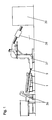
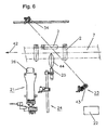
- Fig. 1 shows an overview of a device for feeding an automatic production line.
- preforms 2 are guided from a feed device 36 with a bulk material container and a climbing conveyor to a singulator 1.
- the preforms 2 are erected and placed in a single row 8.
- This single row 8 of the preforms 2 leaves the singulator 1 via a discharge rail 9 and enters a conveyor 37 with measuring and control devices, and is then fed via a transfer device 38 of a shaping device 39, for example an automatic stretch blow molding machine.
- a transfer device 38 of a shaping device 39 for example an automatic stretch blow molding machine.
- the speech in this context of preforms 2, the speech, but it is understood that the invention in an analogous manner also for singling and for aligning other substantially cylindrical Bodies having a collar or a support ring can be used.
- the components described below are arranged at the end part of the separating device 1, in the transition to the drain rail 9.
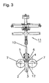
- Fig. 2 shows a side view of a liftable height guide 10 in a singulator 1, and Fig. 3 a view with a view in the conveying direction 42.
- This lift-off height guide 10 is arranged in front of the outlet end 40 of the singulator 1.
- the singling device 1 has a per se known roller conveyor 41 with two parallel rollers 7.
- the height guide 10 is attached to a lifting device 11 and by operation of lifting cylinders 20 which are pivotally connected to the height guide 10, can be raised.
- the height guide 10 is arranged above a conveyor track 16, in which the preforms 2 are conveyed in a single row 8.
- the single row 8 is formed in a known manner in a gap 12 between two counter-rotating rollers or rollers 7.
- the preforms 2 have a substantially cylindrical shape, with an end region 4 with a collar 5 and a threaded connector 6 at a first end, and a cylinder part 3 at the second end.
- the cylinder part 3 has a smaller diameter than the collar 5, so that the preform 2 is caught between the guide rollers 7 on the collar 5.
- the single row 8 is conveyed under the height guide 10 through to a drain rail 9.
- a first light barrier 14 is arranged with a first reflector 32 so that it responds when one or more of the preforms 2 are in this area of the conveyor track 16.
- a second light barrier 15 is arranged with a second reflector 33, which responds when one or more of the preforms 2 are in this area of the conveyor track 16.
- a jamming detection device 13 detects the state of the two light barriers via signal connections (not shown) and controls it accordingly via (not shown) further control connections to the lifting cylinder 20 for lifting the height guide 10 at.
- the jammed preforms 2 separate from each other and from the height guide 10 and slip through the sequence 9.
- the detachment of the preforms 2 from each other and the slipping their collar 5 together is facilitated by the fact that the preforms 2 are accelerated on the increasingly inclined flow 9 and no Preforms 2 are in the process 9, which slow this movement and separation of the preforms 2.
- the height guide 10 is raised for about half to one and a half seconds, typically about one second, and then lowered again.
- Fig. 4 shows a view of such a height guide 10 in combination with a scrubstaurad or Kickerrad 17.
- the grillstaurad 17 has paddles or blades 18, which are each provided with a slot-like recess 19, in which the height guide 10 extends.
- the tips of the blades 18 preferably extend at least as deep as the height guide 10 at its lowest point, in a range (seen in the conveying direction) in front of the height guide the tips protrude further beyond the height guide 10 out.
- the backstay wheel 17 thus detects excessively protruding preforms 2 which protrude into the area of the blades 18 or which lie on top of one another and throws them back again to the rear.
- Preforms 2 which are not detected by the backwater 17, can still lead to a jamming with the height guide 10, which is fixed as described by raising the height guide 10.
- the height guide 10 and the remindurad 17 may be adjustable together or individually by itself in height, whereby an adaptation to different geometries of the preforms 2 is possible.
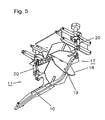
- Fig. 5 shows a perspective view of the mutual arrangement of height guide 10 and backstay 17, in which the recesses 19 and the course of the height guide 10 in the recesses 19 of the rotating blades 18 can be seen.
- the recesses 19 are deep enough so that even with raised height guide 10, this does not collide with the blades 18.
- the remindurad 17 is raised briefly together with the height guide 10.
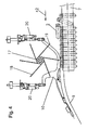
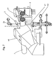
- Fig. 6 shows a side view of a first ejection device 21 in a roller conveyor.
- This ejection device 21 is arranged in the described example, in the conveying direction 42, in front of the height guide 10.
- the ejection device 21 has an ejection means 26, in this case a vertically movable body, which is vertically movable from underneath between the guide rollers 7 and pushes in such a movement located between the guide rollers 7 and incorrectly positioned preform 2 upwards.
- the ejection device 21 also has a detection device in the form of a parallel position detection device 22, which is set up to evaluate signals from a presence detector 23 and a position detector 24.
- the presence detector 23 determines whether a preform 2 is present at a predetermined measuring point of the roller conveyor 41 or the conveyor track 16.
- the presence detector 23 is for example a light barrier 43 with a reflector 34, which are arranged so that the light beam is passed through the gap 12 between the rollers 7 of the conveyor track 16 and responds when a preform 2 is present at the measuring point.
- the position detector 24 determines at the same time whether this preform 2 also hangs vertically.
- it preferably has an ultrasonic sensor 25 on, which determines a distance to the expected lower end of a preform 2 at the measuring point.
- a detection area 44, in which the ultrasonic sensor 25 responds, is shown schematically in the figure.
- the parallel position detection device 22 if this distance is too large and at the same time the presence detector 23 reports the presence of a preform 2, automatically triggers an actuation of the ejection means 26 and thereby the ejection of the misplaced preform 2.
- the location where the parallel position is controlled is upstream of the location where the ejection means 26 operates. Therefore, a delay is switched on between the time of detection of a wrong respectively horizontal preform 2 and the time of ejection. This depends on the conveying speed (depending on the size of the preforms, for example, about 15,000 to 80,000 pieces / hour) and is for example about half a second.
- the functions of the parallel position detection device 22 described herein may also be integrated into an optoelectronic sensor system having an optical image sensor 48 as shown in FIG Fig. 10 is suggested as an alternative.
- Such optoelectronic sensor systems are known per se in conveyor systems with pattern recognition.
- the ejection means 26 may comprise an asymmetrically designed ejector plunger 26 which pushes the preform 2 laterally or rearwardly in a preferred direction.
- a second ejection device with a blow-out device 27 (see Fig. 7 ), which is activated together with the ejection means 26 and the preform 2 blows away laterally.
- Fig. 7 shows a perspective view of the ejection device 21 during ejection of a conveyed body or preform 2 and a possible position of the optional blow-out device 27.
- the blow-off device 27 opposite a collecting device 45 is located. This begins the blown-off preforms 2, which are then returned to the beginning of the singulator 1.
- Fig. 8 shows a view of a pad detection device 28 with a blower 31 for removing horizontally and / or obliquely lying preforms.
- Fig. 9 shows a view of this arrangement from below.
- the support detection device 28 has a light barrier 29 with a reflector 35.
- the beam 30 of the light barrier 29 runs a little above the correct position of the preforms 2, so that it does not respond when the aligned preform 2 lie at the normal height between the guide rollers 7. If one or more of the preforms 2 lie as shown on the aligned preforms 2, they interrupt the beam 30.
- the support detection device 28 automatically triggers an air blast through the blower 31, which blows away the preforms 2 laterally.
- a plurality of air nozzles 46 distributed along the conveying direction 42 are present as part of the blow-out device 31, so that the preforms 2 are reliably detected by the air blast.
- two light barriers 29, in each case with associated air nozzles 46 are also arranged one after the other in the conveying direction 42. If, after blowing out, preforms 2 still rest on the basis of the signal of the first light barrier 29, they are detected by the second light barrier 29. This further increases the reliability of the system.
- an optical image sensor 48 see Fig. 10
- the support detection is also integrated into the system of pattern recognition and the visual barriers can then be at least partially eliminated.
- the ejection device 21 with the ejection means 26 and the support-detecting device 28 with the blow-out device 31 can be realized separately.
- the blow-out device 27 of the ejection device 21 is identical to the blow-out device 31 of the bearing-detection device 28.
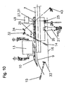
- Fig. 10 shows a side view of an embodiment of the invention with both the liftable height guide 10, and the ejector 21 and the In this illustration, the height guide 10 with the kicker 17, the ejector 21 with the associated blower 27 and the blower 31 are arranged at a preferred position along the conveyor track 16.
- the illustration also shows schematically the arrangement and orientation of the light barriers 15, 14 and 43 as well as of the ultrasonic sensor 25.
- the preforms 2 are conveyed in the conveying direction 42 through these components to the run-off rail 9. All preforms 2, which are wrong and / or disturbing, are removed or brought into a correct position by the combination of these components before the drain rail 9 from the conveyor track 16.
- Fig. 10 shows a side view of an embodiment of the invention with both the liftable height guide 10, and the ejector 21 and the In this illustration, the height guide 10 with the kicker 17, the ejector 21 with the associated blower 27 and the blower 31 are arranged at a preferred position along the conveyor track 16.
- the illustration also
- a detection device in the form of an optoelectronic sensor or an optical image sensor 48 for pattern recognition.
- This image sensor 48 comprises an optics, an image recorder and a processor and a control device for controlling the first ejection device 21 and / or the second ejection device with the blow-out device 27, 31.
- the optoelectronic image sensor 48 the light barriers 43, 29 and the ultrasonic sensor 25 omitted, since the functions of these sensors are taken over by the image sensor 48. However, they can also be used, at least partially, to improve the safety of the overall system.
Abstract
Description
Die Erfindung betrifft das Gebiet der Vereinzelung von Schüttgut, insbesondere eine Vorrichtung und ein Verfahren zum Vereinzeln von zylindrischen Körpern gemäss dem Oberbegriff der entsprechenden unabhängigen Patentansprüche.The invention relates to the field of separation of bulk material, in particular a device and a method for separating cylindrical bodies according to the preamble of the corresponding independent claims.
Üblicherweise werden Vorformlinge von PET-Flaschen, auch Preforms genannt, als Stückgut ungeordnet in grossen Behältern angeliefert und über eine Beschickungseinrichtung zu einer Vereinzelungseinrichtung geführt. Die Vereinzelungseinrichtung richtet die Vorformlinge auf und bildet eine Einzelreihe der Vorformlinge, welche die Vereinzelungseinrichtung beispielsweise über eine schräg nach unten gerichtete Rutsche, auch Ablaufschiene genannt, verlässt. Von da gelangen die Vorformlinge zu Prüf- und Fördereinrichtungen und schliesslich zu einer Streckblasmaschine, wo ihr zylindrischer Körper zu einer gewünschten Flaschenform aufgeblasen wird. Die Vorformlinge weisen typischerweise an einem offenen Ende einen Gewindekopf mit einem Gewindestutzen und einem Kragen oder Tragring auf, welcher einen grösseren Durchmesser als der übrige Zylinderteil des Vorformlings aufweist.Usually, preforms of PET bottles, also called preforms, are delivered in bulk form as bulk goods in large containers and guided via a feeding device to a separating device. The separating device straightens up the preforms and forms an individual row of the preforms, which leaves the separating device, for example via a chute pointing downwards, also called a drainage rail. From there, the preforms pass to inspection and conveying equipment and finally to a stretch blow molder where their cylindrical body is inflated to a desired bottle shape. The preforms typically have at one open end a threaded head with a threaded neck and a collar or support ring, which has a larger diameter than the rest of the cylindrical part of the preform.
Eine weitere Vorrichtung dieser Art ist aus
Aufgrund der heute geforderten hohen Förderleistung solcher Vereinzelungseinrichtungen ist eine sehr hohe Zuverlässigkeit und Störungsfreiheit gefordert, um Stillstandszeiten der nachfolgenden Anlage mit entsprechenden Folgekosten zu vermeiden. Die, bei bekannten Einrichtungen auftretenden Unterbrüche des Förderstromes von Vorformlingen und der Umstand, dass weiterhin falsch positionierte Vorformlinge vorhanden sein können, beispielsweise Vorformlinge, welche mit dem Kragen auf einem Kragen eines benachbarten Vorformlings aufliegen oder Vorformlinge, welche seitlich horizontal auf anderen Vorformlingen aufliegen, verursachen in den nachfolgenden Bereichen der Anlage Störungen und folglich Betriebsunterbrüche. Es zeigt sich, dass die Zuverlässigkeit bekannter Vereinzelungseinrichtungen den hohen Anforderungen nicht gerecht wird, und eine weitere Verbesserung der Störsicherheit erforderlich ist.Due to the high conveying capacity of such separating devices required today, a very high level of reliability and fault-free operation is required in order to avoid downtimes of the subsequent system with corresponding consequential costs. The occurring in known devices interruptions of the flow of preforms and the fact that may continue to be misplaced preforms, for example, preforms, which rest with the collar on a collar of an adjacent preform or preforms, which rest laterally horizontally on other preforms cause in the subsequent areas of the plant disturbances and consequently business interruptions. It turns out that the reliability of known singulating devices does not meet the high requirements, and a further improvement in noise immunity is required.
Es ist deshalb Aufgabe der Erfindung, eine Vereinzelungseinrichtung und ein Verfahren der eingangs genannten Art zu schaffen, welche die oben genannten Nachteile behebt. Insbesondere soll die Erfindung gewährleisten, dass bis anhin nicht feststellbare Lagefehler und auch die mit den bekannten Systemen feststellbaren Lagefehler von Vorformlingen mit hoher Zuverlässigkeit erkannt und automatisch behoben werden.It is therefore an object of the invention to provide a separating device and a method of the type mentioned, which overcomes the disadvantages mentioned above. In particular, the invention is intended to ensure that hitherto undetectable positional errors and also detectable with the known systems Positional errors of preforms with high reliability are detected and corrected automatically.
Diese Aufgabe lösen eine Vereinzelungseinrichtung für zylindrische Körper und ein Verfahren mit den Merkmalen der entsprechenden unabhängigen Patentansprüche.This object is achieved by a separating device for cylindrical bodies and a method having the features of the corresponding independent patent claims.
Die Vereinzelungseinrichtung ist auf zylindrische Körper, wie Vorformlinge für Hohlkörper ausgelegt, welche an einem ersten Ende mindestens eine Auskragung oder einen Tragring aufweisen und an einem zweiten Ende einen Durchmesser aufweisen, der geringer als der Durchmesser der Auskragung ist. Die Vereinzelungseinrichtung weist ein Paar parallel angeordneter Führungselemente auf, zwischen welchen die zylindrischen Körper aufrichtbar sind, indem die zylindrischen Körper jeweils mit der Auskragung an den Führungselementen hängen, also mit dem zweiten Ende nach unten zeigen. Die zylindrischen Körper bilden eine Einzelreihe entlang der Führungselemente und sind so zu einem Ablauf zum Weiterbefördern der zylindrischen Körper führbar.The singulating device is designed for cylindrical bodies, such as preforms for hollow bodies, which have at least one protrusion or a support ring at a first end and at a second end have a diameter which is smaller than the diameter of the protrusion. The separating device has a pair of guide elements arranged in parallel, between which the cylindrical bodies can be erected, in that the cylindrical bodies each hang with the projection on the guide elements, ie point downward with the second end. The cylindrical bodies form a single row along the guide elements and are thus feasible to a sequence for advancing the cylindrical body.
Dabei weist die Vereinzelungseinrichtung eine im Bereiche der Fuhrungselement angeordnete Detektions- und Auswurfvorrichtung auf, welche zylindrische Körper, die zwar mit der Auskragung an den Führungselementen hängen, aber deren zweites Ende nicht nach unten hängt, oder wenn zwei oder mehrere zylindrische Körper ineinander stecken bzw. verschachtelt sind, detektiert und aus der Einzelreihe auswirft.The separating device has a detection and ejection device arranged in the region of the guide element, which cylindrical bodies hang with the protrusion on the guide elements, but whose second end does not hang down, or when two or more cylindrical bodies are inserted into each other or nested, detected and ejected from the single row.
Eine solche Fehllage kann beispielsweise auftreten, wenn das untere Ende der zylindrischen Körper aufgrund von Fabrikationsfehlern oder Toleranzen zu breit ist und dadurch an den Führungselementen hängen bleibt, anstatt sich nach unten in die vertikale Lage zu drehen. Eine andere Ursache kann sein, dass zwei Vorformlinge ineinander stecken und so gemeinsam in einer horizontalen Lage zwischen den Führungselementen bleiben oder dass die ineinander steckenden zylindrischen Körper bzw. Vorformlinge schräg oder sogar korrekt nach unten hängen, aber mit dem ersten oberen Ende über ein normales Höhenprofil vorstehen. In allen Fällen wird erfasst, dass ein Vorformling vorhanden ist, aber nicht korrekt orientiert ist, und darauf das Auswerfen ausgelöst. Es ist somit eine Präsenz- wie auch eine Lagedetektion vorhanden.Such a misalignment can occur, for example, if the lower end of the cylindrical body is too wide due to manufacturing defects or tolerances and thereby gets caught on the guide elements rather than turning down into the vertical position. Another cause may be that two preforms interfit and thus remain together in a horizontal position between the guide elements or that the intermeshing cylindrical bodies or preforms hang obliquely or even correctly downwards, but with the first upper end over a normal height profile protrude. In In all cases, it is detected that a preform is present but not oriented correctly, and then the ejection is triggered. There is thus a presence as well as a location detection available.
Sowohl zur Präsenz- wie auch zur Lagedetektion sind einzelne oder Gruppen von Lichtschranken (Lichtgitter oder Lichtvorhänge) oder Zeilensensoren oder Kameras oder Reflexions-Lichttaster oder Ultraschalldistanzmesser oder mechanische Fühler denkbar, die beispielsweise seitlich oder von oben respektive unten auf die Förderbahn und die Einzelreihe der geförderten Körper ausgerichtet sind.For both presence and location detection, individual or groups of light barriers (light grids or light curtains) or line sensors or cameras or reflection light scanners or ultrasonic distance meters or mechanical sensors are conceivable, for example laterally or from above or below on the conveyor track and the individual row of conveyed Body are aligned.
Eine vorteilhafte Ausbildung der Erfindung sieht vor, dass die Detektionseinrichtung ein optoelektronischer Sensor, welcher Optik, Bildaufnehmer und Prozessor umfasst, ist und dieser optoelektronische Sensor, in der Transportrichtung der Vorformlinge gesehen, am Anfangsbereich der Teilbereichstrecke der Führungselemente, mit den Auswurfmitteln, angeordnet ist. Derartige optoelektronische Sensoren sind an sich bekannt als Kameras bzw. Bildsensoren zur Mustererkennung.An advantageous embodiment of the invention provides that the detection device is an optoelectronic sensor, which optics, image sensor and processor comprises, and this optoelectronic sensor, seen in the transport direction of the preforms, at the beginning region of the partial range of the guide elements, with the ejection means is arranged. Such optoelectronic sensors are known per se as cameras or image sensors for pattern recognition.
Erfindungsgemäss wird weiter vorgeschlagen, dass der optoelektronische Sensor mit Vergleichsmitteln ausgestattet ist, welche mittels eines Prozessors ein Steuersignal für mindestens eines der Auswurfmittel erzeugt, wenn ein Vorformling falsch auf den Führungselementen aufliegt oder zwei oder mehrere Vorformlinge ineinander verschachtelt sind.According to the invention it is further proposed that the optoelectronic sensor is equipped with comparison means, which generates a control signal for at least one of the ejection means by means of a processor, when a preform rests incorrectly on the guide elements or two or more preforms are interleaved.
Vorzugsweise weist die Auswurfvorrichtung eine Detektionseinrichtung in der Form einer Parallellage-Detektionseinrichtung mit einem Präsenzdetektor und einem Lagedetektor auf. Dabei bestimmt der Präsenzdetektor das Vorhandensein eines zylindrischen Körpers zwischen den Führungselementen, und bestimmt der Lagedetektor die Orientierung des zylindrischen Körpers. Die Parallellage-Detektionseinrichtung löst beim Vorhandensein eines zylindrischen Körpers, der eine falsche Orientierung aufweist, also im Wesentlichen parallel zu den Führungselementen liegt, das Auswerfen des zylindrischen Körpers aus.Preferably, the ejection device has a detection device in the form of a parallel position detection device with a presence detector and a position detector. In this case, the presence detector determines the presence of a cylindrical body between the guide elements, and the position detector determines the orientation of the cylindrical body. The parallel-position detection device triggers the ejection of the cylindrical body in the presence of a cylindrical body having a wrong orientation, that is substantially parallel to the guide elements.
Vorzugsweise ist der Präsenzdetektor eine Lichtschranke, insbesondere eine Lichtschranke, deren Strahl von oben nach unten oder umgekehrt durch die Einzelreihe der zylindrischen Körper führt.Preferably, the presence detector is a light barrier, in particular a light barrier, the beam of which leads from top to bottom or vice versa through the single row of cylindrical bodies.
In einer bevorzugten Ausführungsform der Erfindung detektiert der Lagedetektor ein Vorhandensein der zweiten Enden der zylindrischen Körper in einem Bereich unter den Führungselementen. Damit ist eine Detektion der Lage mit einfachen Mitteln möglich. Vorzugsweise weist der Lagedetektor einen als Distanzmesser oder Näherungsschalter ausgebildeten Ultraschallsensor auf, welcher die Distanz vom Ultraschallsensor zur erwarteten Position der zweiten Enden der zylindrischen Körper misst, und falls diese Distanz einen vorgegebenen Wert überschreitet, die falsche Orientierung des entsprechenden zylindrischen Körpers signalisiert.In a preferred embodiment of the invention, the position detector detects presence of the second ends of the cylindrical bodies in an area under the guide elements. For a detection of the situation with simple means is possible. The position detector preferably has an ultrasonic sensor in the form of a distance meter or proximity switch, which measures the distance from the ultrasonic sensor to the expected position of the second ends of the cylindrical bodies, and if this distance exceeds a predetermined value, signals the wrong orientation of the corresponding cylindrical body.
Die erste Auswurfvorrichtung weist ferner ein bewegliches Auswurfsmittel auf, welches zum Auswerfen eines falsch orientierten zylindrischen Körpers von unten her zwischen die Führungselemente hindurch fährt und so diesen zylindrischen Körper anhebt und auswirft. Zudem soll die zweite Auswurfvorrichtung eine zugeordnete Ausblasvorrichtung zum seitlichen Wegblasen des zylindrischen Körpers nach dem Anheben aufweisen.The first ejection device further comprises a movable ejection means which, for ejecting a misoriented cylindrical body, passes from underneath between the guide elements and thus raises and ejects this cylindrical body. In addition, the second ejection device should have an associated blow-out device for laterally blowing away the cylindrical body after lifting.
In einer weiteren bevorzugten Ausführungsform der Erfindung weist die Vereinzelungseinrichtung eine über der Einzelreihe angeordnete Höhenführung auf, wobei sich ein Abstand zwischen der Höhenführung und den zylindrischen Körpern, in Förderrichtung gesehen, bis zu einem vorgegebenen Abstand zu den Führungselementen verringert, wodurch vertikal vorstehende zylindrische Körper, indem sie in Förderrichtung gefördert werden, durch die Höhenführung nach unten gedrückt oder geführt werden. Dabei ist die Höhenführung mittels einer Hubvorrichtung nach Massgabe eines Auslösesignals kurzzeitig anhebbar.In a further preferred embodiment of the invention, the separating device has a height guide arranged above the individual row, wherein a distance between the height guide and the cylindrical bodies, as seen in the conveying direction, is reduced to a predetermined distance from the guide elements, whereby vertically projecting cylindrical bodies, by being conveyed in the conveying direction, are pushed or guided by the height guide down. The height guide by means of a lifting device in accordance with a trigger signal is briefly raised.
Dadurch wird es möglich, zylindrische Körper, die sich gegen respektive unter die Höhenführung verklemmt haben, vorübergehend zu befreien. Da die Verklemmung, wie sich zeigt, oftmals davon herrührt, dass ein Vorformling mit seinem Kragen auf dem Kragen eines benachbarten Vorformlings aufliegt, kann der aufliegende Vorformling nach dem Lösen der Verklemmung in die korrekte Lage abrutschen.This makes it possible to temporarily free cylindrical bodies that have jammed against respectively under the height guide. Because the deadlock, As it turns out, often stems from the fact that a preform rests with its collar on the collar of an adjacent preform, the resting preform can slip after loosening the deadlock in the correct position.
Der Abstand zwischen der Höhenführung und den zylindrischen Körpern ist zweckmässigerweise nach Massgabe der Höhe der Körper einstellbar, d.h. entsprechend der Höhe, mit der die zylindrischen Körper, wenn sie ordnungsgemäss mit ihrem Kragen an den Führungselementen hängen, vertikal über die Führungselemente hinausragen.The distance between the height guide and the cylindrical bodies is expediently adjustable according to the height of the bodies, i. according to the height with which the cylindrical bodies, when properly hung with their collars against the guide elements, protrude vertically beyond the guide elements.
In einer bevorzugten Ausführungsform der Erfindung sind die Führungselemente Rollen, insbesondere gegenläufig rotierende Rollen, und werden die zylindrischen Körper in einem Zwischenraum zwischen den Rollen gefördert. Die Vereinzelungseinrichtung basiert also auf dem Prinzip eines Rollenförderers. Die Erfindung lässt sich grundsätzlich auch mit anders gearteten Führungselementen, beispielsweise mit Schienen und beispielsweise in einem Rüttelförderer, implementieren.In a preferred embodiment of the invention, the guide elements are rollers, in particular counter-rotating rollers, and the cylindrical bodies are conveyed in a space between the rollers. The separating device is thus based on the principle of a roller conveyor. In principle, the invention can also be implemented with other types of guide elements, for example with rails and, for example, in a vibrating conveyor.
Das Anheben der Höhenführung kann durch eine Parallelbewegung oder aber auch durch eine Kippbewegung erfolgen. Das Anheben kann beispielsweise durch pneumatisch oder elektromagnetisch wirkende Aktuatoren geschehen.The lifting of the height guide can be done by a parallel movement or else by a tilting movement. The lifting can be done for example by pneumatically or electromagnetically acting actuators.
In einer weiteren bevorzugten Ausführungsform der Erfindung weist die Vereinzelungseinrichtung eine Verklemmungs-Detektionseinrichtung auf, welche dazu ausgebildet ist, ein Anstehen eines zylindrischen Körpers an der Höhenführung zu detektieren und darauf das Auslösesignal zum Anheben der Höhenführung zu erzeugen. Dadurch wird es möglich, die Höhenführung beim Vorliegen einer Verklemmung gezielt anzuheben.In a further preferred embodiment of the invention, the separating device has a jamming detection device, which is designed to detect a standing of a cylindrical body on the height guide and to generate thereon the trigger signal for raising the height guide. This makes it possible to specifically raise the height guide in the presence of jamming.
Vorzugsweise ist diese Verklemmungs-Detektionseinrichtung dazu ausgebildet, zu erfassen, ob zylindrische Körper in Förderrichtung vor der Höhenführung anstehen und ob in einem Bereich nach der Höhenführung keine zylindrischen Körper vorliegen, und wenn diese beiden Bedingungen erfüllt sind, das Auslösesignal zu erzeugen. Die Verklemmungs-Detektionseinrichtung detektiert also einen Stau in der Förderbahn der Vorformlinge im Bereich der Höhenführung, und damit implizite auch eine Verklemmung gegen die Höhenführung.Preferably, this jamming detection device is designed to detect whether cylindrical bodies are present in the conveying direction before the height guide and if there are no cylindrical bodies in an area after the height guide, and if both of these conditions are satisfied, generating the triggering signal. The jamming detection device thus detects a jam in the conveying path of the preforms in the region of the height guide, and thus implicitly a jamming against the height guide.
Die Führungselemente, der Ablauf und allfällige weitere Elemente, welche den Verlauf der Einzelreihe von zylindrischen Körpern bestimmen, werden im Folgenden zusammenfassend als Förderbahn bezeichnet.The guide elements, the sequence and any other elements which determine the course of the single row of cylindrical bodies are referred to collectively as the conveyor track .
In einer weiteren bevorzugten Ausführungsform der Erfindung weist die Verklemmungs-Detektionseinrichtung einen ersten Präsenzdetektor, insbesondere eine erste Lichtschranke, auf, welche in einem Bereich einer Förderbahn der zylindrischen Körper vor der Höhenführung das Vorhandensein von zylindrischen Körpern detektiert, und einen zweiten Präsenzdetektor, insbesondere eine zweite Lichtschranke, welche in einem Bereich der Förderbahn der zylindrischen Körper nach der Höhenführung das Vorhandensein von zylindrischen Körpern detektiert. Gemäss dieser Ausführungsform wird also ein Stau detektiert, wenn die zylindrischen Körper vor der Höhenführung anliegen und nach der Höhenführung keine anliegen. Damit ist eine Staudetektion mit einfachen Mitteln möglich.In a further preferred embodiment of the invention, the jamming detection device has a first presence detector, in particular a first light barrier, which detects the presence of cylindrical bodies in a region of a conveying path of the cylindrical bodies in front of the height guide, and a second presence detector, in particular a second Photoelectric sensor, which detects the presence of cylindrical bodies in a region of the conveying path of the cylindrical body after the height guide. According to this embodiment, therefore, a jam is detected when the cylindrical body in front of the height guide and rest after the height guide none. This is a Staudetektion possible with simple means.
In einer weiteren bevorzugten Ausführungsform der Erfindung ist einer oder sind beide Präsenzdetektoren eine Lichtschranke, und ist diese bezüglich der Förderbahn jeweils so angeordnet, dass der Strahl der Lichtschranke, wenn die zylindrischen Körper auf der Förderbahn unmittelbar aufeinander folgen, jeweils durch mehrere der zylindrischen Körper führt. Der Strahl der Lichtschranke ist vorzugsweise bezüglich der Förderbahn respektive der darin verlaufenden Einzelreihe von zylindrischen Körpern geneigt, d.h. sie verläuft in einem Winkel von weniger als 90°, vorzugsweise weniger als 70°, zur Förderrichtung der zylindrischen Körper. Die Lichtschranke kann eine Durchlichtlichtschranke (Einweg-Lichtschranke) oder eine Reflexionslichtschranke sein.In a further preferred embodiment of the invention, one or both of the presence detectors is a light barrier, and this is arranged with respect to the conveyor track such that the beam of the light barrier, when the cylindrical bodies follow each other directly on the conveyor track, respectively through several of the cylindrical body , The beam of the light barrier is preferably inclined relative to the conveyor track or the individual row of cylindrical bodies extending therein, ie it extends at an angle of less than 90 °, preferably less than 70 °, to the conveying direction of the cylindrical body. The light barrier can be a transmitted-light sensor (one-way light barrier) or a reflection light barrier.
Grundsätzlich sind anstelle von Lichtschranken auch andere Sensoren oder andere Anordnungen von Sensoren einsetzbar, welche das Vorhandensein einer Gruppe der zylindrischen Körper in einem vorgegebenen Bereich der Förderbahn detektieren. Beispielsweise sind Einzelne oder Gruppen von Lichtschranken (Lichtgitter oder Lichtvorhänge) oder Zeilensensoren oder Kameras oder Reflexions-Lichttaster oder Ultraschallsensoren oder mechanische Fühler denkbar, die beispielsweise seitlich oder von oben respektive unten auf die Förderbahn und die Einzelreihe der geförderten Körper ausgerichtet sind.In principle, other sensors or other arrangements of sensors can be used instead of light barriers, which detect the presence of a group of cylindrical bodies in a predetermined region of the conveyor track. For example, individual or groups of light barriers (light curtains or light curtains) or line sensors or cameras or reflection light sensors or ultrasonic sensors or mechanical sensors are conceivable, for example, are aligned laterally or from above or below on the conveyor track and the single row of subsidized body.
In einer weiteren bevorzugten Ausführungsform der Erfindung ist die Höhenführung im Bereich eines Rückstaurades (oder Kickerrades) angeordnet, und weisen Schaufeln des rotierenden Rückstaurades jeweils eine Ausnehmung auf, welche mit der Form der Höhenführung korrespondiert: Dabei ragen die Schaufeln in einem Bereich, in welchem die Höhenführung noch nicht wirksam ist, nach unten über die Höhenführung hinaus. Damit ist eine besonders platzsparende Kombination des Rückstaurades mit der Höhenführung möglich. Grundsätzlich ist es aber auch möglich, das Rückstaurad vor der Höhenführung entlang der Förderbahn anzuordnen. Diese Kombination hat den Vorteil, dass weiter hervor ragende und lose aufliegende zylindrische Körper durch das Rückstaurad erfasst und entgegen der Förderrichtung nach hinten geworfen werden, und weniger weit hervor ragende zylindrische Körper zwar nicht durch das Rückstaurad, aber anschliessend durch die Höhenführung erfasst werden. In Förderrichtung gesehen ist also zuerst das Rückstaurad und dann die Höhenführung wirksam. In beiden Fällen ragen die Schaufeln des Rückstaurades an der tiefsten Stelle vorzugsweise weiter nach unten als die Höhenführung. Obschon damit theoretisch das Rückstaurad alle zylindrischen Körper erfassen sollte, die an der Höhenführung anstehen würden, zeigt die Praxis doch, dass sich auch dann ab und zu die zylindrischen Körper an der Höhenführung verklemmen.In a further preferred embodiment of the invention, the height guide in the region of a Rückstaurades (or Kickerrades) is arranged, and have blades of the rotating Rückstaurades each have a recess which corresponds to the shape of the height guide: In this case, the blades protrude in an area in which the Height guide is not yet effective, down beyond the height guide out. This is a particularly space-saving combination of Rückstaurades with the height guide possible. In principle, it is also possible to arrange the Rückstaurad before the height guide along the conveyor track. This combination has the advantage that further protruding and loose cylindrical body detected by the Rückstaurad and thrown back against the conveying direction, and not far protruding cylindrical body are not detected by the Rückstaurad, but then by the height guide. Seen in the conveying direction so first the Rückstaurad and then the height guide is effective. In both cases, the blades of the Rückstaurades project at the lowest point preferably further down than the height guide. Although theoretically the Rückstaurad should capture all cylindrical body, which would be present at the height guide, the practice shows that even then and then the cylindrical body jammed on the height guide.
In einer weiteren bevorzugten Ausführungsform der Erfindung weist die Vereinzelungseinrichtung ferner eine Auflagedetektionseinrichtung auf, welche erfasst, ob ein zylindrischer Körper auf den in der Einzelreihe geförderten zylindrischen Körper aufliegt oder seitlich anliegt. Wenn dies der Fall ist, wird eine zugeordnete Ausblasvorrichtung zum seitlichen Wegblasen eines zylindrischen Körpers von den Führungselementen respektive der Einzelreihe aktiviert.In a further preferred embodiment of the invention, the separating device further comprises a bearing detection device, which detects whether a cylindrical body on the conveyed in the single row cylindrical body rests or rests on the side. If this is the case, an associated blower for lateral blowing away a cylindrical body of the guide elements or the single row is activated.
Vorzugsweise weist die Auflagedetektionseinrichtung eine Lichtschranke auf, deren Strahl im Wesentlichen horizontal und im Winkel, vorzugsweise im Wesentlichen senkrecht, zum Verlauf der Führungselemente respektive der Einzelreihe verläuft. Die Höhe des Strahls ist so eingestellt, dass die Lichtschranke bei übereinander aufliegenden zylindrischen Körpern anspricht. Falls also die zylindrischen Körper in der Normallage sind, verläuft der Strahl oberhalb der zylindrischen Körper, und die Lichtschranke spricht nicht an. Die Lichtschranke kann an einer Stelle der Förderbahn angeordnet sein, an welcher auch das Ausblasen stattfindet. Dann wird das Ausblasen ohne wesentliche Verzögerung nach dem Ansprechen der Lichtschranke ausgelöst. Falls das Ausblasen erst an einer späteren Stelle geschieht, wird es entsprechend der Fördergeschwindigkeit erst eine bestimmte Zeit nach dem Ansprechen der Lichtschranke ausgelöst.Preferably, the support detection device has a light barrier whose beam extends substantially horizontally and at an angle, preferably substantially perpendicular, to the course of the guide elements or the individual row. The height of the beam is set so that the light barrier responds to cylindrical bodies lying one above the other. Thus, if the cylindrical bodies are in the normal position, the beam passes above the cylindrical body and the photocell does not respond. The light barrier may be arranged at a location of the conveyor track on which also the purging takes place. Then the blowing is triggered without significant delay after the response of the photocell. If the blowing out takes place at a later point in time, it will only be triggered a certain time after the light barrier has responded in accordance with the conveying speed.
In einer weiteren bevorzugten Ausführungsform der Erfindung ist die Ausblasvorrichtung, welche der Auswurfvorrichtung zugeordnet ist, mit der Ausblasvorrichtung, welche der Auflagedetektionseinrichtung zugeordnet ist, identisch. Dadurch ergibt sich eine Vereinfachung der Gesamtvorrichtung bei kombinierter erhöhter Funktionalität.In a further preferred embodiment of the invention, the blow-out device, which is associated with the ejection device, is identical to the blow-out device, which is assigned to the support-detection device. This results in a simplification of the overall device combined with increased functionality.
In einer weiteren bevorzugten Ausführungsform der Erfindung weist die Vereinzelungsvorrichtung sowohl die Auswurfvorrichtung als auch ein Kickerrad und eine verstellbare Höhenführung auf. Optional kann zudem auch eine seitliche Ausblasvorrichtung zur Elimination von horizontal aufliegenden Körpern vorliegen. Mit dieser Kombination von Elementen können verschieden geartete Fehllagen in komplementärer Weise erkannt und behoben werden, wodurch sich insgesamt eine sehr hohe Zuverlässigkeit ergibt.In a further preferred embodiment of the invention, the separating device has both the ejection device and a kicker wheel and an adjustable height guide. Optionally, there may also be a lateral blow-out device for the elimination of horizontally lying bodies. With this combination of elements different types of misfires can be detected and remedied in a complementary manner, resulting in a very high overall reliability.
In einer weiteren bevorzugten Ausführungsform der Erfindung verwenden die Auswurfvorrichtung und die verstellbare Höhenführung mindestens einen Sensor gemeinsam. So kann beispielsweise eine Lichtschranke, welche als Präsenzdetektor der Auswurfvorrichtung wirkt, auch zur Detektion eines Staus vor der Höhenführung verwendet werden. Unter Umständen wird bei der Auswertung der Sensorsignale für die Höhenführung die Transportzeit zwischen Auswurfvorrichtung und Höhenführung berücksichtigt, und ob die Auswurfvorrichtung kürzlich ausgelöst wurde.In a further preferred embodiment of the invention, the ejection device and the adjustable height guide use at least one sensor in common. Thus, for example, a light barrier, which acts as a presence detector of the ejection device, can also be used to detect a traffic jam prior to altitude guidance. Under certain circumstances, when evaluating the sensor signals for the height guidance, the transport time between ejection device and height guidance is taken into account, and whether the ejection device was triggered recently.
Die oben beschriebenen Vorrichtungen eignen sich grundsätzlich nicht nur für das Ausrichten von Vorformlingen, sondern von allen Stückgütern, welche einen Stütz- oder Tragring oder eine Auflagefläche oder einen Kragen aufweisen.The devices described above are in principle not only suitable for the alignment of preforms, but of all general cargo, which have a support or support ring or a support surface or a collar.
Weitere bevorzugte Ausführungsformen gehen aus den abhängigen Patentansprüchen hervor. Dabei sind Merkmale der Verfahrensansprüche sinngemäss mit jenen der Vorrichtungsansprüche kombinierbar und umgekehrt.Further preferred embodiments emerge from the dependent claims. Characteristics of the method claims are analogously combined with those of the device claims and vice versa.
Im Folgenden wird der Erfindungsgegenstand anhand von bevorzugten Ausführungsbeispielen, welche in den beiliegenden Zeichnungen dargestellt sind, näher erläutert. Es zeigen jeweils schematisch:
- Fig. 1
- einen Überblick über eine Einrichtung zum Beschicken einer automatischen Produktionsstrasse,
- Fig. 2
- eine Seitenansicht einer anhebbaren Höhenführung in einem Rollenförderer,
- Fig. 3
- eine Ansicht der Höhenführung mit Blick in Förderrichtung,
- Fig. 4
- eine Ansicht einer solchen Höhenführung in Kombination mit einem Rückstaurad,
- Fig. 5
- eine perspektivische Ansicht der Anordnung von Höhenführung und Rückstaurad,
- Fig. 6
- eine Seitenansicht einer Auswurfvorrichtung in einem Rollenförderer,
- Fig. 7
- eine perspektivische Ansicht der Auswurfvorrichtung beim Auswerfen eines geförderten Körpers,
- Fig. 8
- eine Ansicht einer Ausblasvorrichtung zum Entfernen aufliegender Vorformlinge,
- Fig. 9
- eine Ansicht der Anordnung der
Figur 8 von unten, und - Fig. 10
- eine Seitenansicht eines Rollenförderers mit einer anhebbaren Höhenführung und einer Auswurfvorrichtung mit einer Ausblasvorrichtung.
- Fig. 1
- an overview of a device for feeding an automatic production line,
- Fig. 2
- a side view of a liftable height guide in a roller conveyor,
- Fig. 3
- a view of the height guide with a view in the conveying direction,
- Fig. 4
- a view of such a height guide in combination with a Rückstaurad,
- Fig. 5
- a perspective view of the arrangement of height guide and Rückstaurad,
- Fig. 6
- a side view of an ejector in a roller conveyor,
- Fig. 7
- a perspective view of the ejector when ejecting a subsidized body,
- Fig. 8
- a view of a blower for removing overlying preforms,
- Fig. 9
- a view of the arrangement of
FIG. 8 from below, and - Fig. 10
- a side view of a roller conveyor with a liftable height guide and an ejector with a blower.
Die in den Zeichnungen verwendeten Bezugszeichen und deren Bedeutung sind in der Bezugszeichenliste zusammengefasst aufgelistet. Grundsätzlich sind in den Figuren gleiche Teile mit gleichen Bezugszeichen versehen.The reference numerals used in the drawings and their meaning are listed in the list of reference numerals. Basically, the same parts are provided with the same reference numerals in the figures.
Die Einzelreihe 8 wird unter der Höhenführung 10 hindurch zu einer Ablaufschiene 9 gefördert. In einem Bereich - in Förderrichtung 42 betrachtet - vor der Höhenführung 10 ist eine erste Lichtschranke 14 mit einem ersten Reflektor 32 angeordnet, so dass sie anspricht, wenn sich einer oder mehrere der Vorformlinge 2 in diesem Bereich der Förderbahn 16 befinden. In einem Bereich nach der Höhenführung 10, also beispielsweise beim Ablauf 9, ist eine zweite Lichtschranke 15 mit einem zweiten Reflektor 33 angeordnet, welche anspricht, wenn sich einer oder mehrere der Vorformlinge 2 in diesem Bereich der Förderbahn 16 befinden. Eine Verklemmungs-Detektionseinrichtung 13 erfasst über (nicht eingezeichnet) Signalverbindungen den Zustand der beiden Lichtschranken und steuert dem entsprechend über (nicht eingezeichnet) weitere Steuerverbindungen die Hubzylinder 20 zum Anheben der Höhenführung 10 an.The
Dies geschieht in folgender Weise: Wenn, wie in der
Das Auswurfsmittel 26 kann einen asymmetrisch gestalteten Auswurfstössel 26 aufweisen, welcher den Vorformling 2 in eine bevorzugte Richtung seitlich oder nach hinten wegstösst. Alternativ oder zusätzlich ist eine zweite Auswurfvorrichtung mit einer Ausblasvorrichtung 27 (siehe
Grundsätzlich sind die Auswurfvorrichtung 21 mit dem Auswurfsmittel 26 und die Auflagedetektionseinrichtung 28 mit der Ausblasvorrichtung 31 separat realisierbar. In der in den
- 11
- Vereinzelungseinrichtungseparating device
- 22
- zylindrischer Körper (Vorformling)cylindrical body (preform)
- 33
- Zylinderteil, zweites Ende (2)Cylinder part, second end (2)
- 44
- Endbereich, erstes Ende (2)End area, first end (2)
- 55
- Kragen (2)Collar (2)
- 66
- Gewindestutzen (2)Threaded connector (2)
- 77
- Führungsrollen (1)Guide rollers (1)
- 88th
- EinzelreiheSingle row
- 99
- Ablaufschienedrain channel
- 1010
- Höhenführung (1)Height guide (1)
- 1111
- Hubvorrichtung (1)Lifting device (1)
- 1212
- Zwischenraumgap
- 1313
- Verklemmungs-Detektionseinrichtung (1)Jamming detection device (1)
- 1414
- erste Lichtschranke (13)first photocell (13)
- 1515
- zweite Lichtschranke (13)second photocell (13)
- 1616
- Förderbahnconveyor track
- 1717
- Rückstaurad, Kickerrad (1)Backwheel, Kicker Wheel (1)
- 1818
- Schaufel (17)Shovel (17)
- 1919
- Ausnehmung (18)Recess (18)
- 2020
- Hubzylinder (11)Lifting cylinder (11)
- 2121
- Auswurfvorrichtung (1)Ejector device (1)
- 2222
- Parallellage-Detektionseinrichtung (21)Parallel position detection device (21)
- 2323
- Präsenzdetektor (22)Presence Detector (22)
- 2424
- Lagedetektor (22)Position detector (22)
- 2525
- Ultraschallsensor (24)Ultrasonic sensor (24)
- 2626
- Auswurfsmittel (21)Rejects (21)
- 2727
- Ausblasvorrichtung (21)Blower (21)
- 2828
- Auflagedetektionseinrichtung (1)Support detection device (1)
- 2929
- Lichtschranke (28)Photocell (28)
- 3030
- Strahlbeam
- 3131
- Ausblasvorrichtung (28)Blower (28)
- 3232
- Reflektor (14)Reflector (14)
- 3333
- Reflektor (15)Reflector (15)
- 3434
- Reflektor (22)Reflector (22)
- 3535
- Reflektor (29)Reflector (29)
- 3636
- Beschickungseinrichtungfeeder
- 3737
- FördereinrichtungConveyor
- 3838
- Übernahmeeinrichtungtransfer device
- 3939
- Formgebungseinrichtungshaping device
- 4040
- Austrittsende (1)Exit end (1)
- 4141
- Rollenförderer (1)Roller conveyor (1)
- 4242
- Förderrichtungconveying direction
- 4343
- Lichtschranke (22)Photocell (22)
- 4444
- Erfassungsbereichdetection range
- 4545
- Auffangvorrichtungcatcher
- 4646
- Luftdüsen (31)Air nozzles (31)
- 4747
- 4848
- optischer Bildsensor (Kamera)optical image sensor (camera)
Claims (22)
- A separating device (1) for cylindrical bodies (2), such as preforms for hollow bodies, which have at least one projection (5) at a first end and have a diameter which is smaller than the diameter of the projection (5) at a second end, wherein the separating device (1) has a pair of parallel-arranged guide elements (7) between which the cylindrical bodies (2) may be aligned in that the cylindrical bodies (2) each hang on the guide elements (7) by means of the projection (5) and the cylindrical bodies (2) form a single row (8) along the guide elements (7) and may thus be guided to an outlet (9) for conveying the cylindrical bodies (2) further, wherein the separating device comprises a detection device which detects incorrectly positioned and/or interlocked preforms (2) and is equipped with a control device for ejection devices, characterised in that the detection device is arranged in the region of the guide elements (7), a first ejection device (21) with an ejection means (26) engaging between the guide elements (7) from below for ejecting preforms (2) and a second ejection device with a blow-ejection device (27, 31) for ejecting preforms (2) by blowing them away from the guide elements (7) are arranged in the region of the guide elements (7).
- A separating device (1) according to Claim 1, characterised in that the detection device is an optoelectronic sensor which comprises an optical system, image recorder and processor, and this optoelectronic sensor, as seen in the transport direction of the preforms (2), is arranged at the starting region of the sub-region path of the guide elements (7) having the ejection means (21, 27, 31).
- A separating device (1) according to Claim 2, characterised in that the optoelectronic sensor is equipped with a comparison means which generates a control signal for at least one of the ejection means (21, 27, 31) by means of a processor when a preform (2) is resting incorrectly on the guide elements (7) or two or more preforms (2) are mutually interlocked.
- A separating device (1) according to Claim 1, characterised in that the detection device has a parallel-position detection device (22) with a presence detector (23) and a position detector (24), wherein the presence detector (23) determines the presence of a cylindrical body (2) between the guide elements (7) and the position detector (24) determines the orientation of the cylindrical body (2) and, if an incorrectly orientated cylindrical body (2) is present, the parallel-position detection device (22) triggers the ejection of the cylindrical body (2).
- A separating device (1) according to Claim 4, characterised in that the presence detector (23) is a light barrier, and in particular the beam of the light barrier (23) is directed from the top down, or vice versa, through the single row (8) of cylindrical bodies (2).
- A separating device (1) according to Claim 4 or 5, characterised in that the position detector (24) detects the presence of the second ends (3) of the cylindrical bodies (2) in a region below the guide elements (7).
- A separating device (1) according to one of Claims 4 to 6, characterised in that the position detector (24) has an ultrasound sensor (25) which measures the distance from the ultrasound sensor (25) to the expected position of the second ends (3) of the cylindrical bodies (2) and, if this distance exceeds a predetermined value, the position detector (24) signals an incorrect orientation of the corresponding cylindrical body (2).
- A separating device (1) according to one of Claims 1 to 7, characterised in that the first ejection device (21) has a movable ejection means (26) which, to eject an incorrectly orientated cylindrical body (2), moves through between the guide elements (7) from below and thus lifts this cylindrical body (2) and ejects it.
- A separating element (1) according to one of Claims 1 to 8, characterised in that the second ejection device has an associated blow-ejection device (27) for blowing a cylindrical body (2) away laterally after it has been lifted.
- A separating element (1) according to one of the preceding claims, characterised in that the separating device (1) further has a resting detection device (28) which detects whether a cylindrical body (2) is resting on the cylindrical bodies (2) conveyed in the single row (8) and, if this is the case, activates an associated blow-ejection device (31) for blowing a cylindrical body (2) away laterally from the guide elements (7) or the single row (8).
- A separating device (1) according to Claim 10, characterised in that the resting detection device (28) has a light barrier (29) whereof the beam (30) extends substantially horizontally and at an angle to the course of the guide elements (7) or the single row (8) and whereof the height is set so that the light barrier (28) responds when cylindrical bodies (2) are resting on top of one another.
- A separating device (1) according to Claim 10 or 11 in dependence on Claim 9, characterised in that the blow-ejection device (27) which is associated with the second ejection device is identical to the blow-ejection device (31) which is associated with the resting detection device (28).
- A separating device (1) according to one of the preceding claims, characterised in that the separating device (1) has a vertical guide (10) arranged above the single row (8), wherein a spacing between the vertical guide (10) and the cylindrical bodies (2), as seen in the conveying direction, decreases to a predetermined spacing from the guide elements (7), as a result of which vertically protruding cylindrical bodies (2), when they are conveyed in the conveying direction, are pressed downwards by the vertical guide (10) and wherein the vertical guide (10) may be lifted briefly by means of a lifting device (11) in accordance with a trigger signal.
- A separating device (1) according to Claim 13, characterised in that the guide elements (7) are rollers, in particular counter-rotating rollers, and the cylindrical bodies (2) are conveyed in a clearance (12) between the rollers (7).
- A separating device (1) according to Claim 13 or 14, characterised in that the separating device (1) is a jam detection device (13) which is designed to detect when one or more cylindrical bodies (2) are waiting at the vertical guide (10) and then generate the trigger signal for lifting the vertical guide (10).
- A separating device (1) according to Claim 15, characterised in that the jam detection device (13) is designed to detect whether cylindrical bodies (2) are waiting upstream of the vertical guide (10) in the conveying direction and whether no cylindrical bodies (2) are present in a region downstream of the vertical guide (10) and, if these two conditions are fulfilled, to generate the trigger signal.
- A separating device (1) according to Claim 15 or 16, characterised in that the jam detection device (13) has a first presence detector, in particular a first light barrier (14), which detects the presence of cylindrical bodies (2) in a region of a conveying path (16) of the cylindrical bodies (2) upstream of the vertical guide (10), and a second presence detector, in particular a second light barrier (15), which detects the presence of cylindrical bodies (2) in a region of the conveying path (16) of the cylindrical bodies (2) downstream of the vertical guide (10).
- A separating device (1) according to Claim 17, characterised in that one or both presence detectors is or are a light barrier (14), (15) and is or are arranged with respect to the conveying path (16) in each case such that the beam of the light barrier (14), (15) is directed in each case through a plurality of the cylindrical bodies (2) when the cylindrical bodies (2) directly follow one another on the conveying path (16).
- A separating device (1) according to one of Claims 13 to 18, characterised in that the vertical guide (10) is arranged in the region of a back-pressure wheel (17) and blades (18) of the back-pressure wheel (17) each have an opening (19) which corresponds to the shape of the vertical guide (10), and the blades (18) project downwards beyond the vertical guide (10) at least in a region in which the vertical guide (10) is not yet effective.
- A process for separating cylindrical bodies (2), for example preforms for hollow bodies, which have at least one projection (5) at a first end and a diameter which is smaller than the diameter of the projection (5) at a second end, wherein the cylindrical bodies (2) may be aligned between a pair of parallel-arranged guide elements (7) in that the cylindrical bodies (2) each hang on the guide elements (7) by means of the projection (5) and the cylindrical bodies (2) form a single row (8) along the guide elements (7) and are thus guided to an outlet (9) for conveying the cylindrical bodies (2) further, wherein, before the transfer of the cylindrical bodies (2) to the outlet (9), presence and position detection is carried out simultaneously in the region of the guide elements (7) and it is determined whether a cylindrical body (2) is present at a predetermined point along the guide elements but does not hang down on the projection (5) or two or more cylindrical bodies (2) are mutually interlocked and, if this is the case, the cylindrical body (2) is expelled upwards out of the single row (8) by ejection means engaging between the guide elements and blown away by a blow-ejection device.
- A process according to Claim 20, characterised in that the cylindrical bodies (2) are conveyed through below a vertical guide (10) arranged above the single row (8), wherein a spacing between the vertical guide (10) and the cylindrical bodies (2), as seen in the conveying direction, decreases to a predetermined spacing from the guide elements (7) as a result of which vertically protruding cylindrical bodies (2) are pressed downwards by the vertical guide (10) as they are conveyed in the conveying direction, and wherein the vertical guide (10) is lifted briefly by means of a lifting device (11) in accordance with a trigger signal.
- A process according to Claim 20 or 21, characterised in that, in the region of the guide elements (7), it is additionally determined whether a cylindrical body (2) is resting on the cylindrical bodies (2) conveyed in the single row (8) and, if this is the case, the cylindrical body (2) is blown away from the guide elements (7) or the single row (8) and, in addition, above the guide elements (7) and approximately at a right angle to the conveying direction of the cylindrical bodies (2), a detection signal is emitted and, if an incorrectly positioned body (2) is detected, an air jet is generated.
Applications Claiming Priority (2)
| Application Number | Priority Date | Filing Date | Title |
|---|---|---|---|
| CH01110/08A CH699223A1 (en) | 2008-07-17 | 2008-07-17 | Device and method for separating cylindrical bodies. |
| PCT/CH2009/000256 WO2010006462A1 (en) | 2008-07-17 | 2009-07-15 | Apparatus for, and method of, separating cylindrical bodies |
Publications (2)
| Publication Number | Publication Date |
|---|---|
| EP2303733A1 EP2303733A1 (en) | 2011-04-06 |
| EP2303733B1 true EP2303733B1 (en) | 2012-01-04 |
Family
ID=40303713
Family Applications (1)
| Application Number | Title | Priority Date | Filing Date |
|---|---|---|---|
| EP09797340A Active EP2303733B1 (en) | 2008-07-17 | 2009-07-15 | Apparatus for, and method of, separating cylindrical bodies |
Country Status (6)
| Country | Link |
|---|---|
| US (1) | US8522956B2 (en) |
| EP (1) | EP2303733B1 (en) |
| CN (1) | CN102099269B (en) |
| AT (1) | ATE539986T1 (en) |
| CH (1) | CH699223A1 (en) |
| WO (1) | WO2010006462A1 (en) |
Cited By (2)
| Publication number | Priority date | Publication date | Assignee | Title |
|---|---|---|---|---|
| EP2650101A1 (en) * | 2012-04-10 | 2013-10-16 | Krones AG | Roller conveyor for plastic preforms |
| DE102012011762A1 (en) * | 2012-06-15 | 2013-12-19 | Khs Corpoplast Gmbh | Separating device for preforms with a device for separating out incorrectly positioned preforms |
Families Citing this family (19)
| Publication number | Priority date | Publication date | Assignee | Title |
|---|---|---|---|---|
| CH699222A1 (en) * | 2008-07-17 | 2010-01-29 | M Tanner Ag | Device and method for separating cylindrical bodies. |
| CH702406A1 (en) * | 2009-12-11 | 2011-06-15 | M Tanner Ag | Apparatus for sorting out incorrectly positioned cylindrical bodies in a separating and conveying device. |
| DE102010008367A1 (en) * | 2010-02-17 | 2011-08-18 | Krones Ag, 93073 | Roller sorter and sorting method for sorting preforms and transport device with such roller sorter |
| CH704401A1 (en) * | 2011-01-28 | 2012-07-31 | M Tanner Ag | Conveyor for cylindrical bodies, with inclined in conveying direction delivery rails. |
| DE102011016858A1 (en) | 2011-04-13 | 2012-10-18 | Krones Aktiengesellschaft | Device for transporting and sorting plastic preforms, has transport unit which transports plastic performs along predetermined transport path, where transport unit has two guide elements that support plastic preforms |
| DE102012101653A1 (en) * | 2012-02-29 | 2013-08-29 | Krones Ag | Preform transport with individual ejection option |
| DE102012017699A1 (en) * | 2012-09-07 | 2014-03-13 | Khs Corpoplast Gmbh | Separating device for preforms |
| US9533833B2 (en) * | 2013-08-08 | 2017-01-03 | Norwalt Design, Inc. | Unjamming system for product feeders |
| DE102014102203A1 (en) | 2014-02-20 | 2015-08-20 | Krones Ag | Method for transporting plastic preforms, device for transporting plastic preforms and circuit arrangement for such a device |
| EP3157729B1 (en) * | 2014-06-18 | 2018-08-01 | Sacmi Imola S.C. | System for feeding preforms |
| DE102014010862B4 (en) | 2014-07-25 | 2021-01-07 | Khs Corpoplast Gmbh | Method and device for transporting preforms |
| DE102015205984A1 (en) * | 2015-04-02 | 2016-10-06 | Krones Aktiengesellschaft | Method and guide system for the transport of containers or container components in industrial plants for container production and / or product filling |
| DE102015215366A1 (en) * | 2015-08-12 | 2017-02-16 | Robert Bosch Gmbh | Apparatus and method for feeding products |
| CH711442A1 (en) * | 2015-08-21 | 2017-02-28 | M Tanner Ag | Device for immobilizing preforms for plastic containers. |
| EP3239077A1 (en) | 2016-04-29 | 2017-11-01 | M. Tanner AG | Device for loading a subsequent processing installation with of esters of carbamic acids as bulk material objects |
| FR3051780A1 (en) * | 2016-05-25 | 2017-12-01 | Sidel Participations | METHOD FOR UNLOCKING THE HOLLOW BODY SCROLL IN A SLIDE CONVEYOR |
| IT201600128336A1 (en) * | 2016-12-19 | 2018-06-19 | True Keg S R L | A SYSTEM FOR THE FEEDING OF PRE-FORM IN POLYMERIC MATERIALS TO A STIROSOFFIAGIACO MACHINE |
| US11548736B2 (en) * | 2019-08-01 | 2023-01-10 | Mgs Machine Corporation | System and method for organizing and feeding cylindrical products from a bulk supply to a product take away conveyance |
| DE102022114820A1 (en) * | 2022-06-13 | 2023-12-14 | Krones Aktiengesellschaft | Roll sorter DirectLink |
Family Cites Families (10)
| Publication number | Priority date | Publication date | Assignee | Title |
|---|---|---|---|---|
| US3506840A (en) * | 1967-09-08 | 1970-04-14 | Anchor Hocking Glass Corp | Down-ware rejector system |
| US4223778A (en) * | 1978-05-12 | 1980-09-23 | Owens-Illinois, Inc. | Parison handling assemblies and methods for handling parisons |
| US4440286A (en) * | 1981-03-13 | 1984-04-03 | Avdel Limited | Orientating device |
| FR2556273B1 (en) * | 1983-12-09 | 1986-07-25 | Pont A Mousson | PROCESS FOR MANUFACTURING PLASTIC BOTTLES FROM BLANKS AND BLANK OBTAINED FROM THIS PROCESS |
| JP2991000B2 (en) * | 1993-04-22 | 1999-12-13 | 神鋼電機株式会社 | Parts feeder |
| JPH09156751A (en) | 1995-12-06 | 1997-06-17 | Ykk Corp | Parts aligning feeder |
| IT1305277B1 (en) * | 1998-10-20 | 2001-04-19 | Sipa Spa | DEVICE FOR THE IDENTIFICATION AND ELIMINATION OF PREFORMS HOOKED BY A CONTINUOUS TRANSFER LINE. |
| FR2816297B1 (en) | 2000-11-03 | 2003-01-10 | Sidel Sa | PREFORM FEEDING SYSTEM, IN PARTICULAR FOR A CONTAINER BLOWING MACHINE |
| FR2864050B1 (en) * | 2003-12-23 | 2007-04-06 | Sidel Sa | PREFORM FEEDING SYSTEM HAVING A DEVICE FOR SELECTIVELY ELIMINATING MALLED POSITIONED PREFORMS |
| US7322458B1 (en) * | 2006-08-02 | 2008-01-29 | Norwalt Design Inc. | Orienting and feeding apparatus for manufacturing line |
-
2008
- 2008-07-17 CH CH01110/08A patent/CH699223A1/en not_active Application Discontinuation
-
2009
- 2009-07-15 US US13/002,754 patent/US8522956B2/en active Active
- 2009-07-15 CN CN200980128043.5A patent/CN102099269B/en not_active Expired - Fee Related
- 2009-07-15 WO PCT/CH2009/000256 patent/WO2010006462A1/en active Application Filing
- 2009-07-15 AT AT09797340T patent/ATE539986T1/en active
- 2009-07-15 EP EP09797340A patent/EP2303733B1/en active Active
Cited By (2)
| Publication number | Priority date | Publication date | Assignee | Title |
|---|---|---|---|---|
| EP2650101A1 (en) * | 2012-04-10 | 2013-10-16 | Krones AG | Roller conveyor for plastic preforms |
| DE102012011762A1 (en) * | 2012-06-15 | 2013-12-19 | Khs Corpoplast Gmbh | Separating device for preforms with a device for separating out incorrectly positioned preforms |
Also Published As
| Publication number | Publication date |
|---|---|
| US20110120833A1 (en) | 2011-05-26 |
| CN102099269B (en) | 2014-08-13 |
| WO2010006462A1 (en) | 2010-01-21 |
| CN102099269A (en) | 2011-06-15 |
| ATE539986T1 (en) | 2012-01-15 |
| EP2303733A1 (en) | 2011-04-06 |
| US8522956B2 (en) | 2013-09-03 |
| CH699223A1 (en) | 2010-01-29 |
Similar Documents
| Publication | Publication Date | Title |
|---|---|---|
| EP2303733B1 (en) | Apparatus for, and method of, separating cylindrical bodies | |
| EP2303732B1 (en) | Apparatus for, and method of, separating cylindrical bodies | |
| EP2509894B1 (en) | Device for sorting out incorrectly positioned cylindrical bodies in a separating and conveying unit | |
| EP2845715B1 (en) | Inspection and ejector unit | |
| WO2012163978A2 (en) | Method and apparatus for transporting articles to a station | |
| EP0996531B1 (en) | Method and device for producing plastic hollow bodies | |
| EP0699396B1 (en) | Apparatus for transport filter sticks | |
| EP2554356B1 (en) | Apparatus and method for conveying and sorting plastic preforms | |
| EP2295156A2 (en) | Transportation device with means for detecting fallen articles and method for control of same | |
| DE102009003844B4 (en) | Apparatus and method for discharging objects from a moving conveyor | |
| EP3453648A1 (en) | Inlet device | |
| EP2765558A1 (en) | Coin separation system | |
| DE102016101027B4 (en) | Rotary tablet press | |
| DE102011016858A1 (en) | Device for transporting and sorting plastic preforms, has transport unit which transports plastic performs along predetermined transport path, where transport unit has two guide elements that support plastic preforms | |
| EP3199333B1 (en) | Rotary press for tablets | |
| DE3211543C2 (en) | Treatment machine for objects, in particular filling or labeling machines for bottles | |
| EP3028963A1 (en) | Device for orienting a container | |
| DE3914360C2 (en) | ||
| DE102020134010B3 (en) | FREE GLASS PACKAGING | |
| EP3571146B1 (en) | Sorting method for hollow bodies and sorting device | |
| EP4339136A1 (en) | Separating device and method for separating preforms | |
| WO2024078662A1 (en) | Device for conveying and separating workpieces | |
| DE202019106352U1 (en) | Sternradeinheit | |
| WO2020020493A1 (en) | Method and device for supplying a container mass flow to at least one lane | |
| DD268439A1 (en) | DEVICE FOR ALIGNING BOTTLES |
Legal Events
| Date | Code | Title | Description |
|---|---|---|---|
| PUAI | Public reference made under article 153(3) epc to a published international application that has entered the european phase |
Free format text: ORIGINAL CODE: 0009012 |
|
| 17P | Request for examination filed |
Effective date: 20101221 |
|
| AK | Designated contracting states |
Kind code of ref document: A1 Designated state(s): AT BE BG CH CY CZ DE DK EE ES FI FR GB GR HR HU IE IS IT LI LT LU LV MC MK MT NL NO PL PT RO SE SI SK SM TR |
|
| AX | Request for extension of the european patent |
Extension state: AL BA RS |
|
| GRAP | Despatch of communication of intention to grant a patent |
Free format text: ORIGINAL CODE: EPIDOSNIGR1 |
|
| DAX | Request for extension of the european patent (deleted) | ||
| GRAS | Grant fee paid |
Free format text: ORIGINAL CODE: EPIDOSNIGR3 |
|
| GRAA | (expected) grant |
Free format text: ORIGINAL CODE: 0009210 |
|
| AK | Designated contracting states |
Kind code of ref document: B1 Designated state(s): AT BE BG CH CY CZ DE DK EE ES FI FR GB GR HR HU IE IS IT LI LT LU LV MC MK MT NL NO PL PT RO SE SI SK SM TR |
|
| REG | Reference to a national code |
Ref country code: GB Ref legal event code: FG4D Free format text: NOT ENGLISH |
|
| REG | Reference to a national code |
Ref country code: CH Ref legal event code: EP |
|
| REG | Reference to a national code |
Ref country code: AT Ref legal event code: REF Ref document number: 539986 Country of ref document: AT Kind code of ref document: T Effective date: 20120115 |
|
| REG | Reference to a national code |
Ref country code: IE Ref legal event code: FG4D |
|
| REG | Reference to a national code |
Ref country code: CH Ref legal event code: NV Representative=s name: FREI PATENTANWALTSBUERO AG |
|
| REG | Reference to a national code |
Ref country code: DE Ref legal event code: R096 Ref document number: 502009002437 Country of ref document: DE Effective date: 20120308 |
|
| REG | Reference to a national code |
Ref country code: NL Ref legal event code: VDEP Effective date: 20120104 |
|
| PG25 | Lapsed in a contracting state [announced via postgrant information from national office to epo] |
Ref country code: SI Free format text: LAPSE BECAUSE OF FAILURE TO SUBMIT A TRANSLATION OF THE DESCRIPTION OR TO PAY THE FEE WITHIN THE PRESCRIBED TIME-LIMIT Effective date: 20120104 |
|
| REG | Reference to a national code |
Ref country code: CH Ref legal event code: NV Representative=s name: PATENTANWAELTE SCHAAD, BALASS, MENZL & PARTNER AG |
|
| LTIE | Lt: invalidation of european patent or patent extension |
Effective date: 20120104 |
|
| PG25 | Lapsed in a contracting state [announced via postgrant information from national office to epo] |
Ref country code: NO Free format text: LAPSE BECAUSE OF FAILURE TO SUBMIT A TRANSLATION OF THE DESCRIPTION OR TO PAY THE FEE WITHIN THE PRESCRIBED TIME-LIMIT Effective date: 20120404 Ref country code: HR Free format text: LAPSE BECAUSE OF FAILURE TO SUBMIT A TRANSLATION OF THE DESCRIPTION OR TO PAY THE FEE WITHIN THE PRESCRIBED TIME-LIMIT Effective date: 20120104 Ref country code: NL Free format text: LAPSE BECAUSE OF FAILURE TO SUBMIT A TRANSLATION OF THE DESCRIPTION OR TO PAY THE FEE WITHIN THE PRESCRIBED TIME-LIMIT Effective date: 20120104 Ref country code: IS Free format text: LAPSE BECAUSE OF FAILURE TO SUBMIT A TRANSLATION OF THE DESCRIPTION OR TO PAY THE FEE WITHIN THE PRESCRIBED TIME-LIMIT Effective date: 20120504 Ref country code: BG Free format text: LAPSE BECAUSE OF FAILURE TO SUBMIT A TRANSLATION OF THE DESCRIPTION OR TO PAY THE FEE WITHIN THE PRESCRIBED TIME-LIMIT Effective date: 20120404 Ref country code: LT Free format text: LAPSE BECAUSE OF FAILURE TO SUBMIT A TRANSLATION OF THE DESCRIPTION OR TO PAY THE FEE WITHIN THE PRESCRIBED TIME-LIMIT Effective date: 20120104 |
|
| REG | Reference to a national code |
Ref country code: IE Ref legal event code: FD4D |
|
| PG25 | Lapsed in a contracting state [announced via postgrant information from national office to epo] |
Ref country code: PT Free format text: LAPSE BECAUSE OF FAILURE TO SUBMIT A TRANSLATION OF THE DESCRIPTION OR TO PAY THE FEE WITHIN THE PRESCRIBED TIME-LIMIT Effective date: 20120504 Ref country code: FI Free format text: LAPSE BECAUSE OF FAILURE TO SUBMIT A TRANSLATION OF THE DESCRIPTION OR TO PAY THE FEE WITHIN THE PRESCRIBED TIME-LIMIT Effective date: 20120104 Ref country code: GR Free format text: LAPSE BECAUSE OF FAILURE TO SUBMIT A TRANSLATION OF THE DESCRIPTION OR TO PAY THE FEE WITHIN THE PRESCRIBED TIME-LIMIT Effective date: 20120405 Ref country code: LV Free format text: LAPSE BECAUSE OF FAILURE TO SUBMIT A TRANSLATION OF THE DESCRIPTION OR TO PAY THE FEE WITHIN THE PRESCRIBED TIME-LIMIT Effective date: 20120104 Ref country code: PL Free format text: LAPSE BECAUSE OF FAILURE TO SUBMIT A TRANSLATION OF THE DESCRIPTION OR TO PAY THE FEE WITHIN THE PRESCRIBED TIME-LIMIT Effective date: 20120104 |
|
| PG25 | Lapsed in a contracting state [announced via postgrant information from national office to epo] |
Ref country code: CY Free format text: LAPSE BECAUSE OF FAILURE TO SUBMIT A TRANSLATION OF THE DESCRIPTION OR TO PAY THE FEE WITHIN THE PRESCRIBED TIME-LIMIT Effective date: 20120104 |
|
| PG25 | Lapsed in a contracting state [announced via postgrant information from national office to epo] |
Ref country code: DK Free format text: LAPSE BECAUSE OF FAILURE TO SUBMIT A TRANSLATION OF THE DESCRIPTION OR TO PAY THE FEE WITHIN THE PRESCRIBED TIME-LIMIT Effective date: 20120104 Ref country code: CZ Free format text: LAPSE BECAUSE OF FAILURE TO SUBMIT A TRANSLATION OF THE DESCRIPTION OR TO PAY THE FEE WITHIN THE PRESCRIBED TIME-LIMIT Effective date: 20120104 Ref country code: SE Free format text: LAPSE BECAUSE OF FAILURE TO SUBMIT A TRANSLATION OF THE DESCRIPTION OR TO PAY THE FEE WITHIN THE PRESCRIBED TIME-LIMIT Effective date: 20120104 Ref country code: EE Free format text: LAPSE BECAUSE OF FAILURE TO SUBMIT A TRANSLATION OF THE DESCRIPTION OR TO PAY THE FEE WITHIN THE PRESCRIBED TIME-LIMIT Effective date: 20120104 Ref country code: IE Free format text: LAPSE BECAUSE OF FAILURE TO SUBMIT A TRANSLATION OF THE DESCRIPTION OR TO PAY THE FEE WITHIN THE PRESCRIBED TIME-LIMIT Effective date: 20120104 Ref country code: RO Free format text: LAPSE BECAUSE OF FAILURE TO SUBMIT A TRANSLATION OF THE DESCRIPTION OR TO PAY THE FEE WITHIN THE PRESCRIBED TIME-LIMIT Effective date: 20120104 |
|
| PLBE | No opposition filed within time limit |
Free format text: ORIGINAL CODE: 0009261 |
|
| STAA | Information on the status of an ep patent application or granted ep patent |
Free format text: STATUS: NO OPPOSITION FILED WITHIN TIME LIMIT |
|
| PG25 | Lapsed in a contracting state [announced via postgrant information from national office to epo] |
Ref country code: SK Free format text: LAPSE BECAUSE OF FAILURE TO SUBMIT A TRANSLATION OF THE DESCRIPTION OR TO PAY THE FEE WITHIN THE PRESCRIBED TIME-LIMIT Effective date: 20120104 |
|
| 26N | No opposition filed |
Effective date: 20121005 |
|
| BERE | Be: lapsed |
Owner name: M. TANNER A.G. Effective date: 20120731 |
|
| REG | Reference to a national code |
Ref country code: DE Ref legal event code: R097 Ref document number: 502009002437 Country of ref document: DE Effective date: 20121005 |
|
| PG25 | Lapsed in a contracting state [announced via postgrant information from national office to epo] |
Ref country code: MC Free format text: LAPSE BECAUSE OF NON-PAYMENT OF DUE FEES Effective date: 20120731 Ref country code: MK Free format text: LAPSE BECAUSE OF FAILURE TO SUBMIT A TRANSLATION OF THE DESCRIPTION OR TO PAY THE FEE WITHIN THE PRESCRIBED TIME-LIMIT Effective date: 20120104 |
|
| PG25 | Lapsed in a contracting state [announced via postgrant information from national office to epo] |
Ref country code: ES Free format text: LAPSE BECAUSE OF FAILURE TO SUBMIT A TRANSLATION OF THE DESCRIPTION OR TO PAY THE FEE WITHIN THE PRESCRIBED TIME-LIMIT Effective date: 20120415 |
|
| PG25 | Lapsed in a contracting state [announced via postgrant information from national office to epo] |
Ref country code: BE Free format text: LAPSE BECAUSE OF NON-PAYMENT OF DUE FEES Effective date: 20120731 |
|
| PG25 | Lapsed in a contracting state [announced via postgrant information from national office to epo] |
Ref country code: MT Free format text: LAPSE BECAUSE OF FAILURE TO SUBMIT A TRANSLATION OF THE DESCRIPTION OR TO PAY THE FEE WITHIN THE PRESCRIBED TIME-LIMIT Effective date: 20120104 |
|
| PGFP | Annual fee paid to national office [announced via postgrant information from national office to epo] |
Ref country code: GB Payment date: 20130719 Year of fee payment: 5 |
|
| PG25 | Lapsed in a contracting state [announced via postgrant information from national office to epo] |
Ref country code: TR Free format text: LAPSE BECAUSE OF FAILURE TO SUBMIT A TRANSLATION OF THE DESCRIPTION OR TO PAY THE FEE WITHIN THE PRESCRIBED TIME-LIMIT Effective date: 20120104 |
|
| PG25 | Lapsed in a contracting state [announced via postgrant information from national office to epo] |
Ref country code: LU Free format text: LAPSE BECAUSE OF NON-PAYMENT OF DUE FEES Effective date: 20120715 Ref country code: SM Free format text: LAPSE BECAUSE OF FAILURE TO SUBMIT A TRANSLATION OF THE DESCRIPTION OR TO PAY THE FEE WITHIN THE PRESCRIBED TIME-LIMIT Effective date: 20120104 |
|
| PG25 | Lapsed in a contracting state [announced via postgrant information from national office to epo] |
Ref country code: HU Free format text: LAPSE BECAUSE OF FAILURE TO SUBMIT A TRANSLATION OF THE DESCRIPTION OR TO PAY THE FEE WITHIN THE PRESCRIBED TIME-LIMIT Effective date: 20090715 |
|
| GBPC | Gb: european patent ceased through non-payment of renewal fee |
Effective date: 20140715 |
|
| PG25 | Lapsed in a contracting state [announced via postgrant information from national office to epo] |
Ref country code: GB Free format text: LAPSE BECAUSE OF NON-PAYMENT OF DUE FEES Effective date: 20140715 |
|
| REG | Reference to a national code |
Ref country code: FR Ref legal event code: PLFP Year of fee payment: 8 |
|
| REG | Reference to a national code |
Ref country code: FR Ref legal event code: PLFP Year of fee payment: 9 |
|
| REG | Reference to a national code |
Ref country code: FR Ref legal event code: PLFP Year of fee payment: 10 |
|
| REG | Reference to a national code |
Ref country code: DE Ref legal event code: R081 Ref document number: 502009002437 Country of ref document: DE Owner name: M. TANNER AG, CH Free format text: FORMER OWNER: M. TANNER AG, ILLNAU, CH |
|
| PGFP | Annual fee paid to national office [announced via postgrant information from national office to epo] |
Ref country code: IT Payment date: 20230724 Year of fee payment: 15 Ref country code: CH Payment date: 20230801 Year of fee payment: 15 Ref country code: AT Payment date: 20230720 Year of fee payment: 15 |
|
| PGFP | Annual fee paid to national office [announced via postgrant information from national office to epo] |
Ref country code: FR Payment date: 20230725 Year of fee payment: 15 Ref country code: DE Payment date: 20230719 Year of fee payment: 15 |