EP2303080B1 - Food processing machine - Google Patents
Food processing machine Download PDFInfo
- Publication number
- EP2303080B1 EP2303080B1 EP09788864A EP09788864A EP2303080B1 EP 2303080 B1 EP2303080 B1 EP 2303080B1 EP 09788864 A EP09788864 A EP 09788864A EP 09788864 A EP09788864 A EP 09788864A EP 2303080 B1 EP2303080 B1 EP 2303080B1
- Authority
- EP
- European Patent Office
- Prior art keywords
- container
- cover
- food processing
- sidewall
- spout
- Prior art date
- Legal status (The legal status is an assumption and is not a legal conclusion. Google has not performed a legal analysis and makes no representation as to the accuracy of the status listed.)
- Not-in-force
Links
- 235000013305 food Nutrition 0.000 title claims description 26
- 239000007788 liquid Substances 0.000 claims description 24
- 230000002093 peripheral effect Effects 0.000 claims 2
- 239000000463 material Substances 0.000 description 4
- 229920002725 thermoplastic elastomer Polymers 0.000 description 4
- 230000000712 assembly Effects 0.000 description 3
- 238000000429 assembly Methods 0.000 description 3
- 238000001816 cooling Methods 0.000 description 2
- 229920001971 elastomer Polymers 0.000 description 2
- NJPPVKZQTLUDBO-UHFFFAOYSA-N novaluron Chemical compound C1=C(Cl)C(OC(F)(F)C(OC(F)(F)F)F)=CC=C1NC(=O)NC(=O)C1=C(F)C=CC=C1F NJPPVKZQTLUDBO-UHFFFAOYSA-N 0.000 description 2
- 229920001169 thermoplastic Polymers 0.000 description 2
- 239000004416 thermosoftening plastic Substances 0.000 description 2
- 229920001634 Copolyester Polymers 0.000 description 1
- 230000004913 activation Effects 0.000 description 1
- 235000013361 beverage Nutrition 0.000 description 1
- 229920001400 block copolymer Polymers 0.000 description 1
- 230000015556 catabolic process Effects 0.000 description 1
- 239000000806 elastomer Substances 0.000 description 1
- 239000013536 elastomeric material Substances 0.000 description 1
- 235000021268 hot food Nutrition 0.000 description 1
- 238000000034 method Methods 0.000 description 1
- 239000000203 mixture Substances 0.000 description 1
- 238000012986 modification Methods 0.000 description 1
- 230000004048 modification Effects 0.000 description 1
- 239000004033 plastic Substances 0.000 description 1
- 229920003023 plastic Polymers 0.000 description 1
- 229920000515 polycarbonate Polymers 0.000 description 1
- 239000004417 polycarbonate Substances 0.000 description 1
- 239000012858 resilient material Substances 0.000 description 1
- 239000005060 rubber Substances 0.000 description 1
- 239000007779 soft material Substances 0.000 description 1
- 235000014347 soups Nutrition 0.000 description 1
- 238000003756 stirring Methods 0.000 description 1
- 229920006342 thermoplastic vulcanizate Polymers 0.000 description 1
Images




Classifications
-
- A—HUMAN NECESSITIES
- A47—FURNITURE; DOMESTIC ARTICLES OR APPLIANCES; COFFEE MILLS; SPICE MILLS; SUCTION CLEANERS IN GENERAL
- A47J—KITCHEN EQUIPMENT; COFFEE MILLS; SPICE MILLS; APPARATUS FOR MAKING BEVERAGES
- A47J43/00—Implements for preparing or holding food, not provided for in other groups of this subclass
- A47J43/04—Machines for domestic use not covered elsewhere, e.g. for grinding, mixing, stirring, kneading, emulsifying, whipping or beating foodstuffs, e.g. power-driven
- A47J43/046—Machines for domestic use not covered elsewhere, e.g. for grinding, mixing, stirring, kneading, emulsifying, whipping or beating foodstuffs, e.g. power-driven with tools driven from the bottom side
-
- A—HUMAN NECESSITIES
- A47—FURNITURE; DOMESTIC ARTICLES OR APPLIANCES; COFFEE MILLS; SPICE MILLS; SUCTION CLEANERS IN GENERAL
- A47J—KITCHEN EQUIPMENT; COFFEE MILLS; SPICE MILLS; APPARATUS FOR MAKING BEVERAGES
- A47J43/00—Implements for preparing or holding food, not provided for in other groups of this subclass
- A47J43/04—Machines for domestic use not covered elsewhere, e.g. for grinding, mixing, stirring, kneading, emulsifying, whipping or beating foodstuffs, e.g. power-driven
- A47J43/07—Parts or details, e.g. mixing tools, whipping tools
- A47J43/075—Safety devices
- A47J43/0761—Safety devices for machines with tools driven from the lower side
Definitions
- This invention relates to a food processing machine of the type which utilizes a mixing blade to blend food products in a container. More particularly, this invention relates to the manner in which the cover of the container is attached to and detached from the container, and the manner in which hot food products can be safely dispensed from the container. In addition, this invention relates to the manner in which the motor which rotates the blade is protected from moisture.
- Most food processing equipment that blends foods in a container by means of a rotating blade includes a cover for the container.
- Such covers must be securely attached to the container during the mixing of the foods, and yet, at the same time, be removable without requiring undo force.
- Some prior art covers are made of a flexible material and include a slot which receives a lip of the container thereby holding the cover on the container. In some of these covers, a tab extends from the cover and is lifted to release the cover from the container. However, after multiple flexures, this release system of the prior art tends to breakdown such that the tab becomes overflexed resulting in the inability of the cover to latch onto the container.
- US publication US2007201306A1 teaches a blender base that could be used with a food processor container, a blender container and a single use beverage container.
- the container includes a blade unit for different types of blades.
- the implement can be operated upon the user selection of pre-defined functions.
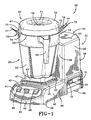
- a food processing assembly is shown in Fig. 1 and is generally indicated by the numeral 20.
- Assembly 20 includes three basic component parts, a base member indicated generally by the numeral 21, a blender container indicated generally by the numeral 22, and a cover for the container 21 indicated generally by the numeral 23.
- Base member 21 is provided with feet 24 and includes a motor housing portion generally indicated by the numeral 25 and a platform portion generally indicated by the numeral 26.
- Housing portion 25 includes a top wall 27, opposed front and rear walls, 28 and 29 respectively, and opposed side walls 30 which together with a bottom surface (not shown) house a motor.
- One of the side walls 30 is provided with a recess 31 which can receive any of several controls such as a circuit breaker 32, a master power switch 33 or the like. Because these controls are recessed, they are protected from accidental contact.
- the rear wall 29 of housing portion 25 may be provided with an opening 34 for the passage of a power cord for the motor.
- Rear wall 29 is also provided with a plurality of air intake slots or louvers 35.
- a fan in housing portion 25 draws cooling air into housing portion 25 through louvers 35, and past the motor. The air is then expelled from housing portion 25 through slots 36 in the bottom surface of base member 21.
- a gutter, generally indicated by the numeral 37, is formed above and around louvers 35. Gutter 37 is designed to protect any liquid that might be on housing portion 25, and in particular that might be running down rear wall 29, from being received by the air intake louvers 35.
- Gutter 37 thus includes a top portion 38 positioned above louvers 35 to collect any such liquid, and opposed side portions 39 which allow the liquids to leave rear wall 29. As such, any liquids which might have otherwise been drawn into housing portion 25 through louvers 35, to the detriment of the motor contained therein, is drained away from the louvers 35 and the motor is thereby protected.
- Platform portion 26 of base member 21 includes a front wall 40 having a control panel 41, opposed side walls 42, and a top surface 43 extending between front wall 40, side walls 42, and front wall 28 of housing portion 25.
- the back of platform portion 26 is open and communicates with the inside of housing portion 25.
- Control panel 41 may include any number of conventional controls such as an on/off switch 44, a motor speed control 45, and/or a motor pulsing button 46.
- the top surface 43 of platform portion 26 is provided with a pedestal 47 which carries four locator pads 48 (two shown) to receive the corners of the bottom of container 22, and is provided with a coupler 49 to attach the motor to the container 22 as will be hereinafter described.
- Pedestal 47 is also provided with at least one drainage channel 50 to direct any present liquid away from coupler 49.
- Blender container 22 may be made of a clear plastic material, such as a copolyester or polycarbonate material, and includes a bottom surface 51 and a sidewall or sidewalls 52 extending upwardly therefrom to form an open top. A rim 53 extends outwardly from the periphery of the open top at the top of the sidewalls 52. Sidewalls 52 are shown as being generally circular in configuration and thus, in essence, only one continuous sidewall is shown. However, the container 22 could take on any configuration, such as square and therefore having four sidewalls, without departing from the concepts of the present invention.
- a clear plastic material such as a copolyester or polycarbonate material
- a generally circular sidewall 52 is provided, as shown, it may be provided with a plurality of generally vertically extending ribs 54 which generally provide strength to the sidewall 52, enhance the mixing of foods, and also are aesthetically pleasing.
- the addition of strength to the sidewall 52 and the enhancement of mixing can be important particularly when large volume containers 22 are provided.
- food processing assembly 20 may have particular applicability to the commercial environment of a hospital or an assisted living establishment. As such, a container 21 of a capacity of a gallon and a half or more may be provided.
- a blender blade 55 ( Fig. 5 ) is conventionally carried on a shaft 56 near the bottom surface 51 of container 22.
- a base skirt 52 extends downwardly from bottom surface 51 and is generally rectangular in nature so as to fit over locator pads 48 on base platform 26.
- shaft 56 extends through bottom surface 51 and has a conventional splined end 58 which is adapted to be received by coupler 49.
- a number of structural ribs and the like, generally indicated by the numeral 59, are provided within skirt 57 and around splined shaft end 58.
- housing portion 25 can then rotate shaft 56, preferably through a belt drive extending from housing portion 25 into platform portion 26 through the open back thereof.
- Container 22 is shown as having a handle 60 carried near the top of sidewall 52 and a pouring spout 61 is formed at the top of sidewall 52 at a location generally diametrically or otherwise opposed to handle 60.
- a heat shield generally indicated by the numeral 62, made of an insulating, soft material such as a flexible thermoplastic elastomer, is formed on container sidewall 52 at the area of spout 61.
- heat shield 62 includes a body portion 63 which is attached to a portion of container sidewall 52 at an area under spout 61 extending from spout 61 to the bottom of sidewall 52 terminating at skirt 57. Body portion also extends approximately one quarter of the circumference of sidewall 52.
- Heat shield 62 also includes a safety flap 64 spaced from body portion 63, and a generally horizontal top portion 65 interconnects flap 64 and body portion 63. Top portion 65 thus extends outwardly from near the top of body portion 63 at the sides of pouring spout 61.
- heat shield 62 may also be extended, as at 66, to cover the bottom and the outer sides of the spout 61.
- container 22 is intended to be quite large, as previously described, it may be difficult to pour liquid through the spout 61 by only holding the handle 60, particularly if container 22 is full of liquid. In this situation, the usual tactic of the user is to grasp the handle 60 with one hand and place the other hand on the sidewall 52 under the spout 61. However, if container 22 is holding a hot liquid, as may often be the case, in the prior art such a procedure could prove harmful or at least uncomfortable to the user's hand which could either be irritated or burned by contact with the sidewall or by drippings from the spout. However, the heat shield 62 of the present invention prevents such harm. As can be seen in Figs.
- heat shield body portion 63 and flap 64 there is a space between heat shield body portion 63 and flap 64 within or under which the user may place his or her hand to assist in pouring of hot liquid through spout 61.
- body portion 63 protects the hand against heat from the liquid within the container
- flap 64 protects the hand from hot drippings from spout 61.
- Container cover 23 is formed of a resilient or elastomeric material such as most known thermoplastic elastomers (TPE's).
- TPE's include, for example, thermoplastic olofin rubbers, thermoplastic vulcanizates, and thermoplastic elastic block copolymers. These materials are particularly suited for cover 23 as they all inhibit the elastomer properties required for cover 23.
- Cover 23 is configured to match the configuration of the open top of container 22 and thus, in the embodiment shown, it includes a round sidewall 67 having a shoulder 68 which is adapted to rest on the rim 53 of container 22.
- the lower portion 69 of sidewall 67 extending below shoulder 68 is adapted to snuggly fit within the inside of container 22, and as shown in Fig. 6 , at the area of spout 61, sidewall portion 69 closes spout 61.
- Cover 23 includes a top portion 70 extending between its sidewalls 67 which is dished out, as at 71, and provided with a central aperture 72.
- Aperture 72 is normally closed by a plug (not shown), but when open provides access to the inside of the container 22 should stirring or the like be desired.
- Cover 23 is shown as having two diametrically opposed tab assemblies, generally indicated by the numeral 73, located at the area of shoulder 68. While two tab assemblies 73 are shown, it will be evident that the present invention would only require one tab assembly 73 or, alternatively, more than two could be provided.
- Each tab assembly 73 includes a body portion 74 connected to the sidewall 67 of cover 23, as by strip 75 formed adjacent to shoulder 68.
- a notch 76 is formed in body portion 74 below strip 75, and a handle portion 77 of tab assembly 73 extends upwardly angularly outwardly from body portion 74 at an angle of preferably about forty-five degrees. Handle portion 77 is provided with a finger hole 78 therethrough.
- Cover 23 is shown as being fully engaged by container 22 in Fig. 7 .
- container rim 53 is received in cover notch 76 and the lower portion 69 of cover sidewall 67 is engaging the inside of container sidewall 52.
- Fig. 8 shows the manner in which cover 23 may be released from container 22. That is, the handle portion 77 of one of the tab assemblies 73 is lifted from the chain line position to the full line position. This can be conveniently accomplished by placing one's finger in hole 78, but such is not required as long as handle 77 is being lifted. The upward movement of handle 77 only slightly flexes strip 75 until the rim 53 is released from the notch 76.
- handle 77 also moves the cover 23 upwardly so that it may then be removed from container 22 as shown in Fig. 9 .
- a handle was flexed to unlatch the cover from the container but had to be continued to be flexed to remove the cover. But in the present invention, the single slight movement accomplishes both functions.
Landscapes
- Engineering & Computer Science (AREA)
- Mechanical Engineering (AREA)
- Food Science & Technology (AREA)
- Food-Manufacturing Devices (AREA)
- Closures For Containers (AREA)
- Cookers (AREA)
Description
- This invention relates to a food processing machine of the type which utilizes a mixing blade to blend food products in a container. More particularly, this invention relates to the manner in which the cover of the container is attached to and detached from the container, and the manner in which hot food products can be safely dispensed from the container. In addition, this invention relates to the manner in which the motor which rotates the blade is protected from moisture.
- Most food processing equipment that blends foods in a container by means of a rotating blade includes a cover for the container. Such covers must be securely attached to the container during the mixing of the foods, and yet, at the same time, be removable without requiring undo force. Some prior art covers are made of a flexible material and include a slot which receives a lip of the container thereby holding the cover on the container. In some of these covers, a tab extends from the cover and is lifted to release the cover from the container. However, after multiple flexures, this release system of the prior art tends to breakdown such that the tab becomes overflexed resulting in the inability of the cover to latch onto the container.
- An additional problem arises when the equipment is being used to mix large volumes of hot liquids, such as soups or the like. Normally such liquids are dispensed from the container by lifting the container by its handle and pouring the liquid out through a spout. However, if the equipment includes a very large container, for example, of more than one gallon in volume, as might be used in institutions such as hospitals or the like, dispensing of the heavy hot liquid can be problematic. For example, such might require the use of two hands, one lifting the handle and the other gripping the container under the spout. But such not only exposes that hand to the temperature of the hot liquid in the container but also exposes that hand to the possibility of hot drippings from the spout.
- Moreover, to blend these large volumes of liquids require a large motor which rotates the mixing blade. These motors generate a great deal of heat and must be cooled usually by drawing cooling air into the motor housing and expelling that air through outlet ports. However, inasmuch as the processor is often being used in an environment with liquids close by, it is important to make certain that no liquids are drawn into the motor housing. For example, if the motor housing has just been cleaned, extreme care must be taken to assure that it is dry so that no liquids will be drawn into the motor housing.
- US publication
US2007201306A1 teaches a blender base that could be used with a food processor container, a blender container and a single use beverage container. The container includes a blade unit for different types of blades. The implement can be operated upon the user selection of pre-defined functions. - The need exists, therefore, for food processing equipment which is not plagued with these problems of the prior art.
- It is thus an object of one aspect of the present invention to provide food processing equipment with a container and a cover that can be securely attached to the container and yet be easily removed.
- It is another object of that aspect of the present invention to provide the food processing equipment, as above, in which the cover is removed from the container by flexing a handle but which will not become overflexed after multiple uses.
- It is an object of another aspect of the present invention to provide food processing equipment with a large container from which hot liquids can be readily dispensed without allowing the heat from the liquids to irritate or harm the user.
- It is an object of an additional aspect of the present invention to provide food processing equipment which is powered by an air cooled motor in a housing and which prohibits liquid from entering the housing with the air.
- These and other objects of the present invention, as well as the advantages thereof over existing prior art forms, which will become apparent from the description to follow, are accomplished by the improvements hereinafter described and claimed.
- The food processing assembly made in accordance with the present invention comprises the features of the appended claims.
- A preferred exemplary food processing device made according to the concepts of the present invention is shown by way of example in the accompanying drawings without attempting to show all the various forms and modifications in which the invention might be embodied, the invention being measured by the appended claims and not by the details of the specification.
-
-
Fig. 1 is a perspective view of a food processing assembly including a base member housing a motor, a container, and a cover made in accordance with the present invention. -
Fig. 2 is a bottom perspective view of the container and cover. -
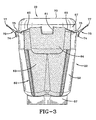
Fig. 3 is a front elevational view of the container and cover. -
Fig. 4 is a side elevational view of the container and cover. -
Fig. 5 is a top plan view of the container and cover. -
Fig. 6 is a fragmentary sectional view taken substantially along line 6-6 ofFig. 5 . -
Fig. 7 is a fragmentary sectional view taken substantially along line 7-7 ofFig. 5 . -
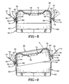
Fig. 8 is a fragmentary sectional view likeFig. 7 but showing the cover as it is being released from container. -
Fig. 9 is a fragmentary sectional view likeFigs. 7 and8 and showing the cover being released from the container sequentially followingFig. 8 . -
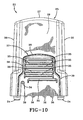
Fig. 10 is a rear elevational view of the base member. -
Fig. 11 is a partially sectioned side elevational view of the base member. - A food processing assembly is shown in
Fig. 1 and is generally indicated by thenumeral 20.Assembly 20 includes three basic component parts, a base member indicated generally by thenumeral 21, a blender container indicated generally by thenumeral 22, and a cover for thecontainer 21 indicated generally by thenumeral 23. -
Base member 21 is provided withfeet 24 and includes a motor housing portion generally indicated by thenumeral 25 and a platform portion generally indicated by thenumeral 26.Housing portion 25 includes atop wall 27, opposed front and rear walls, 28 and 29 respectively, and opposedside walls 30 which together with a bottom surface (not shown) house a motor. One of theside walls 30 is provided with arecess 31 which can receive any of several controls such as acircuit breaker 32, amaster power switch 33 or the like. Because these controls are recessed, they are protected from accidental contact. - As shown in
Fig. 10 , therear wall 29 ofhousing portion 25 may be provided with anopening 34 for the passage of a power cord for the motor.Rear wall 29 is also provided with a plurality of air intake slots orlouvers 35. A fan inhousing portion 25 draws cooling air intohousing portion 25 throughlouvers 35, and past the motor. The air is then expelled fromhousing portion 25 throughslots 36 in the bottom surface ofbase member 21. A gutter, generally indicated by thenumeral 37, is formed above and aroundlouvers 35. Gutter 37 is designed to protect any liquid that might be onhousing portion 25, and in particular that might be running downrear wall 29, from being received by theair intake louvers 35.Gutter 37 thus includes atop portion 38 positioned abovelouvers 35 to collect any such liquid, and opposedside portions 39 which allow the liquids to leaverear wall 29. As such, any liquids which might have otherwise been drawn intohousing portion 25 throughlouvers 35, to the detriment of the motor contained therein, is drained away from thelouvers 35 and the motor is thereby protected. -
Platform portion 26 ofbase member 21 includes afront wall 40 having acontrol panel 41, opposedside walls 42, and atop surface 43 extending betweenfront wall 40,side walls 42, andfront wall 28 ofhousing portion 25. The back ofplatform portion 26 is open and communicates with the inside ofhousing portion 25.Control panel 41 may include any number of conventional controls such as an on/off switch 44, amotor speed control 45, and/or amotor pulsing button 46. - As best seen in
Fig. 11 , thetop surface 43 ofplatform portion 26 is provided with apedestal 47 which carries four locator pads 48 (two shown) to receive the corners of the bottom ofcontainer 22, and is provided with acoupler 49 to attach the motor to thecontainer 22 as will be hereinafter described.Pedestal 47 is also provided with at least onedrainage channel 50 to direct any present liquid away fromcoupler 49. -
Blender container 22 may be made of a clear plastic material, such as a copolyester or polycarbonate material, and includes abottom surface 51 and a sidewall orsidewalls 52 extending upwardly therefrom to form an open top. Arim 53 extends outwardly from the periphery of the open top at the top of thesidewalls 52.Sidewalls 52 are shown as being generally circular in configuration and thus, in essence, only one continuous sidewall is shown. However, thecontainer 22 could take on any configuration, such as square and therefore having four sidewalls, without departing from the concepts of the present invention. If a generallycircular sidewall 52 is provided, as shown, it may be provided with a plurality of generally vertically extending ribs 54 which generally provide strength to thesidewall 52, enhance the mixing of foods, and also are aesthetically pleasing. The addition of strength to thesidewall 52 and the enhancement of mixing can be important particularly whenlarge volume containers 22 are provided. For example, it is contemplated thatfood processing assembly 20 may have particular applicability to the commercial environment of a hospital or an assisted living establishment. As such, acontainer 21 of a capacity of a gallon and a half or more may be provided. - A blender blade 55 (
Fig. 5 ) is conventionally carried on ashaft 56 near thebottom surface 51 ofcontainer 22. Abase skirt 52 extends downwardly frombottom surface 51 and is generally rectangular in nature so as to fit overlocator pads 48 onbase platform 26. As shown inFig. 2 ,shaft 56 extends throughbottom surface 51 and has a conventionalsplined end 58 which is adapted to be received bycoupler 49. A number of structural ribs and the like, generally indicated by the numeral 59, are provided withinskirt 57 and aroundsplined shaft end 58. Onceshaft 56 is so connected tocoupler 49, activation in the motor will rotateblade 55 is a conventional fashion. If, as previously described, thecontainer 22 is of a large volume, a large motor must be provided inhousing portion 25 which is why theside walls 30 ofhousing portion 25 are shown as having a significant height. The motor inhousing portion 25 can then rotateshaft 56, preferably through a belt drive extending fromhousing portion 25 intoplatform portion 26 through the open back thereof. -
Container 22 is shown as having ahandle 60 carried near the top ofsidewall 52 and a pouringspout 61 is formed at the top ofsidewall 52 at a location generally diametrically or otherwise opposed to handle 60. A heat shield, generally indicated by the numeral 62, made of an insulating, soft material such as a flexible thermoplastic elastomer, is formed oncontainer sidewall 52 at the area ofspout 61. Specifically,heat shield 62 includes abody portion 63 which is attached to a portion ofcontainer sidewall 52 at an area underspout 61 extending fromspout 61 to the bottom ofsidewall 52 terminating atskirt 57. Body portion also extends approximately one quarter of the circumference ofsidewall 52.Heat shield 62 also includes asafety flap 64 spaced frombody portion 63, and a generally horizontaltop portion 65interconnects flap 64 andbody portion 63.Top portion 65 thus extends outwardly from near the top ofbody portion 63 at the sides of pouringspout 61. In addition,heat shield 62 may also be extended, as at 66, to cover the bottom and the outer sides of thespout 61. - Because
container 22 is intended to be quite large, as previously described, it may be difficult to pour liquid through thespout 61 by only holding thehandle 60, particularly ifcontainer 22 is full of liquid. In this situation, the usual tactic of the user is to grasp thehandle 60 with one hand and place the other hand on thesidewall 52 under thespout 61. However, ifcontainer 22 is holding a hot liquid, as may often be the case, in the prior art such a procedure could prove harmful or at least uncomfortable to the user's hand which could either be irritated or burned by contact with the sidewall or by drippings from the spout. However, theheat shield 62 of the present invention prevents such harm. As can be seen inFigs. 2 and4 , for example, there is a space between heatshield body portion 63 andflap 64 within or under which the user may place his or her hand to assist in pouring of hot liquid throughspout 61. As such,body portion 63 protects the hand against heat from the liquid within the container, andflap 64 protects the hand from hot drippings fromspout 61. -
Container cover 23 is formed of a resilient or elastomeric material such as most known thermoplastic elastomers (TPE's). Such TPE's include, for example, thermoplastic olofin rubbers, thermoplastic vulcanizates, and thermoplastic elastic block copolymers. These materials are particularly suited forcover 23 as they all inhibit the elastomer properties required forcover 23. -
Cover 23 is configured to match the configuration of the open top ofcontainer 22 and thus, in the embodiment shown, it includes around sidewall 67 having ashoulder 68 which is adapted to rest on therim 53 ofcontainer 22. Thelower portion 69 ofsidewall 67 extending belowshoulder 68 is adapted to snuggly fit within the inside ofcontainer 22, and as shown inFig. 6 , at the area ofspout 61,sidewall portion 69 closes spout 61.Cover 23 includes atop portion 70 extending between itssidewalls 67 which is dished out, as at 71, and provided with acentral aperture 72.Aperture 72 is normally closed by a plug (not shown), but when open provides access to the inside of thecontainer 22 should stirring or the like be desired. -
Cover 23 is shown as having two diametrically opposed tab assemblies, generally indicated by the numeral 73, located at the area ofshoulder 68. While twotab assemblies 73 are shown, it will be evident that the present invention would only require onetab assembly 73 or, alternatively, more than two could be provided. Eachtab assembly 73 includes abody portion 74 connected to thesidewall 67 ofcover 23, as bystrip 75 formed adjacent toshoulder 68. Anotch 76 is formed inbody portion 74 belowstrip 75, and ahandle portion 77 oftab assembly 73 extends upwardly angularly outwardly frombody portion 74 at an angle of preferably about forty-five degrees.Handle portion 77 is provided with afinger hole 78 therethrough. -
Cover 23 is shown as being fully engaged bycontainer 22 inFig. 7 . As such, container rim 53 is received incover notch 76 and thelower portion 69 ofcover sidewall 67 is engaging the inside ofcontainer sidewall 52.Fig. 8 shows the manner in which cover 23 may be released fromcontainer 22. That is, thehandle portion 77 of one of thetab assemblies 73 is lifted from the chain line position to the full line position. This can be conveniently accomplished by placing one's finger inhole 78, but such is not required as long ashandle 77 is being lifted. The upward movement ofhandle 77 only slightly flexesstrip 75 until therim 53 is released from thenotch 76. This same upward movement ofhandle 77 also moves thecover 23 upwardly so that it may then be removed fromcontainer 22 as shown inFig. 9 . In the prior art, a handle was flexed to unlatch the cover from the container but had to be continued to be flexed to remove the cover. But in the present invention, the single slight movement accomplishes both functions. - In view of the foregoing, it should be apparent that a food processing assembly constructed as described herein accomplishes the objects of the present invention and otherwise substantially improves the art.
Claims (7)
- A food processing assembly (20) comprising a container (22) having a base surface (21), at least one sidewall (52) extending upwardly from said base surface (21) and forming an open top, a spout (61) formed on said sidewall (52) near said open top, a handle (60) formed on said sidewall generally opposed to said spout (61), and a heat shield (62) attached to a portion of said sidewall (52) generally at the location of said spout (61), characterized by said heat shield (62) including a body portion (63) attached to said sidewall generally under said spout (61).
- The food processing assembly of claim 1 wherein said heat shield (62) includes a portion (66) covering the bottom of said spout (61).
- The food processing assembly of claim 1 wherein said heat shield includes a flap (64) spaced from said body portion (63).
- The food processing assembly of claim 3 wherein said heat shield (62) includes a generally horizontal top portion (65) connecting said flap (64) to said body portion (63).
- The food processing assembly of claim 1 further comprising a peripheral rim (53) formed near said open top, and a cover (23) for closing said upper open surface, said cover (23) having at least one tab assembly (73), said tab assembly (73) including a body portion (14) having a notch (76) to engage said rim (53) and a handle portion (77) extending upwardly from said body portion (74) such that upon upward movement of said handle portion (74) said rim (53) will come out of said notch (76) to release said cover (23) from said container (22).
- The food processing assembly of claim 1 further comprising a base member (21) adapted to carry said container (22), air intake openings (35) formed in said base member (21), and a gutter (37) to prevent liquid from being received by said openings (35).
- A food processing assembly of claim 1, further comprising a peripheral rim (53) formed on said container (22) near said open top, a cover (23) for closing said upper open top, said cover (23) having at least one tab assembly (73), said tab assembly (73) including a body portion (74) having a notch (76) to engage said rim (53) and a handle portion (77) extending upwardly from said body portion (74) such that upon upward movement of said handle portion (77)said rim (53) will come out of said notch (76) to release said cover (23) from said container (22), a base member (21) adapted to carry said container (22), air intake openings (35) formed in said base member (21), and a gutter (37) to prevent liquid from being received by said openings (35).
Applications Claiming Priority (2)
| Application Number | Priority Date | Filing Date | Title |
|---|---|---|---|
| US12/221,158 US20100027373A1 (en) | 2008-07-30 | 2008-07-30 | Food processing machine |
| PCT/US2009/003945 WO2010014135A2 (en) | 2008-07-30 | 2009-07-07 | Food processing machine |
Publications (2)
| Publication Number | Publication Date |
|---|---|
| EP2303080A2 EP2303080A2 (en) | 2011-04-06 |
| EP2303080B1 true EP2303080B1 (en) | 2012-08-29 |
Family
ID=41151876
Family Applications (1)
| Application Number | Title | Priority Date | Filing Date |
|---|---|---|---|
| EP09788864A Not-in-force EP2303080B1 (en) | 2008-07-30 | 2009-07-07 | Food processing machine |
Country Status (13)
| Country | Link |
|---|---|
| US (2) | US20100027373A1 (en) |
| EP (1) | EP2303080B1 (en) |
| JP (2) | JP5592367B2 (en) |
| KR (1) | KR20110043542A (en) |
| CN (2) | CN102112027B (en) |
| AU (1) | AU2009277173A1 (en) |
| BR (1) | BRPI0913426A2 (en) |
| CA (1) | CA2729169A1 (en) |
| MX (1) | MX2010013486A (en) |
| MY (1) | MY153514A (en) |
| RU (2) | RU2015104676A (en) |
| TW (1) | TW201012423A (en) |
| WO (1) | WO2010014135A2 (en) |
Families Citing this family (40)
| Publication number | Priority date | Publication date | Assignee | Title |
|---|---|---|---|---|
| WO2003001954A1 (en) * | 2001-06-26 | 2003-01-09 | Vita-Mix Corporation | Container for a blender |
| US6811303B2 (en) * | 2002-05-17 | 2004-11-02 | K-Tec, Inc. | Blending apparatus with articulable motor-actuating housing |
| US8905628B2 (en) | 2010-02-24 | 2014-12-09 | Sunbeam Products, Inc. | Blending and dispensing appliance |
| US20130058190A1 (en) * | 2010-03-15 | 2013-03-07 | Melissa Jane McDonald | Play dough mixer |
| US10449685B2 (en) | 2010-04-29 | 2019-10-22 | Whirlpool Corporation | Food processor with adjustable blade assembly |
| US8720325B2 (en) | 2010-04-29 | 2014-05-13 | Whirlpool Corporation | Food processor with a lockable adjustable blade assembly |
| JP5629855B2 (en) * | 2010-05-31 | 2014-11-26 | 山本電気株式会社 | Food processor |
| US8721164B2 (en) * | 2010-07-27 | 2014-05-13 | Euro-Pro Operating Llc | Food processor with attachment |
| US9192264B2 (en) | 2010-07-27 | 2015-11-24 | Euro-Pro Operating Llc | Food processor |
| DE102010039718A1 (en) * | 2010-08-24 | 2012-03-01 | BSH Bosch und Siemens Hausgeräte GmbH | Kitchen appliance and processing vessel with coupling device |
| US9370280B2 (en) * | 2011-09-23 | 2016-06-21 | Whirlpool Corporation | Blender with varying internally and externally shaped container |
| US8550695B2 (en) * | 2011-09-23 | 2013-10-08 | Whirlpool Corporation | Blender with varying internally and externally shaped container |
| US8721165B2 (en) * | 2011-09-23 | 2014-05-13 | Whirlpool Corporation | Blender with varying internally and externally shaped container |
| JP2013148278A (en) * | 2012-01-19 | 2013-08-01 | Sharp Corp | Heating cooker |
| PL2833770T3 (en) * | 2012-04-04 | 2016-10-31 | Food processor | |
| US9808774B2 (en) | 2013-03-01 | 2017-11-07 | Whirlpool Corporation | Stirring wand |
| CN203802160U (en) * | 2014-02-25 | 2014-09-03 | 李文钦 | Internal structure of cup body |
| JP5866651B2 (en) * | 2014-08-28 | 2016-02-17 | 山本電気株式会社 | Food processor |
| US10085599B2 (en) | 2014-12-19 | 2018-10-02 | Whirlpool Corporation | Multi-cook and food processing prep product |
| WO2016130183A1 (en) * | 2015-02-11 | 2016-08-18 | Sharkninja Operating Llc | Blender system with extra large capacity jar |
| KR102489264B1 (en) * | 2016-02-16 | 2023-01-17 | 엘지전자 주식회사 | Mixer |
| USD808719S1 (en) | 2016-07-15 | 2018-01-30 | Sharkninja Operating Llc | Blender container |
| USD821806S1 (en) * | 2016-07-15 | 2018-07-03 | Sharkninja Operating Llc | Blender base |
| USD808718S1 (en) | 2016-07-15 | 2018-01-30 | Sharkninja Operating Llc | Food processor container and top thereof |
| USD809342S1 (en) | 2016-07-15 | 2018-02-06 | Sharkninja Operating Llc | Food processor container and top thereof |
| JP6825091B2 (en) * | 2016-10-28 | 2021-02-03 | 広東美的生活電器制造有限公司Guangdong Midea Consumer Electrics Manufacturing Co., Ltd. | Food cooker |
| USD839670S1 (en) * | 2017-02-16 | 2019-02-05 | Vita-Mix Management Corporation | Blending container |
| USD853782S1 (en) | 2017-02-20 | 2019-07-16 | Whirlpool Corporation | Food processor |
| US11166592B2 (en) | 2017-09-25 | 2021-11-09 | Whirlpool Corporation | Food processor |
| KR102076470B1 (en) * | 2018-04-23 | 2020-02-13 | 주식회사 엔유씨전자 | Container for blender |
| CN112004448A (en) | 2018-04-23 | 2020-11-27 | 株式会社Nuc电子 | Container and cooking utensil comprising same |
| CN109222689B (en) * | 2018-11-09 | 2024-02-13 | 佛山市克恩智能电器有限公司 | food mixer |
| KR102187401B1 (en) * | 2019-02-22 | 2020-12-08 | 김미영 | Steam heating type cooking apparatus |
| KR102164871B1 (en) * | 2019-02-22 | 2020-10-14 | 김미영 | Steam heating type cooking apparatus |
| CN118240259A (en) * | 2019-04-19 | 2024-06-25 | 铃木康公 | Heating device for forming machine and die |
| USD896567S1 (en) * | 2019-07-04 | 2020-09-22 | Shenzhen Chuyi Technology Co., Ltd. | Intelligent food processor |
| US11903523B2 (en) | 2019-07-22 | 2024-02-20 | Vita-Mix Management Corporation | Food processor assembly |
| US11877696B2 (en) | 2019-12-19 | 2024-01-23 | Vita-Mix Management Corporation | Food processor |
| EP3845101B1 (en) * | 2019-12-30 | 2023-07-19 | BSH Hausgeräte GmbH | Container with handle for a kitchen appliance |
| US20260102025A1 (en) * | 2024-10-14 | 2026-04-16 | Blendtec, Inc. | Chamfered blending jar with elongate ridges |
Family Cites Families (30)
| Publication number | Priority date | Publication date | Assignee | Title |
|---|---|---|---|---|
| US3175594A (en) * | 1961-10-23 | 1965-03-30 | Sunbeam Corp | Disintegrator and mixer |
| JPS615220Y2 (en) * | 1981-02-24 | 1986-02-18 | ||
| US4812623A (en) * | 1985-02-05 | 1989-03-14 | D. H. Haden Limited | Electrical apparatus |
| JP2858832B2 (en) * | 1989-12-18 | 1999-02-17 | 松下電器産業株式会社 | mixer |
| ATE128886T1 (en) * | 1991-05-10 | 1995-10-15 | Wavebest Ltd | FOOD MIXER. |
| US5273358A (en) * | 1992-04-13 | 1993-12-28 | Vita-Mix Corporation | Quiet and efficient motor cooling fan assembly for a blender |
| USD432204S (en) * | 1999-05-04 | 2000-10-17 | Hamilton Beach/Proctor-Silex, Inc. | Water filter |
| US7270156B2 (en) * | 2000-11-13 | 2007-09-18 | Back To Basics Products, Llc | Beverage mixer and heater |
| US6609821B2 (en) * | 2001-04-13 | 2003-08-26 | Sunbeam Products, Inc. | Blender base with food processor capabilities |
| JP2003135290A (en) * | 2001-10-31 | 2003-05-13 | Hitachi Hometec Ltd | Electric cooker |
| USD495925S1 (en) * | 2003-01-30 | 2004-09-14 | Vita-Mix Corporation | Lid for a container for a blender |
| US6793096B1 (en) * | 2003-04-08 | 2004-09-21 | Hana Cobi Co., Ltd. | Food item receiving container |
| US7175338B2 (en) * | 2003-09-16 | 2007-02-13 | Viking Range Corporation | Stand mixer |
| JP3936327B2 (en) * | 2003-11-25 | 2007-06-27 | 東海興業株式会社 | Resin molded waterproof case material |
| FR2866545B1 (en) * | 2004-02-20 | 2006-04-14 | Seb Sa | CLOSURE COVER OF BLENDER-TYPE CULINARY PREPARATION ELECTRICAL HOUSEHOLD APPLIANCE CONTAINER |
| US7918601B2 (en) * | 2005-02-04 | 2011-04-05 | Hamilton Beach Brands, Inc. | Dispensing blender jar |
| US7422361B2 (en) * | 2005-02-04 | 2008-09-09 | Hamilton Beach Brands, Inc. | Dispensing blender |
| USD526839S1 (en) * | 2005-05-11 | 2006-08-22 | Vita-Mix Corporation | Lid for a pitcher |
| US7753223B2 (en) * | 2005-05-17 | 2010-07-13 | Vita-Mix Corporation | Interlocking blender container, cover and cover plug |
| CN1977746A (en) * | 2005-12-09 | 2007-06-13 | 德昌电机股份有限公司 | Kitchen equipment |
| US7959043B2 (en) * | 2005-12-12 | 2011-06-14 | Anderson Associates | Tea kettle with safety features |
| US20070140048A1 (en) * | 2005-12-16 | 2007-06-21 | Mahmoud Ismail | Seal and drain for blenders |
| US20070278122A1 (en) * | 2006-06-01 | 2007-12-06 | Placon Corporation | Multi-Compartment To-Go Container |
| US7665885B2 (en) * | 2006-08-01 | 2010-02-23 | Hamilton Beach Brands, Inc. | Dispensing blender |
| US7871195B2 (en) * | 2006-10-16 | 2011-01-18 | Hamilton Beach Brands, Inc. | Mixing device configured to blend food |
| USD553425S1 (en) * | 2006-10-31 | 2007-10-23 | Hamilton Beach/Proctor-Silex, Inc. | Blender |
| US7950842B2 (en) * | 2007-03-05 | 2011-05-31 | Hamilton Beach Brands, Inc. | Durability monitoring and improvement of a blender |
| CN201057948Y (en) * | 2007-04-14 | 2008-05-14 | 广东新宝电器股份有限公司 | Electric heating kettle |
| USD567584S1 (en) * | 2007-10-11 | 2008-04-29 | Vita-Mix Corporation | Cover for a container |
| USD577545S1 (en) * | 2008-03-18 | 2008-09-30 | Vita-Mix Corporation | Lid for a container |
-
2008
- 2008-07-30 US US12/221,158 patent/US20100027373A1/en not_active Abandoned
-
2009
- 2009-06-24 TW TW098121219A patent/TW201012423A/en unknown
- 2009-07-07 CN CN200980121659.XA patent/CN102112027B/en not_active Expired - Fee Related
- 2009-07-07 JP JP2011521089A patent/JP5592367B2/en not_active Expired - Fee Related
- 2009-07-07 MX MX2010013486A patent/MX2010013486A/en active IP Right Grant
- 2009-07-07 EP EP09788864A patent/EP2303080B1/en not_active Not-in-force
- 2009-07-07 CA CA2729169A patent/CA2729169A1/en not_active Abandoned
- 2009-07-07 CN CN201410443220.1A patent/CN104207665A/en active Pending
- 2009-07-07 BR BRPI0913426A patent/BRPI0913426A2/en not_active IP Right Cessation
- 2009-07-07 MY MYPI2010005544A patent/MY153514A/en unknown
- 2009-07-07 WO PCT/US2009/003945 patent/WO2010014135A2/en not_active Ceased
- 2009-07-07 AU AU2009277173A patent/AU2009277173A1/en not_active Abandoned
- 2009-07-07 RU RU2015104676/12A patent/RU2015104676A/en not_active Application Discontinuation
- 2009-07-07 RU RU2011107199/12A patent/RU2546491C2/en not_active IP Right Cessation
- 2009-07-07 KR KR1020107029170A patent/KR20110043542A/en not_active Abandoned
-
2014
- 2014-06-24 US US14/312,747 patent/US9635981B2/en not_active Expired - Fee Related
- 2014-07-30 JP JP2014155164A patent/JP6030095B2/en not_active Expired - Fee Related
Also Published As
| Publication number | Publication date |
|---|---|
| TW201012423A (en) | 2010-04-01 |
| EP2303080A2 (en) | 2011-04-06 |
| KR20110043542A (en) | 2011-04-27 |
| JP5592367B2 (en) | 2014-09-17 |
| CN102112027B (en) | 2015-09-02 |
| MX2010013486A (en) | 2011-01-21 |
| US9635981B2 (en) | 2017-05-02 |
| JP2011529377A (en) | 2011-12-08 |
| US20100027373A1 (en) | 2010-02-04 |
| JP6030095B2 (en) | 2016-11-24 |
| WO2010014135A3 (en) | 2010-03-25 |
| WO2010014135A2 (en) | 2010-02-04 |
| US20140307518A1 (en) | 2014-10-16 |
| CN102112027A (en) | 2011-06-29 |
| RU2011107199A (en) | 2012-09-10 |
| CA2729169A1 (en) | 2010-02-04 |
| HK1153629A1 (en) | 2012-04-05 |
| JP2014239916A (en) | 2014-12-25 |
| RU2546491C2 (en) | 2015-04-10 |
| MY153514A (en) | 2015-02-27 |
| AU2009277173A1 (en) | 2010-02-04 |
| BRPI0913426A2 (en) | 2015-11-24 |
| CN104207665A (en) | 2014-12-17 |
| RU2015104676A (en) | 2015-06-10 |
Similar Documents
| Publication | Publication Date | Title |
|---|---|---|
| US9635981B2 (en) | Food processing machine | |
| EP3106070B1 (en) | Blender container and cover | |
| US6029843A (en) | Cookware lid | |
| CA2608519C (en) | Container system | |
| US20220061576A1 (en) | Pressure cooking appliance with lid | |
| US6616324B1 (en) | Food processing appliance with storable tool support | |
| WO2011093987A1 (en) | Blender container and cover with tethered plug | |
| EP2373202B1 (en) | Turbulence-reducing blender lid and method of operation | |
| US20190239681A1 (en) | Device for at least partially closing an opening of a cooking vessel, cooking vessel system and kitchen machine | |
| HK1153629B (en) | Food processing machine | |
| EP4509449A2 (en) | Electrical appliance | |
| HK40131502A (en) | Blender container with child hand guard | |
| GB2602052A (en) | Electrical appliance | |
| WO2010053490A1 (en) | Food processor pusher with contoured grip surface | |
| HK1109127B (en) | Container system | |
| HK1055886B (en) | Food processing appliance with storable tool support |
Legal Events
| Date | Code | Title | Description |
|---|---|---|---|
| PUAI | Public reference made under article 153(3) epc to a published international application that has entered the european phase |
Free format text: ORIGINAL CODE: 0009012 |
|
| 17P | Request for examination filed |
Effective date: 20101123 |
|
| AK | Designated contracting states |
Kind code of ref document: A2 Designated state(s): AT BE BG CH CY CZ DE DK EE ES FI FR GB GR HR HU IE IS IT LI LT LU LV MC MK MT NL NO PL PT RO SE SI SK SM TR |
|
| AX | Request for extension of the european patent |
Extension state: AL BA RS |
|
| DAX | Request for extension of the european patent (deleted) | ||
| 17Q | First examination report despatched |
Effective date: 20111021 |
|
| GRAP | Despatch of communication of intention to grant a patent |
Free format text: ORIGINAL CODE: EPIDOSNIGR1 |
|
| GRAS | Grant fee paid |
Free format text: ORIGINAL CODE: EPIDOSNIGR3 |
|
| GRAA | (expected) grant |
Free format text: ORIGINAL CODE: 0009210 |
|
| AK | Designated contracting states |
Kind code of ref document: B1 Designated state(s): AT BE BG CH CY CZ DE DK EE ES FI FR GB GR HR HU IE IS IT LI LT LU LV MC MK MT NL NO PL PT RO SE SI SK SM TR |
|
| REG | Reference to a national code |
Ref country code: GB Ref legal event code: FG4D |
|
| REG | Reference to a national code |
Ref country code: CH Ref legal event code: EP |
|
| REG | Reference to a national code |
Ref country code: AT Ref legal event code: REF Ref document number: 572581 Country of ref document: AT Kind code of ref document: T Effective date: 20120915 |
|
| REG | Reference to a national code |
Ref country code: IE Ref legal event code: FG4D |
|
| REG | Reference to a national code |
Ref country code: DE Ref legal event code: R096 Ref document number: 602009009374 Country of ref document: DE Effective date: 20121025 |
|
| REG | Reference to a national code |
Ref country code: AT Ref legal event code: MK05 Ref document number: 572581 Country of ref document: AT Kind code of ref document: T Effective date: 20120829 |
|
| REG | Reference to a national code |
Ref country code: NL Ref legal event code: VDEP Effective date: 20120829 |
|
| REG | Reference to a national code |
Ref country code: LT Ref legal event code: MG4D Effective date: 20120829 |
|
| PG25 | Lapsed in a contracting state [announced via postgrant information from national office to epo] |
Ref country code: IS Free format text: LAPSE BECAUSE OF FAILURE TO SUBMIT A TRANSLATION OF THE DESCRIPTION OR TO PAY THE FEE WITHIN THE PRESCRIBED TIME-LIMIT Effective date: 20121229 Ref country code: HR Free format text: LAPSE BECAUSE OF FAILURE TO SUBMIT A TRANSLATION OF THE DESCRIPTION OR TO PAY THE FEE WITHIN THE PRESCRIBED TIME-LIMIT Effective date: 20120829 Ref country code: NO Free format text: LAPSE BECAUSE OF FAILURE TO SUBMIT A TRANSLATION OF THE DESCRIPTION OR TO PAY THE FEE WITHIN THE PRESCRIBED TIME-LIMIT Effective date: 20121129 Ref country code: LT Free format text: LAPSE BECAUSE OF FAILURE TO SUBMIT A TRANSLATION OF THE DESCRIPTION OR TO PAY THE FEE WITHIN THE PRESCRIBED TIME-LIMIT Effective date: 20120829 Ref country code: AT Free format text: LAPSE BECAUSE OF FAILURE TO SUBMIT A TRANSLATION OF THE DESCRIPTION OR TO PAY THE FEE WITHIN THE PRESCRIBED TIME-LIMIT Effective date: 20120829 Ref country code: FI Free format text: LAPSE BECAUSE OF FAILURE TO SUBMIT A TRANSLATION OF THE DESCRIPTION OR TO PAY THE FEE WITHIN THE PRESCRIBED TIME-LIMIT Effective date: 20120829 |
|
| PG25 | Lapsed in a contracting state [announced via postgrant information from national office to epo] |
Ref country code: LV Free format text: LAPSE BECAUSE OF FAILURE TO SUBMIT A TRANSLATION OF THE DESCRIPTION OR TO PAY THE FEE WITHIN THE PRESCRIBED TIME-LIMIT Effective date: 20120829 Ref country code: SE Free format text: LAPSE BECAUSE OF FAILURE TO SUBMIT A TRANSLATION OF THE DESCRIPTION OR TO PAY THE FEE WITHIN THE PRESCRIBED TIME-LIMIT Effective date: 20120829 Ref country code: SI Free format text: LAPSE BECAUSE OF FAILURE TO SUBMIT A TRANSLATION OF THE DESCRIPTION OR TO PAY THE FEE WITHIN THE PRESCRIBED TIME-LIMIT Effective date: 20120829 Ref country code: BE Free format text: LAPSE BECAUSE OF FAILURE TO SUBMIT A TRANSLATION OF THE DESCRIPTION OR TO PAY THE FEE WITHIN THE PRESCRIBED TIME-LIMIT Effective date: 20120829 Ref country code: GR Free format text: LAPSE BECAUSE OF FAILURE TO SUBMIT A TRANSLATION OF THE DESCRIPTION OR TO PAY THE FEE WITHIN THE PRESCRIBED TIME-LIMIT Effective date: 20121130 Ref country code: PT Free format text: LAPSE BECAUSE OF FAILURE TO SUBMIT A TRANSLATION OF THE DESCRIPTION OR TO PAY THE FEE WITHIN THE PRESCRIBED TIME-LIMIT Effective date: 20121231 |
|
| PG25 | Lapsed in a contracting state [announced via postgrant information from national office to epo] |
Ref country code: CZ Free format text: LAPSE BECAUSE OF FAILURE TO SUBMIT A TRANSLATION OF THE DESCRIPTION OR TO PAY THE FEE WITHIN THE PRESCRIBED TIME-LIMIT Effective date: 20120829 Ref country code: EE Free format text: LAPSE BECAUSE OF FAILURE TO SUBMIT A TRANSLATION OF THE DESCRIPTION OR TO PAY THE FEE WITHIN THE PRESCRIBED TIME-LIMIT Effective date: 20120829 Ref country code: NL Free format text: LAPSE BECAUSE OF FAILURE TO SUBMIT A TRANSLATION OF THE DESCRIPTION OR TO PAY THE FEE WITHIN THE PRESCRIBED TIME-LIMIT Effective date: 20120829 Ref country code: ES Free format text: LAPSE BECAUSE OF FAILURE TO SUBMIT A TRANSLATION OF THE DESCRIPTION OR TO PAY THE FEE WITHIN THE PRESCRIBED TIME-LIMIT Effective date: 20121210 Ref country code: RO Free format text: LAPSE BECAUSE OF FAILURE TO SUBMIT A TRANSLATION OF THE DESCRIPTION OR TO PAY THE FEE WITHIN THE PRESCRIBED TIME-LIMIT Effective date: 20120829 Ref country code: DK Free format text: LAPSE BECAUSE OF FAILURE TO SUBMIT A TRANSLATION OF THE DESCRIPTION OR TO PAY THE FEE WITHIN THE PRESCRIBED TIME-LIMIT Effective date: 20120829 |
|
| PG25 | Lapsed in a contracting state [announced via postgrant information from national office to epo] |
Ref country code: SK Free format text: LAPSE BECAUSE OF FAILURE TO SUBMIT A TRANSLATION OF THE DESCRIPTION OR TO PAY THE FEE WITHIN THE PRESCRIBED TIME-LIMIT Effective date: 20120829 Ref country code: PL Free format text: LAPSE BECAUSE OF FAILURE TO SUBMIT A TRANSLATION OF THE DESCRIPTION OR TO PAY THE FEE WITHIN THE PRESCRIBED TIME-LIMIT Effective date: 20120829 |
|
| PLBE | No opposition filed within time limit |
Free format text: ORIGINAL CODE: 0009261 |
|
| STAA | Information on the status of an ep patent application or granted ep patent |
Free format text: STATUS: NO OPPOSITION FILED WITHIN TIME LIMIT |
|
| PG25 | Lapsed in a contracting state [announced via postgrant information from national office to epo] |
Ref country code: BG Free format text: LAPSE BECAUSE OF FAILURE TO SUBMIT A TRANSLATION OF THE DESCRIPTION OR TO PAY THE FEE WITHIN THE PRESCRIBED TIME-LIMIT Effective date: 20121129 |
|
| 26N | No opposition filed |
Effective date: 20130530 |
|
| REG | Reference to a national code |
Ref country code: DE Ref legal event code: R097 Ref document number: 602009009374 Country of ref document: DE Effective date: 20130530 |
|
| PG25 | Lapsed in a contracting state [announced via postgrant information from national office to epo] |
Ref country code: CY Free format text: LAPSE BECAUSE OF FAILURE TO SUBMIT A TRANSLATION OF THE DESCRIPTION OR TO PAY THE FEE WITHIN THE PRESCRIBED TIME-LIMIT Effective date: 20120829 |
|
| PG25 | Lapsed in a contracting state [announced via postgrant information from national office to epo] |
Ref country code: MC Free format text: LAPSE BECAUSE OF FAILURE TO SUBMIT A TRANSLATION OF THE DESCRIPTION OR TO PAY THE FEE WITHIN THE PRESCRIBED TIME-LIMIT Effective date: 20120829 |
|
| REG | Reference to a national code |
Ref country code: CH Ref legal event code: PL |
|
| REG | Reference to a national code |
Ref country code: IE Ref legal event code: MM4A |
|
| PG25 | Lapsed in a contracting state [announced via postgrant information from national office to epo] |
Ref country code: CH Free format text: LAPSE BECAUSE OF NON-PAYMENT OF DUE FEES Effective date: 20130731 Ref country code: LI Free format text: LAPSE BECAUSE OF NON-PAYMENT OF DUE FEES Effective date: 20130731 |
|
| PG25 | Lapsed in a contracting state [announced via postgrant information from national office to epo] |
Ref country code: IE Free format text: LAPSE BECAUSE OF NON-PAYMENT OF DUE FEES Effective date: 20130707 |
|
| PGFP | Annual fee paid to national office [announced via postgrant information from national office to epo] |
Ref country code: FR Payment date: 20140708 Year of fee payment: 6 |
|
| PG25 | Lapsed in a contracting state [announced via postgrant information from national office to epo] |
Ref country code: SM Free format text: LAPSE BECAUSE OF FAILURE TO SUBMIT A TRANSLATION OF THE DESCRIPTION OR TO PAY THE FEE WITHIN THE PRESCRIBED TIME-LIMIT Effective date: 20120829 |
|
| PG25 | Lapsed in a contracting state [announced via postgrant information from national office to epo] |
Ref country code: TR Free format text: LAPSE BECAUSE OF FAILURE TO SUBMIT A TRANSLATION OF THE DESCRIPTION OR TO PAY THE FEE WITHIN THE PRESCRIBED TIME-LIMIT Effective date: 20120829 Ref country code: MT Free format text: LAPSE BECAUSE OF FAILURE TO SUBMIT A TRANSLATION OF THE DESCRIPTION OR TO PAY THE FEE WITHIN THE PRESCRIBED TIME-LIMIT Effective date: 20120829 |
|
| PG25 | Lapsed in a contracting state [announced via postgrant information from national office to epo] |
Ref country code: HU Free format text: LAPSE BECAUSE OF FAILURE TO SUBMIT A TRANSLATION OF THE DESCRIPTION OR TO PAY THE FEE WITHIN THE PRESCRIBED TIME-LIMIT; INVALID AB INITIO Effective date: 20090707 Ref country code: MK Free format text: LAPSE BECAUSE OF FAILURE TO SUBMIT A TRANSLATION OF THE DESCRIPTION OR TO PAY THE FEE WITHIN THE PRESCRIBED TIME-LIMIT Effective date: 20120829 Ref country code: LU Free format text: LAPSE BECAUSE OF NON-PAYMENT OF DUE FEES Effective date: 20130707 |
|
| PGFP | Annual fee paid to national office [announced via postgrant information from national office to epo] |
Ref country code: IT Payment date: 20150727 Year of fee payment: 7 |
|
| REG | Reference to a national code |
Ref country code: FR Ref legal event code: ST Effective date: 20160331 |
|
| PG25 | Lapsed in a contracting state [announced via postgrant information from national office to epo] |
Ref country code: FR Free format text: LAPSE BECAUSE OF NON-PAYMENT OF DUE FEES Effective date: 20150731 |
|
| PGFP | Annual fee paid to national office [announced via postgrant information from national office to epo] |
Ref country code: DE Payment date: 20160628 Year of fee payment: 8 Ref country code: GB Payment date: 20160706 Year of fee payment: 8 |
|
| PG25 | Lapsed in a contracting state [announced via postgrant information from national office to epo] |
Ref country code: IT Free format text: LAPSE BECAUSE OF NON-PAYMENT OF DUE FEES Effective date: 20160707 |
|
| REG | Reference to a national code |
Ref country code: DE Ref legal event code: R119 Ref document number: 602009009374 Country of ref document: DE |
|
| GBPC | Gb: european patent ceased through non-payment of renewal fee |
Effective date: 20170707 |
|
| PG25 | Lapsed in a contracting state [announced via postgrant information from national office to epo] |
Ref country code: GB Free format text: LAPSE BECAUSE OF NON-PAYMENT OF DUE FEES Effective date: 20170707 Ref country code: DE Free format text: LAPSE BECAUSE OF NON-PAYMENT OF DUE FEES Effective date: 20180201 |