EP2302785A2 - Control of sinusoidally driven brushless DC (BLDC) motors - Google Patents
Control of sinusoidally driven brushless DC (BLDC) motors Download PDFInfo
- Publication number
- EP2302785A2 EP2302785A2 EP10177979A EP10177979A EP2302785A2 EP 2302785 A2 EP2302785 A2 EP 2302785A2 EP 10177979 A EP10177979 A EP 10177979A EP 10177979 A EP10177979 A EP 10177979A EP 2302785 A2 EP2302785 A2 EP 2302785A2
- Authority
- EP
- European Patent Office
- Prior art keywords
- phase
- error function
- back emf
- motor
- current
- Prior art date
- Legal status (The legal status is an assumption and is not a legal conclusion. Google has not performed a legal analysis and makes no representation as to the accuracy of the status listed.)
- Granted
Links
Images



Classifications
-
- H—ELECTRICITY
- H02—GENERATION; CONVERSION OR DISTRIBUTION OF ELECTRIC POWER
- H02P—CONTROL OR REGULATION OF ELECTRIC MOTORS, ELECTRIC GENERATORS OR DYNAMO-ELECTRIC CONVERTERS; CONTROLLING TRANSFORMERS, REACTORS OR CHOKE COILS
- H02P6/00—Arrangements for controlling synchronous motors or other dynamo-electric motors using electronic commutation dependent on the rotor position; Electronic commutators therefor
- H02P6/14—Electronic commutators
- H02P6/16—Circuit arrangements for detecting position
- H02P6/18—Circuit arrangements for detecting position without separate position detecting elements
- H02P6/182—Circuit arrangements for detecting position without separate position detecting elements using back-emf in windings
-
- H—ELECTRICITY
- H02—GENERATION; CONVERSION OR DISTRIBUTION OF ELECTRIC POWER
- H02P—CONTROL OR REGULATION OF ELECTRIC MOTORS, ELECTRIC GENERATORS OR DYNAMO-ELECTRIC CONVERTERS; CONTROLLING TRANSFORMERS, REACTORS OR CHOKE COILS
- H02P25/00—Arrangements or methods for the control of AC motors characterised by the kind of AC motor or by structural details
- H02P25/02—Arrangements or methods for the control of AC motors characterised by the kind of AC motor or by structural details characterised by the kind of motor
- H02P25/022—Synchronous motors
- H02P25/03—Synchronous motors with brushless excitation
Definitions
- the present invention relates to the control of BLDC motors and in particular to the control of sinusoidally driven BLDC motors.
- Driving BLDC motors with sinusoidal currents improves efficiency of operation and reduces acoustic noise when compared with 120° block mode commutation.
- efficient implementation requires that the rotor position and the difference between the applied voltage and the resulting current are monitored such that sinusoidal currents may be applied in phase with the rotor rotation.
- Present methods for monitoring motor position in sinusoidally driven BLDC motors add significantly to the overall system complexity and cost.
- a new transformation angle is estimated, and the voltage variables are rotated back to a stationary reference frame and converted to 3 phase voltage values.
- the 3 phase voltage values can then be used to calculate suitable driving voltages.
- DSP digital signal processor
- this method requires a very high calculation power DSP (digital signal processor). Additionally, this method requires at least 2 shunt resistors to measure the motor phase currents needed as input for the FOC algorithm. Both add to the cost and complexity involved with implementing such a system.
- the document US7525268 discloses a method of measuring the current zero crossing for deducing the distance between the time instant of the expected zero crossing and the actual zero crossing instant; the further means is suitable for determining the phase shift between the driving voltage of the electric motor and the induced back electromotive force based on the distance.
- the BEMF zero crossing is aligned with the current zero crossing for optimum motor efficiency. Therefore this method can not be used together with the method of estimating the rotor position based on back EMF zero crossings.
- a method of controlling a sinusoidally driven BLDC motor comprising the steps of: determining a time T1 at which a phase current maximum in a particular motor phase should occur based on detected or estimated back EMF zero crossing events; taking a series of samples representative of the phase current of the motor phase at symmetrical intervals before and after the time T1; using the samples to determine an error function value indicative of the lead angle of the phase current; and adjusting the driving voltage profile to minimise or otherwise selecting the absolute magnitude of the error function value.
- control of a sinusoidally driven BLDC motor can be achieved without the need for position sensors and with just a single shunt resistor in an efficient way.
- the method is furthermore robust under changing load and/or supply conditions. Additionally, the method has a sufficiently low computational complexity that it is suitable for implementation on a microcontroller.
- the motor driving voltage profile may be a profile substantially proportional to a temporarily-constant voltage profile.
- the temporarily-constant voltage profile may be selected to be suitable for the particular motor and its particular operation point.
- Samples representative of the phase current of the motor phase may be obtained by taking samples of the DC-link current on a shunt resistor.
- the current sampling may be undertaken by a current sampling unit comprising a sample and hold circuit connected to an analogue to digital converter.
- the current sampling operation may be controlled by a synchronisation unit.
- the back EMF zero crossing events may be detected by monitoring the back EMF voltage on the phase for zero crossings. This can be achieved by interpolation from one or more samples of the back EMF or by use of a comparator.
- Back EMF monitoring can be carried out by a back EMF sampling unit which may comprise a comparator or a sampling unit and interpolation unit. If a back EMF sampling unit is used, it may operate in response to the synchronisation unit.
- Back EMF zero crossing detection may be used to estimate a rotor speed and/or position.
- the detected back EMF, rotor speed or rotor position may be used to estimate future back EMF zero crossing events or to determine the time T1.
- the back EMF sampling unit may further comprise or be connected to a speed and position estimation unit.
- the speed and position estimation unit may be operable to determine rotor position and speed based on back EMF zero crossing events.
- the speed and position estimation unit may be also operable to estimate future back EMF zero crossing events or determine the time T1.
- the error function may be any suitable function.
- the error function comprises taking the difference in the sum of the current sample values taken prior to T1 and the sum of all the current sample values taken after T1.
- the error function comprises the steps of: determining the maximum current sample value, determining the time at which the maximum current sample was taken and calculating the interval between T1 and the time at which the maximum current sample value was taken. In either instance, the error function value is indicative of the lead angle of the phase current relative to the back EMF.
- the calculation of the error function value may be carried out by a current processing unit.
- the current processing unit may be operable to receive the output of the current sampling unit and calculate the error function value from the received current sample values.
- the calculation of the error function may take place after each zero crossing or after selected zero crossings.
- the selected zero crossings may be selected periodically after n intervals or after a predetermined time interval. Additionally or alternatively, the selected zero crossings may be selected in response to a variation in motor speed or motor load.
- the lead angle may be calculated from the error function value. This calculation may be undertaken by a lead angle control unit.
- the lead angle control unit may comprise a PI controller (proportional-integral controller).
- a desired lead_angle value may be calculated which would minimise (or select another desired value of) the error function value.
- the lead angle control unit may be further operable to calculate the desired lead_angle value.
- the driving voltage profile may be adjusted in response to the lead angle or the desired lead_angle value.
- the adjustment may comprise advancing or delaying the driving voltage profile.
- the lead angle control unit may feed the desired lead_angle value into a driving voltage generation unit.
- the driving voltage generation unit may then be operable to adjust the driving voltage profile in response to the lead angle.
- the driving voltage profiles may be implemented as PWM driving profiles. This may be implemented by the driving voltage generation unit.
- the driving voltage profiles may be temporarily suspended during a sampling period.
- a signal conditioning unit may be provided to synchronise the output of the driving voltage generation unit with the motor speed.
- the signal conditioning unit may be additionally operable to temporarily suspend the driving of one or more phases during a sampling period. The suspension may be undertaken in response to the synchronisation unit
- a method of monitoring the rotor position in a sinusoidally driven BLDC motor comprising the steps of: determining a time T1 at which a phase current maximum in a particular motor phase should occur based on detected or estimated back EMF zero crossing events; taking a series of samples representative of the phase current of the motor phase at symmetrical intervals before and after the time T1; and using the samples to determine an estimate of rotor position.
- the method of the second aspect of the present invention may incorporate any or all features of the first aspect of the present invention as are desired or as are appropriate.
- the rotor position of a sinusoidally driven BLDC motor can be calculated without the need for position sensors and with just a single shunt resistor in an efficient way.
- the method is furthermore robust under changing load and/or supply conditions. Additionally, the method has a sufficiently low computational complexity that it is suitable for implementation on a microcontroller.
- the estimate of rotor position may involve determining an indication of the lead angle of the phase current relative to the back EMF. This indication may be determined by calculating an error function value.
- the method may then involve the further step of adjusting the driving voltage profile to minimise or otherwise selecting the absolute magnitude of the error function value. By minimising the error function value the phase current may be substantially aligned with the back EMF. This is likely to be the primary mode of operation as this maximises the efficiency of motor operation.
- the phase current may be controllably arranged to lag or lead the back EMF by a desired phase angle. This can be useful in field weakening operation of the motor.
- a BLDC motor operable in accordance with the method of the first aspect of the present invention or the second aspect of the present invention.
- the motor of the third aspect of the present invention may incorporate any or all features of the first or second aspects of the present invention as are desired or as are appropriate.
- PMSM Permanent Magnet Synchronous Motor
- a method of monitoring the rotor position in a PMSM comprising the steps of: determining a time T1 at which a phase current maximum in a particular motor phase should occur based on detected or estimated back EMF zero crossing events; taking a series of samples representative of the phase current of the motor phase at symmetrical intervals before and after the time T1; and using the samples to determine an estimate of rotor position
- a method of controlling a PMSM comprising the steps of: determining a time T1 at which a phase current maximum in a particular motor phase should occur based on detected or estimated back EMF zero crossing events; taking a series of samples representative of the phase current of the motor phase at symmetrical intervals before and after the time T1; using the samples to determine an error function value indicative of the lead angle of the phase current; and adjusting the driving voltage profile to minimise or otherwise selecting the absolute magnitude of the error function value.
- a PMSM operable in accordance with the method of the fourth aspect of the present invention or the fifth aspect of the present invention.
- the methods of the fourth and fifth aspects of the present invention or the motor of the sixth aspect of the present invention may incorporate any or all features of the first, second and third aspects of the present invention as are desired or as are appropriate.
- FIG 1 the relationship between the back EMF voltage and the phase current of a phase A of a BLDC motor is shown.
- the back EMF lags the phase current; in figure 1B the back EMF is synchronised with the phase current; and in figure 1C the back EMF leads the phase current.
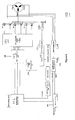
- a 3 phase BLDC motor is driven by 3 half bridges. These enable the phases to be driven by a desired voltage profile at a desired PWM duty cycle.
- the application of a driving profile to the half bridges is controlled by six driving transistors operable in response to a PWM modulation module 101 to apply the driving profile at a desired PWM duty cycle.
- the driving profile is generated by a driving voltage generation unit 103 and its amplitude and duration are controlled by a signal conditioning unit 102.
- the DC-link current flowing through a common shunt resistor Rshunt is measured by a current sampling unit 104.
- the current sampling unit 104 comprises a sample and hold circuit and an analogue to digital converter (ADC) for the digitisation of current samples.
- ADC analogue to digital converter
- the timing of the sample and hold circuit is controlled by a synchronization unit 106.
- the current sample values are stored in a memory 105 before further processing.
- the three BLDC motor phases are also connected to a back EMF sampling unit 107.
- the back EMF sampling unit 107 is operable to measure the voltage of a motor phase while it is undriven in order to determine the back EMF zero crossing point. This thereby enables the rotor position and speed to be estimated.
- the back EMF sampling unit 107 operates in response to the synchronisation unit 106 and selects the appropriate motor phase in response to the synchronisation unit 106.
- a position and speed estimation unit 108 is connected to the back EMF sampling unit 107 for the purpose of estimating the rotor speed and position from the samples taken by the back EMF sampling unit 107.
- the position and speed estimation can be achieved by any suitable means. In one example this may be the well known method of detecting the back EMF zero crossing with a comparator. Alternatively, this may be by way of interpolation from the back EMF sampling unit 107 samples.
- a current processing unit 109 is provided to retrieve current samples stored in the current sampling unit 104 memory and calculate an error function value from the selected current samples.
- the calculated error function value is used by a lead angle control unit 110 to determine the phase angle between the back EMF and the phase current. This can then be input to the driving voltage generation unit 103 to adjust the generated voltage profile.
- FIG. 3 the phase current and back EMF voltage of one phase of the motor is shown.
- phase voltage is periodically undriven for short periods of time. At these times, the phase current is substantially zero. These undriven periods can be implemented, when a zero crossing of the phase current or the back EMF is predicted. The undriven periods are initiated and controlled by the signal conditioning unit 102.
- a time T1 is calculated by the position and speed estimation unit 108.
- the time T1 is representative of the desired absolute maximum value of the phase current.
- figure 4 is an expanded view of part of figure 3 , showing two BEMF zero crossings at T0 and at T2. Whilst figure 4 only shows one phase voltage zero crossings, the skilled man will appreciate that without any deviation from the spirit of the invention zero crossings of the other phases may be used in order to calculate time T1.
- the timing of current samples taken by the current sampling unit 104 is determined by reference to T1.
- the selected current samples CS[1] to CS[10] are symmetrically centred around T1.
- the values of the samples COS[1] to CS[10] are then input into the error function to calculate an error function value.
- the error function is based upon the difference between two sums of current samples: a sum of the selected current samples prior to T1; and a sum of the selected current samples after T1.
- Sum_prior CS 1 + CS 2 + CS 3 + CS 4 + CS 5
- Sum_after CS 6 + CS 7 + CS 8 + CS 9 + CS 10
- Error Function CONSTANT * Sum_prior - Sum_after
- error function implementations are conceivable and are within the spirit of the present invention.
- One such example would be an error function that involves finding the current sample with the maximum value from the (possibly low pass filtered) selected samples CS1...CS10. The time corresponding to the maximum value sample can then be defined as CSmax_time and the error function value can be related to the expression (CSmax_time - T1).
- This alternative function is however less than ideal, because of the big susceptibility to noise present in the current samples and due to the need for a maximum search algorithm.
- the error function can be evaluated after each BEMF zero crossing.
- the lead angle control unit 110 contains a PI controller which calculates a value for lead_angle.
- the value of lead_angle is calculated to be the adjustment in phase angle of the driving voltage profile that will minimise the absolute value of the error function.
- the driving voltage generation unit 103 takes into account both lead_angle and the output of the position and speed estimation unit 108.
- the estimated motor speed may be used additionally in an outer speed control loop involving speed controller 111 to adjust the amplitude (AMP) of the effective driving voltage.
- the driving voltage generation unit 103 selects the three target PWM duty cycle values PWMA_INST, PWMB_INST, PWMC_INST for the respective motor phases A, B, C from a stored driving voltage profile table (typically a sinusoidal profile).
- a stored driving voltage profile table typically a sinusoidal profile.
- PWMC_INST Table_Data ⁇ position + lead_angle + 240 degrees
- the three instantaneous PWM duty cycle values are then input to the signal conditioning unit 102.
- the signal conditioning unit 102 multiplies the three incoming PWMA_INST, PWMB_INST, PWMC_INST values by the speed controller output AMP. Subsequently, the signal conditioning unit 102 performs a suitable signal conditioning depending on the desired state of operation.
Landscapes
- Engineering & Computer Science (AREA)
- Power Engineering (AREA)
- Control Of Motors That Do Not Use Commutators (AREA)
Abstract
Description
- The present invention relates to the control of BLDC motors and in particular to the control of sinusoidally driven BLDC motors.
- Driving BLDC motors with sinusoidal currents improves efficiency of operation and reduces acoustic noise when compared with 120° block mode commutation. As with all schemes for driving BLDC motors, efficient implementation requires that the rotor position and the difference between the applied voltage and the resulting current are monitored such that sinusoidal currents may be applied in phase with the rotor rotation. Present methods for monitoring motor position in sinusoidally driven BLDC motors add significantly to the overall system complexity and cost.
- An example of the above is the monitoring scheme disclosed in the Microchip Technology Inc. Application Note AN1078; "Sensorless Field Oriented Control of PMSM Motors". This discloses a sensorless field oriented control (FOC) method of monitoring the rotor position. This method, for a 3 phase motor, uses at least 2 shunt resistors to measure the phase currents in two of the motor phases and then calculates the third current. The phase currents are then converted to a two axis vector system, which is rotated through a calculated transformation angle (based on a previous iteration of the control loop). The rotation generates two new current variables from which a corresponding pair of voltage variables is generated. A new transformation angle is estimated, and the voltage variables are rotated back to a stationary reference frame and converted to 3 phase voltage values. The 3 phase voltage values can then be used to calculate suitable driving voltages. As the FOC algorithm is very complex mathematically, this method requires a very high calculation power DSP (digital signal processor). Additionally, this method requires at least 2 shunt resistors to measure the motor phase currents needed as input for the FOC algorithm. Both add to the cost and complexity involved with implementing such a system.
- The document
US7294982 discloses measurement of the current zero crossing points during steady state (constant speed, constant load) operation to control a sinusoidally driven BLDC motor. As this method is not reliable during speed or load changes or during driving in PWM mode, a second control scheme is utilised. This involves interrupting the driving current to measure the BEMF and controlling the driving voltage so that a measured motor drive current coincides with calculated current instruction signal. To achieve this, target current values (SPN CRNT DATA) are calculated and subsequently processed in a current error detector, a current control filter and a profile generator module. Calculating target current values in addition to PWM driving voltages at least doubles the computational complexity of the algorithm with respect to calculating PWM driving voltages only. The algorithm therefore also requires expensive hardware such as a DSP for implementation. - The document
US7525268 discloses a method of measuring the current zero crossing for deducing the distance between the time instant of the expected zero crossing and the actual zero crossing instant; the further means is suitable for determining the phase shift between the driving voltage of the electric motor and the induced back electromotive force based on the distance. Typically it is desired that the BEMF zero crossing is aligned with the current zero crossing for optimum motor efficiency. Therefore this method can not be used together with the method of estimating the rotor position based on back EMF zero crossings. - It is therefore an object of the present invention to provide a method of controlling a sinusoidally driven BLDC motor that at least partially overcomes or alleviates the above drawbacks. It is a further object that this might be achieved by directly taking measurements of the back EMF voltage and current samples of all motor phases individually in order to align the phase current with the back EMF voltage.
- According to a first aspect of the present invention there is provided a method of controlling a sinusoidally driven BLDC motor comprising the steps of: determining a time T1 at which a phase current maximum in a particular motor phase should occur based on detected or estimated back EMF zero crossing events; taking a series of samples representative of the phase current of the motor phase at symmetrical intervals before and after the time T1; using the samples to determine an error function value indicative of the lead angle of the phase current; and adjusting the driving voltage profile to minimise or otherwise selecting the absolute magnitude of the error function value.
- Using the above methods, control of a sinusoidally driven BLDC motor can be achieved without the need for position sensors and with just a single shunt resistor in an efficient way. The method is furthermore robust under changing load and/or supply conditions. Additionally, the method has a sufficiently low computational complexity that it is suitable for implementation on a microcontroller.
- The motor driving voltage profile may be a profile substantially proportional to a temporarily-constant voltage profile. The temporarily-constant voltage profile may be selected to be suitable for the particular motor and its particular operation point.
- Samples representative of the phase current of the motor phase may be obtained by taking samples of the DC-link current on a shunt resistor. The current sampling may be undertaken by a current sampling unit comprising a sample and hold circuit connected to an analogue to digital converter. The current sampling operation may be controlled by a synchronisation unit.
- The back EMF zero crossing events may be detected by monitoring the back EMF voltage on the phase for zero crossings. This can be achieved by interpolation from one or more samples of the back EMF or by use of a comparator. Back EMF monitoring can be carried out by a back EMF sampling unit which may comprise a comparator or a sampling unit and interpolation unit. If a back EMF sampling unit is used, it may operate in response to the synchronisation unit.
- Back EMF zero crossing detection may be used to estimate a rotor speed and/or position. The detected back EMF, rotor speed or rotor position may be used to estimate future back EMF zero crossing events or to determine the time T1. In order to implement the above, the back EMF sampling unit may further comprise or be connected to a speed and position estimation unit. The speed and position estimation unit may be operable to determine rotor position and speed based on back EMF zero crossing events. The speed and position estimation unit may be also operable to estimate future back EMF zero crossing events or determine the time T1.
- The error function may be any suitable function. In one preferred embodiment, the error function comprises taking the difference in the sum of the current sample values taken prior to T1 and the sum of all the current sample values taken after T1. In another embodiment, the error function comprises the steps of: determining the maximum current sample value, determining the time at which the maximum current sample was taken and calculating the interval between T1 and the time at which the maximum current sample value was taken. In either instance, the error function value is indicative of the lead angle of the phase current relative to the back EMF.
- The calculation of the error function value may be carried out by a current processing unit. The current processing unit may be operable to receive the output of the current sampling unit and calculate the error function value from the received current sample values. The calculation of the error function may take place after each zero crossing or after selected zero crossings. The selected zero crossings may be selected periodically after n intervals or after a predetermined time interval. Additionally or alternatively, the selected zero crossings may be selected in response to a variation in motor speed or motor load.
- The lead angle may be calculated from the error function value. This calculation may be undertaken by a lead angle control unit. The lead angle control unit may comprise a PI controller (proportional-integral controller). A desired lead_angle value may be calculated which would minimise (or select another desired value of) the error function value. The lead angle control unit may be further operable to calculate the desired lead_angle value.
- The driving voltage profile may be adjusted in response to the lead angle or the desired lead_angle value. The adjustment may comprise advancing or delaying the driving voltage profile. In order to achieve the above, the lead angle control unit may feed the desired lead_angle value into a driving voltage generation unit. The driving voltage generation unit may then be operable to adjust the driving voltage profile in response to the lead angle.
- The driving voltage profiles may be implemented as PWM driving profiles. This may be implemented by the driving voltage generation unit. The driving voltage profiles may be temporarily suspended during a sampling period. A signal conditioning unit may be provided to synchronise the output of the driving voltage generation unit with the motor speed. The signal conditioning unit may be additionally operable to temporarily suspend the driving of one or more phases during a sampling period. The suspension may be undertaken in response to the synchronisation unit
- According to a second aspect of the present invention there is provided a method of monitoring the rotor position in a sinusoidally driven BLDC motor comprising the steps of: determining a time T1 at which a phase current maximum in a particular motor phase should occur based on detected or estimated back EMF zero crossing events; taking a series of samples representative of the phase current of the motor phase at symmetrical intervals before and after the time T1; and using the samples to determine an estimate of rotor position.
- The method of the second aspect of the present invention may incorporate any or all features of the first aspect of the present invention as are desired or as are appropriate.
- Using the above methods, the rotor position of a sinusoidally driven BLDC motor can be calculated without the need for position sensors and with just a single shunt resistor in an efficient way. The method is furthermore robust under changing load and/or supply conditions. Additionally, the method has a sufficiently low computational complexity that it is suitable for implementation on a microcontroller.
- The estimate of rotor position may involve determining an indication of the lead angle of the phase current relative to the back EMF. This indication may be determined by calculating an error function value. The method may then involve the further step of adjusting the driving voltage profile to minimise or otherwise selecting the absolute magnitude of the error function value. By minimising the error function value the phase current may be substantially aligned with the back EMF. This is likely to be the primary mode of operation as this maximises the efficiency of motor operation. By selecting an alternative value, the phase current may be controllably arranged to lag or lead the back EMF by a desired phase angle. This can be useful in field weakening operation of the motor.
- According to a third aspect of the present invention there is provided a BLDC motor operable in accordance with the method of the first aspect of the present invention or the second aspect of the present invention.
- The motor of the third aspect of the present invention may incorporate any or all features of the first or second aspects of the present invention as are desired or as are appropriate.
- The skilled man will appreciate that the above methods may equally be applied to a Permanent Magnet Synchronous Motor (PMSM).
- According to a fourth aspect of the present invention there is provided a method of monitoring the rotor position in a PMSM comprising the steps of: determining a time T1 at which a phase current maximum in a particular motor phase should occur based on detected or estimated back EMF zero crossing events; taking a series of samples representative of the phase current of the motor phase at symmetrical intervals before and after the time T1; and using the samples to determine an estimate of rotor position
- According to a fifth aspect of the present invention there is provided a method of controlling a PMSM comprising the steps of: determining a time T1 at which a phase current maximum in a particular motor phase should occur based on detected or estimated back EMF zero crossing events; taking a series of samples representative of the phase current of the motor phase at symmetrical intervals before and after the time T1; using the samples to determine an error function value indicative of the lead angle of the phase current; and adjusting the driving voltage profile to minimise or otherwise selecting the absolute magnitude of the error function value.
- According to a sixth aspect of the present invention there is provided a PMSM operable in accordance with the method of the fourth aspect of the present invention or the fifth aspect of the present invention.
- The methods of the fourth and fifth aspects of the present invention or the motor of the sixth aspect of the present invention may incorporate any or all features of the first, second and third aspects of the present invention as are desired or as are appropriate.
- In order that the invention is more clearly understood one embodiment will now be described in more detail, by way of example only and with reference to the accompanying drawings, in which:-
- Figure 1A
- illustrates the phase current and back EMF in an undriven coil of a BLDC motor in the event that the back EMF lags the phase current;
- Figure 1B
- illustrates the phase current and back EMF in an undriven coil of a BLDC motor in the event that the back EMF is synchronised with the phase current;
- Figure 1C
- illustrates the phase current and back EMF in an undriven coil of a BLDC motor in the event that the back EMF leads the phase current;
- Figure 2
- shows a block diagram of a BLDC motor of the present invention;
- Figure 3
- shows the phase current and phase voltage of a running BLDC motor according to the present invention; and
- Figure 4
- is an expanded view of
figure 3 illustrating the times at which samples of the phase current are taken according to the present invention. - Turning now to
figure 1 , the relationship between the back EMF voltage and the phase current of a phase A of a BLDC motor is shown. In the case of a 3 phase BLDC motor there will be two further phases B, C each having a like back EMF and current relationship. In the example offigure 1A the back EMF lags the phase current; infigure 1B the back EMF is synchronised with the phase current; and infigure 1C the back EMF leads the phase current. - Since maximum operational efficiency (and minimised acoustic noise) occurs when the back EMF and phase current are synchronised (
figure 1B ) the present invention will be described in terms of achieving such a situation. The skilled man will however appreciate that the present invention may also be utilised to arrange for the back EMF to lag or lead the phase current by a desired amount. This may be desirable in certain situations such as in field weakening operation. - Turning now to
figure 2 , a 3 phase BLDC motor is driven by 3 half bridges. These enable the phases to be driven by a desired voltage profile at a desired PWM duty cycle. The application of a driving profile to the half bridges is controlled by six driving transistors operable in response to aPWM modulation module 101 to apply the driving profile at a desired PWM duty cycle. The driving profile is generated by a drivingvoltage generation unit 103 and its amplitude and duration are controlled by asignal conditioning unit 102. - In the present invention, the DC-link current flowing through a common shunt resistor Rshunt is measured by a
current sampling unit 104. Thecurrent sampling unit 104 comprises a sample and hold circuit and an analogue to digital converter (ADC) for the digitisation of current samples. The timing of the sample and hold circuit is controlled by asynchronization unit 106. The current sample values are stored in a memory 105 before further processing. - The three BLDC motor phases are also connected to a back
EMF sampling unit 107. The backEMF sampling unit 107 is operable to measure the voltage of a motor phase while it is undriven in order to determine the back EMF zero crossing point. This thereby enables the rotor position and speed to be estimated. The backEMF sampling unit 107 operates in response to thesynchronisation unit 106 and selects the appropriate motor phase in response to thesynchronisation unit 106. - A position and speed estimation unit 108 is connected to the back
EMF sampling unit 107 for the purpose of estimating the rotor speed and position from the samples taken by the backEMF sampling unit 107. The position and speed estimation can be achieved by any suitable means. In one example this may be the well known method of detecting the back EMF zero crossing with a comparator. Alternatively, this may be by way of interpolation from the backEMF sampling unit 107 samples. - A current processing unit 109 is provided to retrieve current samples stored in the
current sampling unit 104 memory and calculate an error function value from the selected current samples. The calculated error function value is used by a leadangle control unit 110 to determine the phase angle between the back EMF and the phase current. This can then be input to the drivingvoltage generation unit 103 to adjust the generated voltage profile. - Turning now to
figures 3 &4 , the specific selection of samples and error function calculation are explained in greater detail. Infigure 3 the phase current and back EMF voltage of one phase of the motor is shown. - In order to allow the measurement of the back EMF the phase voltage is periodically undriven for short periods of time. At these times, the phase current is substantially zero. These undriven periods can be implemented, when a zero crossing of the phase current or the back EMF is predicted. The undriven periods are initiated and controlled by the
signal conditioning unit 102. - In response to the determination or estimation of a back EMF zero crossing event for the phase, a time T1 is calculated by the position and speed estimation unit 108. The time T1 is representative of the desired absolute maximum value of the phase current. Typically, T1 is the midpoint between a detected back EMF zero crossing event and the next predicted back EMF zero crossing event, determined in relation to the time of the last detected or estimated back EMF zero crossing event and the rotor speed. If a phase angle between the current and the back EMF is desired T1 may be offset from this midpoint; if synchronisation is desired, then the offset may be set to zero. In essence:-

- This is graphically illustrated by
figure 4 which is an expanded view of part offigure 3 , showing two BEMF zero crossings at T0 and at T2. Whilstfigure 4 only shows one phase voltage zero crossings, the skilled man will appreciate that without any deviation from the spirit of the invention zero crossings of the other phases may be used in order to calculate time T1. - The timing of current samples taken by the
current sampling unit 104 is determined by reference to T1. The selected current samples CS[1] to CS[10] are symmetrically centred around T1. The values of the samples COS[1] to CS[10] are then input into the error function to calculate an error function value. - In one suitable implementation the error function is based upon the difference between two sums of current samples: a sum of the selected current samples prior to T1; and a sum of the selected current samples after T1. In the example of
figure 4 :


- In alternative embodiments, other error function implementations are conceivable and are within the spirit of the present invention. One such example would be an error function that involves finding the current sample with the maximum value from the (possibly low pass filtered) selected samples CS1...CS10. The time corresponding to the maximum value sample can then be defined as CSmax_time and the error function value can be related to the expression (CSmax_time - T1). This alternative function is however less than ideal, because of the big susceptibility to noise present in the current samples and due to the need for a maximum search algorithm.
- In the preferred embodiment, the error function can be evaluated after each BEMF zero crossing.
- As above, the calculated error function value is input to the lead
angle control unit 110. The leadangle control unit 110 contains a PI controller which calculates a value for lead_angle. The value of lead_angle is calculated to be the adjustment in phase angle of the driving voltage profile that will minimise the absolute value of the error function. - In generating and adjusting the driving voltage profile the driving
voltage generation unit 103 takes into account both lead_angle and the output of the position and speed estimation unit 108. The estimated motor speed may be used additionally in an outer speed control loop involving speed controller 111 to adjust the amplitude (AMP) of the effective driving voltage. - Taking into account the speed and position data the driving
voltage generation unit 103 selects the three target PWM duty cycle values PWMA_INST, PWMB_INST, PWMC_INST for the respective motor phases A, B, C from a stored driving voltage profile table (typically a sinusoidal profile). The adjustment of each profile in response to lead_angle takes the following form:


- The three instantaneous PWM duty cycle values are then input to the
signal conditioning unit 102. Thesignal conditioning unit 102 multiplies the three incoming PWMA_INST, PWMB_INST, PWMC_INST values by the speed controller output AMP. Subsequently, thesignal conditioning unit 102 performs a suitable signal conditioning depending on the desired state of operation. - It is of course to be understood that the invention is not to be restricted to the details of the above embodiment which is described by way of example only.
Claims (17)
- A method of controlling a sinusoidally driven brushless DC (BLDC) motor or a sinusoidally driven Permanent Magnet Synchronous Motor (PMSM), the method comprising the steps of: determining a time T1 at which a phase current maximum in a particular motor phase should occur based on detected or estimated back EMF zero crossing events; taking a series of samples representative of the phase current of the motor phase at symmetrical intervals before and after the time T1; using the samples to determine an error function value indicative of the lead angle of the phase current; and adjusting the driving voltage profile to minimise or otherwise selecting the absolute magnitude of the error function value.
- A method as claimed in claim 1 wherein the motor driving voltage profile is a profile substantially proportional to a temporarily-constant voltage profile.
- A method as claimed in claim 1 or claim 2 wherein samples representative of the phase current of the motor phase are obtained by taking samples of the DC-link current on a shunt resistor.
- A method as claimed in any one of claims 1 to 3 wherein the back EMF zero crossing events are detected by monitoring the back EMF voltage on the phase for zero crossings.
- A method as claimed in claim 4 wherein the detected back EMF is used to estimate a rotor speed and/or position.
- A method as claimed in claim 4 or claim 5 wherein the detected back EMF, rotor speed or rotor position is used to estimate future back EMF zero crossing events or to determine the time T1.
- A method as claimed in any one of claims 1 to 6 wherein the error function comprises taking the difference in the sum of the current sample values taken prior to T1 and the sum of all the current sample values taken after T1.
- A method as claimed in any one of claims 1 to 6 wherein the error function comprises the steps of: determining the maximum current sample value, determining the time at which the maximum current sample was taken and calculating the interval between T1 and the time at which the maximum current sample value was taken.
- A method as claimed in any one of claims 1 to 8 wherein the lead angle is calculated from the error function value.
- A method as claimed in claim 9 wherein a desired lead_angle value is calculated which would minimise (or select another desired value of) the error function value.
- A method as claimed in claim 10 wherein the driving voltage profile is adjusted in response to the lead angle or the desired lead_angle value.
- A method as claimed in any one of claims 1 to 11 wherein the driving voltage profiles are implemented as PWM driving profiles.
- A method as claimed in any one of claims 1 to 12 wherein the driving voltage profiles are temporarily suspended during a sampling period.
- A method of monitoring the rotor position in a sinusoidally driven brushless DC (BLDC) motor or a sinusoidally driven Permanent Magnet Synchronous Motor (PMSM), the method comprising the steps of: determining a time T1 at which a phase current maximum in a particular motor phase should occur based on detected or estimated back EMF zero crossing events; taking a series of samples representative of the phase current of the motor phase at symmetrical intervals before and after the time T1; and using the samples to determine an estimate of rotor position.
- A method as claimed in claim 14 wherein the estimate of rotor position involves determining an indication of the lead angle of the phase current relative to the back EMF by calculating an error function value.
- A method as claimed in claim 15 wherein the method involves the further step of adjusting the driving voltage profile to minimise or otherwise select the absolute magnitude of the error function value.
- A brushless DC (BLDC) motor or a Permanent Magnet Synchronous Motor (PMSM) operable in accordance with the method of any preceding claim.
Applications Claiming Priority (1)
| Application Number | Priority Date | Filing Date | Title |
|---|---|---|---|
| GBGB0916543.2A GB0916543D0 (en) | 2009-09-21 | 2009-09-21 | Control of sinusoidally driven brushless dc (bldc) motors |
Publications (3)
| Publication Number | Publication Date |
|---|---|
| EP2302785A2 true EP2302785A2 (en) | 2011-03-30 |
| EP2302785A3 EP2302785A3 (en) | 2013-07-31 |
| EP2302785B1 EP2302785B1 (en) | 2015-02-18 |
Family
ID=41278059
Family Applications (1)
| Application Number | Title | Priority Date | Filing Date |
|---|---|---|---|
| EP10177979.1A Active EP2302785B1 (en) | 2009-09-21 | 2010-09-21 | Control of sinusoidally driven brushless DC (BLDC) motors |
Country Status (3)
| Country | Link |
|---|---|
| US (1) | US8461789B2 (en) |
| EP (1) | EP2302785B1 (en) |
| GB (1) | GB0916543D0 (en) |
Cited By (8)
| Publication number | Priority date | Publication date | Assignee | Title |
|---|---|---|---|---|
| WO2014199141A1 (en) * | 2013-06-13 | 2014-12-18 | Dyson Technology Limited | Method of controlling of a brushless permanent-magnet motor |
| DE102014107949A1 (en) * | 2014-06-05 | 2015-12-17 | Hella Kgaa Hueck & Co. | Method and device for detecting a zero crossing of a current through a strand of a brushless DC motor |
| DE102014107946A1 (en) * | 2014-06-05 | 2015-12-17 | Hella Kgaa Hueck & Co. | Method for measuring the back EMF in a string of a brushless DC motor |
| US9431938B2 (en) | 2013-06-13 | 2016-08-30 | Dyson Technology Limited | Method of controlling a brushless permanent-magnet motor |
| US9438150B2 (en) | 2013-06-13 | 2016-09-06 | Dyson Technology Limited | Method of controlling a brushless permanent-magnet motor |
| US9438149B2 (en) | 2013-06-13 | 2016-09-06 | Dyson Technology Limited | Method of controlling a brushless permanent-magnet motor |
| EP3736967A1 (en) * | 2019-05-06 | 2020-11-11 | Melexis Technologies NV | Lead angle detection for bldc motor control |
| EP4333290A1 (en) * | 2022-08-31 | 2024-03-06 | LX Semicon Co., Ltd. | Motor driver, motor drive system, and method of driving motor |
Families Citing this family (20)
| Publication number | Priority date | Publication date | Assignee | Title |
|---|---|---|---|---|
| GB0815672D0 (en) * | 2008-08-28 | 2008-10-08 | Melexis Nv | Improvements of accuracy of rotor position detection relating to the control of brushless dc motors |
| US8653773B2 (en) * | 2012-02-02 | 2014-02-18 | Lexmark Internatonal, Inc. | Method for calibrating a drive motor for a toner metering device in an imaging apparatus |
| US8766578B2 (en) | 2012-02-27 | 2014-07-01 | Canadian Space Agency | Method and apparatus for high velocity ripple suppression of brushless DC motors having limited drive/amplifier bandwidth |
| DE102012102868A1 (en) * | 2012-04-02 | 2013-10-02 | Minebea Co., Ltd. | Method for operating a brushless electric motor |
| US9503005B2 (en) * | 2012-08-20 | 2016-11-22 | Canon Kabushiki Kaisha | Control device and stepping motor control method |
| KR102155269B1 (en) * | 2013-09-24 | 2020-09-11 | 한국전자통신연구원 | Motor driving circuit and operating method thereof |
| GB2520538A (en) | 2013-11-25 | 2015-05-27 | Melexis Technologies Nv | Phase current regulation in BLDC motors |
| GB2542633A (en) * | 2015-09-28 | 2017-03-29 | Melexis Technologies Nv | Method of starting a three-phase BLDC motor and motor driver using same |
| US10075107B2 (en) * | 2015-11-03 | 2018-09-11 | Nxp Usa, Inc. | Method and apparatus for motor lock or stall detection |
| US10312847B2 (en) * | 2016-05-09 | 2019-06-04 | Allegro Microsystems, Llc | Motor control using phase current and phase voltage |
| US9991827B1 (en) * | 2017-02-06 | 2018-06-05 | Texas Instruments Incorporated | Methods and apparatus for automatic lead angle adjustment using fly-back voltage for brushless DC control |
| WO2020133113A1 (en) * | 2018-12-27 | 2020-07-02 | 广东美的白色家电技术创新中心有限公司 | Determination method and apparatus for bldc counter-electromotive force zero crossing point threshold, and storage medium |
| US11303235B2 (en) | 2019-04-25 | 2022-04-12 | Black & Decker Inc. | Dual-controller system for a sensorless brushless motor control |
| US20240001801A1 (en) * | 2020-11-18 | 2024-01-04 | Blue Volta Technology Inc. | Powertrain for an electric vehicle featuring a scalable and manageable energy storage system |
| US11916496B2 (en) | 2021-06-30 | 2024-02-27 | Texas Instruments Incorporated | Motor controller and a method for controlling a motor |
| US11764710B2 (en) | 2021-06-30 | 2023-09-19 | Texas Instruments Incorporated | Automatic transition of motor controller from open-loop control to closed-loop control |
| US11728751B2 (en) * | 2021-08-31 | 2023-08-15 | Texas Instruments Incorporated | Resynchronization of brushless DC motors |
| US11777424B2 (en) * | 2021-10-06 | 2023-10-03 | Elite Semiconductor Microelectronics Technology Inc. | Method for determining initial rotor position of permanent magnet synchronous motor according to phase current differences and line current differences and associated motor device |
| EP4187776B1 (en) * | 2021-11-30 | 2024-10-02 | NXP USA, Inc. | Electric motor fault detection |
| EP4064550B1 (en) * | 2022-08-09 | 2024-06-05 | Pfeiffer Vacuum Technology AG | Permanent magnet synchornous machine |
Family Cites Families (52)
| Publication number | Priority date | Publication date | Assignee | Title |
|---|---|---|---|---|
| US4746844A (en) | 1985-07-16 | 1988-05-24 | Maghemite Inc. | Control and operation of brushless continuous torque toroid motor |
| US4772839A (en) | 1987-10-27 | 1988-09-20 | General Electric Company | Rotor position estimator for switched reluctance motor |
| US4928043A (en) | 1988-11-14 | 1990-05-22 | Synektron Corporation | Back EMF sampling circuit for phase locked loop motor control |
| US5001405A (en) | 1989-09-27 | 1991-03-19 | Seagate Technology, Inc. | Position detection for a brushless DC motor |
| US4992710A (en) | 1989-09-27 | 1991-02-12 | Seagate Technology, Inc. | Position detection for a brushless DC motor with sample time optimization |
| AU630820B2 (en) | 1990-07-04 | 1992-11-05 | Matsushita Electric Industrial Co., Ltd. | Brushless dc motor |
| US5097190A (en) | 1991-02-11 | 1992-03-17 | General Electric Company | Rotor position estimator for a switched reluctance machine |
| WO1992019038A1 (en) | 1991-04-11 | 1992-10-29 | Elin Energieanwendung Gesellschaft M.B.H. | Process and circuits for determining machine-related electromagnetic and mechanical state variables on electrodynamic induction machines supplied via converters |
| US5134349A (en) | 1991-05-28 | 1992-07-28 | Kruse David L | Two-phase brushless dc motor controller |
| US5191270A (en) | 1991-06-07 | 1993-03-02 | Sgs-Thomson Microelectronics, Inc. | Method for starting a motor |
| US5517095A (en) | 1991-10-03 | 1996-05-14 | Sgs-Thomson Microelectronics, Inc. | Method and apparatus for operating polyphase DC motors using a PWM chopping signal in zero crossing determination |
| US5191269A (en) | 1991-10-10 | 1993-03-02 | Sgs-Thomson Microelectronics, Inc. | Brushless direct current motor with minimized current ripple and method |
| US5384527A (en) * | 1993-05-12 | 1995-01-24 | Sundstrand Corporation | Rotor position detector with back EMF voltage estimation |
| US5446359A (en) | 1993-12-29 | 1995-08-29 | Emerson Electric Co. | Current decay control in switched reluctance motor |
| US5473240A (en) * | 1993-12-30 | 1995-12-05 | Whirlpool Corporation | Motor control using third harmonic stator voltage signal |
| US5525874A (en) | 1995-01-30 | 1996-06-11 | Delco Electronics Corp. | Digital slope compensation in a current controller |
| WO1997027667A1 (en) | 1996-01-24 | 1997-07-31 | Philips Electronics N.V. | Arrangement for supplying drive signals to a plurality of windings of a multi-phase d.c. motor, drive system and disk drive |
| FR2747521B1 (en) | 1996-04-12 | 1998-06-26 | Sgs Thomson Microelectronics | CONTROL OF A MOTOR WITHOUT MANIFOLD |
| US6163120A (en) | 1996-12-17 | 2000-12-19 | Stmicroelectronics, Inc. | Simple back emf reconstruction in pulse width modulation (PWM) mode |
| JP3440274B2 (en) * | 1997-02-05 | 2003-08-25 | フイッシャー アンド ペイケル アプライアンシーズ リミテッド | Brushless DC motor control |
| EP0892489B1 (en) | 1997-07-15 | 2005-10-05 | STMicroelectronics S.r.l. | Detection of instantaneous position of the rotor of a brushless DC motor driven in a tripolar mode |
| US6107772A (en) | 1997-09-26 | 2000-08-22 | Dana Corporation | Sensorless switched reluctance motor control |
| US6072289A (en) | 1998-04-28 | 2000-06-06 | Texas Instruments Incorporated | System and method for controlling high side slew rate in a spindle motor driver |
| JPH11318097A (en) * | 1998-04-30 | 1999-11-16 | Toshiba Corp | Drive control device for brushless motor |
| US20010048278A1 (en) | 1999-02-04 | 2001-12-06 | Glen C. Young | Cross coupled motor gate drive |
| US6081091A (en) * | 1999-03-08 | 2000-06-27 | Motorola, Inc. | Motor controller, integrated circuit, and method of controlling a motor |
| JP2000278987A (en) * | 1999-03-19 | 2000-10-06 | Toshiba Corp | Inverter device |
| US6124689A (en) | 1999-03-26 | 2000-09-26 | Quantum Corporation | Trapezoidal spindle motor driver |
| US6011368A (en) | 1999-03-30 | 2000-01-04 | Dana Corporation | Sensorless detection of a locked rotor in a switched reluctance motor |
| US6023141A (en) | 1999-05-13 | 2000-02-08 | Motorola, Inc. | Method and apparatus for electronically commutating an electric motor |
| US7138776B1 (en) | 1999-07-08 | 2006-11-21 | Heartware, Inc. | Method and apparatus for controlling brushless DC motors in implantable medical devices |
| JP3411878B2 (en) * | 2000-03-06 | 2003-06-03 | 株式会社日立製作所 | Method for estimating rotor position of synchronous motor, control method without position sensor, and control device |
| US6462495B1 (en) | 2000-04-25 | 2002-10-08 | Infineon Technologies Ag | Controlling a brushless DC motor |
| JP3979561B2 (en) | 2000-08-30 | 2007-09-19 | 株式会社日立製作所 | AC motor drive system |
| EP1198059A3 (en) | 2000-10-11 | 2004-03-17 | Matsushita Electric Industrial Co., Ltd. | Method and apparatus for position-sensorless motor control |
| US6795268B1 (en) | 2000-10-31 | 2004-09-21 | Western Digital Technologies, Inc. | Disk drive employing seek time vcm ir voltage calibration for velocity control of an actuator arm |
| DE10162380A1 (en) | 2001-12-19 | 2003-07-03 | Bosch Gmbh Robert | Procedure for starting a brushless DC motor |
| ITMI20012835A1 (en) | 2001-12-28 | 2003-06-28 | Abb Service Srl | PROCEDURE FOR DETERMINING THE ROTOR POSITION OF A SYNCHRONOUS ALTERNATING CURRENT MACHINE WITH PERMANENT MAGNETS |
| DE10229319A1 (en) | 2002-06-29 | 2004-01-29 | Braun Gmbh | Method for controlling an oscillating electric motor of a small electrical appliance |
| US6828753B2 (en) | 2002-08-26 | 2004-12-07 | International Rectifier Corporation | Input filter for A.C. motor phase current sensing |
| JP3693173B2 (en) | 2002-10-16 | 2005-09-07 | 日本サーボ株式会社 | Single phase brushless DC motor |
| JP2004343862A (en) | 2003-05-14 | 2004-12-02 | Matsushita Electric Ind Co Ltd | Motor control device |
| CN100364225C (en) | 2003-06-30 | 2008-01-23 | 松下电器产业株式会社 | Sensorless motor driving device and driving method thereof |
| US6995530B2 (en) | 2004-04-22 | 2006-02-07 | International Business Machines Corporation | System, method, and an article of manufacture for starting a brushless direct current motor |
| ITTO20040399A1 (en) | 2004-06-16 | 2004-09-16 | Univ Catania | CONTROL SYSTEM AND METHOD FOR ELECTRIC DRIVES WITH AC MOTORS. |
| JP4513536B2 (en) | 2004-12-06 | 2010-07-28 | 株式会社豊田自動織機 | Inverter device |
| US7166980B1 (en) | 2005-02-23 | 2007-01-23 | Legrand Richard Mark | Methods and apparatus for monitoring a brushed permanent magnet motor using back-emf measurements |
| US7141949B2 (en) | 2005-03-07 | 2006-11-28 | Fisher & Paykel Appliances Limited | Low noise back EMF sensing brushless DC motor |
| JP4425193B2 (en) | 2005-08-16 | 2010-03-03 | 三洋電機株式会社 | Motor position sensorless control device |
| JP4665735B2 (en) * | 2005-11-30 | 2011-04-06 | 株式会社日立製作所 | Synchronous motor drive system and synchronous motor drive method |
| US8030867B1 (en) | 2006-07-29 | 2011-10-04 | Ixys Ch Gmbh | Sample and hold time stamp for sensing zero crossing of back electromotive force in 3-phase brushless DC motors |
| JP4492732B2 (en) * | 2008-05-13 | 2010-06-30 | 株式会社デンソー | Motor drive device and drive device state determination method |
-
2009
- 2009-09-21 GB GBGB0916543.2A patent/GB0916543D0/en not_active Ceased
-
2010
- 2010-09-21 EP EP10177979.1A patent/EP2302785B1/en active Active
- 2010-09-21 US US12/887,410 patent/US8461789B2/en active Active
Cited By (12)
| Publication number | Priority date | Publication date | Assignee | Title |
|---|---|---|---|---|
| WO2014199141A1 (en) * | 2013-06-13 | 2014-12-18 | Dyson Technology Limited | Method of controlling of a brushless permanent-magnet motor |
| CN105474530A (en) * | 2013-06-13 | 2016-04-06 | 戴森技术有限公司 | Method of controlling brushless permanent-magnet motor |
| US9431938B2 (en) | 2013-06-13 | 2016-08-30 | Dyson Technology Limited | Method of controlling a brushless permanent-magnet motor |
| US9438150B2 (en) | 2013-06-13 | 2016-09-06 | Dyson Technology Limited | Method of controlling a brushless permanent-magnet motor |
| US9438149B2 (en) | 2013-06-13 | 2016-09-06 | Dyson Technology Limited | Method of controlling a brushless permanent-magnet motor |
| DE102014107949A1 (en) * | 2014-06-05 | 2015-12-17 | Hella Kgaa Hueck & Co. | Method and device for detecting a zero crossing of a current through a strand of a brushless DC motor |
| DE102014107946A1 (en) * | 2014-06-05 | 2015-12-17 | Hella Kgaa Hueck & Co. | Method for measuring the back EMF in a string of a brushless DC motor |
| EP3736967A1 (en) * | 2019-05-06 | 2020-11-11 | Melexis Technologies NV | Lead angle detection for bldc motor control |
| CN111987939A (en) * | 2019-05-06 | 2020-11-24 | 迈来芯科技有限公司 | Lead angle detection for BLDC motor control |
| US11165380B2 (en) | 2019-05-06 | 2021-11-02 | Melexis Technologies Nv | Lead angle detection for BLDC motor control |
| EP4333290A1 (en) * | 2022-08-31 | 2024-03-06 | LX Semicon Co., Ltd. | Motor driver, motor drive system, and method of driving motor |
| US12301155B2 (en) | 2022-08-31 | 2025-05-13 | Lx Semicon Co., Ltd. | Motor driver, motor drive system, and method of driving motor |
Also Published As
| Publication number | Publication date |
|---|---|
| US8461789B2 (en) | 2013-06-11 |
| EP2302785A3 (en) | 2013-07-31 |
| EP2302785B1 (en) | 2015-02-18 |
| GB0916543D0 (en) | 2009-10-28 |
| US20110074327A1 (en) | 2011-03-31 |
Similar Documents
| Publication | Publication Date | Title |
|---|---|---|
| EP2302785B1 (en) | Control of sinusoidally driven brushless DC (BLDC) motors | |
| US8461796B2 (en) | Motor drive circuit for driving a synchronous motor | |
| EP2719071B1 (en) | Electric drive unit | |
| JP7289926B2 (en) | How to Determine the Rotor Position of a Brushless Permanent Magnet Motor | |
| EP2704307B1 (en) | Brushless motor control device and brushless motor control method | |
| EP2053734B1 (en) | Motor control apparatus and motor system | |
| CN116868500A (en) | Methods of controlling brushless permanent magnet motors | |
| JP5130876B2 (en) | V / f control device for permanent magnet synchronous motor | |
| KR101448677B1 (en) | Apparatus and method for estimating rotor position of brushless dc motor | |
| KR20160065291A (en) | Motor driving module | |
| EP3557759B1 (en) | Motor controlling apparatus and method of the same | |
| JP2011078222A (en) | Motor drive control circuit | |
| JP4051833B2 (en) | Vector controller for permanent magnet synchronous motor | |
| CN107852113B (en) | Power conversion device and control method of power conversion device | |
| JP5406011B2 (en) | Motor drive circuit | |
| JP2012186911A (en) | Motor control device | |
| JP6102768B2 (en) | Motor control device | |
| JP6156162B2 (en) | Motor control device | |
| EP0994561A2 (en) | Method for restarting a synchronous permanent magnet motor still rotating | |
| JP6116449B2 (en) | Electric motor drive control device | |
| JP4127000B2 (en) | Motor control device | |
| EP1806835B1 (en) | Motor driving apparatus | |
| CN111987939A (en) | Lead angle detection for BLDC motor control | |
| JP2004208385A (en) | Method and apparatus for controlling motor | |
| JP4123877B2 (en) | Motor control device |
Legal Events
| Date | Code | Title | Description |
|---|---|---|---|
| PUAI | Public reference made under article 153(3) epc to a published international application that has entered the european phase |
Free format text: ORIGINAL CODE: 0009012 |
|
| AK | Designated contracting states |
Kind code of ref document: A2 Designated state(s): AL AT BE BG CH CY CZ DE DK EE ES FI FR GB GR HR HU IE IS IT LI LT LU LV MC MK MT NL NO PL PT RO SE SI SK SM TR |
|
| AX | Request for extension of the european patent |
Extension state: BA ME RS |
|
| PUAL | Search report despatched |
Free format text: ORIGINAL CODE: 0009013 |
|
| AK | Designated contracting states |
Kind code of ref document: A3 Designated state(s): AL AT BE BG CH CY CZ DE DK EE ES FI FR GB GR HR HU IE IS IT LI LT LU LV MC MK MT NL NO PL PT RO SE SI SK SM TR |
|
| AX | Request for extension of the european patent |
Extension state: BA ME RS |
|
| RIC1 | Information provided on ipc code assigned before grant |
Ipc: H02P 25/02 20060101ALI20130624BHEP Ipc: H02P 6/18 20060101AFI20130624BHEP |
|
| RAP1 | Party data changed (applicant data changed or rights of an application transferred) |
Owner name: MELEXIS TECHNOLOGIES NV |
|
| 17P | Request for examination filed |
Effective date: 20140129 |
|
| RBV | Designated contracting states (corrected) |
Designated state(s): AL AT BE BG CH CY CZ DE DK EE ES FI FR GB GR HR HU IE IS IT LI LT LU LV MC MK MT NL NO PL PT RO SE SI SK SM TR |
|
| GRAP | Despatch of communication of intention to grant a patent |
Free format text: ORIGINAL CODE: EPIDOSNIGR1 |
|
| INTG | Intention to grant announced |
Effective date: 20140904 |
|
| GRAS | Grant fee paid |
Free format text: ORIGINAL CODE: EPIDOSNIGR3 |
|
| GRAA | (expected) grant |
Free format text: ORIGINAL CODE: 0009210 |
|
| AK | Designated contracting states |
Kind code of ref document: B1 Designated state(s): AL AT BE BG CH CY CZ DE DK EE ES FI FR GB GR HR HU IE IS IT LI LT LU LV MC MK MT NL NO PL PT RO SE SI SK SM TR |
|
| REG | Reference to a national code |
Ref country code: GB Ref legal event code: FG4D |
|
| REG | Reference to a national code |
Ref country code: CH Ref legal event code: EP |
|
| REG | Reference to a national code |
Ref country code: AT Ref legal event code: REF Ref document number: 711006 Country of ref document: AT Kind code of ref document: T Effective date: 20150315 |
|
| REG | Reference to a national code |
Ref country code: IE Ref legal event code: FG4D |
|
| REG | Reference to a national code |
Ref country code: DE Ref legal event code: R096 Ref document number: 602010022285 Country of ref document: DE Effective date: 20150402 |
|
| REG | Reference to a national code |
Ref country code: NL Ref legal event code: T3 |
|
| REG | Reference to a national code |
Ref country code: AT Ref legal event code: MK05 Ref document number: 711006 Country of ref document: AT Kind code of ref document: T Effective date: 20150218 |
|
| REG | Reference to a national code |
Ref country code: LT Ref legal event code: MG4D |
|
| PG25 | Lapsed in a contracting state [announced via postgrant information from national office to epo] |
Ref country code: SE Free format text: LAPSE BECAUSE OF FAILURE TO SUBMIT A TRANSLATION OF THE DESCRIPTION OR TO PAY THE FEE WITHIN THE PRESCRIBED TIME-LIMIT Effective date: 20150218 Ref country code: FI Free format text: LAPSE BECAUSE OF FAILURE TO SUBMIT A TRANSLATION OF THE DESCRIPTION OR TO PAY THE FEE WITHIN THE PRESCRIBED TIME-LIMIT Effective date: 20150218 Ref country code: LT Free format text: LAPSE BECAUSE OF FAILURE TO SUBMIT A TRANSLATION OF THE DESCRIPTION OR TO PAY THE FEE WITHIN THE PRESCRIBED TIME-LIMIT Effective date: 20150218 Ref country code: HR Free format text: LAPSE BECAUSE OF FAILURE TO SUBMIT A TRANSLATION OF THE DESCRIPTION OR TO PAY THE FEE WITHIN THE PRESCRIBED TIME-LIMIT Effective date: 20150218 Ref country code: NO Free format text: LAPSE BECAUSE OF FAILURE TO SUBMIT A TRANSLATION OF THE DESCRIPTION OR TO PAY THE FEE WITHIN THE PRESCRIBED TIME-LIMIT Effective date: 20150518 Ref country code: ES Free format text: LAPSE BECAUSE OF FAILURE TO SUBMIT A TRANSLATION OF THE DESCRIPTION OR TO PAY THE FEE WITHIN THE PRESCRIBED TIME-LIMIT Effective date: 20150218 |
|
| PG25 | Lapsed in a contracting state [announced via postgrant information from national office to epo] |
Ref country code: GR Free format text: LAPSE BECAUSE OF FAILURE TO SUBMIT A TRANSLATION OF THE DESCRIPTION OR TO PAY THE FEE WITHIN THE PRESCRIBED TIME-LIMIT Effective date: 20150519 Ref country code: IS Free format text: LAPSE BECAUSE OF FAILURE TO SUBMIT A TRANSLATION OF THE DESCRIPTION OR TO PAY THE FEE WITHIN THE PRESCRIBED TIME-LIMIT Effective date: 20150618 Ref country code: LV Free format text: LAPSE BECAUSE OF FAILURE TO SUBMIT A TRANSLATION OF THE DESCRIPTION OR TO PAY THE FEE WITHIN THE PRESCRIBED TIME-LIMIT Effective date: 20150218 Ref country code: AT Free format text: LAPSE BECAUSE OF FAILURE TO SUBMIT A TRANSLATION OF THE DESCRIPTION OR TO PAY THE FEE WITHIN THE PRESCRIBED TIME-LIMIT Effective date: 20150218 |
|
| REG | Reference to a national code |
Ref country code: FR Ref legal event code: PLFP Year of fee payment: 6 |
|
| PG25 | Lapsed in a contracting state [announced via postgrant information from national office to epo] |
Ref country code: SK Free format text: LAPSE BECAUSE OF FAILURE TO SUBMIT A TRANSLATION OF THE DESCRIPTION OR TO PAY THE FEE WITHIN THE PRESCRIBED TIME-LIMIT Effective date: 20150218 Ref country code: CZ Free format text: LAPSE BECAUSE OF FAILURE TO SUBMIT A TRANSLATION OF THE DESCRIPTION OR TO PAY THE FEE WITHIN THE PRESCRIBED TIME-LIMIT Effective date: 20150218 Ref country code: EE Free format text: LAPSE BECAUSE OF FAILURE TO SUBMIT A TRANSLATION OF THE DESCRIPTION OR TO PAY THE FEE WITHIN THE PRESCRIBED TIME-LIMIT Effective date: 20150218 Ref country code: RO Free format text: LAPSE BECAUSE OF FAILURE TO SUBMIT A TRANSLATION OF THE DESCRIPTION OR TO PAY THE FEE WITHIN THE PRESCRIBED TIME-LIMIT Effective date: 20150218 Ref country code: DK Free format text: LAPSE BECAUSE OF FAILURE TO SUBMIT A TRANSLATION OF THE DESCRIPTION OR TO PAY THE FEE WITHIN THE PRESCRIBED TIME-LIMIT Effective date: 20150218 |
|
| REG | Reference to a national code |
Ref country code: DE Ref legal event code: R097 Ref document number: 602010022285 Country of ref document: DE |
|
| PG25 | Lapsed in a contracting state [announced via postgrant information from national office to epo] |
Ref country code: PL Free format text: LAPSE BECAUSE OF FAILURE TO SUBMIT A TRANSLATION OF THE DESCRIPTION OR TO PAY THE FEE WITHIN THE PRESCRIBED TIME-LIMIT Effective date: 20150218 |
|
| PLBE | No opposition filed within time limit |
Free format text: ORIGINAL CODE: 0009261 |
|
| STAA | Information on the status of an ep patent application or granted ep patent |
Free format text: STATUS: NO OPPOSITION FILED WITHIN TIME LIMIT |
|
| PG25 | Lapsed in a contracting state [announced via postgrant information from national office to epo] |
Ref country code: IT Free format text: LAPSE BECAUSE OF FAILURE TO SUBMIT A TRANSLATION OF THE DESCRIPTION OR TO PAY THE FEE WITHIN THE PRESCRIBED TIME-LIMIT Effective date: 20150218 |
|
| 26N | No opposition filed |
Effective date: 20151119 |
|
| PG25 | Lapsed in a contracting state [announced via postgrant information from national office to epo] |
Ref country code: SI Free format text: LAPSE BECAUSE OF FAILURE TO SUBMIT A TRANSLATION OF THE DESCRIPTION OR TO PAY THE FEE WITHIN THE PRESCRIBED TIME-LIMIT Effective date: 20150218 |
|
| PG25 | Lapsed in a contracting state [announced via postgrant information from national office to epo] |
Ref country code: MC Free format text: LAPSE BECAUSE OF FAILURE TO SUBMIT A TRANSLATION OF THE DESCRIPTION OR TO PAY THE FEE WITHIN THE PRESCRIBED TIME-LIMIT Effective date: 20150218 Ref country code: LU Free format text: LAPSE BECAUSE OF FAILURE TO SUBMIT A TRANSLATION OF THE DESCRIPTION OR TO PAY THE FEE WITHIN THE PRESCRIBED TIME-LIMIT Effective date: 20150921 |
|
| REG | Reference to a national code |
Ref country code: CH Ref legal event code: PL |
|
| REG | Reference to a national code |
Ref country code: NL Ref legal event code: MM Effective date: 20151001 |
|
| REG | Reference to a national code |
Ref country code: IE Ref legal event code: MM4A |
|
| PG25 | Lapsed in a contracting state [announced via postgrant information from national office to epo] |
Ref country code: IE Free format text: LAPSE BECAUSE OF NON-PAYMENT OF DUE FEES Effective date: 20150921 Ref country code: LI Free format text: LAPSE BECAUSE OF NON-PAYMENT OF DUE FEES Effective date: 20150930 Ref country code: CH Free format text: LAPSE BECAUSE OF NON-PAYMENT OF DUE FEES Effective date: 20150930 |
|
| PG25 | Lapsed in a contracting state [announced via postgrant information from national office to epo] |
Ref country code: NL Free format text: LAPSE BECAUSE OF NON-PAYMENT OF DUE FEES Effective date: 20151001 |
|
| REG | Reference to a national code |
Ref country code: FR Ref legal event code: PLFP Year of fee payment: 7 |
|
| PG25 | Lapsed in a contracting state [announced via postgrant information from national office to epo] |
Ref country code: MT Free format text: LAPSE BECAUSE OF FAILURE TO SUBMIT A TRANSLATION OF THE DESCRIPTION OR TO PAY THE FEE WITHIN THE PRESCRIBED TIME-LIMIT Effective date: 20150218 |
|
| PG25 | Lapsed in a contracting state [announced via postgrant information from national office to epo] |
Ref country code: SM Free format text: LAPSE BECAUSE OF FAILURE TO SUBMIT A TRANSLATION OF THE DESCRIPTION OR TO PAY THE FEE WITHIN THE PRESCRIBED TIME-LIMIT Effective date: 20150218 Ref country code: HU Free format text: LAPSE BECAUSE OF FAILURE TO SUBMIT A TRANSLATION OF THE DESCRIPTION OR TO PAY THE FEE WITHIN THE PRESCRIBED TIME-LIMIT; INVALID AB INITIO Effective date: 20100921 Ref country code: BG Free format text: LAPSE BECAUSE OF FAILURE TO SUBMIT A TRANSLATION OF THE DESCRIPTION OR TO PAY THE FEE WITHIN THE PRESCRIBED TIME-LIMIT Effective date: 20150218 |
|
| PG25 | Lapsed in a contracting state [announced via postgrant information from national office to epo] |
Ref country code: CY Free format text: LAPSE BECAUSE OF FAILURE TO SUBMIT A TRANSLATION OF THE DESCRIPTION OR TO PAY THE FEE WITHIN THE PRESCRIBED TIME-LIMIT Effective date: 20150218 |
|
| PG25 | Lapsed in a contracting state [announced via postgrant information from national office to epo] |
Ref country code: TR Free format text: LAPSE BECAUSE OF FAILURE TO SUBMIT A TRANSLATION OF THE DESCRIPTION OR TO PAY THE FEE WITHIN THE PRESCRIBED TIME-LIMIT Effective date: 20150218 |
|
| REG | Reference to a national code |
Ref country code: FR Ref legal event code: PLFP Year of fee payment: 8 |
|
| PG25 | Lapsed in a contracting state [announced via postgrant information from national office to epo] |
Ref country code: PT Free format text: LAPSE BECAUSE OF FAILURE TO SUBMIT A TRANSLATION OF THE DESCRIPTION OR TO PAY THE FEE WITHIN THE PRESCRIBED TIME-LIMIT Effective date: 20150218 Ref country code: MK Free format text: LAPSE BECAUSE OF FAILURE TO SUBMIT A TRANSLATION OF THE DESCRIPTION OR TO PAY THE FEE WITHIN THE PRESCRIBED TIME-LIMIT Effective date: 20150218 |
|
| REG | Reference to a national code |
Ref country code: FR Ref legal event code: PLFP Year of fee payment: 9 |
|
| PG25 | Lapsed in a contracting state [announced via postgrant information from national office to epo] |
Ref country code: AL Free format text: LAPSE BECAUSE OF FAILURE TO SUBMIT A TRANSLATION OF THE DESCRIPTION OR TO PAY THE FEE WITHIN THE PRESCRIBED TIME-LIMIT Effective date: 20150218 |
|
| PGFP | Annual fee paid to national office [announced via postgrant information from national office to epo] |
Ref country code: GB Payment date: 20180822 Year of fee payment: 14 |
|
| GBPC | Gb: european patent ceased through non-payment of renewal fee |
Effective date: 20190921 |
|
| PG25 | Lapsed in a contracting state [announced via postgrant information from national office to epo] |
Ref country code: GB Free format text: LAPSE BECAUSE OF NON-PAYMENT OF DUE FEES Effective date: 20190921 |
|
| P01 | Opt-out of the competence of the unified patent court (upc) registered |
Effective date: 20230517 |
|
| PGFP | Annual fee paid to national office [announced via postgrant information from national office to epo] |
Ref country code: DE Payment date: 20250820 Year of fee payment: 16 |
|
| PGFP | Annual fee paid to national office [announced via postgrant information from national office to epo] |
Ref country code: BE Payment date: 20250820 Year of fee payment: 16 |
|
| PGFP | Annual fee paid to national office [announced via postgrant information from national office to epo] |
Ref country code: FR Payment date: 20250821 Year of fee payment: 16 |