EP2302661A1 - Mass spectrometer comprising an ion tunnel ion guide, method of mass spectrometry - Google Patents
Mass spectrometer comprising an ion tunnel ion guide, method of mass spectrometry Download PDFInfo
- Publication number
- EP2302661A1 EP2302661A1 EP20100183535 EP10183535A EP2302661A1 EP 2302661 A1 EP2302661 A1 EP 2302661A1 EP 20100183535 EP20100183535 EP 20100183535 EP 10183535 A EP10183535 A EP 10183535A EP 2302661 A1 EP2302661 A1 EP 2302661A1
- Authority
- EP
- European Patent Office
- Prior art keywords
- mbar
- vacuum chamber
- ion guide
- ion
- electrodes
- Prior art date
- Legal status (The legal status is an assumption and is not a legal conclusion. Google has not performed a legal analysis and makes no representation as to the accuracy of the status listed.)
- Withdrawn
Links
- 238000000034 method Methods 0.000 title claims description 11
- 238000004949 mass spectrometry Methods 0.000 title claims description 6
- 150000002500 ions Chemical class 0.000 claims description 204
- 238000005086 pumping Methods 0.000 claims description 17
- 230000005540 biological transmission Effects 0.000 description 9
- 230000005405 multipole Effects 0.000 description 7
- 238000005040 ion trap Methods 0.000 description 5
- 238000009616 inductively coupled plasma Methods 0.000 description 4
- 210000001520 comb Anatomy 0.000 description 3
- 238000003795 desorption Methods 0.000 description 2
- 238000004519 manufacturing process Methods 0.000 description 2
- 239000011159 matrix material Substances 0.000 description 2
- 238000000816 matrix-assisted laser desorption--ionisation Methods 0.000 description 2
- 239000000126 substance Substances 0.000 description 2
- 238000000065 atmospheric pressure chemical ionisation Methods 0.000 description 1
- 230000000903 blocking effect Effects 0.000 description 1
- 230000003247 decreasing effect Effects 0.000 description 1
- 235000012489 doughnuts Nutrition 0.000 description 1
- 238000001819 mass spectrum Methods 0.000 description 1
- 230000003287 optical effect Effects 0.000 description 1
- 238000011045 prefiltration Methods 0.000 description 1
- 239000007787 solid Substances 0.000 description 1
Images



Classifications
-
- H—ELECTRICITY
- H01—ELECTRIC ELEMENTS
- H01J—ELECTRIC DISCHARGE TUBES OR DISCHARGE LAMPS
- H01J49/00—Particle spectrometers or separator tubes
- H01J49/02—Details
- H01J49/06—Electron- or ion-optical arrangements
- H01J49/062—Ion guides
- H01J49/065—Ion guides having stacked electrodes, e.g. ring stack, plate stack
Definitions
- the present invention relates to a mass spectrometer and a method of mass spectrometry.
- Ion guides comprising rf-only multipole rod sets such as quadruplets, hexapoles and octopoles are well known.
- An alternative type of ion guide known as an "ion funnel” has recently been proposed by Smith and co-workers at Pacific Northwest National Laboratory.
- An ion funnel comprises a stack of ring electrodes of constant external diameter but which have progressively smaller internal apertures.
- a dc voltage/potential gradient is applied along the length of the ion guide in order to urge ions through the ion funnel which would otherwise act as an ion mirror.
- a variant of the standard ion funnel arrangement is disclosed in Anal. Chem. 2000, 72, 2247-2255 and comprises an initial drift section comprising ring electrodes having constant internal diameters and a funnel section comprising ring electrodes having uniformly decreasing internal diameters.
- a dc voltage gradient is applied across both sections in order to urge ions through the ion funnel.
- ion funnels suffer from a narrow bandpass transmission efficiency i.e. the ion funnel may, for example, only efficiently transmit ions having mass to charge ratios ("m/z") falling within a narrow range e.g. 100 ⁇ m/z ⁇ 200.
- m/z mass to charge ratios
- pages 2249 and 2250 of Anal. Chem 2000, 72, 2247-2255 which similarly recognises that ion funnels suffer from an undesirably narrow m/z transmission window.
- ion funnel ion guides require both an rf voltage and a dc voltage gradient to be applied to the ring electrodes.
- the design and manufacture of a reliable power supply capable of supplying both an rf voltage and a dc voltage gradient which is decoupled from the rf voltage is a non-trivial matter and increases the overall manufacturing cost of the mass spectrometer.
- the preferred embodiment comprises a plurality of electrodes wherein most if not all of the electrodes have apertures which are substantially the same size.
- the apertures are preferably circular in shape, and the outer circumference of the electrodes may also be circular.
- the electrodes may comprise ring or annular electrodes.
- the outer circumference of the electrodes does not need to be circular and embodiments of the present invention are contemplated wherein the outer profile of the electrodes may take on other shapes.
- the preferred embodiment wherein the internal apertures of each of the electrodes are either identical or substantially similar is referred to hereinafter as an "ion tunnel" in contrast to ion funnels which have ring electrodes with internal apertures which become progressively smaller in size.
- One advantage of the preferred embodiment is that the ion guide does not suffer from a narrow or limited mass to charge ratio transmission efficiency which appears to be inherent with ion funnel arrangements.
- Another advantage of the preferred embodiment is that a dc voltage gradient is not and does not need to be applied to the ion guide.
- the resulting power supply for the ion guide can therefore be significantly simplified compared with that required for an ion funnel thereby saving costs and increasing reliability.
- An additional advantage of the preferred embodiment is that it has been found to exhibit an approximately 75% improvement in ion transmission efficiency compared with a conventional multipole, e.g. hexapole, ion guide. The reasons for this enhanced ion transmission efficiency are not fully understood, but it is thought that the ion tunnel may have a greater acceptance angle and a greater acceptance area than a comparable multipole rod set ion guide.
- the preferred ion guide therefore represents a significant improvement over other known ion guides.
- ion optical devices other than an ion tunnel ion guide
- multipole rod sets Einzel lenses, segmented multipoles, short (solid) quadrupole pre/post filter lenses ("stubbies"), 3D quadrupole ion traps comprising a central doughnut shaped electrode together with two concave end cap electrodes, and linear (2D) quadrupole ion traps comprising a multipole rod set with entrance and exit ring electrodes.
- stubbies 3D quadrupole ion traps comprising a central doughnut shaped electrode together with two concave end cap electrodes
- 2D linear quadrupole ion traps comprising a multipole rod set with entrance and exit ring electrodes
- the input vacuum chamber is arranged to be maintained at a relatively high pressure i.e. at least a few mbar.
- the input vacuum chamber may be arranged to be maintained at a pressure above a minimum value and less than or equal to a maximum value such as 20 or 30 mbar.
- Embodiments of the present invention are also contemplated, wherein if the AC-only ion guide is considered to have a length L and is maintained in the input vacuum chamber at a pressure P, then the pressure-length product p x L is selected from the group comprising: (i) ⁇ 1 mbar cm; (ii) ⁇ 2 mbar cm; (iii) ⁇ 5 mbar cm; (iv) ⁇ 10 mbar cm; (v) ⁇ 15 mbar cm; (vi) ⁇ 20 mbar cm; (vii) ⁇ 25 mbar cm; (viii) ⁇ 30 mbar cm; (ix) ⁇ 40 mbar cm; (x) ⁇ 50 mbar cm; (xi) ⁇ 60 mbar cm; (xii) ⁇ 70 mbar cm; (xiii) ⁇ 80 mbar cm; (xiv) ⁇ 90 mbar cm; (xv) ⁇ .
- the electrodes are preferably relatively thin e.g. ⁇ 2 mm, further preferably ⁇ 1 mm, further preferably 0.5 ⁇ 0.2 mm, further preferably 0.7 ⁇ 0.1 mm thick. According to a particularly preferred embodiment the electrodes have a thickness within the range 0,5-0.7 mm in contrast to multipole rod sets which are typically > 10 cm long.
- Each, or at least a majority of the electrodes forming the AC-only ion guide may comprise either a plate having an aperture therein, or a wire or rod bent to form a closed ring or a nearly closed ring.
- the outer profile of the electrodes may or may not be circular.
- alternate electrodes are connected together and to one of the output connections of a single AC generator.
- the AC-only ion guide preferably comprises at least 4, 5, 6, 7, 8, 9, 10, 20, 30, 40, 50, 60, 70, 80, 90 or 100 electrodes.
- the electrodes forming the AC-only ion guide may have internal diameters or dimensions selected from the group comprising: (i) ⁇ 5.0 mm; (ii) ⁇ 4.5 mm; (iii) ⁇ 4.0 mm; (iv) ⁇ 3.5 mm; (v) ⁇ 3.0 mm; (vi) ⁇ 2.5 mm; (vii) 3.0 ⁇ 0.5 mm; (viii) ⁇ 10.0 mm; (ix) ⁇ 9.0 mm; (x) ⁇ 8.0 mm; (xi) ⁇ 7.0 mm; (xii) ⁇ 6.0 mm; (xiii) 5.0 ⁇ 0.5 mm; and (xiv) 4-6 mm.
- the length of the AC-only ion guide may be selected from the group comprising: (i) ⁇ 100 mm; (ii) ⁇ 120 mm; (iii) ⁇ 150 mm; (iv) 130 ⁇ 10 mm; (v) 100-150 mm; (vi) ⁇ 160 mm; (vii) ⁇ 180 mm; (viii) ⁇ 200 mm; (ix) 130-150 mm; (x) 120-180 mm; (xi) 120-140 mm; (xii) 130 mm ⁇ 5, 10, 15, 20, 25 or 30 mm; (xiii) 50-300 mm; (xiv) 150-300 mm; (xv) ⁇ 50 mm; (xvi) 50-100 mm; (xvii) 60-90 mm; (xviii) ⁇ 75 mm; (xix) 50-75 mm; and (xx) 75-100 mm.
- an intermediate vacuum chamber may be disposed between the input vacuum chamber and the analyzer vacuum chamber, the intermediate vacuum chamber comprising an AC-only ion guide for transmitting ions through the intermediate vacuum chamber, the AC-only ion guide arranged in the intermediate vacuum chamber comprising a plurality of electrodes having apertures, the apertures being aligned so that ions travel through them as they are transmitted by the ion guide.
- At least one further differential pumping apertured electrode is provided through which ions may pass.
- the further differential pumping apertured electrode is disposed between the vacuum chambers to allow the intermediate vacuum chamber to be maintained at a lower pressure than the input vacuum chamber, and the analyzer vacuum chamber to be maintained at a lower pressure than the intermediate vacuum chamber.
- An alternating current (AC) generator is connected to an intermediate chamber reference potential for providing AC potentials to the AC-only ion guide in the intermediate vacuum chamber.
- At least 90%, and preferably 100%, of the apertures of the electrodes forming the AC-only ion guide in the intermediate vacuum chamber are substantially the same size, and at least 90%, and preferably 100%, of the plurality of the electrodes forming the AC-only ion guide in the intermediate vacuum chamber are connected to the AC generator connected to the intermediate chamber reference potential in such a way that at any instant during an AC cycle of the output of the AC generator, adjacent ones of the electrodes forming the AC-only ion guide arranged in the intermediate vacuum chamber are supplied respectively with approximately equal positive and negative potentials relative to the intermediate chamber reference potential.
- the AC-only ion guide in the intermediate vacuum chamber comprises at least 4, 5, 6, 7, 8, 9, 10, 20, 30, 40, 50, 60, 70, 80, 90, or 100 electrodes.
- the intermediate vacuum chamber is arranged to be maintained at a pressure selected from the group comprising: (i) 10 -3 -10 -2 mbar; (ii) ⁇ x 10 -3 mbar; (iii) ⁇ 5 x 10 -3 mbar; (iv) ⁇ 10 -2 mbar; (v) 10 -3 -5 x 10 -3 mbar; and (vi) 5 x 10 -3 -10 -2 mbar.
- the electrodes forming the AC-only ion guide in the intermediate vacuum chamber have internal diameters or dimensions selected from the group comprising: (i) ⁇ 5.0 mm; (ii) ⁇ 4.5 mm; (iii) ⁇ 4.0 mm; (iv) ⁇ 3.5 mm; (v) ⁇ 3.0 mm; (vi) ⁇ 2.5 mm; (vii) 3.0 ⁇ 0.5 mm; (viii) ⁇ 10.0 mm; (ix) ⁇ 9.0 mm; (x) ⁇ 8.0 mm; (xi) ⁇ 7.0 mm; (xii) ⁇ 6.0 mm; (xiii) 5.0 ⁇ 0.5 mm; and (xiv) 4-6 mm.
- the individual electrodes in the AC-only ion guide in the input vacuum chamber and/or the AC-only ion guide in the intermediate vacuum chamber preferably have a substantially circular aperture having a diameter selected from the group comprising: (i) 0.5-1.5 mm; (ii) 1.5-2.5 mm; (iii) 2.5-3.5 mm; (iv) 3.5-4.5 mm; (v) 4.5-5.5 mm; (vi) 5.5-6.5 mm; (vii) 6.5-7.5 mm; (viii) 7.5-8.5 mm; (ix) 8.5-9.5 mm; (x) 9.5-10.5 mm; and (xi) ⁇ 10 mm.
- the length of the ion guide in the intermediate vacuum chamber is selected from the group comprising: (i) ⁇ 100 mm; (ii) ⁇ 120 mm; (iii) ⁇ 150 mm; (iv) 130 ⁇ 10 mm; (v) 100-150 mm; (vi) ⁇ 160 mm; (vii) ⁇ 180 mm; (viii) ⁇ 200 mm; (ix) 130-150 mm; (x) 120-180 mm; (xi) 120-140 mm; (xii) 130 mm ⁇ 5, 10, 15, 20, 25 or 30 mm; (xiii) 50-300 mm; (xiv) 150-300 mm; (xv) ⁇ 50 mm; (xvi) 50-100 mm; (xvii) 60-90 mm; (xviii) ⁇ 75 mm; (xix) 50-75 mm; and (xx) 75-100 mm.
- the ion source is an atmospheric pressure ion source.
- the ion source is a continuous ion source.
- An Electrospray (“ES”) ion source or an Atmospheric Pressure Chemical Ionisation (“APCI”) ion source is particularly preferred.
- the ion source is either an Inductively Coupled Plasma (“ICP”) ion source or a Matrix Assisted Laser Desorption lonisation (“MALDI”) ion source at low vacuum or at atmospheric pressure.
- ICP Inductively Coupled Plasma
- MALDI Matrix Assisted Laser Desorption lonisation
- the ion mass analyser is selected from the group comprising: (i) a Time of Flight mass analyser, preferably an orthogonal Time of flight mass analyser; (ii) a quadrupole mass analyser; and (iii) a quadrupole ion trap.
- the AC-only ion guide comprises two interleaved comb arrangements, each comb arrangement comprising a plurality of electrodes having apertures.
- the AC-only ion guide comprises at least one comb arrangement comprising a longitudinally extending member having a plurality of electrodes having apertures depending therefrom.
- the input vacuum chamber has a length and the comb arrangement extends at least x% of the length, x% selected from the group comprising: (i) ⁇ 50%; (ii) ⁇ 60%; (iii) ⁇ 70%; (iv) ⁇ 80%; (v) ⁇ 90%; and (vi) ⁇ 95%.
- a mass spectrometer comprising:
- At least 90% or 100% of the apertures are substantially the same size.
- the plurality of electrodes forming the AC ion guide are preferably connected to an AC generator in such a way that at any instant during an AC cycle of the output of the AC generator, adjacent ones of the electrodes are supplied respectively with approximately equal positive and negative potentials relative to an input chamber reference potential.
- Each comb arrangement preferably comprises a longitudinally extending member having a plurality of electrodes having apertures depending therefrom.
- the input vacuum chamber preferably has a length and the comb arrangements extend at least x% of the length, x% selected from the group consisting of: (i) ⁇ 50%; (ii) ⁇ 60%; (iii) ⁇ 70%; (iv) ⁇ 80%; (v) ⁇ 90%; and (vi) ⁇ 95%.
- Electrodes are preferably connected to each other and to one of the output connections of a single AC generator.
- the AC ion guide preferably comprises at least 4, 5, 6, 7, 8, 9, 10, 20, 30, 40, 50, 60, 70, 80, 90, or 100 electrodes.
- the electrodes preferably have internal diameters or dimensions selected from the group consisting of: (i) ⁇ 5.0 mm; (ii) ⁇ 4.5 mm; (iii) ⁇ 4.0 mm; (iv) ⁇ 3.5 mm; (v) ⁇ 3.0 mm; (vi) ⁇ 2.5 mm; (vii) 3.0 ⁇ 0.5 mm; (viii) ⁇ 10.0 mm; (ix) ⁇ 9.0 mm; (x) ⁇ 8.0 mm; (xi) ⁇ 7.0 mm; (xii) ⁇ 6.0 mm; (xiii) 5.0 ⁇ 0.5 mm; and (xiv) 4-6 mm.
- the length of the AC ion guide is preferably selected from the group consisting of: (i) ⁇ 100 mm; (ii) ⁇ 120 mm; (iii) ⁇ 150 mm; (iv) 130 ⁇ 10 mm; (v) 100-150 mm; (vi) ⁇ 160 mm; (vii) ⁇ 180 mm; (viii) ⁇ 200 mm; (ix) 130-150 mm; (x) 120-180 mm; (xi) 120-140 mm; (xii) 130 mm ⁇ 5, 10, 15, 20, 25 or 30 mm; (xiii) 50-300 mm; (xiv) 150-300 mm; (xv) ⁇ 50 mm; (xvi) 50-100 mm; (xvii) 60-90 mm; (xviii) ⁇ 75 mm; (xix) 50-75 mm; (xx) 75-100 mm; (xxi) 150-200 mm; (xxii) ⁇ 200 mm; and (xxi
- the mass spectrometer preferably further comprises:
- At least 90% or 100% of the apertures of the electrodes forming the AC ion guide in the intermediate vacuum chamber are substantially the same size; and at least 90% or 100% of the plurality of the electrodes forming the AC ion guide in the intermediate vacuum chamber are connected to the AC generator connected to the intermediate chamber reference potential in such a way that at any instant during an AC cycle of the output of the AC generator, adjacent ones of the electrodes forming the AC ion guide arranged in the intermediate vacuum chamber are supplied respectively with approximately equal positive and negative potentials relative to the intermediate chamber reference potential.
- the AC ion guide in the intermediate vacuum chamber preferably comprises at least 4, 5, 6, 7, 8, 9, 10, 20, 30, 40, 50, 60, 70, 80, 90, or 100 electrodes.
- the intermediate vacuum chamber is preferably arranged to be maintained at a pressure selected from the group consisting of: (i) 10 -3 -10 -2 mbar; (ii). 2 x 10 -3 mbar; (iii), 5 x 10 -3 mbar; (iv) . 10 -2 mbar; (v) 10 -3 -5 x 10 -3 mbar; and (vi) 5 x 10 -3 -10 -2 mbar.
- Electrodes forming the AC ion guide in the intermediate vacuum chamber preferably have internal diameters or dimensions selected from the group consisting of: (i) ⁇ 5.0 mm; (ii) ⁇ 4.5 mm; (iii) ⁇ 4.0 mm; (iv) ⁇ 3.5 mm; (v) ⁇ 3.0 mm; (vi) ⁇ 2.5 mm; (vii) 3.0 ⁇ 0.5 mm; (viii) ⁇ 10.0 mm; (ix) ⁇ 9.0 mm; (x) ⁇ 8.0 mm; (xi) ⁇ 7.0 mm; (xii) ⁇ 6.0 mm; (xiii) 5.0 ⁇ 0.5 mm; and (xiv) 4-6 mm.
- the length of the ion guide in the intermediate vacuum chamber is preferably selected from the group consisting of: (i) ⁇ 100 mm; (it) ⁇ 120 mm; (iii) ⁇ 150 mm; (iv) 130 ⁇ 10 mm; (v) 100-150 mm,; (vi) ⁇ 160 mm; (vii) ⁇ 180 mm; (viii) ⁇ 200 mm; (ix) 130-150 mm; (x) 120-180 mm; (xi) 120-140 mm; (xii) 130 mm ⁇ 5, 10, 15, 20, 25 or 30 mm; (xiii) 50-300 mm; (xiv) 150-300 mm; (xv) ⁇ 50 mm; (xvi) 50-100 mm; (xvii) 60-90 mm; (xviii) ⁇ 75 mm; (xix) 50-75 mm; (xx) 75-100 mm; (xxi) 150-200 mm; (xxii) ⁇ 200 mm;
- the ion source is preferably an atmospheric pressure ion source.
- the ion source is preferably a continuous ion source.
- the ion source is an Electrospray (“ES”) ion source or an Atmospheric Pressure Chemical lonisation (“APCI”) ion source.
- ES Electrospray
- APCI Atmospheric Pressure Chemical lonisation
- the ion source is an Inductively Coupled Plasma ("ICP") ion source.
- ICP Inductively Coupled Plasma
- the ion source is a Matrix Assisted Laser Desorption lonisation ("MALDI”) ion source.
- MALDI Matrix Assisted Laser Desorption lonisation
- the ion mass analyser is preferably selected from the group comprising: (i) a Time of Flight mass analyser, (ii) an orthogonal Time of Flight mass analyser; (iii) a quadrupole mass analyser; and (iv) a quadrupole ion trap.
- the input vacuum chamber is preferably arranged to be maintained at a pressure selected from the group consisting of: (i) ⁇ 0.1 mbar; (ii) ⁇ 0.5 mbar; (iii) ⁇ 0.7 mbar; (iv) ⁇ 1.0 mbar; (v) ⁇ 1.3 mbar; (vi) ⁇ 1.5 mbar; (vii) ⁇ 2.0 mbar; (viii) ⁇ 2.5 mbar; (ix) ⁇ 3.0 mbar; (x) ⁇ 3.5 mbar; (xi) ⁇ 4.0 mbar; (xii) ⁇ 4.5 mbar; (xiii) ⁇ 5.0 mbar; (xiv) ⁇ 6.0 mbar; (xv) ⁇ 7.0 mbar; (xvi) ⁇ 8.0 mbar; (xvii) ⁇ 9.0 mbar; (xviii) ⁇ 10.0 mbar; (xix) 1-5 mbar; (xx) 1-2 m
- the input vacuum chamber is arranged to be maintained at a pressure selected from the group consisting of: (i) ⁇ 20 mbar; and (ii) ⁇ 30 mbar.
- the pressure-length product p x L is preferably selected from the group consisting of: (i) ⁇ 1 mbar cm; (ii) ⁇ 2 mbar cm; (iii) ⁇ 5 bar cm; (iv) ⁇ 10 mbar cm; (v) ⁇ 15 mbar cm; (vi) ⁇ 20 mbar cm; (vii) ⁇ 25 mbar cm; (viii) ⁇ 30 mbar cm; (ix) ⁇ 40 mbar cm; (x) ⁇ 50 mbar cm; (xi) ⁇ 60 mbar cm; (xii) ⁇ 70 mbar cm; (xiii) ⁇ 80 mbar cm; (xiv) ⁇ 90 mbar cm; (xv) ⁇ 100 mbar cm; (xvi) ⁇ 110 mbar cm; (xvii) ⁇ 120 mbar cm; (xviii)
- the electrodes forming the AC ion guide preferably have a thickness selected from the group consisting of: (i) ⁇ 2 mm; (ii) ⁇ 1 mm; (iii) 0.5 ⁇ 0.2 mm; (iv) 0.7 ⁇ 0.1 mm; and (v) 0.5-0.7 mm.
- a method of mass spectrometry comprising:
- Each comb arrangement preferably comprises a longitudinally extending member having a plurality of electrodes having apertures depending therefrom.
- the method preferably comprises maintaining the input vacuum chamber at a pressure selected from the group consisting of: (i) ⁇ 0.1 mbar; (ii) ⁇ 0.5 mbar; (iii) ⁇ 0.7 mbar; (iv) ⁇ 1.0 mbar; (v) ⁇ 1.3 mbar; (vi) ⁇ 1.5 mbar; (vii) ⁇ 2.0 mbar; (viii) ⁇ 2.5 mbar; (ix) ⁇ 3.0 mbar; (x) ⁇ 3.5 mbar; (xi) ⁇ 4.0 mbar; (xii) ⁇ 4.5 mbar; (xiii) ⁇ 5.0 mbar; (xiv) ⁇ 6.0 mbar; (xv) ⁇ 7.0 mbar; (xvi) ⁇ 8.0 mbar; (xvii) ⁇ 9.0 mbar; (xviii) ⁇ 10.0 mbar; (xix) 1-5 mbar; (xx) 1-2 mbar;
- the method preferably further comprises maintaining the input vacuum chamber at a pressure selected from the group consisting of: (i) ⁇ 0 mbar; and (ii) ⁇ 30 mbar.
- the method further comprises maintaining the intermediate vacuum chamber at a pressure selected from the group consisting of: (i) 10 -3 -10 -2 mbar; (ii). 2 x 10 -3 mbar; (iii). 5 x 10 -3 mbar; (iv), 10 -2 mbar; (v) 10 -3 -5 x 10 -3 mbar; and (vi) 5 x 10 -3 -10 -2 mbar.
- the method preferably further comprises maintaining the AC ion guide having a length L in the input vacuum chamber at a pressure P, wherein the pressure-length product p x L is selected from the group consisting of: (i) ⁇ 1 mbar cm; (ii) ⁇ 2 mbar cm; (iii) ⁇ 5 bar cm; (iv) ⁇ 10 mbar cm; (v) ⁇ 15 mbar cm; (vi) ⁇ 20 mbar cm; (vii) ⁇ 25 mbar cm; (viii) ⁇ 30 mbar cm; (ix) ⁇ 40 mbar cm; (x) ⁇ 50 mbar cm; (xi) ⁇ 60 mbar cm; (xii) ⁇ 70 mbar cm; (xiii) ⁇ 80 mbar cm; (xiv) ⁇ 90 mbar cm; (xv) ⁇ 100 mbar cm; (xvi) ⁇ 110 mbar cm; (xvii) ⁇ 120 mbar cm; (xvii
- a preferred ion tunnel 15 comprises a plurality of electrodes 15a,15b each having an aperture.
- the outer profile of the electrodes 15a,15b is circular.
- the outer profile of the electrodes 15a,15b does not need to be circular.
- the preferred embodiment may be considered to comprise a plurality of ring or annular electrodes, electrodes having other shapes are also contemplated as falling within the scope of the present invention.
- Adjacent electrodes 15a,15b are connected to different phases of an AC power supply.
- the first, third, fifth etc. ring electrodes 15a may be connected to the 0° phase supply 16a
- the second, fourth, sixth etc. ring electrodes 15b may be connected to the 180° phase supply 16b.
- the AC power supply may be a RF power supply.
- the present invention is not intended to be limited to RF frequencies.
- "AC" is intended to mean simply that the waveform alternates and hence embodiments of the present invention are also contemplated wherein non-sinusoidal waveforms including square waves are provided. Ions from an ion source pass through the ion tunnel 15 and are efficiently transmitted by it.
- the dc reference potential about which the AC signal oscillates is substantially the same for each electrode.
- blocking dc potentials are not applied to either the entrance or exit of the ion tunnel 15.
- Fig. 2 shows a conventional mass spectrometer.
- An Electrospray (“ES”) ion source 1 or an Atmospheric Pressure Chemical lonisation (“APCI”) 1,2 ion source emits ions which enter a vacuum chamber 17 pumped by a rotary or mechanical pump 4 via a sample cone 3 and a portion of the gas and ions passes through a differential pumping aperture 21 preferably maintained at 50-120V into a vacuum chamber 18 housing an rf-only hexapole ion guide 6. Vacuum chamber 18 is pumped by a rotary or mechanical pump 7.
- Ions are transmitted by the rf-only hexapole ion guide 6 through the vacuum chamber 18 and pass through a differential pumping aperture 8 into a further vacuum chamber 19 pumped by a turbo-molecular pump 10.
- This vacuum chamber 19 houses another rf-only hexapole ion guide 9.
- Ions are transmitted by rf-only hexapole ion guide 9 through vacuum chamber 19 and pass through differential pumping aperture 11 into a yet further vacuum chamber 20 which is pumped by a turbo-molecular pump 14.
- Vacuum chamber 20 houses a prefilter rod set 12, a quadrupole mass filter/analyser 13 and may include other elements such as a collision cell (not shown), a further quadrupole mass filter/analyser together with an ion detector (not shown) or a time of flight analyser (not shown).
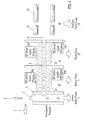
- Fig. 3 illustrates an embodiment of the present invention wherein hexapole ion guide 6 has been replaced with an ion tunnel 15 according to the preferred embodiment.
- the other components of the mass spectrometer are substantially the same as described in relation to Fig. 2 and hence will not be described again.
- the ion tunnel 15 exhibits an improved transmission efficiency of approximately 75% compared with using hexapole ion guide 6 and the ion tunnel 15 does not suffer from as narrow a m/z bandpass transmission efficiency as is reported with ion funnels.
- the reference potential of the ion tunnel 15 is preferably maintained at 0-2 V dc above the dc potential of the wall forming the differential pumping aperture 11 which is preferably either at ground (0 V dc) or around 40-240 V dc depending upon the mass analyser used.
- the wall forming differential pumping aperture 11 may, of course, be maintained at other dc potentials.
- the hexapole ion guide 9 may be replaced by an ion tunnel 15' with hexapole ion guide 6 being maintained.
- Fig. 4 shows a particularly preferred embodiment of the present invention wherein both hexapole ion guides 6,9 have been replaced with ion tunnels 15,15'.
- the ion tunnels 15,15' are about 13 cm in length and preferably comprise approximately 85 ring electrodes.
- the ion tunnel 15 in vacuum chamber 18 is preferably maintained at a pressure ⁇ 1 mbar and is supplied with an rf-voltage at a frequency ⁇ 1 MHz
- the ion tunnel 15' in vacuum chamber 19 is preferably maintained at a pressure of 10 -3 -10 -2 mbar and is supplied with an rf-voltage at a frequency ⁇ 2 MHz.
- Rf frequencies of 800 kHz - 3 MHz could also be used for both ion tunnels 15,15' according to further embodiments of the present invention.
- the ion tunnel 15' exhibits an improved transmission efficiency of approximately 25%, and hence the combination of ion tunnels 15,15' exhibit an improved transmission efficiency of approximately 100% compared with using hexapole ion guide 6 in combination with hexapole ion guide 9.
- Figs. 5 and 6 show a particularly preferred embodiment of the present invention.
- the AC-only ion guide comprises two interleaved comb-like arrangements of electrodes.
- Each comb comprises a plurality of electrodes 15a;15b, each electrode 15a;15b having an aperture.
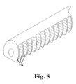
- One of the combs is shown in more detail in Fig. 5 .
- the comb comprises a longitudinally extending bar or spine from which a number of electrodes 15a;15b depend therefrom.
- the electrodes 15a;15b may either be integral with the bar or spine, or alternatively they may be electrically connected to the bar or spine.
- Each electrode 15a;15b preferably has a substantially circular aperture. However, as can be seen from Fig.
- each electrode 15a;15b in cross-section is preferably a truncated circular shape.
- Fig. 6 shows in more detail how the two combs are interleaved. Various insulating rings are also shown which help to hold the assembly together.
- the comb like arrangement of electrodes 15a;15b may be provided in input vacuum chamber 18 and/or intermediate vacuum chamber 19.
- the arrangements shown in Figs. 5 and 6 are intended to fall within the scope of the claims.
- a further embodiment is also contemplated comprising three interleaved combs connected to a 3-phase AC generator.
Landscapes
- Chemical & Material Sciences (AREA)
- Analytical Chemistry (AREA)
- Other Investigation Or Analysis Of Materials By Electrical Means (AREA)
- Electron Tubes For Measurement (AREA)
- Crystals, And After-Treatments Of Crystals (AREA)
- Analysing Materials By The Use Of Radiation (AREA)
Abstract
Description
- The present invention relates to a mass spectrometer and a method of mass spectrometry.
- Ion guides comprising rf-only multipole rod sets such as quadruplets, hexapoles and octopoles are well known.
- An alternative type of ion guide known as an "ion funnel" has recently been proposed by Smith and co-workers at Pacific Northwest National Laboratory. An ion funnel comprises a stack of ring electrodes of constant external diameter but which have progressively smaller internal apertures. A dc voltage/potential gradient is applied along the length of the ion guide in order to urge ions through the ion funnel which would otherwise act as an ion mirror.
- A variant of the standard ion funnel arrangement is disclosed in Anal. Chem. 2000, 72, 2247-2255 and comprises an initial drift section comprising ring electrodes having constant internal diameters and a funnel section comprising ring electrodes having uniformly decreasing internal diameters. A dc voltage gradient is applied across both sections in order to urge ions through the ion funnel.
- Ion funnels have not been successfully employed in commercial mass spectrometers to date.
- One reason for this may be that ion funnels suffer from a narrow bandpass transmission efficiency i.e. the ion funnel may, for example, only efficiently transmit ions having mass to charge ratios ("m/z") falling within a narrow range e.g. 100 < m/z < 200. Reference is made, for example, to
Figs. 5A and 5B of Anal. Chem. 1998, 70, 4111-4119 wherein experimental results are presented comparing observed mass spectra obtained using an ion funnel with that obtained using a conventional ion guide. The experimental results show that both relatively low m/z and relatively high m/z ions fail to be transmitted by the ion funnel. Reference is also made to pages 2249 and 2250 of Anal. Chem 2000, 72, 2247-2255 which similarly recognises that ion funnels suffer from an undesirably narrow m/z transmission window. - Another reason may be that ion funnel ion guides require both an rf voltage and a dc voltage gradient to be applied to the ring electrodes. However, the design and manufacture of a reliable power supply capable of supplying both an rf voltage and a dc voltage gradient which is decoupled from the rf voltage is a non-trivial matter and increases the overall manufacturing cost of the mass spectrometer.
- It is therefore desired to provide an improved ion guide.
- According to an aspect of the present invention there is provided a mass spectrometer as claimed in
claim 1. - According to another aspect of the present invention there is provided a method of mass spectrometry as claimed in
claim 15. - The preferred embodiment comprises a plurality of electrodes wherein most if not all of the electrodes have apertures which are substantially the same size. The apertures are preferably circular in shape, and the outer circumference of the electrodes may also be circular. In one embodiment the electrodes may comprise ring or annular electrodes. However, the outer circumference of the electrodes does not need to be circular and embodiments of the present invention are contemplated wherein the outer profile of the electrodes may take on other shapes. The preferred embodiment wherein the internal apertures of each of the electrodes are either identical or substantially similar is referred to hereinafter as an "ion tunnel" in contrast to ion funnels which have ring electrodes with internal apertures which become progressively smaller in size.
- One advantage of the preferred embodiment is that the ion guide does not suffer from a narrow or limited mass to charge ratio transmission efficiency which appears to be inherent with ion funnel arrangements.
- Another advantage of the preferred embodiment is that a dc voltage gradient is not and does not need to be applied to the ion guide. The resulting power supply for the ion guide can therefore be significantly simplified compared with that required for an ion funnel thereby saving costs and increasing reliability.
- An additional advantage of the preferred embodiment is that it has been found to exhibit an approximately 75% improvement in ion transmission efficiency compared with a conventional multipole, e.g. hexapole, ion guide. The reasons for this enhanced ion transmission efficiency are not fully understood, but it is thought that the ion tunnel may have a greater acceptance angle and a greater acceptance area than a comparable multipole rod set ion guide.
- The preferred ion guide therefore represents a significant improvement over other known ion guides.
- Various types of ion optical devices other than an ion tunnel ion guide are known including multipole rod sets, Einzel lenses, segmented multipoles, short (solid) quadrupole pre/post filter lenses ("stubbies"), 3D quadrupole ion traps comprising a central doughnut shaped electrode together with two concave end cap electrodes, and linear (2D) quadrupole ion traps comprising a multipole rod set with entrance and exit ring electrodes. However, such devices are not intended to fall within the scope of the present invention.
- According to the preferred embodiment, the input vacuum chamber is arranged to be maintained at a relatively high pressure i.e. at least a few mbar. According to an embodiment, the input vacuum chamber may be arranged to be maintained at a pressure above a minimum value and less than or equal to a maximum value such as 20 or 30 mbar.
- Embodiments of the present invention are also contemplated, wherein if the AC-only ion guide is considered to have a length L and is maintained in the input vacuum chamber at a pressure P, then the pressure-length product p x L is selected from the group comprising: (i) ≥ 1 mbar cm; (ii) ≥ 2 mbar cm; (iii) ≥ 5 mbar cm; (iv) ≥ 10 mbar cm; (v) ≥ 15 mbar cm; (vi) ≥ 20 mbar cm; (vii) ≥ 25 mbar cm; (viii) ≥ 30 mbar cm; (ix) ≥ 40 mbar cm; (x) ≥ 50 mbar cm; (xi) ≥ 60 mbar cm; (xii) ≥ 70 mbar cm; (xiii) ≥ 80 mbar cm; (xiv) ≥ 90 mbar cm; (xv) ≥. 100 mbar cm; (xvi) ≥ 110 mbar cm; (xvii) ≥ 120 mbar cm; (xviii) ≥ 130 mbar cm; (xix) ≥ 140 mbar cm; (xx) ≥ 150 mbar cm; (xxi) ≥ 160 mbar cm; (xxii) ≥ 170 mbar cm; (xxiii) ≥ 180 mbar cm; (xxiv) ≥ 190 mbar cm; and (xxv) ≥ 200 mbar cm.
- The electrodes are preferably relatively thin e.g. ≤ 2 mm, further preferably ≤ 1 mm, further preferably 0.5 ± 0.2 mm, further preferably 0.7 ± 0.1 mm thick. According to a particularly preferred embodiment the electrodes have a thickness within the range 0,5-0.7 mm in contrast to multipole rod sets which are typically > 10 cm long.
- Each, or at least a majority of the electrodes forming the AC-only ion guide may comprise either a plate having an aperture therein, or a wire or rod bent to form a closed ring or a nearly closed ring. The outer profile of the electrodes may or may not be circular.
- Preferably, alternate electrodes are connected together and to one of the output connections of a single AC generator.
- The AC-only ion guide preferably comprises at least 4, 5, 6, 7, 8, 9, 10, 20, 30, 40, 50, 60, 70, 80, 90 or 100 electrodes.
- The electrodes forming the AC-only ion guide may have internal diameters or dimensions selected from the group comprising: (i) ≤ 5.0 mm; (ii) ≤ 4.5 mm; (iii) ≤ 4.0 mm; (iv) ≤ 3.5 mm; (v) ≤ 3.0 mm; (vi) ≤ 2.5 mm; (vii) 3.0 ± 0.5 mm; (viii) ≤ 10.0 mm; (ix) ≤ 9.0 mm; (x) ≤ 8.0 mm; (xi) ≤ 7.0 mm; (xii) ≤ 6.0 mm; (xiii) 5.0 ± 0.5 mm; and (xiv) 4-6 mm.
- The length of the AC-only ion guide may be selected from the group comprising: (i) ≥ 100 mm; (ii) ≥ 120 mm; (iii) ≥ 150 mm; (iv) 130 ± 10 mm; (v) 100-150 mm; (vi) ≤ 160 mm; (vii) ≤ 180 mm; (viii) ≤ 200 mm; (ix) 130-150 mm; (x) 120-180 mm; (xi) 120-140 mm; (xii) 130 mm ± 5, 10, 15, 20, 25 or 30 mm; (xiii) 50-300 mm; (xiv) 150-300 mm; (xv) ≥ 50 mm; (xvi) 50-100 mm; (xvii) 60-90 mm; (xviii) ≥ 75 mm; (xix) 50-75 mm; and (xx) 75-100 mm.
- Preferably, an intermediate vacuum chamber may be disposed between the input vacuum chamber and the analyzer vacuum chamber, the intermediate vacuum chamber comprising an AC-only ion guide for transmitting ions through the intermediate vacuum chamber, the AC-only ion guide arranged in the intermediate vacuum chamber comprising a plurality of electrodes having apertures, the apertures being aligned so that ions travel through them as they are transmitted by the ion guide. At least one further differential pumping apertured electrode is provided through which ions may pass. The further differential pumping apertured electrode is disposed between the vacuum chambers to allow the intermediate vacuum chamber to be maintained at a lower pressure than the input vacuum chamber, and the analyzer vacuum chamber to be maintained at a lower pressure than the intermediate vacuum chamber. An alternating current (AC) generator is connected to an intermediate chamber reference potential for providing AC potentials to the AC-only ion guide in the intermediate vacuum chamber.
- Preferably, at least 90%, and preferably 100%, of the apertures of the electrodes forming the AC-only ion guide in the intermediate vacuum chamber are substantially the same size, and at least 90%, and preferably 100%, of the plurality of the electrodes forming the AC-only ion guide in the intermediate vacuum chamber are connected to the AC generator connected to the intermediate chamber reference potential in such a way that at any instant during an AC cycle of the output of the AC generator, adjacent ones of the electrodes forming the AC-only ion guide arranged in the intermediate vacuum chamber are supplied respectively with approximately equal positive and negative potentials relative to the intermediate chamber reference potential.
- Preferably, the AC-only ion guide in the intermediate vacuum chamber comprises at least 4, 5, 6, 7, 8, 9, 10, 20, 30, 40, 50, 60, 70, 80, 90, or 100 electrodes.
- Preferably, the intermediate vacuum chamber is arranged to be maintained at a pressure selected from the group comprising: (i) 10-3-10-2 mbar; (ii) ≥ x 10-3 mbar; (iii) ≥ 5 x 10⁻³ mbar; (iv) ≤ 10-2 mbar; (v) 10-3-5 x 10⁻³ mbar; and (vi) 5 x 10⁻³-10-2 mbar.
- Preferably, the electrodes forming the AC-only ion guide in the intermediate vacuum chamber have internal diameters or dimensions selected from the group comprising: (i) ≤ 5.0 mm; (ii) ≤ 4.5 mm; (iii) ≤ 4.0 mm; (iv) ≤ 3.5 mm; (v) ≤ 3.0 mm; (vi) ≤ 2.5 mm; (vii) 3.0 ± 0.5 mm; (viii) ≤ 10.0 mm; (ix) ≤ 9.0 mm; (x) ≤ 8.0 mm; (xi) ≤ 7.0 mm; (xii) ≤ 6.0 mm; (xiii) 5.0 ± 0.5 mm; and (xiv) 4-6 mm.
- In one embodiment the individual electrodes in the AC-only ion guide in the input vacuum chamber and/or the AC-only ion guide in the intermediate vacuum chamber preferably have a substantially circular aperture having a diameter selected from the group comprising: (i) 0.5-1.5 mm; (ii) 1.5-2.5 mm; (iii) 2.5-3.5 mm; (iv) 3.5-4.5 mm; (v) 4.5-5.5 mm; (vi) 5.5-6.5 mm; (vii) 6.5-7.5 mm; (viii) 7.5-8.5 mm; (ix) 8.5-9.5 mm; (x) 9.5-10.5 mm; and (xi) < 10 mm.
- Preferably, the length of the ion guide in the intermediate vacuum chamber is selected from the group comprising: (i) ≥ 100 mm; (ii) ≥ 120 mm; (iii) ≥ 150 mm; (iv) 130± 10 mm; (v) 100-150 mm; (vi) ≤ 160 mm; (vii) ≤ 180 mm; (viii) ≤ 200 mm; (ix) 130-150 mm; (x) 120-180 mm; (xi) 120-140 mm; (xii) 130 mm ± 5, 10, 15, 20, 25 or 30 mm; (xiii) 50-300 mm; (xiv) 150-300 mm; (xv) ≥ 50 mm; (xvi) 50-100 mm; (xvii) 60-90 mm; (xviii) ≥ 75 mm; (xix) 50-75 mm; and (xx) 75-100 mm.
- Preferably, the ion source is an atmospheric pressure ion source.
- Preferably, the ion source is a continuous ion source.
- An Electrospray ("ES") ion source or an Atmospheric Pressure Chemical Ionisation ("APCI") ion source is particularly preferred. However, other embodiments are also contemplated wherein the ion source is either an Inductively Coupled Plasma ("ICP") ion source or a Matrix Assisted Laser Desorption lonisation ("MALDI") ion source at low vacuum or at atmospheric pressure.
- Preferably, the ion mass analyser is selected from the group comprising: (i) a Time of Flight mass analyser, preferably an orthogonal Time of flight mass analyser; (ii) a quadrupole mass analyser; and (iii) a quadrupole ion trap.
- Preferably, the AC-only ion guide comprises two interleaved comb arrangements, each comb arrangement comprising a plurality of electrodes having apertures.
- Preferably, the AC-only ion guide comprises at least one comb arrangement comprising a longitudinally extending member having a plurality of electrodes having apertures depending therefrom.
- Preferably, the input vacuum chamber has a length and the comb arrangement extends at least x% of the length, x% selected from the group comprising: (i) ≥50%; (ii) ≥ 60%; (iii) ≥ 70%; (iv) ≥ 80%; (v) ≥ 90%; and (vi) ≥ 95%.
- According to an aspect of the present invention there is provided a mass spectrometer comprising:
- an ion source for producing ions;
- an input vacuum chamber comprising at least one AC ion guide for transmitting the ions, wherein the AC ion guide comprises two interleaved comb arrangements, each the comb arrangement comprising a plurality of electrodes having apertures;
- an analyzer vacuum chamber comprising a mass analyzer disposed to receive ions after they have been transmitted by the ion guide; and
- at least one differential pumping apertured electrode through which ions may pass, the at least one differential pumping apertured electrode being disposed between the input vacuum chamber and the analyzer vacuum chamber to permit the analyzer vacuum chamber to be maintained at a lower pressure than the input vacuum chamber.
- Preferably, at least 90% or 100% of the apertures are substantially the same size.
- The plurality of electrodes forming the AC ion guide are preferably connected to an AC generator in such a way that at any instant during an AC cycle of the output of the AC generator, adjacent ones of the electrodes are supplied respectively with approximately equal positive and negative potentials relative to an input chamber reference potential.
- Each comb arrangement preferably comprises a longitudinally extending member having a plurality of electrodes having apertures depending therefrom.
- The input vacuum chamber preferably has a length and the comb arrangements extend at least x% of the length, x% selected from the group consisting of: (i) ≥ 50%; (ii) ≥ 60%; (iii) ≥ 70%; (iv) ≥ 80%; (v) ≥ 90%; and (vi) ≥ 95%.
- Alternate ones of the electrodes are preferably connected to each other and to one of the output connections of a single AC generator.
- The AC ion guide preferably comprises at least 4, 5, 6, 7, 8, 9, 10, 20, 30, 40, 50, 60, 70, 80, 90, or 100 electrodes.
- The electrodes preferably have internal diameters or dimensions selected from the group consisting of: (i) ≤ 5.0 mm; (ii) ≤ 4.5 mm; (iii) ≤ 4.0 mm; (iv) ≤ 3.5 mm; (v) ≤ 3.0 mm; (vi) ≤ 2.5 mm; (vii) 3.0 ± 0.5 mm; (viii) ≤ 10.0 mm; (ix) ≤ 9.0 mm; (x) ≤ 8.0 mm; (xi) ≤ 7.0 mm; (xii) ≤ 6.0 mm; (xiii) 5.0 ± 0.5 mm; and (xiv) 4-6 mm.
- The length of the AC ion guide is preferably selected from the group consisting of: (i) ≥ 100 mm; (ii) ≥ 120 mm; (iii) ≥ 150 mm; (iv) 130 ± 10 mm; (v) 100-150 mm; (vi) ≤ 160 mm; (vii) ≤ 180 mm; (viii) ≤ 200 mm; (ix) 130-150 mm; (x) 120-180 mm; (xi) 120-140 mm; (xii) 130 mm ± 5, 10, 15, 20, 25 or 30 mm; (xiii) 50-300 mm; (xiv) 150-300 mm; (xv) ≥ 50 mm; (xvi) 50-100 mm; (xvii) 60-90 mm; (xviii) ≥ 75 mm; (xix) 50-75 mm; (xx) 75-100 mm; (xxi) 150-200 mm; (xxii) ≥ 200 mm; and (xxiii) 50-200 mm.
- The mass spectrometer preferably further comprises:
- an intermediate vacuum chamber disposed between the input vacuum chamber and the analyzer vacuum chamber, the intermediate vacuum chamber comprising an AC ion guide for transmitting ions through the intermediate vacuum chamber, the AC ion guide arranged in the intermediate vacuum chamber comprising a plurality of electrodes having apertures, the apertures being aligned so that ions travel through them as they are transmitted by the ion guide;
- at least one further differential pumping apertured electrode through which ions may pass, disposed between the vacuum chambers to allow the intermediate vacuum chamber to be maintained at a lower pressure than the input vacuum chamber, and the analyzer vacuum chamber to be maintained at a lower pressure than the intermediate vacuum chamber; and
- an alternating current (AC) generator connected to an intermediate chamber reference potential for providing AC potentials to the AC ion guide in the intermediate vacuum chamber.
- Preferably, at least 90% or 100% of the apertures of the electrodes forming the AC ion guide in the intermediate vacuum chamber are substantially the same size; and
at least 90% or 100% of the plurality of the electrodes forming the AC ion guide in the intermediate vacuum chamber are connected to the AC generator connected to the intermediate chamber reference potential in such a way that at any instant during an AC cycle of the output of the AC generator, adjacent ones of the electrodes forming the AC ion guide arranged in the intermediate vacuum chamber are supplied respectively with approximately equal positive and negative potentials relative to the intermediate chamber reference potential. - The AC ion guide in the intermediate vacuum chamber preferably comprises at least 4, 5, 6, 7, 8, 9, 10, 20, 30, 40, 50, 60, 70, 80, 90, or 100 electrodes.
- The intermediate vacuum chamber is preferably arranged to be maintained at a pressure selected from the group consisting of: (i) 10-3-10-2 mbar; (ii). 2 x 10⁻³ mbar; (iii), 5 x 10⁻³ mbar; (iv). 10-2 mbar; (v) 10-3-5 x 10⁻³ mbar; and (vi) 5 x 10⁻³-10-2 mbar.
- Electrodes forming the AC ion guide in the intermediate vacuum chamber preferably have internal diameters or dimensions selected from the group consisting of: (i) ≤ 5.0 mm; (ii) ≤ 4.5 mm; (iii) ≤ 4.0 mm; (iv) ≤ 3.5 mm; (v) ≤ 3.0 mm; (vi) ≤ 2.5 mm; (vii) 3.0 ± 0.5 mm; (viii) ≤ 10.0 mm; (ix) ≤ 9.0 mm; (x) ≤ 8.0 mm; (xi) ≤ 7.0 mm; (xii) ≤ 6.0 mm; (xiii) 5.0 ± 0.5 mm; and (xiv) 4-6 mm.
- The length of the ion guide in the intermediate vacuum chamber is preferably selected from the group consisting of: (i) ≥ 100 mm; (it) ≥ 120 mm; (iii) ≥ 150 mm; (iv) 130 ± 10 mm; (v) 100-150 mm,; (vi) ≤ 160 mm; (vii) ≤ 180 mm; (viii) ≤ 200 mm; (ix) 130-150 mm; (x) 120-180 mm; (xi) 120-140 mm; (xii) 130 mm ± 5, 10, 15, 20, 25 or 30 mm; (xiii) 50-300 mm; (xiv) 150-300 mm; (xv) ≥ 50 mm; (xvi) 50-100 mm; (xvii) 60-90 mm; (xviii) ≥ 75 mm; (xix) 50-75 mm; (xx) 75-100 mm; (xxi) 150-200 mm; (xxii) ≥ 200 mm; and (xxiii) 50-200 mm.
- The ion source is preferably an atmospheric pressure ion source.
- The ion source is preferably a continuous ion source.
- According to an embodiment the ion source is an Electrospray ("ES") ion source or an Atmospheric Pressure Chemical lonisation ("APCI") ion source.
- According to an embodiment the ion source is an Inductively Coupled Plasma ("ICP") ion source.
- According to an embodiment the ion source is a Matrix Assisted Laser Desorption lonisation ("MALDI") ion source.
- The ion mass analyser is preferably selected from the group comprising: (i) a Time of Flight mass analyser, (ii) an orthogonal Time of Flight mass analyser; (iii) a quadrupole mass analyser; and (iv) a quadrupole ion trap.
- The input vacuum chamber is preferably arranged to be maintained at a pressure selected from the group consisting of: (i) ≥ 0.1 mbar; (ii) ≥ 0.5 mbar; (iii) ≥ 0.7 mbar; (iv) ≥ 1.0 mbar; (v) ≥ 1.3 mbar; (vi) ≥ 1.5 mbar; (vii) ≥ 2.0 mbar; (viii) ≥ 2.5 mbar; (ix) ≥ 3.0 mbar; (x) ≥ 3.5 mbar; (xi) ≥ 4.0 mbar; (xii) ≥ 4.5 mbar; (xiii) ≥ 5.0 mbar; (xiv) ≥ 6.0 mbar; (xv) ≥ 7.0 mbar; (xvi) ≥ 8.0 mbar; (xvii) ≥ 9.0 mbar; (xviii) ≥ 10.0 mbar; (xix) 1-5 mbar; (xx) 1-2 mbar; and (xxi) 0.5-1.5 mbar.
- The input vacuum chamber is arranged to be maintained at a pressure selected from the group consisting of: (i) ≤ 20 mbar; and (ii) ≤ 30 mbar.
- If the AC ion guide has a length L and is maintained in the input vacuum chamber at a pressure P, then the pressure-length product p x L is preferably selected from the group consisting of: (i) ≥ 1 mbar cm; (ii) ≥ 2 mbar cm; (iii) ≥ 5 bar cm; (iv) ≥ 10 mbar cm; (v) ≥ 15 mbar cm; (vi) ≥ 20 mbar cm; (vii) ≥ 25 mbar cm; (viii) ≥ 30 mbar cm; (ix) ≥ 40 mbar cm; (x) ≥ 50 mbar cm; (xi) ≥ 60 mbar cm; (xii) ≥ 70 mbar cm; (xiii) ≥ 80 mbar cm; (xiv) ≥ 90 mbar cm; (xv) ≥ 100 mbar cm; (xvi) ≥ 110 mbar cm; (xvii) ≥ 120 mbar cm; (xviii) ≥ 130 mbar cm; (xix) ≥ 140 mbar cm; (xx) ≥ 150 mbar cm; (xxi) ≥ 160 mbar cm; (xxii) ≥ 170 mbar cm; (xxiii) ≥ 180 mbar cm; (xxiv) ≥ 190 mbar cm; and (xxv) ≥ 200 mbar cm.
- The electrodes forming the AC ion guide preferably have a thickness selected from the group consisting of: (i) ≤ 2 mm; (ii) ≤ 1 mm; (iii) 0.5 ± 0.2 mm; (iv) 0.7 ± 0.1 mm; and (v) 0.5-0.7 mm.
- According to an aspect of the present of the invention a method of mass spectrometry, comprising:
- producing ions from an ion source;
- transmitting at least some of the ions through an input vacuum chamber comprising at least one AC ion guide for transmitting the ions, the AC ion guide comprising two interleaved comb arrangements, each the comb arrangement comprising a plurality of electrodes having apertures;
- passing the ions to an analyzer vacuum chamber comprising a mass analyzer disposed to receive ions after they have been transmitted by the ion guide;
- wherein at least one differential pumping apertured electrode is provided though which ions may pass, the at least one differential pumping apertured electrode being disposed between the input vacuum chamber and the analyzer vacuum chamber to permit the analyzer vacuum chamber to be maintained at a lower pressure than the input vacuum chamber.
- Each comb arrangement preferably comprises a longitudinally extending member having a plurality of electrodes having apertures depending therefrom.
- According to an embodiment the method preferably comprises maintaining the input vacuum chamber at a pressure selected from the group consisting of: (i) ≥ 0.1 mbar; (ii) ≥ 0.5 mbar; (iii) ≥ 0.7 mbar; (iv) ≥ 1.0 mbar; (v) ≥ 1.3 mbar; (vi) ≥ 1.5 mbar; (vii) ≥ 2.0 mbar; (viii) ≥ 2.5 mbar; (ix) ≥ 3.0 mbar; (x) ≥ 3.5 mbar; (xi) ≥ 4.0 mbar; (xii) ≥ 4.5 mbar; (xiii) ≥ 5.0 mbar; (xiv) ≥ 6.0 mbar; (xv) ≥ 7.0 mbar; (xvi) ≥ 8.0 mbar; (xvii) ≥ 9.0 mbar; (xviii) ≥ 10.0 mbar; (xix) 1-5 mbar; (xx) 1-2 mbar; and (xxi) 0.5-1.5 mbar.
- The method preferably further comprises maintaining the input vacuum chamber at a pressure selected from the group consisting of: (i) ≤ 0 mbar; and (ii) ≤ 30 mbar.
- According to an embodiment the method further comprises:
- providing an intermediate vacuum chamber disposed between the input vacuum chamber and the analyzer vacuum chamber, the intermediate vacuum chamber comprising an AC ion guide for transmitting ions through the intermediate vacuum chamber, the AC ion guide arranged in the intermediate vacuum chamber comprising a plurality of electrodes having apertures, the apertures being aligned so that ions travel through them as they are transmitted by the ion guide;
- providing at least one further differential pumping apertured electrode through which ions may pass, disposed between the vacuum chambers to allow the intermediate vacuum chamber to be maintained at a lower pressure than the input vacuum chamber, and the analyzer vacuum chamber to be maintained at a lower pressure than the intermediate vacuum chamber; and
- providing an alternating current (AC) generator connected to an intermediate chamber reference potential for providing AC potentials to the AC ion guide in the intermediate vacuum chamber.
- According to an embodiment the method further comprises maintaining the intermediate vacuum chamber at a pressure selected from the group consisting of: (i) 10-3-10-2 mbar; (ii). 2 x 10⁻³ mbar; (iii). 5 x 10⁻³ mbar; (iv), 10-2 mbar; (v) 10-3-5 x 10⁻³ mbar; and (vi) 5 x 10⁻³-10-2 mbar.
- The method preferably further comprises maintaining the AC ion guide having a length L in the input vacuum chamber at a pressure P, wherein the pressure-length product p x L is selected from the group consisting of: (i) ≥ 1 mbar cm; (ii) ≥ 2 mbar cm; (iii) ≥ 5 bar cm; (iv) ≥ 10 mbar cm; (v) ≥ 15 mbar cm; (vi) ≥ 20 mbar cm; (vii) ≥ 25 mbar cm; (viii) ≥ 30 mbar cm; (ix) ≥ 40 mbar cm; (x) ≥ 50 mbar cm; (xi) ≥ 60 mbar cm; (xii) ≥ 70 mbar cm; (xiii) ≥ 80 mbar cm; (xiv) ≥ 90 mbar cm; (xv) ≥ 100 mbar cm; (xvi) ≥ 110 mbar cm; (xvii) ≥ 120 mbar cm; (xviii) ≥ 130 mbar cm; (xix) ≥ 140 mbar cm; (xx) ≥ 150 mbar cm; (xxi) ≥ 160 mbar cm; (xxii) ≥ 170 mbar cm; (xxiii) ≥ 180 mbar cm; (xxiv) ≥ 190 mbar cm; and (xxv) ≥ 200 mbar cm.
- Various embodiments of the present invention will now be described, by way of example only, and with reference to the accompanying drawings in which:
-
Fig. 1 shows a preferred ion tunnel arrangement; -
Fig. 2 shows a conventional mass spectrometer with an atmospheric pressure ion source and two rf hexapole ion guides disposed in separate vacuum chambers; -
Fig. 3 shows an embodiment of the present invention wherein one of the hexapole ion guides has been replaced with an ion tunnel; -
Fig. 4 shows another embodiment of the present invention wherein both hexapole ion guides have been replaced with ion tunnels; -
Fig. 5 shows a comb arrangement; and -
Fig. 6 shows a particularly preferred embodiment comprising two interleaved comb-like arrangements. - As shown in
Fig. 1 , apreferred ion tunnel 15 comprises a plurality ofelectrodes electrodes electrodes -
Adjacent electrodes ring electrodes 15a may be connected to the 0°phase supply 16a, and the second, fourth, sixth etc.ring electrodes 15b may be connected to the 180°phase supply 16b. In one embodiment the AC power supply may be a RF power supply. However, the present invention is not intended to be limited to RF frequencies. Furthermore, "AC" is intended to mean simply that the waveform alternates and hence embodiments of the present invention are also contemplated wherein non-sinusoidal waveforms including square waves are provided. Ions from an ion source pass through theion tunnel 15 and are efficiently transmitted by it. - In contrast to ion funnels, the dc reference potential about which the AC signal oscillates is substantially the same for each electrode. Unlike ion traps, blocking dc potentials are not applied to either the entrance or exit of the
ion tunnel 15. -
Fig. 2 shows a conventional mass spectrometer. An Electrospray ("ES")ion source 1 or an Atmospheric Pressure Chemical lonisation ("APCI") 1,2 ion source emits ions which enter avacuum chamber 17 pumped by a rotary ormechanical pump 4 via asample cone 3 and a portion of the gas and ions passes through adifferential pumping aperture 21 preferably maintained at 50-120V into avacuum chamber 18 housing an rf-onlyhexapole ion guide 6.Vacuum chamber 18 is pumped by a rotary ormechanical pump 7. Ions are transmitted by the rf-onlyhexapole ion guide 6 through thevacuum chamber 18 and pass through a differential pumping aperture 8 into afurther vacuum chamber 19 pumped by a turbo-molecular pump 10. Thisvacuum chamber 19 houses another rf-only hexapole ion guide 9. Ions are transmitted by rf-only hexapole ion guide 9 throughvacuum chamber 19 and pass throughdifferential pumping aperture 11 into a yetfurther vacuum chamber 20 which is pumped by a turbo-molecular pump 14.Vacuum chamber 20 houses a prefilter rod set 12, a quadrupole mass filter/analyser 13 and may include other elements such as a collision cell (not shown), a further quadrupole mass filter/analyser together with an ion detector (not shown) or a time of flight analyser (not shown). -
Fig. 3 illustrates an embodiment of the present invention whereinhexapole ion guide 6 has been replaced with anion tunnel 15 according to the preferred embodiment. The other components of the mass spectrometer are substantially the same as described in relation toFig. 2 and hence will not be described again. Theion tunnel 15 exhibits an improved transmission efficiency of approximately 75% compared with usinghexapole ion guide 6 and theion tunnel 15 does not suffer from as narrow a m/z bandpass transmission efficiency as is reported with ion funnels. An rf-voltage is applied to the electrodes and the reference potential of theion tunnel 15 is preferably maintained at 0-2 V dc above the dc potential of the wall forming thedifferential pumping aperture 11 which is preferably either at ground (0 V dc) or around 40-240 V dc depending upon the mass analyser used. However, the wall formingdifferential pumping aperture 11 may, of course, be maintained at other dc potentials. - In another less preferred (unillustrated) embodiment, the hexapole ion guide 9 may be replaced by an ion tunnel 15' with
hexapole ion guide 6 being maintained. -
Fig. 4 shows a particularly preferred embodiment of the present invention wherein both hexapole ion guides 6,9 have been replaced withion tunnels 15,15'. Theion tunnels 15,15' are about 13 cm in length and preferably comprise approximately 85 ring electrodes. Theion tunnel 15 invacuum chamber 18 is preferably maintained at a pressure ≥ 1 mbar and is supplied with an rf-voltage at a frequency ∼ 1 MHz, and the ion tunnel 15' invacuum chamber 19 is preferably maintained at a pressure of 10-3-10-2 mbar and is supplied with an rf-voltage at a frequency ∼ 2 MHz. Rf frequencies of 800 kHz - 3 MHz could also be used for bothion tunnels 15,15' according to further embodiments of the present invention. - The ion tunnel 15' exhibits an improved transmission efficiency of approximately 25%, and hence the combination of
ion tunnels 15,15' exhibit an improved transmission efficiency of approximately 100% compared with usinghexapole ion guide 6 in combination with hexapole ion guide 9. -
Figs. 5 and6 show a particularly preferred embodiment of the present invention. The AC-only ion guide comprises two interleaved comb-like arrangements of electrodes. Each comb comprises a plurality ofelectrodes 15a;15b, eachelectrode 15a;15b having an aperture. One of the combs is shown in more detail inFig. 5 . As can be seen, the comb comprises a longitudinally extending bar or spine from which a number ofelectrodes 15a;15b depend therefrom. Theelectrodes 15a;15b may either be integral with the bar or spine, or alternatively they may be electrically connected to the bar or spine. Eachelectrode 15a;15b preferably has a substantially circular aperture. However, as can be seen fromFig. 5 , in cross-section the outer profile of eachelectrode 15a;15b is preferably a truncated circular shape.Fig. 6 shows in more detail how the two combs are interleaved. Various insulating rings are also shown which help to hold the assembly together. The comb like arrangement ofelectrodes 15a;15b may be provided ininput vacuum chamber 18 and/orintermediate vacuum chamber 19. For the avoidance of any doubt, the arrangements shown inFigs. 5 and6 are intended to fall within the scope of the claims. A further embodiment is also contemplated comprising three interleaved combs connected to a 3-phase AC generator.
Claims (15)
- A mass spectrometer comprising:an ion source (1) for producing ions;an input vacuum chamber (18) comprising at least one ion guide (15) for transmitting said ions, said ion guide (15) comprising a plurality of electrodes having apertures;an analyzer vacuum chamber (20) comprising a mass analyzer (13);an intermediate vacuum chamber (19) disposed between said input vacuum chamber (18) and said analyser vacuum chamber (20);at least one differential pumping apertured electrode (8) disposed between said input vacuum chamber (18) and said intermediate vacuum chamber (19); andat least one further differential pumping apertured electrode (11) disposed between said intermediate vacuum chamber (19) and said analyser vacuum chamber (20);characterised in that:said ion guide (15) comprises an AC-only ion tunnel ion guide (15).
- A mass spectrometer as claimed in claim 1, wherein said electrodes have internal diameters or dimensions selected from the group comprising: (i) ≥ 10.0 mm; (ii) ≤ 9.0 mm; (iii) ≤ 8.0 mm; (iv) ≤ 7.0 mm; (v) ≤ 6.0 mm; (vi) ≤ 5.0 mm; (vii) ≤ 4.5 mm; (viii) ≤ 4.0 mm; (ix) ≤ 3.5 mm; (x) ≤ 3.0 mm; and (xi) ≤ 2.5 mm.
- A mass spectrometer as claimed in claim 1 or 2, wherein at least 90% or 100% of said apertures are substantially the same size.
- A mass spectrometer as claimed in claim 1 or 2, wherein said plurality of electrodes forming said AC ion guide are connected to an AC generator in such a way that at any instant during an AC cycle of the output of said AC generator, adjacent ones of said electrodes are supplied respectively with approximately equal positive and negative potentials relative to an input chamber reference potential.
- A mass spectrometer as claimed in any preceding claim, wherein alternate ones of said electrodes are connected to each other and to one of the output connections of a single AC generator.
- A mass spectrometer as claimed in any preceding claim, wherein the AC ion guide comprises at least 4, 5, 6, 7, 8, 9, 10, 20, 30, 40, 50, 60, 70, 80, 90, or 100 electrodes.
- A mass spectrometer as claimed in any preceding claim, wherein said electrodes have internal diameters or dimensions selected from the group consisting of: (i) ≤ 5.0 mm; (ii) ≤ 4.5 mm; (iii) ≤ 4.0 mm; (iv) ≤ 3.5 mm; (v) ≤ 3.0 mm; (vi) ≤ 2.5 mm; (vii) 3.0 ± 0.5 mm; (viii) ≤ 10.0 mm; (ix) ≤ 9.0 mm; (x) ≤ 8.0 mm; (xi) ≤ 7.0 mm; (xii) ≤ 6.0 mm; (xiii) 5.0 ± 0.5 mm; and (xiv) 4-6 mm.
- A mass spectrometer as claimed in any preceding claim, wherein the length of said AC ion guide is selected from the group consisting of: (i) ≥ 100 mm; (ii) ≥ 120 mm; (iii) ≥ 150 mm; (iv) 130 ± 10 mm; (v) 100-150 mm; (vi) ≤ 160 mm; (vii) ≤ 180 mm; (viii) ≤ 200 mm; (ix) 130-150 mm; (x) 120-180 mm; (xi) 120-140 mm; (xii) 130 mm ± 5, 10, 15, 20, 25 or 30 mm; (xiii) 50-300 mm; (xiv) 150-300 mm; (xv) ≥ 50 mm; (xvi) 50-100 mm; (xvii) 60-90 mm; (xviii) ≥ 75 mm; (xix) 50-75 mm; (xx) 75-100 mm; (xxi) 950-200 mm; (xxii) ≥ 200 mm; and (xxiii) 50-200 mm.
- A mass spectrometer as claimed in any preceding claim, wherein said intermediate vacuum chamber (19) comprises an AC ion guide (15') for transmitting ions through said intermediate vacuum chamber (19), said AC ion guide (15') arranged in said intermediate vacuum chamber (19) comprising a plurality of electrodes having apertures, the apertures being aligned so that ions travel through them as they are transmitted by said ion guide; and
wherein said mass spectrometer further comprises an alternating current (AC) generator connected to an intermediate chamber reference potential for providing AC potentials to the AC ion guide (15') in said intermediate vacuum chamber (19). - A mass spectrometer as claimed in claim 9, wherein
at least 90% or 100% of the apertures of the electrodes forming said AC ion guide (15') in said intermediate vacuum chamber (19) are substantially the same size; and
at least 90% or 100% of said plurality of the electrodes forming said AC ion guide (15') in said intermediate vacuum chamber (19) are connected to the AC generator connected to said intermediate chamber reference potential in such a way that at any instant during an AC cycle of the output of the AC generator, adjacent ones of said electrodes forming said AC ion guide (15') arranged in said intermediate vacuum chamber (19) are supplied respectively with approximately equal positive and negative potentials relative to said intermediate chamber reference potential. - A mass spectrometer as claimed in any preceding claim, wherein said ion source (1) is an atmospheric pressure ion source.
- A mass spectrometer as claimed in any preceding claim, wherein:(a) said input vacuum chamber (18) is arranged to be maintained at a pressure selected from the group consisting of: (i) ≥ 0.1 mbar; (ii) ≥ 0.5 mbar; (iii) ≥ 0.7 mbar; (iv) ≥ 1.0 mbar; (v) ≥ 1.3 mbar; (vi) ≥ 1.5 mbar; (vii) ≥ 2.0 mbar; (viii) ≥ 2.5 mbar; (ix) ≥ 3.0 mbar; (x) ≥ 3.5 mbar; (xi) ≥ 4.0 mbar; (xii) ≥ 4.5 mbar; (xiii) ≥ 5.0 mbar; (xiv) ≥ 6.0 mbar; (xv) ≥ 7.0 mbar; (xvi) ≥ 8.0 mbar; (xvii) ≥ 9.0 mbar; (xviii) ≥ 10.0 mbar; (xix) 1-5 mbar; (xx) 1-2 mbar; and (xxi) 0.5-1.5 mbar; and/or(b) said input vacuum chamber (18) is arranged to be maintained at a pressure selected from the group consisting of: (i) ≥ 20 mbar; and (ii) ≤ 30 mbar.
- A mass spectrometer as claimed in any preceding claim, wherein if said AC-only ion guide is considered to have a length L and is maintained in the input vacuum chamber (18) at a pressure P, then the pressure-length product p x L is selected from the group comprising: (i) ≥ 1 mbar cm; (ii) ≥ 2 mbar cm; (iii) ≥ 5 mbar cm; (iv) ≥ 10 mbar cm; (v) ≥ 15 mbar cm; (vi) ≥ 20 mbar cm; (vii) ≥ 25 mbar cm; (viii) ≥ 30 mbar cm; (ix) ≥ 40 mbar cm; (x) ≥ 50 mbar cm; (xi) ≥ 60 mbar cm; (xii) ≥ 70 mbar cm; (xiii) ≥ 80 mbar cm; (xiv) ≥ 90 mbar cm; (xv) ≥ 100 mbar cm; (xvi) ≥ 110 mbar cm; (xvii) ≥ 120 mbar cm; (xviii) ≥ 130 mbar cm; (xix) ≥ 140 mbar cm; (xx) ≥ 150 mbar cm; (xxi) ≥ 160 mbar cm; (xxii) ≥ 170 mbar cm; (xxiii) ≥ 180 mbar cm; (xxiv) ≥ 190 mbar cm; and (xxv) ≥ 200 mbar cm.
- A method of mass spectrometry comprising:providing an ion source (1) for producing ions;providing an input vacuum chamber (18) comprising at least one ion guide (15) for transmitting said ions, said ion guide (15) comprising a plurality of electrodes having apertures;providing an analyzer vacuum chamber (20) comprising a mass analyzer (13);providing an intermediate vacuum chamber (19) disposed between said input vacuum chamber (18) and said analyser vacuum chamber (20);providing at least one differential pumping apertured electrode (8) disposed between said input vacuum chamber (18) and said intermediate vacuum chamber (19); andproviding at least one further differential pumping apertured electrode (11) disposed between said intermediate vacuum chamber (19) and said analyser vacuum chamber (20);characterised in that:said ion guide (15) comprises an AC-only ion tunnel ion guide (15).
- A method of mass spectrometry as claimed in claim 14, wherein said electrodes have internal diameters or dimensions selected from the group comprising: (i) ≤ 10.0 mm; (ii) ≤ 9.0 mm; (iii) ≤ 8.0 mm; (iv) ≤ 7.0 mm; (v) ≤ 6.0 mm; (vi) ≤ 5.0 mm; (vii) ≤ 4.5 mm; (viii) ≤ 4,0 mm; (ix) ≤ 3.5 mm; (x) ≤ 3.0 mm; and (xi) ≤ 2.5 mm.
Applications Claiming Priority (6)
| Application Number | Priority Date | Filing Date | Title |
|---|---|---|---|
| GBGB0029088.2A GB0029088D0 (en) | 2000-11-29 | 2000-11-29 | Ion tunnel |
| GBGB0109760.9A GB0109760D0 (en) | 2000-11-29 | 2001-04-20 | Mass spectrometers and methods of mass spectrometry |
| GB0110149A GB0110149D0 (en) | 2000-11-29 | 2001-04-25 | Mass spectrometers and methods of mass spectrometry |
| GBGB0120028.6A GB0120028D0 (en) | 2000-11-29 | 2001-08-16 | Mass spectrometers and methods of mass spectrometry |
| EP04026520A EP1505635B1 (en) | 2000-11-29 | 2001-11-29 | Mass spectrometers and methods of mass spectrometry |
| EP01310026A EP1215712B1 (en) | 2000-11-29 | 2001-11-29 | Mass spectrometer and methods of mass spectrometry |
Related Parent Applications (2)
| Application Number | Title | Priority Date | Filing Date |
|---|---|---|---|
| EP01310026.8 Division | 2001-11-29 | ||
| EP04026520.9 Division | 2004-11-09 |
Publications (1)
| Publication Number | Publication Date |
|---|---|
| EP2302661A1 true EP2302661A1 (en) | 2011-03-30 |
Family
ID=9904092
Family Applications (2)
| Application Number | Title | Priority Date | Filing Date |
|---|---|---|---|
| EP04026520A Expired - Lifetime EP1505635B1 (en) | 2000-11-29 | 2001-11-29 | Mass spectrometers and methods of mass spectrometry |
| EP20100183535 Withdrawn EP2302661A1 (en) | 2000-11-29 | 2001-11-29 | Mass spectrometer comprising an ion tunnel ion guide, method of mass spectrometry |
Family Applications Before (1)
| Application Number | Title | Priority Date | Filing Date |
|---|---|---|---|
| EP04026520A Expired - Lifetime EP1505635B1 (en) | 2000-11-29 | 2001-11-29 | Mass spectrometers and methods of mass spectrometry |
Country Status (4)
| Country | Link |
|---|---|
| EP (2) | EP1505635B1 (en) |
| AT (2) | ATE480865T1 (en) |
| DE (2) | DE60143015D1 (en) |
| GB (2) | GB0029088D0 (en) |
Families Citing this family (5)
| Publication number | Priority date | Publication date | Assignee | Title |
|---|---|---|---|---|
| GB0029088D0 (en) * | 2000-11-29 | 2001-01-10 | Micromass Ltd | Ion tunnel |
| US8581177B2 (en) | 2011-04-11 | 2013-11-12 | Thermo Finnigan Llc | High duty cycle ion storage/ion mobility separation mass spectrometer |
| GB2497948A (en) | 2011-12-22 | 2013-07-03 | Thermo Fisher Scient Bremen | Collision cell for tandem mass spectrometry |
| GB201122178D0 (en) | 2011-12-22 | 2012-02-01 | Thermo Fisher Scient Bremen | Method of tandem mass spectrometry |
| CA2867928A1 (en) * | 2012-03-23 | 2013-09-26 | Micromass Uk Limited | Ion guide construction method |
Citations (6)
| Publication number | Priority date | Publication date | Assignee | Title |
|---|---|---|---|---|
| US5572035A (en) * | 1995-06-30 | 1996-11-05 | Bruker-Franzen Analytik Gmbh | Method and device for the reflection of charged particles on surfaces |
| US5818055A (en) * | 1996-07-12 | 1998-10-06 | Bruker-Franzen Analytik Gmbh | Method and device for injection of ions into an ion trap |
| WO2002043105A1 (en) * | 2000-11-23 | 2002-05-30 | University Of Warwick | An ion focussing and conveying device and a method of focussing and conveying ions |
| US7067802B1 (en) * | 2005-02-11 | 2006-06-27 | Thermo Finnigan Llc | Generation of combination of RF and axial DC electric fields in an RF-only multipole |
| EP1215712B1 (en) * | 2000-11-29 | 2010-09-08 | Micromass UK Limited | Mass spectrometer and methods of mass spectrometry |
| EP1505635B1 (en) * | 2000-11-29 | 2011-01-12 | Micromass UK Limited | Mass spectrometers and methods of mass spectrometry |
-
2000
- 2000-11-29 GB GBGB0029088.2A patent/GB0029088D0/en not_active Ceased
-
2001
- 2001-04-20 GB GBGB0109760.9A patent/GB0109760D0/en not_active Ceased
- 2001-11-29 DE DE60143015T patent/DE60143015D1/en not_active Expired - Lifetime
- 2001-11-29 AT AT01310026T patent/ATE480865T1/en not_active IP Right Cessation
- 2001-11-29 EP EP04026520A patent/EP1505635B1/en not_active Expired - Lifetime
- 2001-11-29 EP EP20100183535 patent/EP2302661A1/en not_active Withdrawn
- 2001-11-29 DE DE60143861T patent/DE60143861D1/en not_active Expired - Lifetime
- 2001-11-29 AT AT04026520T patent/ATE495542T1/en not_active IP Right Cessation
Patent Citations (6)
| Publication number | Priority date | Publication date | Assignee | Title |
|---|---|---|---|---|
| US5572035A (en) * | 1995-06-30 | 1996-11-05 | Bruker-Franzen Analytik Gmbh | Method and device for the reflection of charged particles on surfaces |
| US5818055A (en) * | 1996-07-12 | 1998-10-06 | Bruker-Franzen Analytik Gmbh | Method and device for injection of ions into an ion trap |
| WO2002043105A1 (en) * | 2000-11-23 | 2002-05-30 | University Of Warwick | An ion focussing and conveying device and a method of focussing and conveying ions |
| EP1215712B1 (en) * | 2000-11-29 | 2010-09-08 | Micromass UK Limited | Mass spectrometer and methods of mass spectrometry |
| EP1505635B1 (en) * | 2000-11-29 | 2011-01-12 | Micromass UK Limited | Mass spectrometers and methods of mass spectrometry |
| US7067802B1 (en) * | 2005-02-11 | 2006-06-27 | Thermo Finnigan Llc | Generation of combination of RF and axial DC electric fields in an RF-only multipole |
Non-Patent Citations (7)
| Title |
|---|
| ANAL. CHEM, vol. 72, 2000, pages 2247 - 2255 |
| ANAL. CHEM., vol. 70, 1998, pages 4111 - 4119 |
| ANAL. CHEM., vol. 72, 2000, pages 2247 - 2255 |
| BELOV M E ET AL: "Initial implementation of an electrodynamic ion funnel with Fourier transform ion cyclotron resonance mass spectrometry", JOURNAL OF THE AMERICAN SOCIETY FOR MASS SPECTROMETRY, ELSEVIER SCIENCE INC., NEW YORK, NY, US, vol. 11, no. 1, January 2000 (2000-01-01), pages 19 - 23, XP004264774, ISSN: 1044-0305 * |
| MICHAEL S M ET AL: "AN ION TRAP STORAGE/TIME-OF-FLIGHT MASS SPECTROMETER", REVIEW OF SCIENTIFIC INSTRUMENTS, AIP, MELVILLE, NY, US, vol. 63, no. 10 PT. 01, 1 October 1992 (1992-10-01), pages 4277 - 4284, XP000316284, ISSN: 0034-6748, DOI: 10.1063/1.1143725 * |
| PURVES R W ET AL: "Development and Characterization of an Electrospray Ionization Ion Trap/Linear Time-of-Flight Mass Spectrometer", JOURNAL OF THE AMERICAN SOCIETY FOR MASS SPECTROMETRY, ELSEVIER SCIENCE INC, US, vol. 8, no. 10, 1 October 1997 (1997-10-01), pages 1085 - 1093, XP004094064, ISSN: 1044-0305, DOI: 10.1016/S1044-0305(97)00146-3 * |
| SHAFFER S A ET AL: "AN ION FUNNEL INTERFACE FOR IMPROVED ION FOCUSING AND SENSITIVITY USING ELECTROSPRAY IONIZATION MASS SPECTROMETRY", ANALYTICAL CHEMISTRY, AMERICAN CHEMICAL SOCIETY, US, vol. 70, no. 19, 1 October 1998 (1998-10-01), pages 4111 - 4119, XP000790313, ISSN: 0003-2700, DOI: 10.1021/AC9802170 * |
Also Published As
| Publication number | Publication date |
|---|---|
| DE60143015D1 (en) | 2010-10-21 |
| ATE495542T1 (en) | 2011-01-15 |
| EP1505635A2 (en) | 2005-02-09 |
| EP1505635B1 (en) | 2011-01-12 |
| ATE480865T1 (en) | 2010-09-15 |
| DE60143861D1 (en) | 2011-02-24 |
| GB0109760D0 (en) | 2001-06-13 |
| EP1505635A3 (en) | 2007-03-21 |
| GB0029088D0 (en) | 2001-01-10 |
Similar Documents
| Publication | Publication Date | Title |
|---|---|---|
| EP1215712B1 (en) | Mass spectrometer and methods of mass spectrometry | |
| US6642514B2 (en) | Mass spectrometers and methods of mass spectrometry | |
| US6977371B2 (en) | Mass spectrometer | |
| US6403952B2 (en) | Ion transfer from multipole ion guides into multipole ion guides and ion traps | |
| EP2436026B1 (en) | Ion tunnel ion guide | |
| JP6027987B2 (en) | Curved ion guide with confinement independent of mass-to-charge ratio | |
| US20020063210A1 (en) | Mass spectrometers and methods of mass spectrometry | |
| EP2581927B1 (en) | Mass spectrometer | |
| EP2756520B1 (en) | Performance improvements for rf-only quadrupole mass filters and linear quadrupole ion traps with axial ejection | |
| US8440964B2 (en) | Multiple ion guide operating at elevated pressures | |
| EP1505635B1 (en) | Mass spectrometers and methods of mass spectrometry | |
| GB2397690A (en) | AC tunnelion guide for a mass spectrometer | |
| EP1220291B1 (en) | Mass spectrometer and method of mass spectrometry | |
| GB2402807A (en) | Mass spectrometer | |
| GB2480160A (en) | Ion guides comprising axial groupings of radially segmented electrodes |
Legal Events
| Date | Code | Title | Description |
|---|---|---|---|
| PUAI | Public reference made under article 153(3) epc to a published international application that has entered the european phase |
Free format text: ORIGINAL CODE: 0009012 |
|
| AC | Divisional application: reference to earlier application |
Ref document number: 1215712 Country of ref document: EP Kind code of ref document: P Ref document number: 1505635 Country of ref document: EP Kind code of ref document: P |
|
| AK | Designated contracting states |
Kind code of ref document: A1 Designated state(s): AT BE CH CY DE DK ES FI FR GB GR IE IT LI LU MC NL PT SE TR |
|
| 17P | Request for examination filed |
Effective date: 20110920 |
|
| 17Q | First examination report despatched |
Effective date: 20120727 |
|
| RAP1 | Party data changed (applicant data changed or rights of an application transferred) |
Owner name: MICROMASS UK LIMITED |
|
| STAA | Information on the status of an ep patent application or granted ep patent |
Free format text: STATUS: THE APPLICATION HAS BEEN WITHDRAWN |
|
| 18W | Application withdrawn |
Effective date: 20150929 |