EP2302350B1 - Apparatus for embedding tissue samples - Google Patents
Apparatus for embedding tissue samples Download PDFInfo
- Publication number
- EP2302350B1 EP2302350B1 EP10178822.2A EP10178822A EP2302350B1 EP 2302350 B1 EP2302350 B1 EP 2302350B1 EP 10178822 A EP10178822 A EP 10178822A EP 2302350 B1 EP2302350 B1 EP 2302350B1
- Authority
- EP
- European Patent Office
- Prior art keywords
- wax
- nozzle
- trigger means
- embedding
- outlet valve
- Prior art date
- Legal status (The legal status is an assumption and is not a legal conclusion. Google has not performed a legal analysis and makes no representation as to the accuracy of the status listed.)
- Active
Links
Images


Classifications
-
- G—PHYSICS
- G01—MEASURING; TESTING
- G01N—INVESTIGATING OR ANALYSING MATERIALS BY DETERMINING THEIR CHEMICAL OR PHYSICAL PROPERTIES
- G01N1/00—Sampling; Preparing specimens for investigation
- G01N1/28—Preparing specimens for investigation including physical details of (bio-)chemical methods covered elsewhere, e.g. G01N33/50, C12Q
- G01N1/30—Staining; Impregnating ; Fixation; Dehydration; Multistep processes for preparing samples of tissue, cell or nucleic acid material and the like for analysis
- G01N1/31—Apparatus therefor
-
- G—PHYSICS
- G01—MEASURING; TESTING
- G01N—INVESTIGATING OR ANALYSING MATERIALS BY DETERMINING THEIR CHEMICAL OR PHYSICAL PROPERTIES
- G01N1/00—Sampling; Preparing specimens for investigation
- G01N1/28—Preparing specimens for investigation including physical details of (bio-)chemical methods covered elsewhere, e.g. G01N33/50, C12Q
- G01N1/36—Embedding or analogous mounting of samples
-
- G—PHYSICS
- G01—MEASURING; TESTING
- G01N—INVESTIGATING OR ANALYSING MATERIALS BY DETERMINING THEIR CHEMICAL OR PHYSICAL PROPERTIES
- G01N1/00—Sampling; Preparing specimens for investigation
- G01N1/28—Preparing specimens for investigation including physical details of (bio-)chemical methods covered elsewhere, e.g. G01N33/50, C12Q
- G01N1/30—Staining; Impregnating ; Fixation; Dehydration; Multistep processes for preparing samples of tissue, cell or nucleic acid material and the like for analysis
- G01N1/31—Apparatus therefor
- G01N1/312—Apparatus therefor for samples mounted on planar substrates
-
- G—PHYSICS
- G01—MEASURING; TESTING
- G01N—INVESTIGATING OR ANALYSING MATERIALS BY DETERMINING THEIR CHEMICAL OR PHYSICAL PROPERTIES
- G01N1/00—Sampling; Preparing specimens for investigation
- G01N1/02—Devices for withdrawing samples
- G01N1/04—Devices for withdrawing samples in the solid state, e.g. by cutting
- G01N1/06—Devices for withdrawing samples in the solid state, e.g. by cutting providing a thin slice, e.g. microtome
-
- G—PHYSICS
- G01—MEASURING; TESTING
- G01N—INVESTIGATING OR ANALYSING MATERIALS BY DETERMINING THEIR CHEMICAL OR PHYSICAL PROPERTIES
- G01N1/00—Sampling; Preparing specimens for investigation
- G01N1/28—Preparing specimens for investigation including physical details of (bio-)chemical methods covered elsewhere, e.g. G01N33/50, C12Q
- G01N1/42—Low-temperature sample treatment, e.g. cryofixation
-
- G—PHYSICS
- G01—MEASURING; TESTING
- G01N—INVESTIGATING OR ANALYSING MATERIALS BY DETERMINING THEIR CHEMICAL OR PHYSICAL PROPERTIES
- G01N1/00—Sampling; Preparing specimens for investigation
- G01N1/28—Preparing specimens for investigation including physical details of (bio-)chemical methods covered elsewhere, e.g. G01N33/50, C12Q
- G01N1/36—Embedding or analogous mounting of samples
- G01N2001/364—Embedding or analogous mounting of samples using resins, epoxy
-
- G—PHYSICS
- G01—MEASURING; TESTING
- G01N—INVESTIGATING OR ANALYSING MATERIALS BY DETERMINING THEIR CHEMICAL OR PHYSICAL PROPERTIES
- G01N1/00—Sampling; Preparing specimens for investigation
- G01N1/28—Preparing specimens for investigation including physical details of (bio-)chemical methods covered elsewhere, e.g. G01N33/50, C12Q
- G01N1/36—Embedding or analogous mounting of samples
- G01N2001/366—Moulds; Demoulding
-
- Y—GENERAL TAGGING OF NEW TECHNOLOGICAL DEVELOPMENTS; GENERAL TAGGING OF CROSS-SECTIONAL TECHNOLOGIES SPANNING OVER SEVERAL SECTIONS OF THE IPC; TECHNICAL SUBJECTS COVERED BY FORMER USPC CROSS-REFERENCE ART COLLECTIONS [XRACs] AND DIGESTS
- Y10—TECHNICAL SUBJECTS COVERED BY FORMER USPC
- Y10T—TECHNICAL SUBJECTS COVERED BY FORMER US CLASSIFICATION
- Y10T436/00—Chemistry: analytical and immunological testing
- Y10T436/25—Chemistry: analytical and immunological testing including sample preparation
- Y10T436/2575—Volumetric liquid transfer
Definitions
- the present invention relates to an apparatus for embedding tissue samples, typically for histological or histopathological examination.
- tissue samples When tissue samples are collected, it is common to fix the samples for more convenient analysis e.g. viewing under a microscope.
- One method of fixing is by freezing using a cryostat.
- An alternative is to treat the tissue samples with various fluids and then to embed each sample in a block of paraffin wax.
- the embedding process includes several steps, such as heating the paraffin wax, placing it and the tissue sample in a suitable container and setting the wax.
- Laboratory equipment known as an "embedding centre" is typically used to carry out these processes and the present invention is primarily concerned with providing an embedding centre incorporating one or more improvements.
- a tissue embedding centre will generally include a reservoir for the molten paraffin wax and a nozzle connected to the reservoir through which the molten wax can be dispensed into a mould. It is known to include a trigger in the form of a paddle adjacent to the nozzle for control of the wax through the nozzle. Typically, the paddle will be located behind the nozzle (i.e. on the opposite side to the equipment operator) and pressure on the paddle to push it away from the nozzle will operate the nozzle so as to dispense the wax. The paddle is biased to return to a rest position i.e. if there is no operator pressure on it then it returns to the rest position, in which the nozzle is controlled to be closed.
- the aim of the present invention is to provide an adjustable paddle i.e. a paddle (or other wax dispenser control mechanism) whose rest position relative to the nozzle (or other wax dispensing outlet) is adjustable.
- the present invention provides a histology tissue embedding apparatus according to claim 1.
- the embedding apparatus will include heating means which are usable to heat the reservoir so as to maintain the embedding medium (e.g. paraffin wax) in a molten, liquid, state and the reservoir will be heated so as to be usable.
- the outlet valve is a nozzle, which may be oriented substantially vertically so as to dispense the embedding medium into a mould held beneath the nozzle.
- the trigger means is a paddle, which may be located substantially behind the nozzle (from the equipment operator's perspective) as described above.
- the rest position of the trigger means is adjustable in a direction away from the outlet valve e.g. so as to create more space between the trigger and the outlet valve.
- the trigger means is slidably attached to a body of the embedding apparatus.
- the trigger means also includes a locking means (e.g. a locking screw) to retain it so that it is not slidable under normal user operation of the trigger when the locking means is locked, but when the locking means is unlocked the trigger is slidable so as to adjust its position.
- a locking means e.g. a locking screw
- Embodiments of the invention may incorporate any one or some or all of the above aspects, together with any one or some or all of the features described below. Embodiments of the present invention will now be described with reference to the accompanying drawings in which:
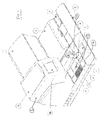
- FIG 1 shows a histology tissue embedding system incorporating aspects of the present invention.
- the system consists generally of a heated module (shown in Figure 1 ) and a cold module (shown attached to the heated module in Figure 2 ).
- the function of the heated module is primarily to dispense a tissue embedding medium (in this case paraffin wax, but other suitable media may be used) into tissue moulds and to provide storage for the various items used.
- a tissue embedding medium in this case paraffin wax, but other suitable media may be used
- the primary function of the cold module is to cool the tissue moulds after dispensing so that the wax sets.
- the tissue embedding apparatus shown in Figure 1 includes a tank 1 for the wax.
- the tank 1 is heated by suitable heating means (not shown) in order to raise the temperature of the wax so that it is in liquid form for dispensing. Wax is added to the tank via lid 1a.
- the apparatus includes a base mould storage compartment 2 for storing the base moulds into which wax will be poured, and a tissue storage tank 3 for storing tissue samples in the respective cassettes. There is also a cassette lid storage dish 4 located adjacent the tissue storage tank 3.
- liquid wax is dispensed from the wax tank 1 via an outlet valve, which includes nozzle 9a.
- the rate of dispensing of the nozzle is controlled by a wax dispense flow control 9 and the operation of the nozzle is controlled by a trigger means, which in this example is a dispense lever 8.
- a trigger means which in this example is a dispense lever 8.
- the dispense lever 8 When the dispense lever 8 is in its rest position, the nozzle is closed and no wax is dispensed. However, when the wax dispense lever is pressed by the operator away from the nozzle 9a (i.e. towards the tank 1), the nozzle is opened and wax is dispensed in accordance with the setting of the wax dispense flow control 9.
- a base mould will be held underneath the nozzle 9a, on top of a hot spot plate 6.
- the hot spot plate is heated by further heating means (not shown) which helps to prevent the wax from solidifying too quickly once it has been dispensed into the base mould.
- a cold spot plate 7 Adjacent the hot spot plate 6 is a cold spot plate 7, which is cooled by cooling means (not shown). After wax has been dispensed into the base mould, the base mould may be placed by the operator on cold spot plate 7 to increase the rate of solidification of the wax. Once the wax has substantially solidified, excess wax may be removed by the operator using wax trimmer 11.
- dashed line 12 i.e. incorporates the wax trimmer 11, the hot spot plate 6, the cold spot plate 7, and other areas for the placement of cassettes etc.
- forceps block 10 for storage of the operator's forceps.
- FIG 2 shows the apparatus of Figure 1 with the addition of a cold module, identified generally with reference numeral 20.
- the cold module incorporates a large cold plate 21, which is useable to cool a number of base moulds.
- the cold module incorporates a storage drawer 22 for further equipment storage.
- the apparatus is controlled by a control system (not shown) and the user-operable functions are accessed by means of a touch screen 14.
- Figures 3 to 5 show three different options.
- Figure 3 moulds and cassettes will be taken from the centrally located storage areas, processed by filling with wax on the left of the equipment, and then moved to the right-most end for the cold storage module.
- An alternative is shown in Figure 4 , where the cold storage module is located on the left hand side of the paraffin wax dispensing part of the apparatus.
- Figure 5 shows the apparatus includes an additional cold storage module, for further capacity.
- Figures 6 to 8 illustrate generally the filling of a mould with wax.
- Figure 6 shows a base mould 30 into which some wax 32 is placed.
- the tissue specimen 34 is placed on top of the lower layer of wax 32 and the base mould is moved on to the cold spot plate, typically until the wax becomes translucent.
- the tissue cassette 36 is placed into the base mould 30, on top of the sample 34 and the cassette is filled with wax via the nozzle 9a as shown in Figure 7 .
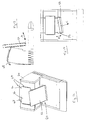
- Figure 8 shows a cross-sectional view through the portion of equipment including the wax tank and nozzle dispensing system.
- lever 8 Users will actuate the lever 8 by a variety of means e.g. finger, forceps, embedding mould. They may also be working with different size cassettes and moulds. Adjustment of the distance from the lever to the nozzle allows the user to set the distance optimally to suit their needs.
- means e.g. finger, forceps, embedding mould. They may also be working with different size cassettes and moulds. Adjustment of the distance from the lever to the nozzle allows the user to set the distance optimally to suit their needs.
- the lever position is fixed relative to the nozzle.
- a knob 38 behind the lever is used to release it, which is then adjusted before locking in position.
- the lever assembly 39 is mounted on a slideway 37 to allow the adjustment. Different locking methods could be used and/or with one or more pre-defined positions.
Landscapes
- Life Sciences & Earth Sciences (AREA)
- Health & Medical Sciences (AREA)
- General Health & Medical Sciences (AREA)
- Chemical & Material Sciences (AREA)
- Analytical Chemistry (AREA)
- Biochemistry (AREA)
- Physics & Mathematics (AREA)
- General Physics & Mathematics (AREA)
- Immunology (AREA)
- Pathology (AREA)
- Engineering & Computer Science (AREA)
- Biomedical Technology (AREA)
- Molecular Biology (AREA)
- Sampling And Sample Adjustment (AREA)
Description
- The present invention relates to an apparatus for embedding tissue samples, typically for histological or histopathological examination.
- When tissue samples are collected, it is common to fix the samples for more convenient analysis e.g. viewing under a microscope. One method of fixing is by freezing using a cryostat. An alternative is to treat the tissue samples with various fluids and then to embed each sample in a block of paraffin wax. The embedding process includes several steps, such as heating the paraffin wax, placing it and the tissue sample in a suitable container and setting the wax. Laboratory equipment known as an "embedding centre" is typically used to carry out these processes and the present invention is primarily concerned with providing an embedding centre incorporating one or more improvements.
- A tissue embedding centre will generally include a reservoir for the molten paraffin wax and a nozzle connected to the reservoir through which the molten wax can be dispensed into a mould. It is known to include a trigger in the form of a paddle adjacent to the nozzle for control of the wax through the nozzle. Typically, the paddle will be located behind the nozzle (i.e. on the opposite side to the equipment operator) and pressure on the paddle to push it away from the nozzle will operate the nozzle so as to dispense the wax. The paddle is biased to return to a rest position i.e. if there is no operator pressure on it then it returns to the rest position, in which the nozzle is controlled to be closed.
- Different equipment operators will use the paddle in different ways e.g. some will operate it by pressing on it with the tissue cassette and others by pressing on it with one of their hands. This can mean that the embedding centre equipment is easier to use for some operators than others. Generally, the aim of the present invention is to provide an adjustable paddle i.e. a paddle (or other wax dispenser control mechanism) whose rest position relative to the nozzle (or other wax dispensing outlet) is adjustable.
- Accordingly, in a first aspect, the present invention provides a histology tissue embedding apparatus according to claim 1.
- Preferably the embedding apparatus will include heating means which are usable to heat the reservoir so as to maintain the embedding medium (e.g. paraffin wax) in a molten, liquid, state and the reservoir will be heated so as to be usable. Preferably the outlet valve is a nozzle, which may be oriented substantially vertically so as to dispense the embedding medium into a mould held beneath the nozzle.
- Preferably the trigger means is a paddle, which may be located substantially behind the nozzle (from the equipment operator's perspective) as described above. The rest position of the trigger means is adjustable in a direction away from the outlet valve e.g. so as to create more space between the trigger and the outlet valve.
- A portion of the trigger means is slidably attached to a body of the embedding apparatus. The trigger means also includes a locking means (e.g. a locking screw) to retain it so that it is not slidable under normal user operation of the trigger when the locking means is locked, but when the locking means is unlocked the trigger is slidable so as to adjust its position.
- Embodiments of the invention may incorporate any one or some or all of the above aspects, together with any one or some or all of the features described below. Embodiments of the present invention will now be described with reference to the accompanying drawings in which:
-
Figure 1 is a perspective view of a histology tissue embedding centre incorporating aspects of the present invention. -
Figure 2 shows the apparatus ofFigure 1 further including a cold module according to the present invention. -
Figures 3-5 show variations on the apparatus ofFigures 1 and2 to illustrate how the apparatus may be used in practice. -
Figure 6 shows a tissue cassette and mould for use with the present invention. -
Figure 7 shows the operation of an embodiment of the tissue embedding medium dispenser according to the present invention. -
Figure 8 is a cross-sectional view through a part of an embodiment of the present invention to illustrate the tissue embedding medium dispenser. -
Figures 9 and 10 illustrates examples of the invention incorporating an embedding medium drainage module. -
Figure 11 shows the operation of the embedding medium drainage module ofFigure 10 . -
Figures 12-14 show views of further examples of a document holder, in this example mounted on a cold module. -
Figure 1 shows a histology tissue embedding system incorporating aspects of the present invention. The system consists generally of a heated module (shown inFigure 1 ) and a cold module (shown attached to the heated module inFigure 2 ). - The function of the heated module is primarily to dispense a tissue embedding medium (in this case paraffin wax, but other suitable media may be used) into tissue moulds and to provide storage for the various items used. The primary function of the cold module is to cool the tissue moulds after dispensing so that the wax sets.
- The tissue embedding apparatus shown in
Figure 1 includes a tank 1 for the wax. The tank 1 is heated by suitable heating means (not shown) in order to raise the temperature of the wax so that it is in liquid form for dispensing. Wax is added to the tank via lid 1a. The apparatus includes a base mould storage compartment 2 for storing the base moulds into which wax will be poured, and atissue storage tank 3 for storing tissue samples in the respective cassettes. There is also a cassette lid storage dish 4 located adjacent thetissue storage tank 3. - In use, liquid wax is dispensed from the wax tank 1 via an outlet valve, which includes nozzle 9a. The rate of dispensing of the nozzle is controlled by a wax
dispense flow control 9 and the operation of the nozzle is controlled by a trigger means, which in this example is adispense lever 8. When thedispense lever 8 is in its rest position, the nozzle is closed and no wax is dispensed. However, when the wax dispense lever is pressed by the operator away from the nozzle 9a (i.e. towards the tank 1), the nozzle is opened and wax is dispensed in accordance with the setting of the waxdispense flow control 9. - In use, a base mould will be held underneath the nozzle 9a, on top of a hot spot plate 6. The hot spot plate is heated by further heating means (not shown) which helps to prevent the wax from solidifying too quickly once it has been dispensed into the base mould.
- Adjacent the hot spot plate 6 is a cold spot plate 7, which is cooled by cooling means (not shown). After wax has been dispensed into the base mould, the base mould may be placed by the operator on cold spot plate 7 to increase the rate of solidification of the wax. Once the wax has substantially solidified, excess wax may be removed by the operator using wax trimmer 11.
- The general working area of the equipment, for use by the operator, is enclosed by
dashed line 12 i.e. incorporates the wax trimmer 11, the hot spot plate 6, the cold spot plate 7, and other areas for the placement of cassettes etc. In addition, there is aforceps block 10 for storage of the operator's forceps. - Waste wax accidentally dropped onto the
working area 12, and other areas, is collected via a series of grooves and channels in the working area (one example is identified with numeral 13) and is collected in awaste wax tray 5 which will be described in more detail later. -
Figure 2 shows the apparatus ofFigure 1 with the addition of a cold module, identified generally withreference numeral 20. The cold module incorporates a largecold plate 21, which is useable to cool a number of base moulds. In addition the cold module incorporates astorage drawer 22 for further equipment storage. - The apparatus is controlled by a control system (not shown) and the user-operable functions are accessed by means of a
touch screen 14. - In use, the apparatus may be operated in various ways, depending on user preference.
Figures 3 to 5 show three different options. InFigure 3 , moulds and cassettes will be taken from the centrally located storage areas, processed by filling with wax on the left of the equipment, and then moved to the right-most end for the cold storage module. An alternative is shown inFigure 4 , where the cold storage module is located on the left hand side of the paraffin wax dispensing part of the apparatus. A further option is shown inFigure 5 , where the apparatus includes an additional cold storage module, for further capacity. -
Figures 6 to 8 illustrate generally the filling of a mould with wax.Figure 6 shows abase mould 30 into which somewax 32 is placed. Thetissue specimen 34 is placed on top of the lower layer ofwax 32 and the base mould is moved on to the cold spot plate, typically until the wax becomes translucent. Following that, thetissue cassette 36 is placed into thebase mould 30, on top of thesample 34 and the cassette is filled with wax via the nozzle 9a as shown inFigure 7 . - As previously described, the operation of nozzle 9a is controlled via dispense
lever 8.Figure 8 shows a cross-sectional view through the portion of equipment including the wax tank and nozzle dispensing system. - Users will actuate the
lever 8 by a variety of means e.g. finger, forceps, embedding mould. They may also be working with different size cassettes and moulds. Adjustment of the distance from the lever to the nozzle allows the user to set the distance optimally to suit their needs. - Traditionally, the lever position is fixed relative to the nozzle.
- A
knob 38 behind the lever is used to release it, which is then adjusted before locking in position. The lever assembly 39 is mounted on aslideway 37 to allow the adjustment. Different locking methods could be used and/or with one or more pre-defined positions. - When used in this specification and claims, the terms "comprises" and "comprising" and variations thereof mean that the specified features, steps or integers are included. The terms are not to be interpreted to exclude the presence of other features, steps or components.
- The features disclosed in the foregoing description, or in the following claims, or in the accompanying drawings, expressed in their specific forms or in terms of a means for performing the disclosed function, or a method or process for obtaining the disclosed results, as appropriate, may, separately, or in any combination of such features, be utilised for realising the invention in diverse forms thereof.
Claims (3)
- A histology tissue embedding apparatus including a reservoir for an embedding medium (1) and an outlet valve (9a) connected to the reservoir (1) through which the embedding medium is dispensable, and including trigger means (8) which control the operation of the outlet valve (9a), the trigger means (8) having a rest position in which the outlet valve (9a) is closed, wherein the rest position of the trigger means (8) in relation to the outlet valve (9a) is adjustable, characterized in that a portion of the trigger means (8) is slidably attached to a body of the embedding apparatus and the trigger means (8) also includes a locking means (38) to retain it so that it is not slidable under normal user operation of the trigger means (8) when the locking means (38) is locked, but when the locking means (38) is unlocked the trigger means (8) is slidable so as to adjust its position.
- An apparatus according to Claim 1, wherein the rest position of the trigger means (8) is adjustable in a direction away from the outlet valve (9a).
- An apparatus according to Claim 1, wherein the outlet valve (9a) is a nozzle and the trigger means (8) is a paddle, located substantially behind the nozzle from the equipment operator's perspective.
Priority Applications (1)
| Application Number | Priority Date | Filing Date | Title |
|---|---|---|---|
| EP14194110.4A EP2860509B1 (en) | 2009-09-25 | 2010-09-23 | Apparatus for embedding tissue samples |
Applications Claiming Priority (1)
| Application Number | Priority Date | Filing Date | Title |
|---|---|---|---|
| GBGB0916919.4A GB0916919D0 (en) | 2009-09-25 | 2009-09-25 | Apparatus for embedding tissue samples |
Related Child Applications (2)
| Application Number | Title | Priority Date | Filing Date |
|---|---|---|---|
| EP14194110.4A Division EP2860509B1 (en) | 2009-09-25 | 2010-09-23 | Apparatus for embedding tissue samples |
| EP14194110.4A Division-Into EP2860509B1 (en) | 2009-09-25 | 2010-09-23 | Apparatus for embedding tissue samples |
Publications (3)
| Publication Number | Publication Date |
|---|---|
| EP2302350A2 EP2302350A2 (en) | 2011-03-30 |
| EP2302350A3 EP2302350A3 (en) | 2014-05-21 |
| EP2302350B1 true EP2302350B1 (en) | 2016-06-29 |
Family
ID=41350428
Family Applications (2)
| Application Number | Title | Priority Date | Filing Date |
|---|---|---|---|
| EP14194110.4A Active EP2860509B1 (en) | 2009-09-25 | 2010-09-23 | Apparatus for embedding tissue samples |
| EP10178822.2A Active EP2302350B1 (en) | 2009-09-25 | 2010-09-23 | Apparatus for embedding tissue samples |
Family Applications Before (1)
| Application Number | Title | Priority Date | Filing Date |
|---|---|---|---|
| EP14194110.4A Active EP2860509B1 (en) | 2009-09-25 | 2010-09-23 | Apparatus for embedding tissue samples |
Country Status (4)
| Country | Link |
|---|---|
| US (5) | US8486351B2 (en) |
| EP (2) | EP2860509B1 (en) |
| CN (1) | CN102169064B (en) |
| GB (2) | GB0916919D0 (en) |
Families Citing this family (18)
| Publication number | Priority date | Publication date | Assignee | Title |
|---|---|---|---|---|
| KR101279791B1 (en) | 2011-12-12 | 2013-06-28 | 유니트마 주식회사 | paraffin block trimmer |
| CN104583754A (en) | 2012-06-22 | 2015-04-29 | 莱卡生物系统努斯洛赫有限责任公司 | Tissue sample container and methods |
| WO2013192606A1 (en) | 2012-06-22 | 2013-12-27 | Leica Biosystems Nussloch Gmbh | Biopsy tissue sample transport device and method of using thereof |
| US9052256B2 (en) | 2013-03-15 | 2015-06-09 | Leica Biosystems Nussloch Gmbh | Method for processing and embedding tissue |
| US9389154B2 (en) | 2013-03-15 | 2016-07-12 | Leica Biosystems Nussloch Gmbh | Tissue cassette with biasing element |
| CA2845830C (en) | 2013-03-15 | 2020-10-27 | Leica Biosystems Nussloch Gmbh | Tissue cassette with retractable member |
| CN204330461U (en) * | 2014-12-29 | 2015-05-13 | 徕卡显微系统(上海)有限公司 | Embedding machine |
| CN105806685B (en) * | 2014-12-29 | 2020-05-05 | 徕卡显微系统(上海)有限公司 | Embedding machine with movable distributor |
| JP1556195S (en) * | 2015-07-16 | 2016-08-15 | ||
| USD810316S1 (en) * | 2015-07-16 | 2018-02-13 | Leica Biosystems Nussloch Gmbh | Embedder |
| CN107192597B (en) * | 2016-03-15 | 2021-08-27 | 徕卡显微系统(上海)有限公司 | Paraffin distributor, embedding machine and control method and device of paraffin distributor |
| JP6850625B2 (en) * | 2017-02-15 | 2021-03-31 | サクラ精機株式会社 | Embedding device |
| CN108663263A (en) * | 2017-03-31 | 2018-10-16 | 徕卡显微系统(上海)有限公司 | Device, method and the embedding machine of paraffin are distributed for controlling paraffin distributor |
| JP6511172B1 (en) * | 2018-02-01 | 2019-05-15 | サクラ精機株式会社 | Embedding device |
| JP6542924B1 (en) * | 2018-02-01 | 2019-07-10 | サクラ精機株式会社 | Wrist rest and wrist rest cushion |
| JP6944420B2 (en) | 2018-07-25 | 2021-10-06 | サクラ精機株式会社 | Embedding device |
| USD1126418S1 (en) * | 2023-02-02 | 2026-05-12 | Leica Mikrosysteme Gmbh | Microtome |
| USD1114287S1 (en) * | 2023-02-02 | 2026-02-17 | Leica Mikrosysteme Gmbh | Microtome |
Family Cites Families (11)
| Publication number | Priority date | Publication date | Assignee | Title |
|---|---|---|---|---|
| US4135883A (en) * | 1977-08-29 | 1979-01-23 | Bio-Dynamics Inc. | Blood analyzer system |
| US5480037A (en) * | 1992-06-12 | 1996-01-02 | Pope; Kip R. | Note paper holder and method |
| US20020042147A1 (en) * | 2000-09-13 | 2002-04-11 | Ross Jeffrey Allan | Method and device for preventing chatter in histological samples |
| DE10223304B4 (en) * | 2002-05-24 | 2018-12-13 | Leica Biosystems Nussloch Gmbh | Device for embedding samples in paraffin |
| US20040052408A1 (en) * | 2002-09-17 | 2004-03-18 | Paul Sharman | Method and apparatus for electronically extracting information |
| DK1552266T3 (en) * | 2002-09-26 | 2016-02-08 | Biopath Automation Llc | Apparatus and methods for automatic handling and embedding of tissue samples |
| EP1673608A4 (en) * | 2003-09-29 | 2008-05-07 | Vision Biosystems Ltd | System and method for histological tissue specimen processing |
| DE202004006265U1 (en) * | 2004-04-21 | 2004-06-17 | Leica Microsystems Nussloch Gmbh | Microtem for the production of thin sections |
| DE102008025787B3 (en) | 2008-05-29 | 2010-02-11 | Hirt Zerspanungstechnik Gmbh | Device for removing excess embedding medium |
| CN201229271Y (en) | 2008-06-05 | 2009-04-29 | 张简庆宾 | Pathological tissue observation section processor |
| GB2480782B (en) * | 2009-09-25 | 2012-05-09 | Thermo Shandon Ltd | Apparatus for embedding tissue samples |
-
2009
- 2009-09-25 GB GBGB0916919.4A patent/GB0916919D0/en not_active Ceased
-
2010
- 2010-09-23 EP EP14194110.4A patent/EP2860509B1/en active Active
- 2010-09-23 EP EP10178822.2A patent/EP2302350B1/en active Active
- 2010-09-24 GB GB1016159.4A patent/GB2473959B/en not_active Expired - Fee Related
- 2010-09-24 US US12/889,843 patent/US8486351B2/en active Active
- 2010-09-25 CN CN201010602630.8A patent/CN102169064B/en active Active
-
2013
- 2013-03-18 US US13/845,633 patent/US20130217100A1/en not_active Abandoned
- 2013-03-18 US US13/845,589 patent/US20130230905A1/en not_active Abandoned
- 2013-03-18 US US13/845,665 patent/US8715594B2/en active Active
- 2013-03-18 US US13/845,688 patent/US20130217101A1/en not_active Abandoned
Also Published As
| Publication number | Publication date |
|---|---|
| GB2473959A (en) | 2011-03-30 |
| US8715594B2 (en) | 2014-05-06 |
| EP2860509A1 (en) | 2015-04-15 |
| US20130217109A1 (en) | 2013-08-22 |
| GB2473959B (en) | 2014-08-27 |
| US20110076753A1 (en) | 2011-03-31 |
| US8486351B2 (en) | 2013-07-16 |
| US20130217100A1 (en) | 2013-08-22 |
| US20130217101A1 (en) | 2013-08-22 |
| CN102169064A (en) | 2011-08-31 |
| CN102169064B (en) | 2014-09-10 |
| GB201016159D0 (en) | 2010-11-10 |
| EP2302350A3 (en) | 2014-05-21 |
| EP2860509B1 (en) | 2021-06-09 |
| US20130230905A1 (en) | 2013-09-05 |
| EP2302350A2 (en) | 2011-03-30 |
| GB0916919D0 (en) | 2009-11-11 |
Similar Documents
| Publication | Publication Date | Title |
|---|---|---|
| EP2860509B1 (en) | Apparatus for embedding tissue samples | |
| GB2538121A (en) | Embedder | |
| US20160073819A1 (en) | Hot and Cold Beverage Maker and Method of Use | |
| CN110869734B (en) | Device for processing tissue samples and in particular for producing wax blocks containing tissue samples | |
| WO2013017829A1 (en) | Ecological and ergonomic kettle | |
| WO1988002851A2 (en) | Refrigerated chamber for obtaining thin slices at low temperature | |
| AU2024203867A1 (en) | Fine tank pressure control using thermal energy for preparing cytological specimens from patient samples | |
| GB2480781A (en) | Histology tissue embedding apparatus with trimming means | |
| CN105806685B (en) | Embedding machine with movable distributor | |
| EP0172728A2 (en) | A device for the cryogenic transfer of specimens | |
| CN109906368A (en) | Embedding device | |
| EP2797468B1 (en) | A hot beverage preparation machine | |
| EP0654009B1 (en) | Drink-dispensing device | |
| JP6944420B2 (en) | Embedding device | |
| Jorgensen et al. | HuBMAP: Paraffin Embedding Tissue Samples | |
| EP2077085A1 (en) | Improvements in and relating to water heating apparatus | |
| HK40015426B (en) | Fine tank pressure control using thermal energy for preparing cytological specimens from patient samples | |
| CA2509031A1 (en) | Method for constructing array blocks, and tissue punching instrument and tissue blocks used therefor |
Legal Events
| Date | Code | Title | Description |
|---|---|---|---|
| PUAI | Public reference made under article 153(3) epc to a published international application that has entered the european phase |
Free format text: ORIGINAL CODE: 0009012 |
|
| AK | Designated contracting states |
Kind code of ref document: A2 Designated state(s): AL AT BE BG CH CY CZ DE DK EE ES FI FR GB GR HR HU IE IS IT LI LT LU LV MC MK MT NL NO PL PT RO SE SI SK SM TR |
|
| AX | Request for extension of the european patent |
Extension state: BA ME RS |
|
| PUAL | Search report despatched |
Free format text: ORIGINAL CODE: 0009013 |
|
| AK | Designated contracting states |
Kind code of ref document: A3 Designated state(s): AL AT BE BG CH CY CZ DE DK EE ES FI FR GB GR HR HU IE IS IT LI LT LU LV MC MK MT NL NO PL PT RO SE SI SK SM TR |
|
| AX | Request for extension of the european patent |
Extension state: BA ME RS |
|
| RIC1 | Information provided on ipc code assigned before grant |
Ipc: G01N 1/36 20060101AFI20140416BHEP |
|
| 17P | Request for examination filed |
Effective date: 20141111 |
|
| RBV | Designated contracting states (corrected) |
Designated state(s): AL AT BE BG CH CY CZ DE DK EE ES FI FR GB GR HR HU IE IS IT LI LT LU LV MC MK MT NL NO PL PT RO SE SI SK SM TR |
|
| GRAP | Despatch of communication of intention to grant a patent |
Free format text: ORIGINAL CODE: EPIDOSNIGR1 |
|
| INTG | Intention to grant announced |
Effective date: 20160114 |
|
| GRAS | Grant fee paid |
Free format text: ORIGINAL CODE: EPIDOSNIGR3 |
|
| GRAA | (expected) grant |
Free format text: ORIGINAL CODE: 0009210 |
|
| AK | Designated contracting states |
Kind code of ref document: B1 Designated state(s): AL AT BE BG CH CY CZ DE DK EE ES FI FR GB GR HR HU IE IS IT LI LT LU LV MC MK MT NL NO PL PT RO SE SI SK SM TR |
|
| REG | Reference to a national code |
Ref country code: GB Ref legal event code: FG4D |
|
| REG | Reference to a national code |
Ref country code: CH Ref legal event code: EP |
|
| REG | Reference to a national code |
Ref country code: AT Ref legal event code: REF Ref document number: 809490 Country of ref document: AT Kind code of ref document: T Effective date: 20160715 |
|
| REG | Reference to a national code |
Ref country code: IE Ref legal event code: FG4D |
|
| REG | Reference to a national code |
Ref country code: DE Ref legal event code: R096 Ref document number: 602010034257 Country of ref document: DE |
|
| REG | Reference to a national code |
Ref country code: FR Ref legal event code: PLFP Year of fee payment: 7 |
|
| REG | Reference to a national code |
Ref country code: LT Ref legal event code: MG4D |
|
| PG25 | Lapsed in a contracting state [announced via postgrant information from national office to epo] |
Ref country code: LT Free format text: LAPSE BECAUSE OF FAILURE TO SUBMIT A TRANSLATION OF THE DESCRIPTION OR TO PAY THE FEE WITHIN THE PRESCRIBED TIME-LIMIT Effective date: 20160629 Ref country code: FI Free format text: LAPSE BECAUSE OF FAILURE TO SUBMIT A TRANSLATION OF THE DESCRIPTION OR TO PAY THE FEE WITHIN THE PRESCRIBED TIME-LIMIT Effective date: 20160629 Ref country code: NO Free format text: LAPSE BECAUSE OF FAILURE TO SUBMIT A TRANSLATION OF THE DESCRIPTION OR TO PAY THE FEE WITHIN THE PRESCRIBED TIME-LIMIT Effective date: 20160929 |
|
| REG | Reference to a national code |
Ref country code: NL Ref legal event code: MP Effective date: 20160629 |
|
| PG25 | Lapsed in a contracting state [announced via postgrant information from national office to epo] |
Ref country code: HR Free format text: LAPSE BECAUSE OF FAILURE TO SUBMIT A TRANSLATION OF THE DESCRIPTION OR TO PAY THE FEE WITHIN THE PRESCRIBED TIME-LIMIT Effective date: 20160629 Ref country code: LV Free format text: LAPSE BECAUSE OF FAILURE TO SUBMIT A TRANSLATION OF THE DESCRIPTION OR TO PAY THE FEE WITHIN THE PRESCRIBED TIME-LIMIT Effective date: 20160629 Ref country code: SE Free format text: LAPSE BECAUSE OF FAILURE TO SUBMIT A TRANSLATION OF THE DESCRIPTION OR TO PAY THE FEE WITHIN THE PRESCRIBED TIME-LIMIT Effective date: 20160629 Ref country code: NL Free format text: LAPSE BECAUSE OF FAILURE TO SUBMIT A TRANSLATION OF THE DESCRIPTION OR TO PAY THE FEE WITHIN THE PRESCRIBED TIME-LIMIT Effective date: 20160629 Ref country code: GR Free format text: LAPSE BECAUSE OF FAILURE TO SUBMIT A TRANSLATION OF THE DESCRIPTION OR TO PAY THE FEE WITHIN THE PRESCRIBED TIME-LIMIT Effective date: 20160930 |
|
| REG | Reference to a national code |
Ref country code: AT Ref legal event code: MK05 Ref document number: 809490 Country of ref document: AT Kind code of ref document: T Effective date: 20160629 |
|
| PG25 | Lapsed in a contracting state [announced via postgrant information from national office to epo] |
Ref country code: RO Free format text: LAPSE BECAUSE OF FAILURE TO SUBMIT A TRANSLATION OF THE DESCRIPTION OR TO PAY THE FEE WITHIN THE PRESCRIBED TIME-LIMIT Effective date: 20160629 Ref country code: EE Free format text: LAPSE BECAUSE OF FAILURE TO SUBMIT A TRANSLATION OF THE DESCRIPTION OR TO PAY THE FEE WITHIN THE PRESCRIBED TIME-LIMIT Effective date: 20160629 Ref country code: IS Free format text: LAPSE BECAUSE OF FAILURE TO SUBMIT A TRANSLATION OF THE DESCRIPTION OR TO PAY THE FEE WITHIN THE PRESCRIBED TIME-LIMIT Effective date: 20161029 Ref country code: IT Free format text: LAPSE BECAUSE OF FAILURE TO SUBMIT A TRANSLATION OF THE DESCRIPTION OR TO PAY THE FEE WITHIN THE PRESCRIBED TIME-LIMIT Effective date: 20160629 Ref country code: SK Free format text: LAPSE BECAUSE OF FAILURE TO SUBMIT A TRANSLATION OF THE DESCRIPTION OR TO PAY THE FEE WITHIN THE PRESCRIBED TIME-LIMIT Effective date: 20160629 Ref country code: CZ Free format text: LAPSE BECAUSE OF FAILURE TO SUBMIT A TRANSLATION OF THE DESCRIPTION OR TO PAY THE FEE WITHIN THE PRESCRIBED TIME-LIMIT Effective date: 20160629 |
|
| PG25 | Lapsed in a contracting state [announced via postgrant information from national office to epo] |
Ref country code: ES Free format text: LAPSE BECAUSE OF FAILURE TO SUBMIT A TRANSLATION OF THE DESCRIPTION OR TO PAY THE FEE WITHIN THE PRESCRIBED TIME-LIMIT Effective date: 20160629 Ref country code: PL Free format text: LAPSE BECAUSE OF FAILURE TO SUBMIT A TRANSLATION OF THE DESCRIPTION OR TO PAY THE FEE WITHIN THE PRESCRIBED TIME-LIMIT Effective date: 20160629 Ref country code: PT Free format text: LAPSE BECAUSE OF FAILURE TO SUBMIT A TRANSLATION OF THE DESCRIPTION OR TO PAY THE FEE WITHIN THE PRESCRIBED TIME-LIMIT Effective date: 20161031 Ref country code: SM Free format text: LAPSE BECAUSE OF FAILURE TO SUBMIT A TRANSLATION OF THE DESCRIPTION OR TO PAY THE FEE WITHIN THE PRESCRIBED TIME-LIMIT Effective date: 20160629 Ref country code: BE Free format text: LAPSE BECAUSE OF NON-PAYMENT OF DUE FEES Effective date: 20160629 Ref country code: AT Free format text: LAPSE BECAUSE OF FAILURE TO SUBMIT A TRANSLATION OF THE DESCRIPTION OR TO PAY THE FEE WITHIN THE PRESCRIBED TIME-LIMIT Effective date: 20160629 |
|
| REG | Reference to a national code |
Ref country code: DE Ref legal event code: R097 Ref document number: 602010034257 Country of ref document: DE |
|
| PG25 | Lapsed in a contracting state [announced via postgrant information from national office to epo] |
Ref country code: MC Free format text: LAPSE BECAUSE OF FAILURE TO SUBMIT A TRANSLATION OF THE DESCRIPTION OR TO PAY THE FEE WITHIN THE PRESCRIBED TIME-LIMIT Effective date: 20160629 |
|
| REG | Reference to a national code |
Ref country code: CH Ref legal event code: PL |
|
| PLBE | No opposition filed within time limit |
Free format text: ORIGINAL CODE: 0009261 |
|
| STAA | Information on the status of an ep patent application or granted ep patent |
Free format text: STATUS: NO OPPOSITION FILED WITHIN TIME LIMIT |
|
| PG25 | Lapsed in a contracting state [announced via postgrant information from national office to epo] |
Ref country code: DK Free format text: LAPSE BECAUSE OF FAILURE TO SUBMIT A TRANSLATION OF THE DESCRIPTION OR TO PAY THE FEE WITHIN THE PRESCRIBED TIME-LIMIT Effective date: 20160629 |
|
| 26N | No opposition filed |
Effective date: 20170330 |
|
| REG | Reference to a national code |
Ref country code: IE Ref legal event code: MM4A |
|
| PG25 | Lapsed in a contracting state [announced via postgrant information from national office to epo] |
Ref country code: CH Free format text: LAPSE BECAUSE OF NON-PAYMENT OF DUE FEES Effective date: 20160930 Ref country code: LI Free format text: LAPSE BECAUSE OF NON-PAYMENT OF DUE FEES Effective date: 20160930 Ref country code: IE Free format text: LAPSE BECAUSE OF NON-PAYMENT OF DUE FEES Effective date: 20160923 |
|
| REG | Reference to a national code |
Ref country code: FR Ref legal event code: PLFP Year of fee payment: 8 |
|
| PG25 | Lapsed in a contracting state [announced via postgrant information from national office to epo] |
Ref country code: SI Free format text: LAPSE BECAUSE OF FAILURE TO SUBMIT A TRANSLATION OF THE DESCRIPTION OR TO PAY THE FEE WITHIN THE PRESCRIBED TIME-LIMIT Effective date: 20160629 Ref country code: LU Free format text: LAPSE BECAUSE OF NON-PAYMENT OF DUE FEES Effective date: 20160923 Ref country code: BG Free format text: LAPSE BECAUSE OF FAILURE TO SUBMIT A TRANSLATION OF THE DESCRIPTION OR TO PAY THE FEE WITHIN THE PRESCRIBED TIME-LIMIT Effective date: 20160929 |
|
| PG25 | Lapsed in a contracting state [announced via postgrant information from national office to epo] |
Ref country code: HU Free format text: LAPSE BECAUSE OF FAILURE TO SUBMIT A TRANSLATION OF THE DESCRIPTION OR TO PAY THE FEE WITHIN THE PRESCRIBED TIME-LIMIT; INVALID AB INITIO Effective date: 20100923 Ref country code: CY Free format text: LAPSE BECAUSE OF FAILURE TO SUBMIT A TRANSLATION OF THE DESCRIPTION OR TO PAY THE FEE WITHIN THE PRESCRIBED TIME-LIMIT Effective date: 20160629 |
|
| PG25 | Lapsed in a contracting state [announced via postgrant information from national office to epo] |
Ref country code: MK Free format text: LAPSE BECAUSE OF FAILURE TO SUBMIT A TRANSLATION OF THE DESCRIPTION OR TO PAY THE FEE WITHIN THE PRESCRIBED TIME-LIMIT Effective date: 20160629 Ref country code: TR Free format text: LAPSE BECAUSE OF FAILURE TO SUBMIT A TRANSLATION OF THE DESCRIPTION OR TO PAY THE FEE WITHIN THE PRESCRIBED TIME-LIMIT Effective date: 20160629 Ref country code: MT Free format text: LAPSE BECAUSE OF NON-PAYMENT OF DUE FEES Effective date: 20160930 |
|
| REG | Reference to a national code |
Ref country code: FR Ref legal event code: PLFP Year of fee payment: 9 |
|
| PG25 | Lapsed in a contracting state [announced via postgrant information from national office to epo] |
Ref country code: AL Free format text: LAPSE BECAUSE OF FAILURE TO SUBMIT A TRANSLATION OF THE DESCRIPTION OR TO PAY THE FEE WITHIN THE PRESCRIBED TIME-LIMIT Effective date: 20160629 |
|
| REG | Reference to a national code |
Ref country code: DE Ref legal event code: R081 Ref document number: 602010034257 Country of ref document: DE Owner name: SHANDON DIAGNOSTICS LTD., RUNCORN, GB Free format text: FORMER OWNER: THERMO SHANDON LTD., RUNCORN, CHESHIRE, GB Ref country code: DE Ref legal event code: R082 Ref document number: 602010034257 Country of ref document: DE Representative=s name: MEWBURN ELLIS LLP, DE |
|
| P01 | Opt-out of the competence of the unified patent court (upc) registered |
Effective date: 20230507 |
|
| PGFP | Annual fee paid to national office [announced via postgrant information from national office to epo] |
Ref country code: DE Payment date: 20250929 Year of fee payment: 16 |
|
| PGFP | Annual fee paid to national office [announced via postgrant information from national office to epo] |
Ref country code: GB Payment date: 20250929 Year of fee payment: 16 |
|
| PGFP | Annual fee paid to national office [announced via postgrant information from national office to epo] |
Ref country code: FR Payment date: 20250925 Year of fee payment: 16 |