EP2302173A1 - Gas turbine - Google Patents
Gas turbine Download PDFInfo
- Publication number
- EP2302173A1 EP2302173A1 EP09171142A EP09171142A EP2302173A1 EP 2302173 A1 EP2302173 A1 EP 2302173A1 EP 09171142 A EP09171142 A EP 09171142A EP 09171142 A EP09171142 A EP 09171142A EP 2302173 A1 EP2302173 A1 EP 2302173A1
- Authority
- EP
- European Patent Office
- Prior art keywords
- guide vane
- gas turbine
- passages
- airfoil row
- gap
- Prior art date
- Legal status (The legal status is an assumption and is not a legal conclusion. Google has not performed a legal analysis and makes no representation as to the accuracy of the status listed.)
- Granted
Links
Images


Classifications
-
- F—MECHANICAL ENGINEERING; LIGHTING; HEATING; WEAPONS; BLASTING
- F01—MACHINES OR ENGINES IN GENERAL; ENGINE PLANTS IN GENERAL; STEAM ENGINES
- F01D—NON-POSITIVE DISPLACEMENT MACHINES OR ENGINES, e.g. STEAM TURBINES
- F01D9/00—Stators
- F01D9/02—Nozzles; Nozzle boxes; Stator blades; Guide conduits, e.g. individual nozzles
- F01D9/04—Nozzles; Nozzle boxes; Stator blades; Guide conduits, e.g. individual nozzles forming ring or sector
-
- F—MECHANICAL ENGINEERING; LIGHTING; HEATING; WEAPONS; BLASTING
- F01—MACHINES OR ENGINES IN GENERAL; ENGINE PLANTS IN GENERAL; STEAM ENGINES
- F01D—NON-POSITIVE DISPLACEMENT MACHINES OR ENGINES, e.g. STEAM TURBINES
- F01D11/00—Preventing or minimising internal leakage of working-fluid, e.g. between stages
- F01D11/005—Sealing means between non relatively rotating elements
-
- F—MECHANICAL ENGINEERING; LIGHTING; HEATING; WEAPONS; BLASTING
- F01—MACHINES OR ENGINES IN GENERAL; ENGINE PLANTS IN GENERAL; STEAM ENGINES
- F01D—NON-POSITIVE DISPLACEMENT MACHINES OR ENGINES, e.g. STEAM TURBINES
- F01D25/00—Component parts, details, or accessories, not provided for in, or of interest apart from, other groups
- F01D25/08—Cooling; Heating; Heat-insulation
- F01D25/12—Cooling
-
- F—MECHANICAL ENGINEERING; LIGHTING; HEATING; WEAPONS; BLASTING
- F01—MACHINES OR ENGINES IN GENERAL; ENGINE PLANTS IN GENERAL; STEAM ENGINES
- F01D—NON-POSITIVE DISPLACEMENT MACHINES OR ENGINES, e.g. STEAM TURBINES
- F01D5/00—Blades; Blade-carrying members; Heating, heat-insulating, cooling or antivibration means on the blades or the members
- F01D5/02—Blade-carrying members, e.g. rotors
- F01D5/08—Heating, heat-insulating or cooling means
- F01D5/081—Cooling fluid being directed on the side of the rotor disc or at the roots of the blades
-
- F—MECHANICAL ENGINEERING; LIGHTING; HEATING; WEAPONS; BLASTING
- F05—INDEXING SCHEMES RELATING TO ENGINES OR PUMPS IN VARIOUS SUBCLASSES OF CLASSES F01-F04
- F05D—INDEXING SCHEME FOR ASPECTS RELATING TO NON-POSITIVE-DISPLACEMENT MACHINES OR ENGINES, GAS-TURBINES OR JET-PROPULSION PLANTS
- F05D2240/00—Components
- F05D2240/10—Stators
-
- F—MECHANICAL ENGINEERING; LIGHTING; HEATING; WEAPONS; BLASTING
- F05—INDEXING SCHEMES RELATING TO ENGINES OR PUMPS IN VARIOUS SUBCLASSES OF CLASSES F01-F04
- F05D—INDEXING SCHEME FOR ASPECTS RELATING TO NON-POSITIVE-DISPLACEMENT MACHINES OR ENGINES, GAS-TURBINES OR JET-PROPULSION PLANTS
- F05D2240/00—Components
- F05D2240/80—Platforms for stationary or moving blades
- F05D2240/81—Cooled platforms
Definitions
- these show a gas turbine 1 comprising the combustion chamber 2 followed by the stator airfoil row 4 and the rotor airfoil row 6.
- the two contacting sides of two adjacent guide vane boxes may be provided with the slot, such that the passages 34 are defined between two facing slots.
Landscapes
- Engineering & Computer Science (AREA)
- Mechanical Engineering (AREA)
- General Engineering & Computer Science (AREA)
- Turbine Rotor Nozzle Sealing (AREA)
Abstract
Description
- The present invention relates to a gas turbine.
- In particular the present invention refers to the sealing of the zone between the guide vane boxes of the high-pressure turbine immediately downstream of the combustion chamber and a fixed frame, such that possible leakages of hot gases flowing in the combustion chamber and/or compressed air used to seal the zone between the combustion chamber and stator airfoil row do not enter the rotor airfoils cooling circuit.
- In the following reference will be made to
figure 1 for describing the relevant parts of the gas turbine; in particular reference will be made to a sequential combustion gas turbine, it is anyhow clear that the structure according to the invention may be implemented in any gas turbine also not being a sequential combustion gas turbine. - Sequential
combustion gas turbines 1 have a compressor (not shown) compressing air and supplying it to first burners (not shown) where fuel is injected and a mixture to be combusted is formed. - Downstream of the first burners a
first combustion chamber 2 is provided, where the mixture is combusted to form high pressure hot gases F that are supplied to a high-pressure expansion stage. - The high-pressure expansion stage comprises a
stator airfoil row 4 separated from thecombustion chamber 2 by afirst gap 5, and arotor airfoil row 6 separated from thestator airfoil row 4 by asecond gap 7;third gaps 8 are provided between therotor airfoil row 6 and anannular duct 9 feeding a plurality of side-by-sidesecond burners 10, wherein further fuel is injected in the hot gases (still reach in air) already partially expanded in the high-pressure expansion stage, such that an ignitable mixture is formed. This ignitable mixture is combusted in a second combustion chamber (not shown) and the hot gases produced are further expanded in a low pressure turbine (not shown). - The
stator airfoil row 4 is made ofstator airfoils 15 defining between each other guide vanes and havingendwalls 16 connected to guidevane boxes 17. - The
guide vane boxes 17 have a box structure and are fed with cooling air A via connections not shown for simplicity. - In particular, the cooling air A is air coming from the compressor at a temperature of about 450-550°C and cooled by an external cooler to a temperature of typically 200-400°C.
- Moreover the
guide vane boxes 17 are also provided withnozzles 20 that inject the cooling air A into thesecond gap 7. - The
rotor airfoil row 6 comprises a plurality ofrotor airfoils 22 having a hollow body provided with aninlet 23 arranged to collect the cooling air A injected from thenozzles 20. - During operation, the hot gases F formed in the
first combustion chamber 2 pass through the stator androtor airfoil row rotor airfoil row 6 extracts mechanical power from them. - Moreover, the air A from the
guide vane boxes 17 is injected through thenozzles 20 in thesecond gap 7 towards therotor airfoil inlets 23. - As the
rotor airfoil row 6 rotate with high speed, it draws the cooling air A injected from thenozzles 20 and makes it to enter therotor airfoil 22 via theinlets 23. - The cooling air A entering the
rotor airfoils 22 cools therotor airfoils 22 and is then injected through holes (usually at the leading edge and trailing edge of each rotor airfoil row); the air injected through the leading and trailing edges of therotor airfoils 22 is indicated by A2. - In order to prevent the hot gases F from entering the first gap 5 (the hot gases have a temperature of about 1200-1500°C and would impair the components close to the first gap 5), compressed air (the so called purge air) is diverted from the compressor and is injected in the
first gap 5. This air has a temperature of about 450-550°C and thus is not dangerous for the components close to thegaps 5. - In addition, in order to prevent the compressed air (purge air) from reaching the
rotor airfoil inlet 23,seals 25 are provided between thestator airfoil endwalls 16/guide vane boxes 17 and afixed frame 26. - Nevertheless, the compressed air diverted from the compressor may leakage and pass through the
seals 25 and mix with the cooling air A injected in thesecond gap 7. - For this reason, the cooling air A flow rate is quite large, such that, in all operating conditions, the air entering the
rotor airfoil 22 has a correct temperature to safeguard the rotor airfoil integrity and guarantee their lifetime. - Nevertheless, since the cooling air A flow rate diverted from the compressor into the guide vane boxes is quite large, efficiency of the gas turbine is reduced.
- The technical aim of the present invention is therefore to provide a gas turbine by which the said problems of the known art are eliminated.
- Within the scope of this technical aim, an object of the invention is to provide a gas turbine having an increased efficiency when compared with traditional gas turbines.
- The technical aim, together with these and further objects, are attained according to the invention by providing a gas turbine in accordance with the accompanying claims.
- Further characteristics and advantages of the invention will be more apparent from the description of a preferred but non-exclusive embodiment of the gas turbine according to the invention, illustrated by way of nonlimiting example in the accompanying drawings, in which:
-
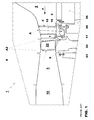
Figure 1 shows a schematic cross section of a portion of a gas turbine according to the prior art; -
Figure 2 shows a schematic cross section of a portion of a gas turbine according to the invention; and -
Figures 3 and 4 show a particular of guide vane boxes according to two embodiments of the invention. - With reference to the figures, these show a
gas turbine 1 comprising thecombustion chamber 2 followed by thestator airfoil row 4 and therotor airfoil row 6. - The structure of the gas turbine is the same as that already described; it is thus not described again and with the same reference numbers the same elements are indicated.
- In particular, the
guide vane boxes 17 are provided withpassages 30 connecting azone 31 upstream of theguide vanes boxes 17 to azone 32 of thesecond gap 7 downstream of theguide vanes boxes 17. - In addition, the
mouth 34 of thepassages 30 facing therotor airfoil row 6 is closer to ahot gases path 35 than thenozzles 20. - The
mouth 34 of thepassages 30 facing therotor airfoil row 6 is substantially as close as, or it is closer than therotor airfoil inlet 23 to thehot gases path 35. This lets the flow going out from themouth 34 not be drawn from therotor airfoil row 6 to enter theinlet 23. - In a first embodiment (
figure 4 ), thepassages 30 are defined by slots atsidewalls 36 of theguide vane boxes 17. - In this embodiment, the two contacting sides of two adjacent guide vane boxes may be provided with the slot, such that the
passages 34 are defined between two facing slots. - Alternatively only one of the two contacting
sidewalls 36 of the adjacentguide vane boxes 17 may be provided with the slot, in this case thepassages 30 are defined by the slot of aguide vane box 17 and the flat surface of the adjacentguide vane box 17. - In a different embodiment (
figure 3 ), thepassages 30 extend inside of theguide vane boxes 17 and are defined by pipes. - Naturally, in further embodiments the guide vane boxes may be provided with both the slot and the pipes.
- In addition, a
seal 37 is provided downstream of themouths 38 of thepassages 30 opposite therotor airfoil row 6, between theguide vane boxes 17 and thefixed frame 26. This lets the leakage that may overcome theseals 25 be withheld in a zone separate from therotor airfoil row 6. - The operation of the gas turbine of the invention is apparent from that described and illustrated and is substantially the following.
- The hot gases pass through the
hot gases path 35 and thus they pass through thecombustion chamber 2, thestator airfoil row 4 and therotor airfoil 6. - Through the
first gap 5 compressed air (purge air) is supplied in thecombustion chamber 2. - A part of the compressed air (purge air) may leak, overcoming the
seals 25 to enter thezone 31 upstream of theguide vane boxes 17. - Thanks to its high pressure (greater than the pressure inside of the second slot 7), the compressed air (purge air) enters the
passages 30 through themouths 38, passes through thepassages 30 and moves out through themouths 34 entering thesecond gap 7 in a zone from where it cannot enter therotor airfoil inlet 23; thus the compressed air (purge air) enters thehot gases path 35. - The
additional seal 37 keeps this compressed air (purge air) in a zone adjacent to themouth 38 of the passage and prevents the high temperature compressed air from being drawn from the high speed rotatingrotor airfoil row 6. - The gas turbine conceived in this manner is susceptible to numerous modifications and variants, all falling within the scope of the inventive concept; moreover all details can be replaced by technically equivalent elements.
- In practice the materials used and the dimensions can be chosen at will according to requirements and to the state of the art.
-
- 1
- gas turbine
- 2
- combustion chamber
- 4
- stator airfoil row
- 5
- first gap
- 6
- rotor airfoil row
- 7
- second gap
- 8
- third gap
- 9
- annular gap
- 10
- second burner
- 15
- stator airfoils
- 16
- endwalls of 15
- 17
- guide vane boxes
- 20
- nozzles
- 22
- rotor airfoils
- 23
- rotor airfoil inlet
- 25
- seals
- 26
- fixed frame
- 30
- passages
- 31
- zone upstream of the guide vane boxes
- 32
- zone downstream of the guide vane boxes
- 34
- mouth of 30
- 35
- hot gases path
- 36
- sidewalls of 17
- 37
- seal
- 38
- mouth of 30
- A
- cooling air
- A2
- air injected through 22
- F
- hot gases flow
Claims (6)
- Gas turbine (1) comprising a stator airfoil row (4) defining a plurality of guide vanes, and a rotor airfoil row (6) separated by the stator airfoil row (4) by at least a gap (7), wherein the stator airfoils (15) of the stator airfoil row (4) are connected to guide vane boxes (17) collecting a cooling fluid (A) and injecting it through nozzles (20) in said gap (7) to make it to enter rotor airfoil inlets (23), characterised in that said guide vane boxes (17) are provided with passages (30) connecting a zone (31) upstream of the guide vane boxes (17) to a zone (32) of the gap (7) downstream of the guide vane boxes (32), and in that mouths (34) of the passages (30) facing the rotor airfoil row (6) are closer to a hot gases path (35) than said nozzles (20).
- Gas turbine (1) as claimed in claim 1, characterised in that said mouth (34) of the passages (30) facing the rotor airfoil row (6) is substantially as close as, or it is closer than the rotor airfoil inlet (23) to the hot gases path (35).
- Gas turbine (1) as claimed in claim 1, characterised in that said passages (30) are defined by slots at sidewalls of the guide vane boxes (17).
- Gas turbine (1) as claimed in claim 1, characterised in that said passages (30) extend inside of guide vane boxes (17).
- Gas turbine (1) as claimed in claim 4, characterised in that said passages (30) are defined by pipes.
- Gas turbine (1) as claimed in claim 1, characterised in that a seal (37) is provided downstream of mouths (38) of the passages (30) opposite to the rotor airfoil row (6) between the guide vane boxes (17) and a fixed frame (26).
Priority Applications (3)
| Application Number | Priority Date | Filing Date | Title |
|---|---|---|---|
| EP09171142.4A EP2302173B8 (en) | 2009-09-23 | 2009-09-23 | Gas turbine |
| US12/882,409 US8979479B2 (en) | 2009-09-23 | 2010-09-15 | Gas turbine |
| JP2010212081A JP5840353B2 (en) | 2009-09-23 | 2010-09-22 | gas turbine |
Applications Claiming Priority (1)
| Application Number | Priority Date | Filing Date | Title |
|---|---|---|---|
| EP09171142.4A EP2302173B8 (en) | 2009-09-23 | 2009-09-23 | Gas turbine |
Publications (3)
| Publication Number | Publication Date |
|---|---|
| EP2302173A1 true EP2302173A1 (en) | 2011-03-30 |
| EP2302173B1 EP2302173B1 (en) | 2017-03-01 |
| EP2302173B8 EP2302173B8 (en) | 2017-08-02 |
Family
ID=41820796
Family Applications (1)
| Application Number | Title | Priority Date | Filing Date |
|---|---|---|---|
| EP09171142.4A Active EP2302173B8 (en) | 2009-09-23 | 2009-09-23 | Gas turbine |
Country Status (3)
| Country | Link |
|---|---|
| US (1) | US8979479B2 (en) |
| EP (1) | EP2302173B8 (en) |
| JP (1) | JP5840353B2 (en) |
Families Citing this family (6)
| Publication number | Priority date | Publication date | Assignee | Title |
|---|---|---|---|---|
| JP5898443B2 (en) * | 2011-03-28 | 2016-04-06 | 富士フイルム株式会社 | Cellulose acylate film, retardation film, polarizing plate and liquid crystal display device |
| US9970299B2 (en) * | 2015-09-16 | 2018-05-15 | General Electric Company | Mixing chambers for turbine wheel space cooling |
| US10132195B2 (en) | 2015-10-20 | 2018-11-20 | General Electric Company | Wheel space purge flow mixing chamber |
| US10125632B2 (en) | 2015-10-20 | 2018-11-13 | General Electric Company | Wheel space purge flow mixing chamber |
| US10519873B2 (en) | 2016-04-06 | 2019-12-31 | General Electric Company | Air bypass system for rotor shaft cooling |
| US10641174B2 (en) | 2017-01-18 | 2020-05-05 | General Electric Company | Rotor shaft cooling |
Citations (7)
| Publication number | Priority date | Publication date | Assignee | Title |
|---|---|---|---|---|
| FR1351268A (en) | 1963-03-20 | 1964-01-31 | Rolls Royce | Gas turbine engine with cooled turbine blade |
| GB2100360A (en) * | 1981-06-11 | 1982-12-22 | Gen Electric | Cooling air injector for turbine blades |
| US4666368A (en) * | 1986-05-01 | 1987-05-19 | General Electric Company | Swirl nozzle for a cooling system in gas turbine engines |
| US4882902A (en) * | 1986-04-30 | 1989-11-28 | General Electric Company | Turbine cooling air transferring apparatus |
| GB2246836A (en) | 1981-05-07 | 1992-02-12 | Rolls Royce | Fluid flow valve |
| US5135354A (en) * | 1990-09-14 | 1992-08-04 | United Technologies Corporation | Gas turbine blade and disk |
| EP0636765A1 (en) | 1993-07-15 | 1995-02-01 | Societe Nationale D'etude Et De Construction De Moteurs D'aviation "Snecma" | Cooling of turbine rotor disk |
Family Cites Families (6)
| Publication number | Priority date | Publication date | Assignee | Title |
|---|---|---|---|---|
| GB2081392B (en) * | 1980-08-06 | 1983-09-21 | Rolls Royce | Turbomachine seal |
| DE10330471A1 (en) * | 2003-07-05 | 2005-02-03 | Alstom Technology Ltd | Device for separating foreign particles from the cooling air that can be fed to the moving blades of a turbine |
| GB2426289B (en) * | 2005-04-01 | 2007-07-04 | Rolls Royce Plc | Cooling system for a gas turbine engine |
| US7189055B2 (en) * | 2005-05-31 | 2007-03-13 | Pratt & Whitney Canada Corp. | Coverplate deflectors for redirecting a fluid flow |
| US8262342B2 (en) * | 2008-07-10 | 2012-09-11 | Honeywell International Inc. | Gas turbine engine assemblies with recirculated hot gas ingestion |
| JP5134570B2 (en) | 2009-02-23 | 2013-01-30 | 三菱重工業株式会社 | Turbine cooling structure and gas turbine |
-
2009
- 2009-09-23 EP EP09171142.4A patent/EP2302173B8/en active Active
-
2010
- 2010-09-15 US US12/882,409 patent/US8979479B2/en not_active Expired - Fee Related
- 2010-09-22 JP JP2010212081A patent/JP5840353B2/en not_active Expired - Fee Related
Patent Citations (7)
| Publication number | Priority date | Publication date | Assignee | Title |
|---|---|---|---|---|
| FR1351268A (en) | 1963-03-20 | 1964-01-31 | Rolls Royce | Gas turbine engine with cooled turbine blade |
| GB2246836A (en) | 1981-05-07 | 1992-02-12 | Rolls Royce | Fluid flow valve |
| GB2100360A (en) * | 1981-06-11 | 1982-12-22 | Gen Electric | Cooling air injector for turbine blades |
| US4882902A (en) * | 1986-04-30 | 1989-11-28 | General Electric Company | Turbine cooling air transferring apparatus |
| US4666368A (en) * | 1986-05-01 | 1987-05-19 | General Electric Company | Swirl nozzle for a cooling system in gas turbine engines |
| US5135354A (en) * | 1990-09-14 | 1992-08-04 | United Technologies Corporation | Gas turbine blade and disk |
| EP0636765A1 (en) | 1993-07-15 | 1995-02-01 | Societe Nationale D'etude Et De Construction De Moteurs D'aviation "Snecma" | Cooling of turbine rotor disk |
Also Published As
| Publication number | Publication date |
|---|---|
| EP2302173B1 (en) | 2017-03-01 |
| JP2011069366A (en) | 2011-04-07 |
| US8979479B2 (en) | 2015-03-17 |
| US20110070077A1 (en) | 2011-03-24 |
| JP5840353B2 (en) | 2016-01-06 |
| EP2302173B8 (en) | 2017-08-02 |
Similar Documents
| Publication | Publication Date | Title |
|---|---|---|
| US9011079B2 (en) | Turbine nozzle compartmentalized cooling system | |
| US8783044B2 (en) | Turbine stator nozzle cooling structure | |
| US9458767B2 (en) | Fuel injection insert for a turbine nozzle segment | |
| US20100189542A1 (en) | Turbine arrangement and method of cooling a shroud located at the tip of a turbine blade | |
| US10753615B2 (en) | Dual fuel concentric nozzle for a gas turbine | |
| US20140260318A1 (en) | Side seal slot for a combustion liner | |
| EP2302173B1 (en) | Gas turbine | |
| US8979470B2 (en) | Gas turbine engine and method for cooling the compressor of a gas turbine engine | |
| US10443422B2 (en) | Gas turbine engine with a rim seal between the rotor and stator | |
| US9534536B2 (en) | Turbine flow modulation for part load performance | |
| CN103375261A (en) | Convolution seal for transition duct in turbine system | |
| CN102383863A (en) | Rotor assembly for use in gas turbine engines and method for assembling the same | |
| US10060352B2 (en) | Impingement cooled wall arrangement | |
| CN102042041A (en) | System and method for cooling steam turbine rotors | |
| US9528380B2 (en) | Turbine bucket and method for cooling a turbine bucket of a gas turbine engine | |
| US8899909B2 (en) | Systems and methods for steam turbine wheel space cooling | |
| CN107435947A (en) | Afterframe, related seals arrangement and combustion gas turbine for combustor transition pipe | |
| US20140093353A1 (en) | Solid seal with cooling pathways | |
| JP5216802B2 (en) | Cooling air supply structure for two-shaft gas turbine | |
| EP3091182B1 (en) | Blade | |
| US20130081402A1 (en) | Turbomachine having a gas flow aeromechanic system and method | |
| EP2196623A1 (en) | Gas Turbine | |
| EP3663522B1 (en) | Stator assembly for a gas turbine and gas turbine comprising said stator assembly | |
| CN103307634A (en) | Combustor and method of reducing thermal stresses in the combustor | |
| EP3342988A1 (en) | Radial seal arrangement between adjacent blades of a gas turbine |
Legal Events
| Date | Code | Title | Description |
|---|---|---|---|
| PUAI | Public reference made under article 153(3) epc to a published international application that has entered the european phase |
Free format text: ORIGINAL CODE: 0009012 |
|
| AK | Designated contracting states |
Kind code of ref document: A1 Designated state(s): AT BE BG CH CY CZ DE DK EE ES FI FR GB GR HR HU IE IS IT LI LT LU LV MC MK MT NL NO PL PT RO SE SI SK SM TR |
|
| 17P | Request for examination filed |
Effective date: 20110829 |
|
| 17Q | First examination report despatched |
Effective date: 20120113 |
|
| RAP1 | Party data changed (applicant data changed or rights of an application transferred) |
Owner name: GENERAL ELECTRIC TECHNOLOGY GMBH |
|
| GRAP | Despatch of communication of intention to grant a patent |
Free format text: ORIGINAL CODE: EPIDOSNIGR1 |
|
| INTG | Intention to grant announced |
Effective date: 20160916 |
|
| GRAS | Grant fee paid |
Free format text: ORIGINAL CODE: EPIDOSNIGR3 |
|
| GRAA | (expected) grant |
Free format text: ORIGINAL CODE: 0009210 |
|
| AK | Designated contracting states |
Kind code of ref document: B1 Designated state(s): AT BE BG CH CY CZ DE DK EE ES FI FR GB GR HR HU IE IS IT LI LT LU LV MC MK MT NL NO PL PT RO SE SI SK SM TR |
|
| REG | Reference to a national code |
Ref country code: GB Ref legal event code: FG4D |
|
| REG | Reference to a national code |
Ref country code: CH Ref legal event code: EP Ref country code: AT Ref legal event code: REF Ref document number: 871606 Country of ref document: AT Kind code of ref document: T Effective date: 20170315 |
|
| REG | Reference to a national code |
Ref country code: IE Ref legal event code: FG4D |
|
| REG | Reference to a national code |
Ref country code: DE Ref legal event code: R096 Ref document number: 602009044422 Country of ref document: DE |
|
| RAP2 | Party data changed (patent owner data changed or rights of a patent transferred) |
Owner name: ANSALDO ENERGIA IP UK LIMITED |
|
| REG | Reference to a national code |
Ref country code: NL Ref legal event code: MP Effective date: 20170301 |
|
| REG | Reference to a national code |
Ref country code: LT Ref legal event code: MG4D |
|
| REG | Reference to a national code |
Ref country code: AT Ref legal event code: MK05 Ref document number: 871606 Country of ref document: AT Kind code of ref document: T Effective date: 20170301 |
|
| PG25 | Lapsed in a contracting state [announced via postgrant information from national office to epo] |
Ref country code: LT Free format text: LAPSE BECAUSE OF FAILURE TO SUBMIT A TRANSLATION OF THE DESCRIPTION OR TO PAY THE FEE WITHIN THE PRESCRIBED TIME-LIMIT Effective date: 20170301 Ref country code: GR Free format text: LAPSE BECAUSE OF FAILURE TO SUBMIT A TRANSLATION OF THE DESCRIPTION OR TO PAY THE FEE WITHIN THE PRESCRIBED TIME-LIMIT Effective date: 20170602 Ref country code: NO Free format text: LAPSE BECAUSE OF FAILURE TO SUBMIT A TRANSLATION OF THE DESCRIPTION OR TO PAY THE FEE WITHIN THE PRESCRIBED TIME-LIMIT Effective date: 20170601 Ref country code: HR Free format text: LAPSE BECAUSE OF FAILURE TO SUBMIT A TRANSLATION OF THE DESCRIPTION OR TO PAY THE FEE WITHIN THE PRESCRIBED TIME-LIMIT Effective date: 20170301 Ref country code: FI Free format text: LAPSE BECAUSE OF FAILURE TO SUBMIT A TRANSLATION OF THE DESCRIPTION OR TO PAY THE FEE WITHIN THE PRESCRIBED TIME-LIMIT Effective date: 20170301 |
|
| PG25 | Lapsed in a contracting state [announced via postgrant information from national office to epo] |
Ref country code: AT Free format text: LAPSE BECAUSE OF FAILURE TO SUBMIT A TRANSLATION OF THE DESCRIPTION OR TO PAY THE FEE WITHIN THE PRESCRIBED TIME-LIMIT Effective date: 20170301 Ref country code: ES Free format text: LAPSE BECAUSE OF FAILURE TO SUBMIT A TRANSLATION OF THE DESCRIPTION OR TO PAY THE FEE WITHIN THE PRESCRIBED TIME-LIMIT Effective date: 20170301 Ref country code: SE Free format text: LAPSE BECAUSE OF FAILURE TO SUBMIT A TRANSLATION OF THE DESCRIPTION OR TO PAY THE FEE WITHIN THE PRESCRIBED TIME-LIMIT Effective date: 20170301 Ref country code: LV Free format text: LAPSE BECAUSE OF FAILURE TO SUBMIT A TRANSLATION OF THE DESCRIPTION OR TO PAY THE FEE WITHIN THE PRESCRIBED TIME-LIMIT Effective date: 20170301 Ref country code: BG Free format text: LAPSE BECAUSE OF FAILURE TO SUBMIT A TRANSLATION OF THE DESCRIPTION OR TO PAY THE FEE WITHIN THE PRESCRIBED TIME-LIMIT Effective date: 20170601 |
|
| PG25 | Lapsed in a contracting state [announced via postgrant information from national office to epo] |
Ref country code: NL Free format text: LAPSE BECAUSE OF FAILURE TO SUBMIT A TRANSLATION OF THE DESCRIPTION OR TO PAY THE FEE WITHIN THE PRESCRIBED TIME-LIMIT Effective date: 20170301 |
|
| PG25 | Lapsed in a contracting state [announced via postgrant information from national office to epo] |
Ref country code: RO Free format text: LAPSE BECAUSE OF FAILURE TO SUBMIT A TRANSLATION OF THE DESCRIPTION OR TO PAY THE FEE WITHIN THE PRESCRIBED TIME-LIMIT Effective date: 20170301 Ref country code: EE Free format text: LAPSE BECAUSE OF FAILURE TO SUBMIT A TRANSLATION OF THE DESCRIPTION OR TO PAY THE FEE WITHIN THE PRESCRIBED TIME-LIMIT Effective date: 20170301 Ref country code: CZ Free format text: LAPSE BECAUSE OF FAILURE TO SUBMIT A TRANSLATION OF THE DESCRIPTION OR TO PAY THE FEE WITHIN THE PRESCRIBED TIME-LIMIT Effective date: 20170301 Ref country code: SK Free format text: LAPSE BECAUSE OF FAILURE TO SUBMIT A TRANSLATION OF THE DESCRIPTION OR TO PAY THE FEE WITHIN THE PRESCRIBED TIME-LIMIT Effective date: 20170301 |
|
| PG25 | Lapsed in a contracting state [announced via postgrant information from national office to epo] |
Ref country code: PL Free format text: LAPSE BECAUSE OF FAILURE TO SUBMIT A TRANSLATION OF THE DESCRIPTION OR TO PAY THE FEE WITHIN THE PRESCRIBED TIME-LIMIT Effective date: 20170301 Ref country code: PT Free format text: LAPSE BECAUSE OF FAILURE TO SUBMIT A TRANSLATION OF THE DESCRIPTION OR TO PAY THE FEE WITHIN THE PRESCRIBED TIME-LIMIT Effective date: 20170703 Ref country code: IS Free format text: LAPSE BECAUSE OF FAILURE TO SUBMIT A TRANSLATION OF THE DESCRIPTION OR TO PAY THE FEE WITHIN THE PRESCRIBED TIME-LIMIT Effective date: 20170701 Ref country code: SM Free format text: LAPSE BECAUSE OF FAILURE TO SUBMIT A TRANSLATION OF THE DESCRIPTION OR TO PAY THE FEE WITHIN THE PRESCRIBED TIME-LIMIT Effective date: 20170301 |
|
| REG | Reference to a national code |
Ref country code: DE Ref legal event code: R097 Ref document number: 602009044422 Country of ref document: DE |
|
| PLBE | No opposition filed within time limit |
Free format text: ORIGINAL CODE: 0009261 |
|
| STAA | Information on the status of an ep patent application or granted ep patent |
Free format text: STATUS: NO OPPOSITION FILED WITHIN TIME LIMIT |
|
| PG25 | Lapsed in a contracting state [announced via postgrant information from national office to epo] |
Ref country code: DK Free format text: LAPSE BECAUSE OF FAILURE TO SUBMIT A TRANSLATION OF THE DESCRIPTION OR TO PAY THE FEE WITHIN THE PRESCRIBED TIME-LIMIT Effective date: 20170301 |
|
| 26N | No opposition filed |
Effective date: 20171204 |
|
| PG25 | Lapsed in a contracting state [announced via postgrant information from national office to epo] |
Ref country code: SI Free format text: LAPSE BECAUSE OF FAILURE TO SUBMIT A TRANSLATION OF THE DESCRIPTION OR TO PAY THE FEE WITHIN THE PRESCRIBED TIME-LIMIT Effective date: 20170301 |
|
| REG | Reference to a national code |
Ref country code: CH Ref legal event code: PL |
|
| PG25 | Lapsed in a contracting state [announced via postgrant information from national office to epo] |
Ref country code: MC Free format text: LAPSE BECAUSE OF FAILURE TO SUBMIT A TRANSLATION OF THE DESCRIPTION OR TO PAY THE FEE WITHIN THE PRESCRIBED TIME-LIMIT Effective date: 20170301 |
|
| REG | Reference to a national code |
Ref country code: IE Ref legal event code: MM4A |
|
| REG | Reference to a national code |
Ref country code: BE Ref legal event code: MM Effective date: 20170930 |
|
| PG25 | Lapsed in a contracting state [announced via postgrant information from national office to epo] |
Ref country code: LU Free format text: LAPSE BECAUSE OF NON-PAYMENT OF DUE FEES Effective date: 20170923 |
|
| REG | Reference to a national code |
Ref country code: FR Ref legal event code: ST Effective date: 20180531 |
|
| PG25 | Lapsed in a contracting state [announced via postgrant information from national office to epo] |
Ref country code: IE Free format text: LAPSE BECAUSE OF NON-PAYMENT OF DUE FEES Effective date: 20170923 Ref country code: LI Free format text: LAPSE BECAUSE OF NON-PAYMENT OF DUE FEES Effective date: 20170930 Ref country code: CH Free format text: LAPSE BECAUSE OF NON-PAYMENT OF DUE FEES Effective date: 20170930 |
|
| PG25 | Lapsed in a contracting state [announced via postgrant information from national office to epo] |
Ref country code: BE Free format text: LAPSE BECAUSE OF NON-PAYMENT OF DUE FEES Effective date: 20170930 Ref country code: FR Free format text: LAPSE BECAUSE OF NON-PAYMENT OF DUE FEES Effective date: 20171002 |
|
| PG25 | Lapsed in a contracting state [announced via postgrant information from national office to epo] |
Ref country code: MT Free format text: LAPSE BECAUSE OF NON-PAYMENT OF DUE FEES Effective date: 20170923 |
|
| GBPC | Gb: european patent ceased through non-payment of renewal fee |
Effective date: 20180923 |
|
| PG25 | Lapsed in a contracting state [announced via postgrant information from national office to epo] |
Ref country code: HU Free format text: LAPSE BECAUSE OF FAILURE TO SUBMIT A TRANSLATION OF THE DESCRIPTION OR TO PAY THE FEE WITHIN THE PRESCRIBED TIME-LIMIT; INVALID AB INITIO Effective date: 20090923 |
|
| PG25 | Lapsed in a contracting state [announced via postgrant information from national office to epo] |
Ref country code: GB Free format text: LAPSE BECAUSE OF NON-PAYMENT OF DUE FEES Effective date: 20180923 Ref country code: CY Free format text: LAPSE BECAUSE OF NON-PAYMENT OF DUE FEES Effective date: 20170301 |
|
| PG25 | Lapsed in a contracting state [announced via postgrant information from national office to epo] |
Ref country code: MK Free format text: LAPSE BECAUSE OF FAILURE TO SUBMIT A TRANSLATION OF THE DESCRIPTION OR TO PAY THE FEE WITHIN THE PRESCRIBED TIME-LIMIT Effective date: 20170301 |
|
| PG25 | Lapsed in a contracting state [announced via postgrant information from national office to epo] |
Ref country code: TR Free format text: LAPSE BECAUSE OF FAILURE TO SUBMIT A TRANSLATION OF THE DESCRIPTION OR TO PAY THE FEE WITHIN THE PRESCRIBED TIME-LIMIT Effective date: 20170301 |
|
| P01 | Opt-out of the competence of the unified patent court (upc) registered |
Effective date: 20240430 |
|
| PGFP | Annual fee paid to national office [announced via postgrant information from national office to epo] |
Ref country code: DE Payment date: 20250919 Year of fee payment: 17 |
|
| PGFP | Annual fee paid to national office [announced via postgrant information from national office to epo] |
Ref country code: IT Payment date: 20250930 Year of fee payment: 17 |